

Page 1
IM490-C
RETURN TO MAIN MENU
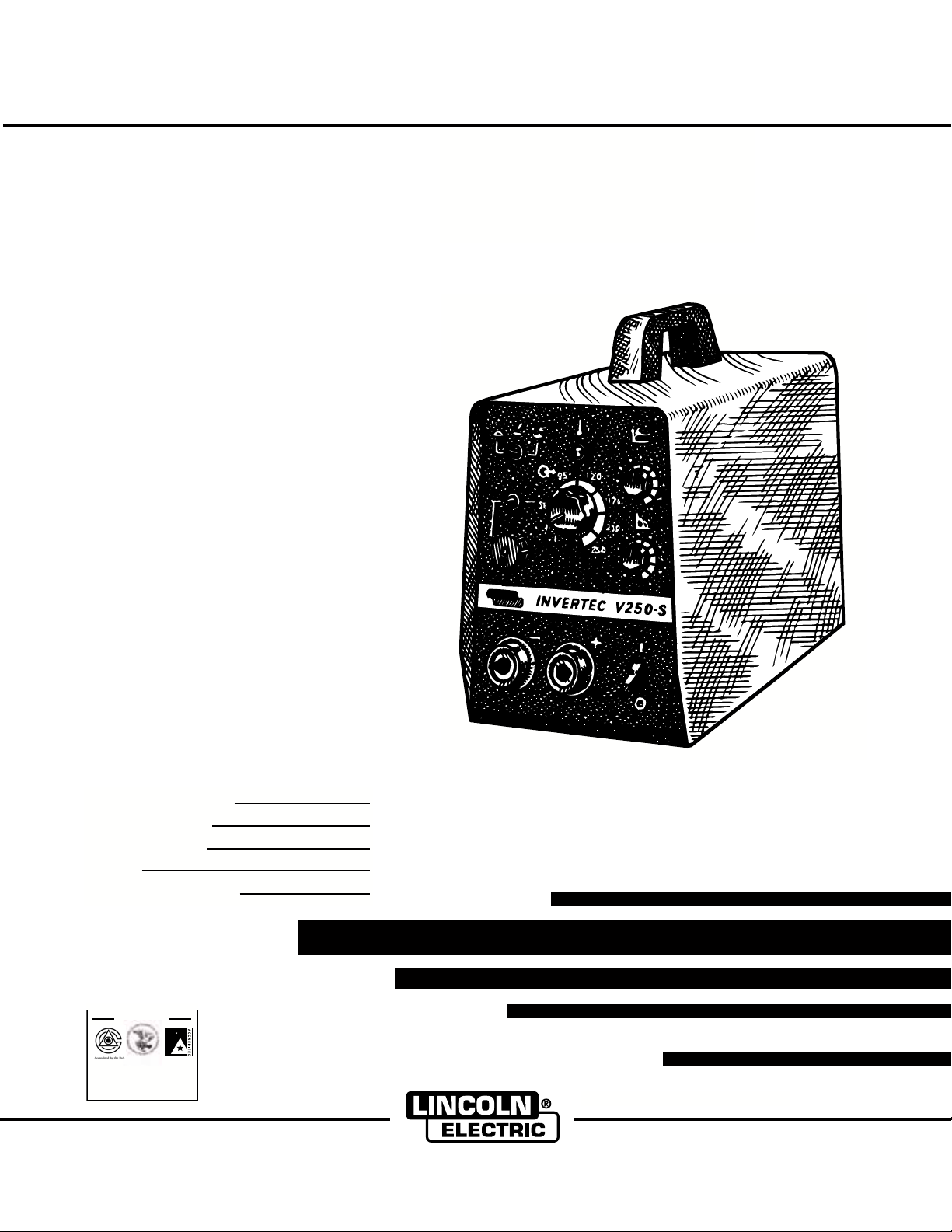
INVERTEC V250-S
For use with machines having Code Numbers:
Safety Depends on You
Lincoln arc welding and cutting
equipment is designed and built
with safety in mind. However, your
overall safety can be increased by
proper installation ... and thoughtful operation on your part. DO
NOT INSTALL, OPERATE OR
REPAIR THIS EQUIPMENT
WITHOUT READING THIS
MANUAL AND THE SAFETY
PRECAUTIONS CONTAINED
THROUGHOUT. And, most
importantly, think before you act
and be careful.
™
10102, 10103, 10187, 10188, 10304,
February, 2001
Date of Purchase:
Serial Number:
Code Number:
Model:
Where Purchased:
Designed and Manufactured Under a
Quality Program Certified by
ABS Quality Evaluations, Inc.
to ISO 9001 Requirements.
CERTIFICATE NUMBER: 30273
OPERATOR’S MANUAL
ISO 9001
ANSI RAB
QMS
Copyright © 2001 Lincoln Global Inc.
• World's Leader in Welding and Cutting Products •
• Sales and Service through Subsidiaries and Distributors Worldwide •
Cleveland, Ohio 44117-1199 U.S.A. TEL: 216.481.8100 FAX: 216.486.1751 WEB SITE: www.lincolnelectric.com
Page 2
i
SAFETY
i
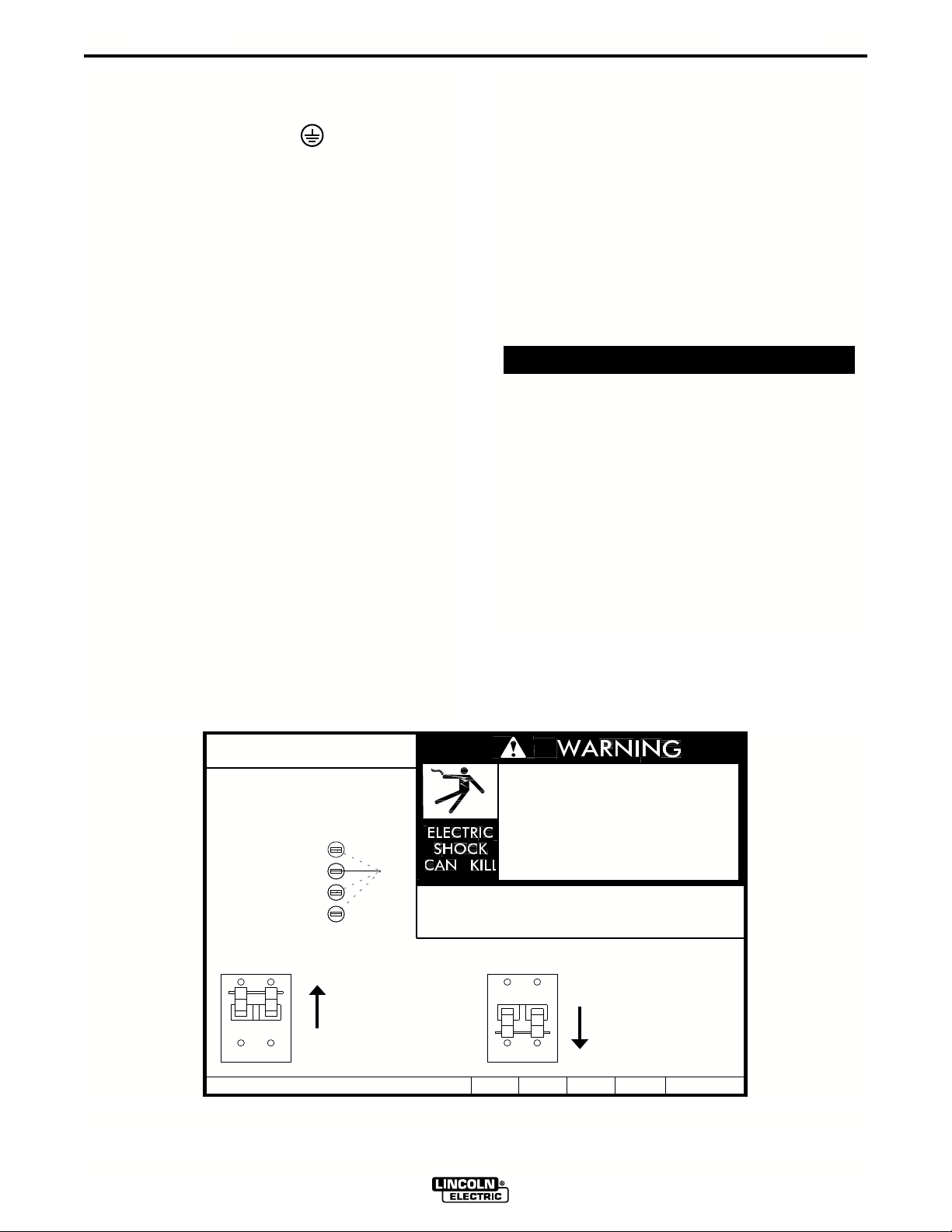
WARNING
CALIFORNIA PROPOSITION 65 WARNINGS
Diesel engine exhaust and some of its constituents
are known to the State of California to cause cancer, birth defects, and other reproductive harm.
The Above For Diesel Engines
ARC WELDING CAN BE HAZARDOUS. PROTECT YOURSELF AND OTHERS FROM POSSIBLE SERIOUS INJURY OR DEATH.
KEEP CHILDREN AWAY. PACEMAKER WEARERS SHOULD CONSULT WITH THEIR DOCTOR BEFORE OPERATING.
Read and understand the following safety highlights. For additional safety information, it is strongly recommended that you
purchase a copy of “Safety in Welding & Cutting - ANSI Standard Z49.1” from the American Welding Society, P.O. Box
351040, Miami, Florida 33135 or CSA Standard W117.2-1974. A Free copy of “Arc Welding Safety” booklet E205 is available
from the Lincoln Electric Company, 22801 St. Clair Avenue, Cleveland, Ohio 44117-1199.
BE SURE THAT ALL INSTALLATION, OPERATION, MAINTENANCE AND REPAIR PROCEDURES ARE
PERFORMED ONLY BY QUALIFIED INDIVIDUALS.
The engine exhaust from this product contains
chemicals known to the State of California to cause
cancer, birth defects, or other reproductive harm.
The Above For Gasoline Engines
FOR ENGINE
powered equipment.
1.a. Turn the engine off before troubleshooting and maintenance
work unless the maintenance work requires it to be running.
____________________________________________________
1.b. Operate engines in open, well-ventilated
areas or vent the engine exhaust fumes
outdoors.
____________________________________________________
1.c. Do not add the fuel near an open flame
welding arc or when the engine is running.
Stop the engine and allow it to cool before
refueling to prevent spilled fuel from vaporizing on contact with hot engine parts and
igniting. Do not spill fuel when filling tank. If
fuel is spilled, wipe it up and do not start
engine until fumes have been eliminated.
____________________________________________________
1.d. Keep all equipment safety guards, covers and devices in
position and in good repair.Keep hands, hair, clothing and
tools away from V-belts, gears, fans and all other moving
parts when starting, operating or repairing equipment.
____________________________________________________
1.e. In some cases it may be necessary to remove safety
guards to perform required maintenance. Remove
guards only when necessary and replace them when the
maintenance requiring their removal is complete.
Always use the greatest care when working near moving
parts.
___________________________________________________
1.f. Do not put your hands near the engine fan.
Do not attempt to override the governor or
idler by pushing on the throttle control rods
while the engine is running.
1.h. To avoid scalding, do not remove the
radiator pressure cap when the engine is
hot.
ELECTRIC AND
MAGNETIC FIELDS
may be dangerous
2.a. Electric current flowing through any conductor causes
localized Electric and Magnetic Fields (EMF). Welding
current creates EMF fields around welding cables and
welding machines
2.b. EMF fields may interfere with some pacemakers, and
welders having a pacemaker should consult their physician
before welding.
2.c. Exposure to EMF fields in welding may have other health
effects which are now not known.
2.d. All welders should use the following procedures in order to
minimize exposure to EMF fields from the welding circuit:
2.d.1.
Route the electrode and work cables together - Secure
them with tape when possible.
2.d.2. Never coil the electrode lead around your body.
2.d.3. Do not place your body between the electrode and
work cables. If the electrode cable is on your right
side, the work cable should also be on your right side.
___________________________________________________
1.g. To prevent accidentally starting gasoline engines while
turning the engine or welding generator during maintenance
work, disconnect the spark plug wires, distributor cap or
magneto wire as appropriate.
2.d.4. Connect the work cable to the workpiece as close as
possible to the area being welded.
2.d.5. Do not work next to welding power source.
Mar ‘95
Page 3

ii
SAFETY
ii
ELECTRIC SHOCK can
kill.
3.a. The electrode and work (or ground) circuits
are electrically “hot” when the welder is on.
Do not touch these “hot” parts with your bare
skin or wet clothing. Wear dry, hole-free
gloves to insulate hands.
3.b. Insulate yourself from work and ground using dry insulation.
Make certain the insulation is large enough to cover your full
area of physical contact with work and ground.
In addition to the normal safety precautions, if welding
must be performed under electrically hazardous
conditions (in damp locations or while wearing wet
clothing; on metal structures such as floors, gratings or
scaffolds; when in cramped positions such as sitting,
kneeling or lying, if there is a high risk of unavoidable or
accidental contact with the workpiece or ground) use
the following equipment:
• Semiautomatic DC Constant Voltage (Wire) Welder.
• DC Manual (Stick) Welder.
• AC Welder with Reduced Voltage Control.
3.c. In semiautomatic or automatic wire welding, the electrode,
electrode reel, welding head, nozzle or semiautomatic
welding gun are also electrically “hot”.
3.d. Always be sure the work cable makes a good electrical
connection with the metal being welded. The connection
should be as close as possible to the area being welded.
3.e. Ground the work or metal to be welded to a good electrical
(earth) ground.
ARC RAYS can burn.
4.a. Use a shield with the proper filter and cover
plates to protect your eyes from sparks and
the rays of the arc when welding or observing
open arc welding. Headshield and filter lens
should conform to ANSI Z87. I standards.
4.b. Use suitable clothing made from durable flame-resistant
material to protect your skin and that of your helpers from
the arc rays.
4.c. Protect other nearby personnel with suitable, non-flammable
screening and/or warn them not to watch the arc nor expose
themselves to the arc rays or to hot spatter or metal.
FUMES AND GASES
can be dangerous.
5.a. Welding may produce fumes and gases
hazardous to health. Avoid breathing these
fumes and gases.When welding, keep
your head out of the fume. Use enough
ventilation and/or exhaust at the arc to keep
fumes and gases away from the breathing zone. When
welding with electrodes which require special
ventilation such as stainless or hard facing (see
instructions on container or MSDS) or on lead or
cadmium plated steel and other metals or coatings
which produce highly toxic fumes, keep exposure as
low as possible and below Threshold Limit Values (TLV)
using local exhaust or mechanical ventilation. In
confined spaces or in some circumstances, outdoors, a
respirator may be required. Additional precautions are
also required when welding on galvanized steel.
3.f.
Maintain the electrode holder, work clamp, welding cable and
welding machine in good, safe operating condition. Replace
damaged insulation.
3.g. Never dip the electrode in water for cooling.
3.h. Never simultaneously touch electrically “hot” parts of
electrode holders connected to two welders because voltage
between the two can be the total of the open circuit voltage
of both welders.
3.i. When working above floor level, use a safety belt to protect
yourself from a fall should you get a shock.
3.j. Also see Items 6.c. and 8.
5.b.
Do not weld in locations near chlorinated hydrocarbon
coming from degreasing, cleaning or spraying operations.
The heat and rays of the arc can react with solvent vapors
form phosgene, a highly toxic gas, and other irritating
products.
5.c. Shielding gases used for arc welding can displace air and
cause injury or death. Always use enough ventilation,
especially in confined areas, to insure breathing air is safe.
5.d. Read and understand the manufacturer’s instructions for this
equipment and the consumables to be used, including the
material safety data sheet (MSDS) and follow your
employer’s safety practices. MSDS forms are available from
your welding distributor or from the manufacturer.
5.e. Also see item 1.b.
Mar ‘95
vapors
to
Page 4

iii
SAFETY
iii
WELDING SPARKS can
cause fire or explosion.
6.a.
Remove fire hazards from the welding area.
If this is not possible, cover them to prevent
the welding sparks from starting a fire.
materials from welding can easily go through small cracks
and openings to adjacent areas. Avoid welding near
hydraulic lines. Have a fire extinguisher readily available.
6.b. Where compressed gases are to be used at the job site,
special precautions should be used to prevent hazardous
situations. Refer to “Safety in Welding and Cutting” (ANSI
Standard Z49.1) and the operating information for the
equipment being used.
6.c. When not welding, make certain no part of the electrode
circuit is touching the work or ground. Accidental contact
can cause overheating and create a fire hazard.
6.d. Do not heat, cut or weld tanks, drums or containers until the
proper steps have been taken to insure that such procedures
will not cause flammable or toxic vapors from substances
inside. They can cause an explosion even
been “cleaned”. For information, purchase “Recommended
Safe Practices for the
Containers and Piping That Have Held Hazardous
Substances”, AWS F4.1 from the American Welding Society
(see address above).
6.e. Vent hollow castings or containers before heating, cutting or
welding. They may explode.
Sparks and spatter are thrown from the welding arc. Wear oil
6.f.
free protective garments such as leather gloves, heavy shirt,
cuffless trousers, high shoes and a cap over your hair. Wear
ear plugs when welding out of position or in confined places.
Always wear safety glasses with side shields when in a
welding area.
6.g. Connect the work cable to the work as close to the welding
area as practical. Work cables connected to the building
framework or other locations away from the welding area
increase the possibility of the welding current passing
through lifting chains, crane cables or other alternate circuits. This can create fire hazards or overheat lifting chains
or cables until they fail.
6.h. Also see item 1.c.
Remember that welding sparks and hot
though
they have
Preparation
for Welding and Cutting of
CYLINDER may explode
if damaged.
7.a. Use only compressed gas cylinders
containing the correct shielding gas for the
process used and properly operating
regulators designed for the gas and
pressure used. All hoses, fittings, etc. should be suitable for
the application and maintained in good condition.
7.b. Always keep cylinders in an upright position securely
chained to an undercarriage or fixed support.
7.c. Cylinders should be located:
• Away from areas where they may be struck or subjected to
physical damage.
• A safe distance from arc welding or cutting operations and
any other source of heat, sparks, or flame.
7.d. Never allow the electrode, electrode holder or any other
electrically “hot” parts to touch a cylinder.
7.e. Keep your head and face away from the cylinder valve outlet
when opening the cylinder valve.
7.f. Valve protection caps should always be in place and hand
tight except when the cylinder is in use or connected for
use.
7.g. Read and follow the instructions on compressed gas
cylinders, associated equipment, and CGA publication P-l,
“Precautions for Safe Handling of Compressed Gases in
Cylinders,” available from the Compressed Gas Association
1235 Jefferson Davis Highway, Arlington, VA 22202.
FOR ELECTRICALLY
powered equipment.
8.a. Turn off input power using the disconnect
switch at the fuse box before working on
the equipment.
8.b. Install equipment in accordance with the U.S. National
Electrical Code, all local codes and the manufacturer’s
recommendations.
8.c. Ground the equipment in accordance with the U.S. National
Electrical Code and the manufacturer’s recommendations.
Mar ‘95
Page 5

iv
SAFETY
iv
PRÉCAUTIONS DE SÛRETÉ
Pour votre propre protection lire et observer toutes les instructions et les précautions de sûreté specifiques qui parraissent
dans ce manuel aussi bien que les précautions de sûreté
générales suivantes:
Sûreté Pour Soudage A L’Arc
1. Protegez-vous contre la secousse électrique:
a. Les circuits à l’électrode et à la piéce sont sous tension
quand la machine à souder est en marche. Eviter toujours
tout contact entre les parties sous tension et la peau nue
ou les vétements mouillés. Porter des gants secs et sans
trous pour isoler les mains.
b. Faire trés attention de bien s’isoler de la masse quand on
soude dans des endroits humides, ou sur un plancher
metallique ou des grilles metalliques, principalement dans
les positions assis ou couché pour lesquelles une
grande partie du corps peut être en contact avec la
masse.
c. Maintenir le porte-électrode, la pince de masse, le câble
de soudage et la machine à souder en bon et sûr état
defonctionnement.
d.Ne jamais plonger le porte-électrode dans l’eau pour le
refroidir.
e. Ne jamais toucher simultanément les parties sous tension
des porte-électrodes connectés à deux machines à souder parce que la tension entre les deux pinces peut être le
total de la tension à vide des deux machines.
f. Si on utilise la machine à souder comme une source de
courant pour soudage semi-automatique, ces precautions
pour le porte-électrode s’applicuent aussi au pistolet de
soudage.
5. Toujours porter des lunettes de sécurité dans la zone de
soudage. Utiliser des lunettes avec écrans lateraux dans les
zones où l’on pique le laitier.
6. Eloigner les matériaux inflammables ou les recouvrir afin de
prévenir tout risque d’incendie dû aux étincelles.
7. Quand on ne soude pas, poser la pince à une endroit isolé de
la masse. Un court-circuit accidental peut provoquer un
échauffement et un risque d’incendie.
8. S’assurer que la masse est connectée le plus prés possible
de la zone de travail qu’il est pratique de le faire. Si on place
la masse sur la charpente de la construction ou d’autres
endroits éloignés de la zone de travail, on augmente le risque
de voir passer le courant de soudage par les chaines de levage, câbles de grue, ou autres circuits. Cela peut provoquer
des risques d’incendie ou d’echauffement des chaines et des
câbles jusqu’à ce qu’ils se rompent.
9. Assurer une ventilation suffisante dans la zone de soudage.
Ceci est particuliérement important pour le soudage de tôles
galvanisées plombées, ou cadmiées ou tout autre métal qui
produit des fumeés toxiques.
10. Ne pas souder en présence de vapeurs de chlore provenant
d’opérations de dégraissage, nettoyage ou pistolage. La
chaleur ou les rayons de l’arc peuvent réagir avec les
vapeurs du solvant pour produire du phosgéne (gas fortement toxique) ou autres produits irritants.
11. Pour obtenir de plus amples renseignements sur la sûreté,
voir le code “Code for safety in welding and cutting” CSA
Standard W 117.2-1974.
2. Dans le cas de travail au dessus du niveau du sol, se protéger contre les chutes dans le cas ou on recoit un choc. Ne
jamais enrouler le câble-électrode autour de n’importe quelle
partie du corps.
3. Un coup d’arc peut être plus sévère qu’un coup de soliel,
donc:
a. Utiliser un bon masque avec un verre filtrant approprié
ainsi qu’un verre blanc afin de se protéger les yeux du
rayonnement de l’arc et des projections quand on soude
ou quand on regarde l’arc.
b. Porter des vêtements convenables afin de protéger la
peau de soudeur et des aides contre le rayonnement de
l‘arc.
c. Protéger l’autre personnel travaillant à proximité au
soudage à l’aide d’écrans appropriés et non-inflammables.
4. Des gouttes de laitier en fusion sont émises de l’arc de
soudage. Se protéger avec des vêtements de protection
libres de l’huile, tels que les gants en cuir, chemise épaisse,
pantalons sans revers, et chaussures montantes.
PRÉCAUTIONS DE SÛRETÉ POUR
LES MACHINES À SOUDER À
TRANSFORMATEUR ET À
REDRESSEUR
1. Relier à la terre le chassis du poste conformement au code
de l’électricité et aux recommendations du fabricant. Le dispositif de montage ou la piece à souder doit être branché à
une bonne mise à la terre.
2. Autant que possible, I’installation et l’entretien du poste
seront effectués par un électricien qualifié.
3. Avant de faires des travaux à l’interieur de poste, la
debrancher à l’interrupteur à la boite de fusibles.
4. Garder tous les couvercles et dispositifs de sûreté à leur
place.
Mar. ‘93
Page 6

Thank You
vv
for selecting a QUALITY product by Lincoln Electric. We want you
to take pride in operating this Lincoln Electric Company product
••• as much pride as we have in bringing this product to you!
Please Examine Carton
When this equipment is shipped, title passes to the purchaser upon receipt by the carrier. Consequently, Claims
for material damaged in shipment must be made by the purchaser against the transportation company at the
time the shipment is received.
Please record your equipment identification information below for future reference. This information can be
found on your machine nameplate.
Model Name & Number _____________________________________
Code & Serial Number _____________________________________
Date of Purchase _____________________________________
Whenever you request replacement parts for or information on this equipment always supply the information
you have recorded above.
Read this Operators Manual completely before attempting to use this equipment. Save this manual and keep it
handy for quick reference. Pay particular attention to the safety instructions we have provided for your protection.
The level of seriousness to be applied to each is explained below:
and Equipment For Damage Immediately
WARNING
This statement appears where the information must be followed exactly to avoid serious personal injury or
loss of life.
CAUTION
This statement appears where the information must be followed to avoid minor personal injury or damage to
this equipment.
INVERTEC V250-S
Page 7

TABLE OF CONTENTS
PAGE
INSTALLATION .......................................................................................................................SECTION A
TECHNICAL SPECIFICATIONS ........................................................................................A-1 & A-2
SAFETY PRECAUTIONS ............................................................................................................A-3
SELECT SUITABLE LOCATION..................................................................................................A-3
INPUT CONNECTIONS ...............................................................................................................A-3
INPUT VOLTAGE RECONNECT PROCEDURE.........................................................................A-4
OUTPUT CONNECTIONS ...........................................................................................................A-5
OPERATION .......................................................................................................................SECTION B
SAFETY INSTRUCTIONS ...........................................................................................................B-1
GENERAL DESCRIPTION...........................................................................................................B-1
CONTROLS AND SETTINGS......................................................................................................B-2
CONSTANT CURRENT PROCESSES........................................................................................B-3
PARALLEL OPERATION .............................................................................................................B-4
OVERLOAD PROTECTION.........................................................................................................B-4
THERMAL PROTECTION............................................................................................................B-4
ACCESSORIES .......................................................................................................................SECTION C
OPTIONS / ACCESSORIES ........................................................................................................C-1
CABLE PLUGS......................................................................................................................C-1
REMOTE CONTROLS ..........................................................................................................C-1
vi
MAINTENANCE .......................................................................................................................SECTION D
INPUT FILTER CAPACITOR DISCHARGE PROCEDURE.........................................................D-1
ROUTINE MAINTENANCE..........................................................................................................D-2
FILTER CAPACITOR CONDITIONING ......................................................................................D-2
LOCATION OF MAINTENANCE COMPONENTS.......................................................................D-3
TROUBLESHOOTING................................................................................................................SECTION E
PC BOARD TROUBLESHOOTING PROCEDURES.............................................................E-1
TROUBLESHOOTING GUIDE ..............................................................................................E-2
DIAGRAMS ........................................................................................................................SECTION F
PARTS MANUAL ...................................................................................................................P-244 SERIES
INVERTEC V250-S
Page 8
A-1
INSTALLATION
Technical Specifications - Invertec V250-S - K1436-1, K1437-1 & K1437-3
INPUT
THREE PHASE SINGLE PHASE
Standard Input Current
Voltage
at Rated Output Model
208/230/460 60Hz 34/32/16 60Hz
200/220/400/440 50/60Hz 35/33/18/17 50/60 Hz
380-415 50Hz 20/18 50Hz
RATED OUTPUT
THREE PHASE SINGLE PHASE
Standard Input Current
Voltage
at Rated Output Model
208/230/460 60Hz 59/57/29 60Hz
200/220/400/440 50/60 Hz 58/58/30/30 50/60 Hz
A-1
Volts at
Duty Cycle
(1)
Amps Rated Amps Model
35% Duty Cycle 250 30 60Hz
60% Duty Cycle 200 28-32 60Hz
100% Duty Cycle 165 26.5 60Hz
35% Duty Cycle 250 28†-30 50/60Hz
60% Duty Cycle 200 29-32 50/60Hz
100% Duty Cycle 165 26.5 50/60Hz
35% Duty Cycle 250 30 50Hz
60% Duty Cycle 200 28 50Hz
100% Duty Cycle 165 26 50Hz
THREE PHASE SINGLE PHASE
Welding Constant Open
Current Range
Circuit Voltage
1-250 Amps 65-80 VDC
RECOMMENDED INPUT WIRE AND FUSE SIZES
THREE PHASE SINGLE PHASE
Type 75°C
Type 75°C Copper
Fuse Input Copper Ground
(Superlag) Ampere Wire in Wire in
Input or Rating Conduit Conduit
Voltage Breaker on AWG (IEC) AWG (IEC)
Frequency
(2)
Size Nameplate Sizes Sizes
Volts at
Duty Cycle
(1)
Amps Rated Amps Model
35% Duty Cycle 250 27†-30 60Hz
60% Duty Cycle 200 28-32 60Hz
100% Duty Cycle 165 26.5 60Hz
35% Duty Cycle 250 26†-30 50/60Hz
60% Duty Cycle 200 28-32 50/60Hz
100% Duty Cycle 165 26.5 50/60Hz
OUTPUT
Welding Constant Open
Current Range
1-250 Amps 65-80 VDC
Fuse Input Copper Ground
(Superlag) Ampere Wire in Wire in
Input or Rating Conduit Conduit
Voltage Breaker on AWG (IEC) AWG (IEC)
Frequency
(2)
Size Nameplate Sizes Sizes
Circuit Voltage
Type 75°C Copper
Type 75°C
208/60 50 34 10 (6mm
230/60 50 32 10(6mm2) 10 (6mm2)
460/60 30 16 10 (6mm2) 10 (6mm2)
200/50/60 50 35 10 (6mm
220/50/60 50 33 10 (6mm2) 10 (6mm2)
400/50/60 30 18 12 (4mm2) 12 (4mm2)
440/50/60 30 17 12 (4mm2) 12 (4mm2)
2
) 10 (6mm2)
2
) 10 (6mm2)
(3)
208/60
(3)
230/60
460/60 40 29 10 (6mm2) 10 (6mm2)
200/50/60 80 58 8 (8.4mm
220/50/60 80 58 8 (8.4mm2) 10 (6mm2)
400/50/60 40 30 10 (6mm2) 10 (6mm2)
440/50/60 40 30 10 (6mm2) 10 (6mm2)
80 59 8 (8.4mm2) 10 (6mm2)
80 57 8 (8.4mm2) 10 (6mm2)
PHYSICAL DIMENSIONS
Height Width Depth Weight
15.0 in. 9.1 in. 19.7 in. 36 lbs.
381 mm 231 mm 500 mm 17 Kg
(1) Based on a 10 min. period. (2) Input voltage must be within ±10% of rated value.
(†)
200 & 208VAC input may not meet NEMA/IEC specifications at 250 Amps.
INVERTEC V250-S
2
) 10 (6mm2)
Page 9
A-2
INSTALLATION
Technical Specifications - Invertec V250-S - K1437-2
INPUT
THREE PHASE SINGLE PHASE
Standard Input Current
Voltage
at Rated Output Model
220/440 35% Duty Cycle 34/17 50/60 Hz
400 60% Duty Cycle 16 50/60 Hz
220/400/440 100% Duty Cycle
19/11/9 50/60 Hz
RATED OUTPUT
THREE PHASE SINGLE PHASE
Standard Input Current
Voltage
220/440 35% Duty Cycle 57/29 50/60 Hz
400 60% Duty Cycle 27 50/60 Hz
220/400/440 100% Duty Cycle
A-2
at Rated Output Model
34/21/17 50/60 Hz
Duty Cycle
(1)
35% Duty Cycle
Amps Rated Amps Model
(3)
250 30V 50/60Hz
60% Duty Cycle 200 28V 50/60Hz
100% Duty Cycle 155 26.2V 50/60Hz
THREE PHASE SINGLE PHASE
Volts at
Welding Constant Open
Current Range
Circuit Voltage
RECOMMENDED INPUT WIRE AND FUSE SIZES
THREE PHASE SINGLE PHASE
Type 75°C
Type 75°C Copper
Fuse Input Copper Ground
(Superlag) Ampere Wire in Wire in
Input or Rating Conduit Conduit
Voltage Breaker on AWG (IEC) AWG (IEC)
Frequency
(2)
Size Nameplate Sizes Sizes
Duty Cycle
(1)
35% Duty Cycle
Amps Rated Amps Model
(3)
230 29V 50/60Hz
60% Duty Cycle 190 27.6V 50/60Hz
100% Duty Cycle 155 26.2V 50/60Hz
OUTPUT
Welding Constant Open
Volts at
Current Range
Fuse Input Copper Ground
(Superlag) Ampere Wire in Wire in
Input or Rating Conduit Conduit
Voltage Breaker on AWG (IEC) AWG (IEC)
Frequency
(2)
Size Nameplate Sizes Sizes
Circuit Voltage
Type 75°C Copper
Type 75°C
208/60 50 34 10 (6mm
230/60 50 32 10(6mm2) 10 (6mm2)
460/60 30 16 10 (6mm2) 10 (6mm2)
200/50/60 50 35 10 (6mm2) 10 (6mm2)
220/50/60 50 33 10 (6mm2) 10 (6mm2)
400/50/60 20 18 12 (4mm2) 12 (4mm2)
440/50/60 20 17 12 (4mm2) 12 (4mm2)
2
) 10 (6mm2)
PHYSICAL DIMENSIONS
Height Width Depth Weight
15.0 in. 9.1 in. 19.7 in. 41 lbs.
381 mm 231 mm 500 mm 19 Kg
(1) Based on a 10 min. period.
(2) Input voltage must be within ±10% of rated value.
(3) Excluding 400V-VAC Input
INVERTEC V250-S
(3)
208/60
(3)
230/60
460/60 40 29 10 (6mm2) 10 (6mm2)
200/50/60 80 58 8 (8.4mm2) 10 (6mm2)
220/50/60 80 58 8 (8.4mm2) 10 (6mm2)
400/50/60 40 30 10 (6mm2) 10 (6mm2)
440/50/60 40 30 10 (6mm2) 10 (6mm2)
80 59 8 (8.4mm2) 10 (6mm2)
80 57 8 (8.4mm2) 10 (6mm2)
Page 10

A-3
INSTALLATION
A-3
Read this entire installation section before you
start installation.
SAFETY PRECAUTIONS
WARNING
ELECTRIC SHOCK can kill.
• Have an electrician install and service this equipment.
• Turn the input power off at the fuse
box before working on equipment.
• Do not touch electrically hot parts.
• Be sure to discharge capacitors with
the procedure outlined in the
Maintenance Section of this manual
before working in that area of the
equipment.
---------------------------------------------------------------------
SELECT SUITABLE LOCATION
The Invertec V250-S will operate in harsh environments. Even so, it is important that simple preventative measures are followed in order to assure long life
and reliable operation.
HIGH FREQUENCY PRECAUTIONS
If possible locate the V250-S away from radio controlled machinery. The normal operation of the
V250-S may adversely affect the operation of RF controlled equipment, which may result in bodily injury or
damage to the equipment.
INPUT CONNECTIONS
The Invertec V250-S should be connected only by a
qualified electrician. Installation should be made in
accordance with all local and national electric codes
and the information detailed below.
GROUND CONNECTION
Ground per National Electrical Code for 60Hz
machines connect the green lead to earth ground.
For 50/60Hz machines connect the ground terminal
marked located in the machine on the lower right
side the base of the welder to earth ground.
INPUT SUPPLY CONNECTIONS
Be sure the voltage phase and frequency of the input
power is as specified on the rating plate, located on
the rear of the machine.
• The machine must be located where there is free circulation of clean air such that air movement in the
back and out the front will not be restricted.
• Dirt and dust that can be drawn into the machine
should be kept to a minimum. Failure to observe
these precautions can result in excessive operating
temperatures and nuisance shutdown.
• Keep machine dry. Shelter from rain and snow. Do
not place on wet ground or in puddles.
STACKING
V250-S’s cannot be stacked.
TILTING
Place the machine directly on a secure, level surface
or on a recommended undercarriage. The machine
may topple over if this procedure is not followed.
Supply line entry provision is in the case rear panel.
POWER INPUT CONNECTION FOR 60HZ
MACHINES
A 10 ft. power cord is provided and wired into the
machine. Follow the power cord connection instructions. Incorrect connection may result in equipment
damage.
Single Phase Input: Connect green lead to ground
per U.S. National Electrical Code. Connect black and
white leads to power. Wrap red lead with tape to provide 600V insulation.
Three Phase Input: Connect green lead to ground
per U.S. National Electrical Code. Connect black, red
and white leads to power.
INVERTEC V250-S
Page 11
A-4
INSTALLATION
A-4
POWER INPUT CONNECTION FOR 50/60 HZ
MACHINES
1. Connect terminal marked to earth ground
per National Electric Code.
2. Connect the supply lines to the line switch. Torque
to 3.0 Nm.
3. Install in accordance with all local and national
electric codes.
The Invertec V250-S machine is supplied with one
cord connector. The cord connector provides a strain
relief for the input power cord as it passes it through
the rear access hole. On K1436-1, K1437-1 and
K1437-3, the cord connector is designed for a cord
diameter of 7.9 to 27.2mm (.310 to 1.070 in). On
K1437-2 the cord connector is designed for a cord
diameter of 11.4 to 20.0mm (.450 to .790 in).
Strip away outer jacket of cord, trim fillers and insert
conductors through cord connector. The jacketed portion of the cord must go through the cord connector.
Tighten both connector screws.
INPUT FUSE AND SUPPLY WIRE
Refer to the Technical Specifications page at the
beginning of this chapter for the proper fuse sizes and
supply cable sizes.
INPUT VOLTAGE RECONNECT
PROCEDURE
When received directly from the factory, units are connected for the highest input voltage, 440 VAC for
50/60 Hz machines and 460 VAC for 60 Hz machines.
If 440 or 460 VAC is the desired input, then the
machine may be connected to the power system without any setup required inside the reconnect door.
However, verify the connection with the following procedure. For other voltages refer to the instructions
located on the Reconnect Panel Access Door or follow the instructions below.
CAUTION
Failure to follow these instructions can cause immediate failure of components within the welder.
------------------------------------------------------------------------
1. Open the access door on the right side of the
machine.
2. For 200-230: Position the large switch to 200-230.
For 380-460: Position the large switch to 380-460.
3. Move the “A” lead to the appropriate terminal.
Refer to figure A.1 below.
• Fuse the input circuit with recommended super lag
fuses or delay type circuit breakers.
• Install the proper fuse in the fuse holder in the main
disconnect panel.
RECONNECT PROCEDURE
1. BE SURE POWER SWITCH IS OFF.
2. CONNECT LEAD 'A' TO DESIRED
INPUT VOLTAGE RANGE.
440-460V
380-415V
220-230V
200-208V
3. POSITION SWITCH TO DESIRED INPUT VOLTAGE RANGE.
VOLTAGE=380-460V
THE LINCOLN ELECTRIC CO. CLEVELAND, OHIO U.S.A.
Figure A.1 Input Voltage Reconnect Instructions
'A'
IF MACHINE CEASES TO OPERATE (NO METER, NO FAN)
AND THERE IS NO OTHER KNOWN FAILURE: CHECK FUSE;
REPLACE WITH SPECIFIED FUSE.
.
Disconnect input power before
inspecting or servicing machine.
.
Do not operate with wraparound
removed.
.
Do not touch electrically live parts.
.
Only qualified persons should install,
use or service this equipment.
VOLTAGE=200-230V
A
S21230
INVERTEC V250-S
Page 12
A-5
OUTPUT CONNECTIONS
INSTALLATION
QUICK DISCONNECT PLUGS
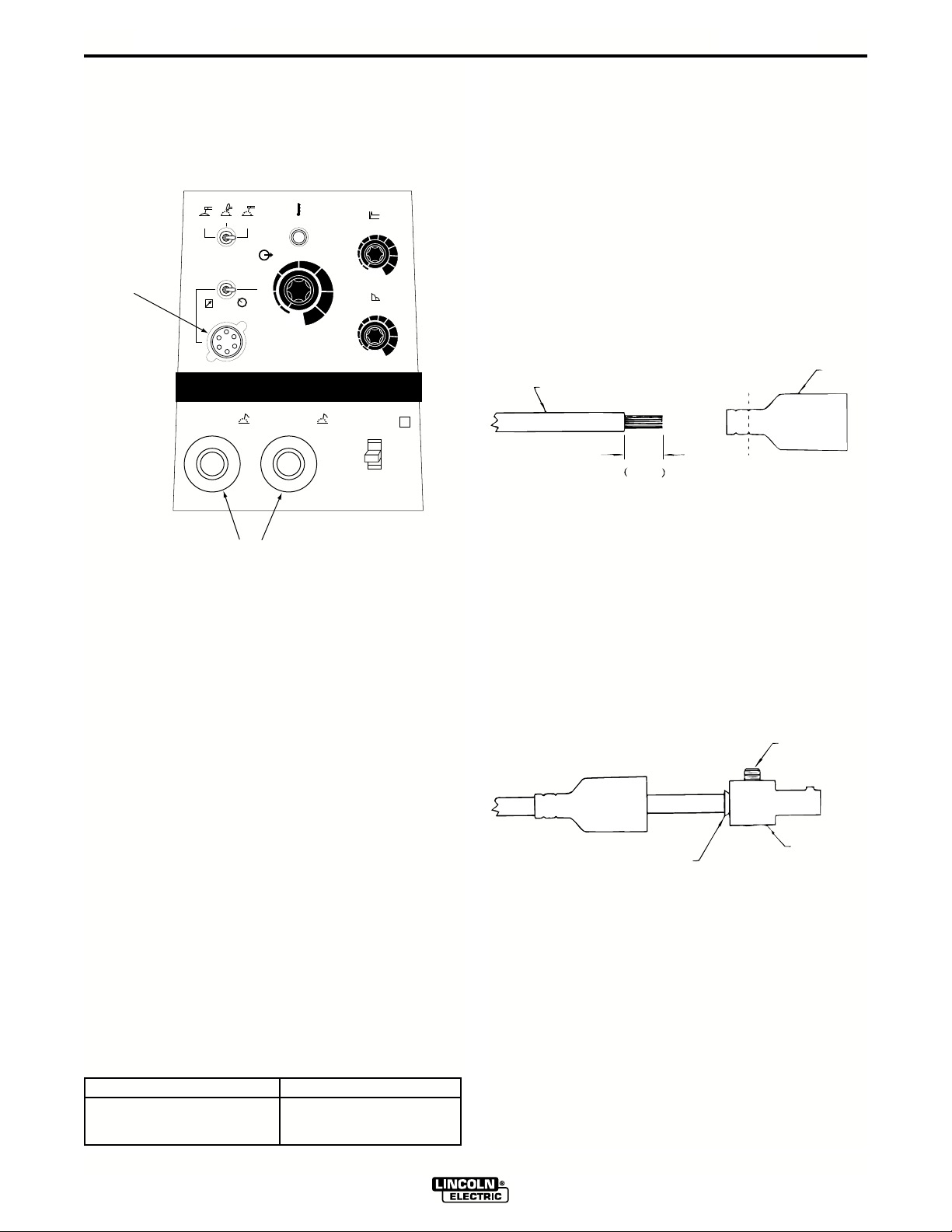
A-5
Refer to figure A.2 for the location of the 6 Pin Remote
Receptacle and the Output Terminals.
FIGURE A.2 OUTPUT CONNECTIONS
SMAW
SMAW
6 PIN
REMOTE
RECEPTACLE
GTAW
SOFT
CRISP
LOCAL
REMOTE
-
OUTPUT TERMINALS
THERMAL
A
120
85
OUTPUT
50
15
1
250
INVERTEC V250-S
+
HOT START
5
6
4
3
2
1
0
170
ARC FORCE
230
5
6
4
3
2
1
0
¤
I
O
7
8
9
10
7
8
9
10
S
A quick disconnect system is used for the welding
cable connections. The welding plug included with the
machine is designed to accept a welding cable size of
1/0 to 2/0.
1. Remove 1 in. (25mm) of welding cable insulation.
2. Slide rubber boot onto cable end. The boot end
may be trimmed to match the cable diameter.
Soap or other lubricant will help to slide the boot
over the cable.
BOOT
WELDING CABLE
25 mm
1 in.
TRIM
3. Slide the copper tube into the brass plug.
REMOTE CONTROL RECEPTACLE
Remote control (K857), Arc start switch (K814), Hand
amptrol (K963) and Foot amptrol (K870) connect
directly to 6 pin amphenol on the front of the unit.
Note: A minor modification is needed when K963
Hand Amptrol is used with the V250-S. The braided
grounding strap must be disconnected from connector
body on end of cable that attaches to machine.
Remove cable clamp screw securing grounding strap,
remove strap, and reinstall screw. Run grounding
strap along side of cable so that it does not contact
connector body, and secure in place with electrical
tape. This modification is necessary in order to avoid
coupling electrical noise from the case of the machine
onto the control leads, which would otherwise result in
poor starting and unstable welding performance.
OUTPUT CABLES
Select the output cable size based on Table A.1.
TABLE A.1
Cable Sizes for Combined Length of Electrode and
Work Cable ( Copper Cable Rated at 75°C).
4. Insert cable into copper tube.
5. Tighten set screw to collapse copper tube. Screw
must apply pressure against welding cable. The
top of the set screw will be well below the surface
of the brass plug after tightening.
SET SCREW
BRASS PLUG
COPPER TUBE
6. Slide rubber boot over brass plug. The rubber
boot must be positioned to completely cover all
electrical surfaces after the plug is locked into the
receptacle.
Length Cable Size
up to 150 ft.(46m) 1/0 (50mm
up to 250 ft.(72m) 2/0 (70mm2)
2
)
INVERTEC V250-S
Page 13

B-1
OPERATION
B-1
Read and understand this entire section before
operating your machine.
SAFETY INSTRUCTIONS
WARNING
ELECTRIC SHOCK can kill.
• Do not touch electrically live parts such
as output terminals or internal wiring.
• Insulate yourself from the work and
ground.
• Always wear dry insulating gloves.
____________________________________
FUMES AND GASES
can be dangerous.
• Keep your head out of fumes.
• Use ventilation or exhaust to
remove fumes from breathing
zone.
____________________________________
WELDING, CUTTING and
GOUGING SPARKS
can cause fire or explosion
GENERAL DESCRIPTION
The Invertec V250-S is a 250 amp arc welding power
source that utilizes single or three phase input power,
to produce constant current output. The welding
response of this Invertec has been optimized for stick
(SMAW) and TIG (GTAW).
OPERATIONAL FEATURES
The Invertec V250-S provides continuous total range
output current adjustment, selectable welding modes
and local or remote output control. Welding characteristics can be controlled via an arc force control.
Additionally, starting characteristics can be adjusted
via a “hot start” control.
WELDING CAPABILITY
The Invertec V250-S is rated at 250 amps, 35% duty
cycle (based on a 10 minute cycle). It is also rated at
165 amps, 100% duty cycle, and 200 amps, 60% duty
cycle.
LIMITATIONS
The V250-S is not recommended for pipe thawing.
The V250-S should not be powered from the auxiliary
power supply of an engine welder. Special protection
circuits may operate causing loss of output.
• Keep flammable material away.
• Do not weld, cut or gouge on
containers that have held com-
bustibles.
____________________________________
ARC RAYS
can burn.
• Wear eye, ear and body
protection.
____________________________________
Only qualified personnel should operate this equipment. Observe all safety information throughout this
manual.
INVERTEC V250-S
Page 14

B-2
OPERATION
B-2
CONTROLS AND SETTINGS
All operator controls and adjustments are located on the case front of the V250-S. Refer to Figure B.1 and corresponding explanations.
FIGURE B.1 — CASE FRONT CONTROLS.
4
SMAW
SOFT
GTAW
SMAW
CRISP
THERMAL
2
A
OUTPUT
3
REMOTE
LOCAL
50
15
120
85
1
INVERTEC V250-S
-
+
250
170
230
8
HOT START
5
6
4
0
ARC FORCE
5
4
0
I
7
8
9
10
6
7
8
9
10
5
6
S
3
2
1
3
2
1
®
1
O
7
1. Power Switch - Place the lever in the “ON” position to
energize the machine. When the power is on, the fan will
operate and the output will be energized in SMAW
modes. GTAW mode requires remote trigger to energize
the output.
2. Output Control - This controls the output current. Control
is provided over the entire output range of the power
source with 1 turn of the control knob. This control may
be adjusted while under load to change power source
output. When using remote control this function becomes
the limit setting.
3. Local/Remote Switch - Place in the “LOCAL” position to
allow output adjustment at the machine. Place in the
“REMOTE” position to allow output adjustment at remote
pot or amptrol. In Remote, the machine output control pot
is the limit setting for remote control.
4. Mode Switch
GTAW Optimized for touch start use. Triggering at
amphenol is required using an Arc Start Switch, Amptrol
or similar means. Short circuit current is limited to approximately 25 amps to aid in touch starting.
CC Soft Best for EXX18 thru EXX28 stick electrodes.
Output energized when machine is on.
CC Crisp Use this mode for stick welding with EXX10
thru EXX14 electrodes. Output energized when machine
is on.
5. Hot Start - Controls the amount of starting energy in
SMAW. The Hot Start setting will set the amount of extra
power given during the initial strike.
A Hot Start setting of 100% will give you an additional
striking current 100% above the welding set current*.
(Striking current in this example will be 200% of the set
current). For a Hot Start setting of 100%, the current will
decrease back to the set current in one second.
A Hot Start setting of 50% will give you an additional
striking current 50% above the welding set current*.
(Striking current in this example will be 150% of the set
current). For a Hot Start setting of 50%, the current will
decrease back to the set current in .5 second.
* The maximum striking current is 300 Amps.
INVERTEC V250-S
Page 15

B-3
OPERATION
B-3
6. Arc Force - This control functions in SMAW modes
to adjust the Arc Force. The arc is soft at the minimum settings and more forceful or driving at the
maximum settings. Higher spatter levels may be
present at the maximum settings.
RECOMMENDED ARC FORCE/INDUCTANCE
SETTINGS FOR SELECTED APPLICATIONS
FULL RANGE IS 1-10. 1 is VERY SOFT,
10 IS VERY CRISP
Nominal Recommended
Mode Process Setting Adjustment Range
CC SMAW 1 EXX18 thru 5 1 (gentle, may stick) to 9
(soft) EXX28 stick (forceful, more spatter)
CC SMAW 2 EXX10 thru 6 3 to 10
(crisp) EXX14 stick
Air Carbon Arc 1 None
Cutting
7. Output Terminals - These quick disconnect terminals provide connection points for the electrode and
work cables. Refer to Output Connections in the
Installation chapter for proper cable sizes. For
positive polarity welding connect the electrode
cable to the positive terminal and the work cable to
the negative terminal. To weld negative polarity
reverse the electrode and work cables.
CONSTANT CURRENT PROCESSES
MANUAL ARC WELDING (STICK)
The Invertec may be utilized as a manual DC arc
welder with the electrode cable, work cable, and electrode holder being the only equipment required.
AIR CARBON ARC CUTTING
Air carbon arc cutting may be performed with the
Invertec within its output rating using 5/32" (3.9mm)
and 3/16" (4.7mm) diameter carbon rods. Output
cables, an air carbon arc electrode cable assembly,
and a source of compressed air are required.
NOTE:
1. Best performance will be at settings of 200 amps
and below.
2. The electronic protection circuit in the V250S will
limit the current to approximately 290 amps.
TIG WELDING
The V250S is capable of touch start TIG welding. An
electrode cable, work cable, Arc Start Switch or
Amptrol, TIG torch, and gas supply with regulator are
required. Refer to
Touch starting is done as follows:
Accessories
section of this manual.
8. Thermal Shutdown Indicator - This light will illuminate if an internal thermostat has been activated.
Machine output will return after the internal
components have returned to a normal operating
temperature. See Thermal Protection later in this
chapter.
1. Place the shield cup edge on the work piece.
2. Rock the tungsten down to touch.
3. Trigger the output.
4. Gently rock back the tungsten from the workpiece.
Note: The short circuit current is limited to 25 amps to
aid in touch starting. Panel output control
becomes the current limit setting when in
remote control
INVERTEC V250-S
Page 16

B-4
OPERATION
PARALLEL OPERATION
The Invertec’s are operable in parallel. For best
results, the currents of each machine should be reasonably well shared. As an example, with two
machines set up in parallel for a 300 amp procedure,
each machine should be set to deliver approximately
150 amps, not 200 amps from one and 100 amps
from the other. This will minimize nuisance feedback
conditions. In general, more than two machines in parallel will not be effective due to the voltage requirements of procedures in that power range.
To set machine outputs, start with output control pots
and arc force pots in identical positions. Adjust outputs and arc forces to maintain current sharing while
establishing the proper output current.
OVERLOAD PROTECTION
The machine is electrically protected from producing
high output currents. Should the output current
exceed 290A, an electronic protection circuit will
reduce the current to less than 200A. The machine
will continue to produce this low current until the protection circuit is reset. Reset occurs when the output
load is removed.
B-4
THERMAL PROTECTION
Thermostats protect the machine from excessive
operating temperatures. Excessive temperatures may
be caused by a lack of cooling air or operating the
machine beyond the duty cycle and output rating. If
excessive operating temperature should occur, the
thermostats will prevent output voltage or current.
Thermostats are self-resetting once the machine cools
sufficiently. If the thermostat shutdown was caused by
excessive output or duty cycle and the fan is operating
normally, the Power Switch may be left on and the
reset should occur within a 15 minute period. If the fan
is not turning or the air intake louvers were obstructed,
then the power must be switched off for 15 minutes in
order to reset. The fan problem or air obstruction must
also be corrected.
INVERTEC V250-S
Page 17

C-1
ACCESSORIES
OPTIONS / ACCESSORIES
CABLE PLUGS
K852-70 - Cable Plug Kit for 1/0-2/0 cable. Attaches
to welding cable to provide quick disconnect from
machine.
K852-95 - Cable Plug Kit for 2.0-3/0 cable.
NOTE: Two K852-70 plugs are included with the
V250-S.
REMOTE CONTROLS
K857 - Remote Output Control for stick welding.
K963 - Hand Amptroltmfor TIG welding. When the
V250-S’s Output Control is in the “Remote” position,
the hand Amptrol energizes the output and controls
the output remotely. The Hand Amptrol connects
directly to the 6 pin Amphenol.
C-1
Note: When used with the V250-S, the grounding
strap on the connector end of K963 must be disconnected to avoid electrical noise problems. Details are
listed under REMOTE CONTROL RECEPTACLE in
INSTALLATION section in this manual.
K870 - Foot Amptrol
V250-S’s Output Control is in the “REMOTE” position,
the foot Amptrol energizes the output and controls the
output remotely. The Hand Amptrol connects directly
to the 6 pin Amphenol.
K814 - Arc Start Switch. Energizes the output for TIG
welding if remote output control of the amperage is
not desired. When using the Arc Start Switch set the
Output Control to the “LOCAL” position.
tm
for TIG welding. When the
INVERTEC V250-S
Page 18

D-1
MAINTENANCE
D-1
WARNING
ELECTRIC SHOCK can kill.
• Have an electrician install and service
this equipment.
• Turn the input power off at the fuse
box before working on equipment.
• Do not touch electrically hot parts.
• Prior to Performing preventative main-
tenance, perform the following capacitor discharge procedure to avoid electric shock.
---------------------------------------------------------------------
INPUT FILTER CAPACITOR
DISCHARGE PROCEDURE
1. Turn off input power or disconnect input power
lines.
2. Remove the 5/16" hex head screws from the side
and top of the machine and remove wrap-around
machine cover.
3. Be careful not to make contact with the capacitor
terminals that are located in the top and bottom of
the Power Board.
4. Obtain a high resistance and high wattage resistor
(25-1000 ohms and 25 watts minimum). This resistor is not supplied with machine. NEVER USE A
SHORTING STRAP FOR THIS PROCEDURE.
5. Locate the four capacitor terminals (large hex head
cap screws) shown in Figure D.1. One pair at the
top and one pair at the bottom of the Power Board.
6. Use electrically insulated gloves and insulated pliers. Hold body of the resistor and connect resistor
leads across the two capacitor terminals. Hold
resistor in place for 10 seconds. DO NOT TOUCH
CAPACITOR TERMINALS WITH YOUR BARE
HANDS.
7. Repeat discharge procedure for the capacitor on
other two terminals.
8. Check voltage across terminals of all capacitors
with a DC voltmeter. Polarity of capacitor terminals
is marked on PC board above terminals. Voltage
should be zero. If any voltage remains, repeat this
capacitor discharge procedure.
FIGURE D.1 — LOCATION OF INPUT FILTER CAPACITOR TERMINALS.
POWER
BOARD
RIGHT SIDE OF MACHINE
CAP ACIT OR TERMINALS
UPPER
LOWER
CAPACITOR
TERMINALS
POWER
RESISTOR
INSULATED
PLIERS
INSULATED
GLOVES
INVERTEC V250-S
Page 19

D-2
MAINTENANCE
D-2
ROUTINE MAINTENANCE
1. Perform the following preventive maintenance
procedures at least once every six months. It is
good practice to keep a preventive maintenance
record; a record tag attached to the machine
works best.
2. Remove the machine wrap-around cover and perform the input filter capacitor discharge procedure
(detail at the beginning of this chapter).
3. Keeping the machine clean will result in cooler
operation and higher reliability. Be sure to clean
the following areas with a low pressure air
stream. See figure D.2 for component locations.
• Power and control printed circuit boards
• Power switch
• Main transformer
• Input rectifier
• Heat sink fins
• Input Filter Capacitors
FILTER CAPACITOR CONDITIONING
A protection circuit is included to monitor the voltage
across filter capacitors C1 and C2. In the event that
the capacitor voltage is too high, the protection circuit
will prevent output. Nominal trip setting is at 230/460
VAC +15%. Reset occurs about 3% lower (230/460
VAC +12%).
On new installations, the protection circuit may also
prevent output providing all these circumstances are
met:
1. Machine is connected for 380-415 or 440-460
VAC input.
2. Machine did not have power applied for many
months.
3. Machine will not produce output when power is
first switched on.
If these circumstances apply, the proper action is to
switch the machine on and let it idle for up to 30 minutes. This is required to condition the filter capacitors
after an extended storage time. The protection circuit
will automatically reset once the capacitor conditioning
and resultant voltage levels are acceptable. It may be
necessary to turn the power switch off and back on
again after this period.
• Output Terminals
4. Examine capacitors for leakage or oozing. Replace
if needed.
5. Examine the sheet metal case for dents or break-
age. Repair the case as required. Keep the case
in good condition to ensure that high voltage
parts are protected and correct spacings are
maintained. All external sheet metal screws must
be in place to assure case strength and electrical
ground continuity.
6. Check electrical ground continuity. Using an ohmmeter, measure resistance between either output
terminal and an unpainted surface of the machine
case. (See Figure D.2 for locations.) Meter reading
should be 500,000 ohms or more. If meter reading
is less than 500,000 ohms, check for electrical
components that are not properly insulated from
the case. Correct insulation if needed.
7. Replace machine cover and screws.
INVERTEC V250-S
Page 20

D-3
MAINTENANCE
FIGURE D.2 — LOCATION OF MAINTENANCE COMPONENTS.
D-3
CONTROL PC BOARD
POWER SWITCH
OUTPUT TERMINALS
OUTPUT RECTIFIER
HEATSINK FINS
INPUT RECTIFIER
POWER PC BOARD
COOLING FANS
MAIN TRANSFORMER
AUXILIARY TRANSFORMER
INVERTEC V250-S
Page 21

E-1
TROUBLESHOOTING & REPAIR
PC BOARD TROUBLESHOOTING PROCEDURES
E-1
WARNING
ELECTRIC SHOCK can kill.
Have an electrician install
and service this equipment. Turn the input power
OFF at the fuse box before
working on equipment. Do
not touch electrically hot
parts.
_______________________________
CAUTION: Sometimes machine failures
appear to be due to PC board failures. These
problems can sometimes be traced to poor
electrical connections. To avoid problems
when troubleshooting and replacing PC
boards, please use the following procedure:
1. Determine to the best of your technical
ability that the PC board is the most likely
component causing the failure symptom.
2. Check for loose connections at the PC
board to assure that the PC board is properly connected.
3. If the problem persists, replace the suspect PC board using standard practices to
avoid static electrical damage and electrical shock. Read the warning inside the
static resistant bag and perform the following procedures:
- Remove the P.C. Board from the staticshielding bag and place it directly into the
equipment. Don’t set the P.C. Board on or
near paper, plastic or cloth which could have
a static charge. If the P.C. Board can’t be
installed immediately, put it back in the staticshielding bag.
- If the P.C. Board uses protective shorting
jumpers, don’t remove them until installation
is complete.
- If you return a P.C. Board to The Lincoln
Electric Company for credit, it must be in the
static-shielding bag. This will prevent further
damage and allow proper failure analysis.
4. Test the machine to determine if the failure symptom has been corrected by the
replacement PC board.
NOTE: It is desirable to have a spare (known
good) PC board available for PC board troubleshooting.
NOTE: Allow the machine to heat up so that
all electrical components can reach their operating temperature.
5. Remove the replacement PC board and
substitute it with the original PC board to
recreate the original problem.
P.C. Board can be damaged by static electricity.
- Remove your body’s static charge before opening
ATTENTION
Static-Sensitive
Devices
Handle only at
Static-Safe
Workstations
Reusable
Container
Do Not Destroy
equipment frame. Keep touching the frame to
prevent static build-up. Be sure not to touch
any electrically live parts at the same time.
- Tools which come in contact with the P.C.
Board must be either conductive, anti-static or
static-dissipative.
the static-shielding bag.
Wear an anti-static wrist
strap. For safety, use a 1
Meg ohm resistive cord
connected to a grounded
part of the equipment
frame.
- If you don’t have a wrist
strap, touch an unpainted,
grounded, part of the
INVERTEC V250-S
a. If the original problem does not reap-
pear by substituting the original
board, then the PC board was not the
problem. Continue to look for bad
connections in the control wiring harness, junction blocks, and terminal
strips.
b. If the original problem is recreated by
the substitution of the original board,
then the PC board was the problem.
Reinstall the replacement PC board
and test the machine.
6. Always indicate that this procedure was
followed when warranty reports are to be
submitted.
NOTE: Following this procedure and writing on the
warranty report, “INSTALLED AND SWITCHED PC
BOARDS TO VERIFY PROBLEM,” will help avoid
denial of legitimate PC board warranty claims.
Page 22

E-2
TROUBLESHOOTING & REPAIR
Observe all Safety Guidelines detailed throughout this manual
E-2
PROBLEMS
(SYMPTOMS)
Major physical or electrical damage
is observed when cover wrap-around
is removed.
The machine is dead - no output no fan.
POSSIBLE AREAS OF
MISADJUSTMENT(S)
OUTPUT PROBLEMS
1. The input power switch must be
in the ON position.
2. Make sure the input voltage is
correct for the machine.
3. If the machine is set for singlephase operation, inspect to
assure that the WHITE and
BLACK leads are connected
properly and the RED lead is not
connected and is insulated.
4. Check that the input voltage setup switch and jumper “A” (the
reconnect auxiliary jumper) are in
the proper position for the input
voltage being applied. Refer to
Input Voltage Reconnect
Procedure in the Installation
Chapter.
RECOMMENDED
COURSE OF ACTION
If all recommended possible areas of
misadjustment have been checked
and the problem persists, Contact
your local Lincoln Authorized Field
Service Facility.
5. Check continuity of the 0.6-amp
slow blow fuse located on the
reconnect panel.
CAUTION
If for any reason you do not understand the test procedures or are unable to perform the tests/repairs safely, contact your local authorized field service facility for technical troubleshooting assistance before you proceed.
INVERTEC V250-S
Page 23

E-3
TROUBLESHOOTING & REPAIR
Observe all Safety Guidelines detailed throughout this manual
E-3
PROBLEMS
(SYMPTOMS)
No output but the fan operates normally.
POSSIBLE AREAS OF
MISADJUSTMENT(S)
OUTPUT PROBLEMS
1. The mode switch must be in one
of the SMAW modes or if in the
GTAW mode the remote trigger
circuit must be activated.
2. The Local/Remote switch (S3)
must be in the LOCAL position
unless a remote control device is
attached to the remote
receptacle.
3. If the machine has not been used
for a long time and is connected
for 380 VAC or higher, the
capacitors may need “conditioning”. See Input Filter Capacitor
Conditioning.
4. The machine may be overheated.
Check the thermal indicator light.
Wait for the machine to cool and
the thermostats to reset.
RECOMMENDED
COURSE OF ACTION
If all recommended possible areas of
misadjustment have been checked
and the problem persists, Contact
your local Lincoln Authorized Field
Service Facility.
CAUTION
If for any reason you do not understand the test procedures or are unable to perform the tests/repairs safely, contact your local authorized field service facility for technical troubleshooting assistance before you proceed.
INVERTEC V250-S
Page 24

E-4
TROUBLESHOOTING & REPAIR
Observe all Safety Guidelines detailed throughout this manual
E-4
PROBLEMS
(SYMPTOMS)
Output turns on momentarily, then
switches off and repeats cycle.
Remote output control not
functioning. The machine operates
normally on LOCAL control.
POSSIBLE AREAS OF
MISADJUSTMENT(S)
OUTPUT PROBLEMS
1. Check the input voltages and
reconnection procedures. Make
sure the input voltage is correct
for the machine. See Input
Voltage Reconnect Procedure.
2. Check or replace remote control
device. (If used)
1. Make sure the Local/Remote
switch (S3) is in the REMOTE
position.
RECOMMENDED
COURSE OF ACTION
If all recommended possible areas of
misadjustment have been checked
and the problem persists, Contact
your local Lincoln Authorized Field
Service Facility.
2. The remote control device may
be faulty. Replace.
CAUTION
If for any reason you do not understand the test procedures or are unable to perform the tests/repairs safely, contact your local authorized field service facility for technical troubleshooting assistance before you proceed.
INVERTEC V250-S
Page 25

E-5
TROUBLESHOOTING & REPAIR
Observe all Safety Guidelines detailed throughout this manual
E-5
PROBLEMS
(SYMPTOMS)
No output - Main input fuses open,
indicating excessive current draw.
The machine operates normally
when connected for 200 - 230VAC
input. There is no output when the
machine is connected to 380VAC or
higher.
POSSIBLE AREAS OF
MISADJUSTMENT(S)
OUTPUT PROBLEMS
1. Inspect input leads for possible
shorts or grounds or mis-connections.
2. Install new fuses and reapply
power. If fuses open again, consult a Lincoln Authorized Field
Service Facility.
1. Check the input voltage and input
voltage reconnect procedures.
See Installation Section of this
manual.
RECOMMENDED
COURSE OF ACTION
If all recommended possible areas of
misadjustment have been checked
and the problem persists, Contact
your local Lincoln Authorized Field
Service Facility.
CAUTION
If for any reason you do not understand the test procedures or are unable to perform the tests/repairs safely, contact your local authorized field service facility for technical troubleshooting assistance before you proceed.
INVERTEC V250-S
Page 26

E-6
TROUBLESHOOTING & REPAIR
Observe all Safety Guidelines detailed throughout this manual
E-6
PROBLEMS
(SYMPTOMS)
The machine will not produce more
than 200 amps.
POSSIBLE AREAS OF
MISADJUSTMENT(S)
OUTPUT PROBLEMS
1. This may be normal operation. If
the output current exceeds 290
amps, an electronic protection
circuit will reduce the current to
less than 200 amps. The
machine will continue to produce
this low current until the
protection circuit is reset. Reset
occurs when the output load is
removed.
2. Check the input voltage and input
voltage reconnect procedures.
See Input Voltage Reconnect
Procedure.
3. Check for loose or faulty welding
cables.
RECOMMENDED
COURSE OF ACTION
If all recommended possible areas of
misadjustment have been checked
and the problem persists, Contact
your local Lincoln Authorized Field
Service Facility.
CAUTION
If for any reason you do not understand the test procedures or are unable to perform the tests/repairs safely, contact your local authorized field service facility for technical troubleshooting assistance before you proceed.
INVERTEC V250-S
Page 27

E-7
TROUBLESHOOTING & REPAIR
Observe all Safety Guidelines detailed throughout this manual
E-7
PROBLEMS
(SYMPTOMS)
Poor welding, weld settings drift, or
output power is low.
Poor stick electrode welding
performance. The arc pops out.
POSSIBLE AREAS OF
MISADJUSTMENT(S)
WELDING PROBLEMS
1. Make sure the machine settings
are correct for the weld process
being used.
2. Check machine performance on
LOCAL control. If OK then the
remote control device may be
faulty. Check or replace.
3. Check the input voltages and
input voltage reconnect
procedures. See Installation
Section of this manual.
1. Check for loose or faulty welding
cables.
RECOMMENDED
COURSE OF ACTION
If all recommended possible areas of
misadjustment have been checked
and the problem persists, Contact
your local Lincoln Authorized Field
Service Facility.
2. Is the electrode DRY? Try welding with another electrode from a
different container. Make sure
you have the correct electrode for
the application.
3. Make sure the machine settings
are correct for the weld process
being used.
CAUTION
If for any reason you do not understand the test procedures or are unable to perform the tests/repairs safely, contact your local authorized field service facility for technical troubleshooting assistance before you proceed.
INVERTEC V250-S
Page 28

F-1
DIAGRAMS
WIRING DIAGRAM- CODES:10102, 10103
S2
MODE
D8
L2 RIGHT
+ ARC
C5
C4
.001/400
R2
10
2W
F
BACK
AUX.
F
S
F
204
BACK
OUTSIDE
TP5
SWITCH
CC CRISP
CC GTAW
CC SOFT
- ARC
2
3
1
229
C6
TP4
TP6
D5, D6, D7
BACK
F
F
F
S
S
F
S
S
201
FRONT
INSIDE
I
303
304
305
303A
W
B
315
316
FRONT
S
F
205
FRONT
OUTSIDE
I
F
S
B
W
1
2
J4
1
6
310
W § AA6Œqb 31/32
309
D2, D3, D4
FRONT
AUX.
S
S
BACK
INSIDE
7
307
.001/400
10
F
F
208
375
1
J2
4
308
C3
R1
2W
F
S3
LOCAL/REMOTE
SWITCH
LOCAL
REMOTE
303A
330
377
324
376
330
2
3
5
4
5
2
8
3
Y
Y
311
313
D1
S
L1 LEFT
T1
R3
OUTPUT
CONTROL
10K
2W
CW (MAX)
R3
376
377
303
304
305
321
7
9
8
6
J3
J1
2
4
316
317
MAIN
TRANSFORMER
R4
CW (MAX)
375
327
375B
327
319
328
229
11
12
13
14
10
3
1
CONTROL
BOARD
R
R
ARC FORCE
/INDUCTANCE
CONTROL
10K
2W
R4
328
3
6
5
J5
42
1
317
315
R6
R5
CW (MAX)
324
77
76
318322
100
5W
STRIKE ENERGY
CONTROL
50K
2W
R5
375B
75
RR RR
THERMAL
+
321
J3
J2
J5, J6, J7
J1
J4
REMOTE
OUTPUT
OVERLOAD
INDICATOR
Y
319
CONNECTOR CAVITY NUMBERING SEQUENCE
(VIEWED FROM COMPONENT SIDE OF BOARD)
CONTROL
GTAW (REMOTE)
TRIGGER
2
4
75
76
MIN
B
E
D
C
76
318
75
322
COLOR CODE:
77
A
77
B = BLACK
GND
F
G
R = RED
W = WHITE
G = GREEN
Y = YELLOW
REMOTE
CONTROL
RECEPTACLE
F-1
8-5-94
L9280
ELECTRICAL SYMBOLS PER E1537
YY
T3
CURRENT
205
POWER
BOARD
202A
TRANSFORMER
+
202A
C2
1600/450
207
208
208
-
207A
207A
-
201
204
206
C1
-
1600/450
205
201
203A
203A
204
+
WIRING DIAGRAM - INVERTEC V250-S
206
A
203A
203
203
202
206
202
207
202A
ON
S1
POWER
OFF
W
S4
PRIMARY
RECONNECT
SWITCH
N.C.
313
309
311
310
308
307
1
5
3
6
2
4
J6
209
209
+
FAN
F
U
D
D9
INPUT
BRIDGE
B
C
V
R
INPUT
TP2 TP3
PER
N.A.
A
W
B
H1
H1
TP1
MOTORS
H1
H3
A
A
0.6 AMP
SLOW
G
BLOW
R
R
18V
H3
H1
H2
1
4
J7
2
H1
H3
H2
H3
200-
208V
220-
230V
T2
H5
H4
5
3
6
H5
H4
380-
415V
440-
460V
A
N.C.
AUXILIARY
TRANSFORMER
FOR THREE PHASE INPUT: CONNECT GREEN LEAD TO GROUND PER NATIONAL ELECTRIC CODE.
CONNECT BLACK, RED & WHITE LEADS TO SUPPLY CIRCUIT.
WRAP RED LEAD WITH TAPE TO PROVIDE 600V. INSULATION.
CONNECT BLACK & WHITE LEADS TO SUPPLY CIRCUIT.
FOR SINGLE PHASE INPUT: CONNECT GREEN LEAD TO GROUND PER NATIONAL ELECTRIC CODE.
1. FOR MACHINES SUPPLIED WITH INPUT CABLE
N.A.
NOTES:
CONNECT TERMINALS U & W TO SUPPLY CIRCUIT.
FOR SINGLE PHASE INPUT: GROUND MACHINE PER NATIONAL AND LOCAL ELECTRICAL CODES.
2. FOR MACHINES NOT SUPPLIED WITH INPUT CABLE
FOR THREE PHASE INPUT: GROUND MACHINE PER NATIONAL AND LOCAL ELECTRICAL CODES.
CONNECT TERMINALS U, V & W TO SUPPLY CIRCUIT.
COMPONENTS OR CIRCUITRY HAVING A COMMON CODE NUMBER.
THE INTERCHANGEABILITY OF A COMPLETE BOARD, THIS DIAGRAM MAY NOT SHOW THE EXACT
N.B. SINCE COMPONENTS OR CIRCUITRY OF A PRINTED CIRCUIT BOARD MAY CHANGE WITHOUT AFFECTING
D5 THRU D7 OUTPUT DIODES ARE A MATCHED SET.
CONNECTION SHOWN IS FOR 440-460V OPERATION.
N.D. D2 THRU D4 OUTPUT DIODES ARE A MATCHED SET.
N.E. C1, C2 CAPACITORS ARE A MATCHED SET.
N.C. PLACE "A" LEAD ON APPROPRIATE CONNECTION FOR INPUT VOLTAGE.
NOTE: This diagram is for reference only. It may not be accurate for all machines covered by this manual. The specific diagram for a particular code is pasted
inside the machine on one of the enclosure panels. If the diagram is illegible, write to the Service Department for a replacement. Give the equipment code number..
INVERTEC V250-S
Page 29

F-2
DIAGRAMS
WIRING DIAGRAM- CODES: 10187, 10188
S2
MODE
D1A
L2 RIGHT
+ ARC
C5
10
2W
F
BACK
AUX.
F
S
F
204
BACK
OUTSIDE
TP5
S
SWITCH
CC CRISP
CC GTAW
CC SOFT
- ARC
2
3
1
229
C6
TP4
TP6
D2B
BACK
F
F
F
S
F
S
S
201
FRONT
INSIDE
I
SHUNT
205
S
F
W
B
317
320
FRONT
FRONT
OUTSIDE
I
303
304
305
303A
375
B
W
1
2
1
}
J4
J2
1
7
6
4
310
309
308
307
D2A
10
2W
FRONT
AUX.
F
F
S
F
S
S
208
BACK
INSIDE
S3
LOCAL/REMOTE
SWITCH
LOCAL
REMOTE
303A
330
377
324
376
330
2
3
5
4
}
5
2
8
3
Y
Y
311
313
320
D1B
F
S
L1 LEFT
T1
R3
OUTPUT
10K
CW (MAX)
R3
376
377
303
305
321
7
8
6
J3
2
4
316
317
RECTIFIER
HEATSINK
OUTPUT
318
MAIN
TRANSFORMER
CONTROL
2W
375
327
328
304
}
9
11
10
J1
}
3
1
R
R
375B
229
12
R4
ARC FORCE
/INDUCTANCE
CW (MAX)
10K
R4
328
327
319
13
14
J5
CONTROL
BOARD
2W
CONTROL
3
}
6
5
42
1
R5
STRIKE ENERGY
CONTROL
CW (MAX)
50K
2W
R5
324
77
76
75
318322
375B
THERMAL
+
321
J3
J2
J5, J6, J7
J1
J4
REMOTE
OUTPUT
OVERLOAD
INDICATOR
Y
319
CONNECTOR CAVITY NUMBERING SEQUENCE
(VIEWED FROM COMPONENT SIDE OF BOARD)
GTAW (REMOTE)
TRIGGER
2
4
75
76
MIN
B
E
D
C
76
318
75
322
COLOR CODE:
CONTROL
77
A
77
B = BLACK
GND
F
}
G
W = WHITE
G = GREEN
Y = YELLOW
R = RED
REMOTE
CONTROL
RECEPTACLE
F-2
9-29-95E
L9907
ELECTRICAL SYMBOLS PER E1537
YY
T3
316
318
CURRENT
205
POWER
BOARD
202A
TRANSFORMER
+
-
202A
C2
1600/450
207
208
207A
208
207A
-
201
204
206
C1
-
1600/450
205
201
203A
203A
204
+
WIRING DIAGRAM - INVERTEC V250-S
206
A
203A
203
203
202
206
202
207
202A
ON
S1
POWER
OFF
W
S4
PRIMARY
RECONNECT
N.C.
SWITCH
313
309
311
310
308
307
1
}
5
3
2
4
J6
F
D9
INPUT
BRIDGE
B
H1
H1
TP1
TP2 TP3
U
V
R
}
INPUT
PER
N.A.
209
+
HEATSINK
POWER BOARD
6
R
R
209
J7
FAN
D
C
A
W
B
MOTORS
H1
H3
A
A
0.6 AMP
SLOW
G
BLOW
18V
H1
H3
H2
1
4
2
H1
H3
H2
H3
200-
208V
220-
230V
T2
H5
H4
3
AUXILIARY
TRANSFORMER
5
6
H4
H5
380-
415V
440-
460V
A
N.C.
FOR SINGLE PHASE INPUT: CONNECT GREEN LEAD TO GROUND PER NATIONAL ELECTRIC CODE.
WRAP RED LEAD WITH TAPE TO PROVIDE 600V. INSULATION.
CONNECT BLACK & WHITE LEADS TO SUPPLY CIRCUIT.
1. FOR MACHINES SUPPLIED WITH INPUT CABLE
N.A.
NOTES:
INVERTEC V250-S
FOR SINGLE PHASE INPUT: GROUND MACHINE PER NATIONAL AND LOCAL ELECTRICAL CODES.
FOR THREE PHASE INPUT: CONNECT GREEN LEAD TO GROUND PER NATIONAL ELECTRIC CODE.
CONNECT BLACK, RED & WHITE LEADS TO SUPPLY CIRCUIT.
2. FOR MACHINES NOT SUPPLIED WITH INPUT CABLE
FOR THREE PHASE INPUT: GROUND MACHINE PER NATIONAL AND LOCAL ELECTRICAL CODES.
CONNECT TERMINALS U, V & W TO SUPPLY CIRCUIT.
CONNECT TERMINALS U & W TO SUPPLY CIRCUIT.
COMPONENTS OR CIRCUITRY HAVING A COMMON CODE NUMBER.
THE INTERCHANGEABILITY OF A COMPLETE BOARD, THIS DIAGRAM MAY NOT SHOW THE EXACT
N.B. SINCE COMPONENTS OR CIRCUITRY OF A PRINTED CIRCUIT BOARD MAY CHANGE WITHOUT AFFECTING
D5 THRU D7 OUTPUT DIODES ARE A MATCHED SET.
CONNECTION SHOWN IS FOR 440-460V OPERATION.
N.D. D2 THRU D4 OUTPUT DIODES ARE A MATCHED SET.
N.E. C1, C2 CAPACITORS ARE A MATCHED SET.
N.C. PLACE "A" LEAD ON APPROPRIATE CONNECTION FOR INPUT VOLTAGE.
NOTE: This diagram is for reference only. It may not be accurate for all machines covered by this manual. The specific diagram for a particular code is pasted inside
the machine on one of the enclosure panels. If the diagram is illegible, write to the Service Department for a replacement. Give the equipment code number..
Page 30

F-3
ELECTRICAL DIAGRAMS
WIRING DIAGRAM- CODE: 10304
F-3
S2
MODE
SWITCH
CC CRISP
CC GTAW
CC SOFT
D2B
F
206
BOARD
FRONT
204
C1
BACK
F
S
F
INSIDE
I
-
1600/450
F
201
201
201
203A
203A
- ARC
2
304
W
B
317
320
SHUNT
FRONT
F
S
F
S
205
FRONT
OUTSIDE
I
YY
205
205
POWER
BOARD
202A
1
303
305
303A
B
W
1
2
J4
1
6
+W§ AA6Œqb 31/32
310
309
D2A
FRONT
AUX.
S
S
BACK
INSIDE
T3
CURRENT
TRANSFORMER
+
202A
C2
1600/450
207
3
375
1
J2
7
4
308
307
10
2W
F
F
208
208
208
-
207A
207A
-
F
+ ARC
229
BYPASS
D1A
10
2W
F
BACK
AUX.
F
S
L2 RIGHT
S
F
S
S
204
BACK
OUTSIDE
204
+
WIRING DIAGRAM - INVERTEC V250-S (CE)
206
A
203A
203
203
202
206
202
207
202A
A
FILTER
POWER LINE
A1
S1
ON
POWER
OFF
U
W
N.C.
S4
PRIMARY
RECONNECT
SWITCH
S3
LOCAL/REMOTE
SWITCH
LOCAL
REMOTE
303A
330
377
324
376
330
2
3
4
5
2
8
3
Y
Y
311
313
320
D1B
F
S
L1 LEFT
T1
310
308
307
1
3
2
D9
INPUT
BRIDGE
B
H1
H1
B
LOAD
LINE
B1
TP1
V
R
INPUT
R3
OUTPUT
CW (MAX)
377
303
305
321
7
8
6
5
J3
2
316
RECTIFIER
HEATSINK
OUTPUT
MAIN
TRANSFORMER
313
309
311
5
6
4
J6
209
209
+
D
C
A
C
C1
TP3
TP2
W
B
N.F.
PER
N.A.,
CONTROL
10K
2W
R3
376
304
9
J1
3
4
R
317
318
G
375
375B
327
328
229
11
12
10
1
R
318
HEATSINK
POWER BOARD
N.F.
R4
ARC FORCE
CW (MAX)
10K
R4
328
327
319
13
14
J5
CONTROL
BOARD
316
FAN
MOTORS
H1
A
0.6 AMP
SLOW
/INDUCTANCE
CONTROL
CW (MAX)
2W
324
3
6
5
42
1
H1
1
J7
H1
H3
A
BLOW
R5
STRIKE ENERGY
CONTROL
50K
2W
R5
375B
77
76
75
318322
R
H2
4
H2
H3
200-
208V
18V
H3
2
H3
220-
J3
J2
J5, J6, J7
J1
J4
R
H4
3
230V
BASE
B = BLACK
COLOR CODE:
H5
H4
380-
415V
PANEL
CENTER
PANEL
FRONT
LEFT SIDE
THERMAL
OVERLOAD
INDICATOR
+
Y
321
319
W = WHITE
G = GREEN
Y = YELLOW
R = RED
CONNECTOR CAVITY NUMBERING SEQUENCE
(VIEWED FROM COMPONENT SIDE OF BOARD)
T2
AUXILIARY
TRANSFORMER
5
6
H5
440-
460V
A
N.C.
FOR SINGLE PHASE INPUT: CONNECT GREEN LEAD TO GROUND PER NATIONAL ELECTRIC CODE.
1. FOR MACHINES SUPPLIED WITH INPUT CABLE
PROTECTIVE BONDING CIRCUIT
N.A.
NOTES:
REMOTE
OUTPUT
GTAW (REMOTE)
TRIGGER
2
4
75
76
MIN
B
E
D
C
76
318
75
322
CONTROL
GND
77
F
A
G
77
REMOTE
CONTROL
RECEPTACLE
12-19-97
L9907-1
ELECTRICAL SYMBOLS PER E1537
FOR SINGLE PHASE INPUT: GROUND MACHINE PER NATIONAL AND LOCAL ELECTRICAL CODES.
FOR THREE PHASE INPUT: CONNECT GREEN LEAD TO GROUND PER NATIONAL ELECTRIC CODE.
CONNECT BLACK, RED & WHITE LEADS TO SUPPLY CIRCUIT.
WRAP RED LEAD WITH TAPE TO PROVIDE 600V. INSULATION.
CONNECT BLACK & WHITE LEADS TO SUPPLY CIRCUIT.
2. FOR MACHINES NOT SUPPLIED WITH INPUT CABLE
FOR THREE PHASE INPUT: GROUND MACHINE PER NATIONAL AND LOCAL ELECTRICAL CODES.
CONNECT TERMINALS U, V & W TO SUPPLY CIRCUIT.
CONNECT TERMINALS U & W TO SUPPLY CIRCUIT.
THE EXACT COMPONENTS OR CIRCUITRY HAVING A COMMON CODE NUMBER.
AFFECTING THE INTERCHANGEABILITY OF A COMPLETE BOARD, THIS DIAGRAM MAY NOT SHOW
N.B. SINCE COMPONENTS OR CIRCUITRY OF A PRINTED CIRCUIT BOARD MAY CHANGE WITHOUT
D5 THRU D7 OUTPUT DIODES ARE A MATCHED SET.
CONNECTION SHOWN IS FOR 440-460V OPERATION.
N.D. D2 THRU D4 OUTPUT DIODES ARE A MATCHED SET.
N.E. C1, C2 CAPACITORS ARE A MATCHED SET.
N.C. PLACE "A" LEAD ON APPROPRIATE CONNECTION FOR INPUT VOLTAGE.
N.F. ROUTE LINES THROUGH POWER LINE NOISE SHIELD.
INVERTEC V250-S
NOTE: This diagram is for reference only. It may not be accurate for all machines covered by this manual. The specific diagram for a particular code is pasted inside
the machine on one of the enclosure panels. If the diagram is illegible, write to the Service Department for a replacement. Give the equipment code number..
Page 31

F-4
ELECTRICAL DIAGRAMS
WIRING DIAGRAM- CODE: 10467
S2
MODE
+ ARC
229
C5
TP5
TP6
C6
TP4
CC GTAW
CC SOFT
- ARC
2
1
303
304
SHUNT
W
B
W
2
317
320
1
SHUNT THERMOSTAT
+W§ AA6Œqb 31/32
309
SWITCH
305
303A
B
1
J4
6
310
CC CRISP
3
375
1
J2
7
4
308
307
S3
LOCAL/REMOTE
SWITCH
LOCAL
REMOTE
303A
330
377
324
376
330
2
3
4
5
2
8
3
Y
Y
311
313
5
R3
CW (MAX)
377
303
321
7
6
J3
2
316
OUTPUT
CONTROL
10K
2W
R3
376
304
305
9
8
J1
3
4
R
317
F-4
9-19-97
REMOTE
OUTPUT
R5
HOT START
3
6
5
42
1
CONTROL
CW (MAX)
50K
R5
324
77
76
75
318322
2W
375B
R4
ARC FORCE
CONTROL
CW (MAX)
10K
2W
R4
375
328
327
375B
327
319
328
229
11
12
13
14
10
J5
1
CONTROL
BOARD
R
THERMAL
OVERLOAD
INDICATOR
+
Y
321
B = BLACK
G = GREEN
R = RED
COLOR CODE:
319
W = WHITE
Y = YELLOW
GTAW (REMOTE)
TRIGGER
2
4
75
76
MIN
B
E
D
C
76
318
75
322
CONTROL
GND
77
F
A
G
77
REMOTE
CONTROL
RECEPTACLE
L9907-2
-
F
ON
OFF
10
F
208
208
207A
2W
208
207A
-
C
F
S
T1
308
1
F
D9
TP1
U
320
D1B
L1 LEFT
OUTPUT
MAIN
TRANSFORMER
313
311
310
307
5
3
2
4
J6
INPUT
BRIDGE
B
H4A
TP3
TP2
V
INPUT
PER
N.A.
318
RECTIFIER
HEATSINK
309
6
209
209
+
D
A
H1
W
THERMOSTAT
318
POWER BOARD
H1
REAR
TERMINAL
316
HEATSINK
THERMOSTAT
FAN
H4A
MOTORS
H1
0.6 AMP
SLOW
H3
BLOW
H4
H1
J7
SIDE
TERMINAL
J3
J2
J5, J6, J7
J1
CONNECTOR CAVITY NUMBERING SEQUENCE
J4
R
R
18V
H3
H2
1
4
2
H1
H3
0V
220V
T2
H56H4
5
3
H4
400V
(VIEWED FROM COMPONENT SIDE OF BOARD)
AUXILIARY
TRANSFORMER
NOTES:
CONNECT TERMINALS U, V & W TO SUPPLY CIRCUIT.
THREE PHASE INPUT: GROUND MACHINE PER NATIONAL AND LOCAL ELECTRICAL CODES.
N.A.
D1A
F
S
L2 RIGHT
WIRING DIAGRAM - INVERTEC V250-S 380-415V
D2B
10
2W
BACK
AUX.
BACK
F
BACK
S
S
OUTSIDE
+
F
F
S
F
S
201
FRONT
INSIDE
I
201
204
201
204
-
206
203A
C1
1600/450
F
F
204
205
205
POWER
FRONT
S
F
FRONT
OUTSIDE
I
YY
205
BOARD
D2A
F
S
T3
+
S
S
CURRENT
202A
S1
FRONT
AUX.
BACK
INSIDE
TRANSFORMER
C2
1600/450
POWER
ELECTRICAL SYMBOLS PER E1537
INVERTEC V250-S
NOTE: This diagram is for reference only. It may not be accurate for all machines covered by this manual. The specific diagram for a particular code is pasted inside
the machine on one of the enclosure panels. If the diagram is illegible, write to the Service Department for a replacement. Give the equipment code number..
Page 32

F-5
DIAGRAMS
19.72
F-5
M17229
8-5-94
DIMENSION PRINT
15.04
12.58
9.13
INVERTEC V250-S
Page 33

NOTES
INVERTEC V250-S
Page 34

Now Available...12th Edition
VISA
®
Mas terC ardMasterCard
®
The Procedure Handbook of Arc Welding
With over 500,000 copies of previous editions published
since 1933, the Procedure Handbook is considered by many to
be the “Bible” of the arc welding industry.
This printing will go fast so don’t delay. Place your
order now using the coupon below.
The hardbound book contains over 750 pages of welding
information, techniques and procedures. Much of this material
has never been included in any other book.
A must for all welders, supervisors, engineers and
designers. Many welding instructors will want to use the book
as a reference for all students by taking advantage of the low
quantity discount prices which include shipping by
4th class parcel post.
$15.00 postage paid U.S.A. Mainland
How To Read Shop Drawings
The book contains the latest information and application
data on the American Welding Society Standard Welding
Symbols. Detailed discussion tells how engineers and
draftsmen use the “short-cut” language of symbols to pass
on assembly and welding information to shop personnel.
New Lessons in Arc Welding
Lessons, simply written, cover manipulatory techniques;
machine and electrode characteristics; related subjects,
such as distortion; and supplemental information on arc
welding applications, speeds and costs. Practice materials,
exercises, questions and answers are suggested for each
lesson.
528 pages, well illustrated, 6” x 9” size, bound in simulated,
gold embossed leather.
$5.00 postage paid U.S.A.
Mainland
Need Welding T raining?
The Lincoln Electric Company operates the oldest and
most respected Arc Welding School in the United States at its
corporate
dents have graduated. Tuition is low and the training is
“hands on”
For details write: Lincoln Welding School
headquarters in Cleveland, Ohio. Over 100,000 stu-
22801 St. Clair Ave.
Cleveland, Ohio 44117-1199.
Practical exercises and examples develop the reader’s
to visualize mechanically drawn objects as they will appear
in their assembled form.
187 pages with more than 100 illustrations. Size 8-1/2” x
Durable, cloth-covered board binding.
$4.50 postage paid U.S.A.
ability
11”
Mainland
and ask for bulletin ED-80 or call 216-383-2259 and ask
for the
Welding School Registrar.
Lincoln Welding School
BASIC COURSE $700.00
5 weeks of fundamentals
There is a 10% discount on all orders of $50.00 or more for shipment at one time to one location.
Orders of $50 or less before discount or orders outside of North America must be prepaid with charge, check or money order in U.S. Funds Only.
Prices include shipment by 4thClass Book Rate for U.S.A. Mainland Only. Please allow up to 4 weeks for delivery.
UPS Shipping for North America Only.
All prepaid orders that request UPS shipment please add:
$5.00 For order value up to $49.99
$10.00 For order value between $50.00 & $99.99
$15.00 For order value between $100.00 & $149.00
For North America invoiced orders over $50.00 & credit card orders, if UPS is requested, it will be invoiced or charged to you at cost.
Outside U.S.A. Mainland order must be prepaid in U.S. Funds. Please add $2.00 per book for surface mail or $15.00 per book for air parcel post shipment.
METHOD OF PAYMENT: (Sorry, No C.O.D. Orders)
CHECK ONE:
Please Invoice (only if order is over $50.00)
Check or Money Order Enclosed, U.S. Funds only
Credit Card - Telephone:_______________________________________________
Account No.
USE THIS FORM TO ORDER:
BOOKS OR FREE INFORMATIVE CATALOGS Telephone: 216-383-2211 or, for fastest service, FAX this completed form to: 216-361-5901.
|_|_|_|_|_|_|_|_|_|_|_|_|_|_|_|_|_|_|_|_|_|
Order from: BOOK DIVISION, The Lincoln Electric Company, 22801 St. Clair Avenue, Cleveland, Ohio 44117-1199
Exp Date
Name: _______________________________________________
Address: _______________________________________________
_______________________________________________
|_|_| |_|_|
Month Year
Signature as it appears on Charge Card:
______________________
Lincoln Welding School Titles: Price Code Quantity Cost
(ED-80)
Seminar Information Procedure Handbook “Twelfth Edition” $15.00 PH
(ED-45)
Educational Video Information Incentive Management $5.00 IM
(ED-93)
James F. Lincoln Arc Welding The American Century of John C. Lincoln $5.00 AC
Foundation Book Information Welding Preheat Calculator $3.00 WC-8
(JFLF-515)
New Lessons in Arc Welding $5.00 L
How to Read Shop Drawings $4.50 H
A New Approach to Industrial Economics $5.00 NA
Pipe Welding Charts $4.50 ED-89
SUB TOTAL
Additional Shipping Costs if any
TOTAL COST
Page 35

WARNING
Spanish
AVISO DE
PRECAUCION
● Do not touch electrically live parts or
electrode with skin or wet clothing.
● Insulate yourself from work and
ground.
● No toque las partes o los electrodos
bajo carga con la piel o ropa mojada.
● Aislese del trabajo y de la tierra.
● Keep flammable materials away.
● Mantenga el material combustible
fuera del área de trabajo.
● Wear eye, ear and body protection.
● Protéjase los ojos, los oídos y el
cuerpo.
French
ATTENTION
German
WARNUNG
Portuguese
ATENÇÃO
Japanese
Chinese
Korean
Arabic
● Ne laissez ni la peau ni des vête-
ments mouillés entrer en contact
avec des pièces sous tension.
● Isolez-vous du travail et de la terre.
● Berühren Sie keine stromführenden
Teile oder Elektroden mit Ihrem
Körper oder feuchter Kleidung!
● Isolieren Sie sich von den
Elektroden und dem Erdboden!
● Não toque partes elétricas e elec-
trodos com a pele ou roupa molhada.
● Isole-se da peça e terra.
● Gardez à l’écart de tout matériel
inflammable.
● Entfernen Sie brennbarres Material!
● Mantenha inflamáveis bem guarda-
dos.
● Protégez vos yeux, vos oreilles et
votre corps.
● Tragen Sie Augen-, Ohren- und Kör-
perschutz!
● Use proteção para a vista, ouvido e
corpo.
READ AND UNDERSTAND THE MANUFACTURER’S INSTRUCTION FOR THIS EQUIPMENT AND THE CONSUMABLES TO BE
USED AND FOLLOW YOUR EMPLOYER’S SAFETY PRACTICES.
SE RECOMIENDA LEER Y ENTENDER LAS INSTRUCCIONES DEL FABRICANTE PARA EL USO DE ESTE EQUIPO Y LOS
CONSUMIBLES QUE VA A UTILIZAR, SIGA LAS MEDIDAS DE SEGURIDAD DE SU SUPERVISOR.
LISEZ ET COMPRENEZ LES INSTRUCTIONS DU FABRICANT EN CE QUI REGARDE CET EQUIPMENT ET LES PRODUITS A
ETRE EMPLOYES ET SUIVEZ LES PROCEDURES DE SECURITE DE VOTRE EMPLOYEUR.
LESEN SIE UND BEFOLGEN SIE DIE BETRIEBSANLEITUNG DER ANLAGE UND DEN ELEKTRODENEINSATZ DES HERSTELLERS. DIE UNFALLVERHÜTUNGSVORSCHRIFTEN DES ARBEITGEBERS SIND EBENFALLS ZU BEACHTEN.
Page 36

● Keep your head out of fumes.
● Use ventilation or exhaust to
remove fumes from breathing zone.
● Turn power off before servicing.
● Do not operate with panel open or
guards off.
WARNING
● Los humos fuera de la zona de res-
piración.
● Mantenga la cabeza fuera de los
humos. Utilice ventilación o
aspiración para gases.
● Gardez la tête à l’écart des fumées.
● Utilisez un ventilateur ou un aspira-
teur pour ôter les fumées des zones
de travail.
● Vermeiden Sie das Einatmen von
Schweibrauch!
● Sorgen Sie für gute Be- und
Entlüftung des Arbeitsplatzes!
● Mantenha seu rosto da fumaça.
● Use ventilação e exhaustão para
remover fumo da zona respiratória.
● Desconectar el cable de ali-
mentación de poder de la máquina
antes de iniciar cualquier servicio.
● Débranchez le courant avant l’entre-
tien.
● Strom vor Wartungsarbeiten
abschalten! (Netzstrom völlig öffnen; Maschine anhalten!)
● Não opere com as tampas removidas.
● Desligue a corrente antes de fazer
serviço.
● Não toque as partes elétricas nuas.
● No operar con panel abierto o
guardas quitadas.
● N’opérez pas avec les panneaux
ouverts ou avec les dispositifs de
protection enlevés.
● Anlage nie ohne Schutzgehäuse
oder Innenschutzverkleidung in
Betrieb setzen!
● Mantenha-se afastado das partes
moventes.
● Não opere com os paineis abertos
ou guardas removidas.
Spanish
AVISO DE
PRECAUCION
French
ATTENTION
German
WARNUNG
Portuguese
ATENÇÃO
Japanese
Chinese
Korean
Arabic
LEIA E COMPREENDA AS INSTRUÇÕES DO FABRICANTE PARA ESTE EQUIPAMENTO E AS PARTES DE USO, E SIGA AS
PRÁTICAS DE SEGURANÇA DO EMPREGADOR.
Page 37

• World's Leader in Welding and Cutting Products •
• Sales and Service through Subsidiaries and Distributors Worldwide •
Cleveland, Ohio 44117-1199 U.S.A. TEL: 216.481.8100 FAX: 216.486.1751 WEB SITE: www.lincolnelectric.com
 Loading...