

Page 1
™
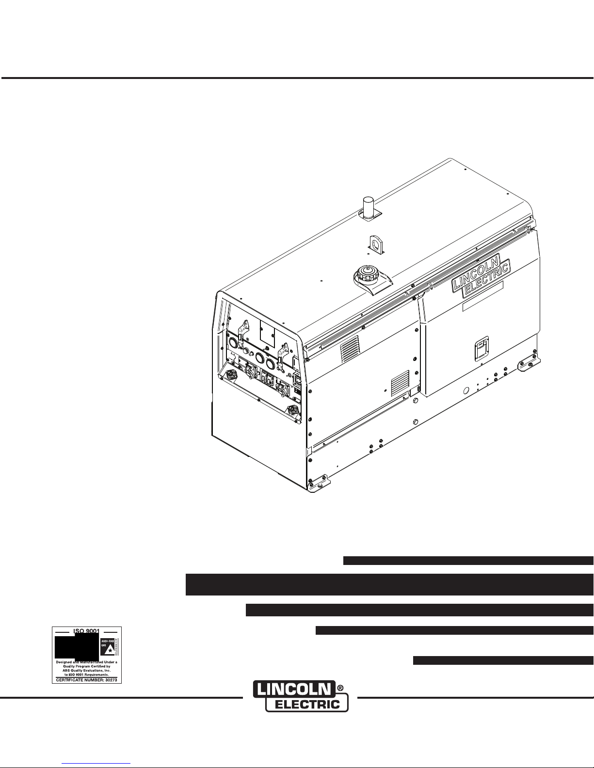
BIG RED 600
IM10019
August, 2009
For use with machines having Code Numbers:
Safety Depends on You
Lincoln arc welding and cutting
equipment is designed and built
with safety in mind. However,
your ov e r a l l s a f e t y c a n b e
increased by proper installation
... and thoughtful operation on
your part. DO NOT INSTALL,
OPERATE OR REPAIR THIS
EQUIPMENT WITHOUT READING THIS MANUAL AND THE
SAFETY PRECAUTIONS CONTAINED THROUGHOUT. And,
most importantly, think before
you act and be careful.
11599
OPERATOR’S MANUAL
• World's Leader in Welding and Cutting Products •
• Sales and Service through Subsidiaries and Distributors Worldwide •
Cleveland, Ohio 44117-1199 U.S.A. TEL: 216.481.8100 FAX: 216.486.1751 WEB SITE: www.lincolnelectric.com
Copyright © Lincoln Global Inc.
Page 2
i
SAFETY
WARNING
CALIFORNIA PROPOSITION 65 WARNINGS
Diesel engine exhaust and some of its constituents
are known to the State of California to cause cancer, birth defects, and other reproductive harm.
The Above For Diesel Engines
ARC WELDING CAN BE HAZARDOUS. PROTECT YOURSELF AND OTHERS FROM POSSIBLE SERIOUS INJURY OR DEATH.
KEEP CHILDREN AWAY. PACEMAKER WEARERS SHOULD CONSULT WITH THEIR DOCTOR BEFORE OPERATING.
Read and understand the following safety highlights. For additional safety information, it is strongly recommended that you
purchase a copy of “Safety in Welding & Cutting - ANSI Standard Z49.1” from the American Welding Society, P.O. Box
351040, Miami, Florida 33135 or CSA Standard W117.2-1974. A Free copy of “Arc Welding Safety” booklet E205 is available
from the Lincoln Electric Company, 22801 St. Clair Avenue, Cleveland, Ohio 44117-1199.
BE SURE THAT ALL INSTALLATION, OPERATION, MAINTENANCE AND REPAIR PROCEDURES ARE
PERFORMED ONLY BY QUALIFIED INDIVIDUALS.
The engine exhaust from this product contains
chemicals known to the State of California to cause
cancer, birth defects, or other reproductive harm.
The Above For Gasoline Engines
i
FOR ENGINE
powered equipment.
1.a. Turn the engine off before troubleshooting and maintenance
work unless the maintenance work requires it to be running.
____________________________________________________
1.b. Operate engines in open, well-ventilated
areas or vent the engine exhaust fumes
outdoors.
____________________________________________________
1.c. Do not add the fuel near an open flame
welding arc or when the engine is running.
Stop the engine and allow it to cool before
refueling to prevent spilled fuel from vaporizing on contact with hot engine parts and
igniting. Do not spill fuel when filling tank. If
fuel is spilled, wipe it up and do not start
engine until fumes have been eliminated.
____________________________________________________
1.d. Keep all equipment safety guards, covers and devices in
position and in good repair.Keep hands, hair, clothing and
tools away from V-belts, gears, fans and all other moving
parts when starting, operating or repairing equipment.
____________________________________________________
1.e. In s ome ca ses it ma y be nece ssary to re mov e safety
gu a r d s t o perfo r m requ i r e d m a i ntena n c e . R e m ove
guards only when necessary and replace them when the
ma i n t e nance requ i r i n g th e ir re m oval is co m plete .
Always use the greatest care when working near moving
parts.
___________________________________________________
1.f. Do not put your hands near the engine fan.
Do not attempt to override the governor or
idler by pushing on the throttle control rods
while the engine is running.
1.h. To avoid scalding, do not remove the
radiator pressure cap when the engine is
hot.
ELECTRIC AND
MAGNETIC FIELDS
may be dangerous
2.a. Electric current flowing through a ny cond uc to r cau se s
localized Electric and Magnetic Fields (EMF). Welding
current creates EMF fields aro un d w el di ng cables and
welding machines
2.b. EMF fi elds m ay int er fere w ith some pa cemak ers, a nd
welders having a pacemaker should consult their physician
before welding.
2.c. Exposure to EMF fields in welding may have other health
effects which are now not known.
2.d. All welders should use the following procedures in order to
minimize exposure to EMF fields from the welding circuit:
2.d.1.
Route the electrode and work cables together - Secure
them with tape when possible.
2.d.2. Ne ver coil th e ele ctrod e lead around yo ur bod y.
2.d.3. Do not place your body between the electrode and
work cables. If the electrode cable is on your right
side, the work cable should also be on your right side.
___________________________________________________
1.g. To prevent accidentally starting gasoline engines while
turning the engine or welding generator during maintenance
work, disconnect the spark plug wires, distributor cap or
magneto wire as appropriate.
2.d.4. Connect the work cable to the workpiece as close as
possible to the area being welded.
2.d.5. Do not work next to welding power source.
Mar ‘95
Page 3
ii
SAFETY
ii
ELECTRIC SHOCK can
kill.
3.a. The electrode and work (or ground) circuits
are electrically “hot” when the welder is on.
Do not touch these “hot” parts with your bare
skin or wet clothing . W ear dry , h ole-free
gloves to insulate hands.
3.b. Insulate yourself from work and ground using dry insulation.
Make certain the insulation is large enough to cover your full
area of physical contact with work and ground.
In addition to the normal safety precautions, if welding
mu s t be perfor med un der el ectrica l ly ha z ardous
conditions (in damp locations or while wearing wet
clothing; on metal structures such as floors, gratings or
scaffolds; when in cramped positions such as sitting,
kneeling or lying, if there is a high risk of unavoidable or
accidental contact with the workpiece or ground) use
the following equipment:
• Semiautomatic DC Constant Voltage (Wire) Welder.
• DC Manual (Stick) Welder.
• AC Welder with Reduced Voltage Control.
3.c. In semiautomatic or automatic wire welding, the electrode,
electrode reel, welding head, noz zl e or semiaut om at ic
welding gun are also electrically “hot”.
3.d. Always be sure the work cable makes a good electrical
connection with the metal being welded. The connection
should be as close as possible to the area being welded.
3.e. Ground the work or metal to be welded to a good electrical
(earth) ground.
3.f.
Maintain the electrode holder, work clamp, welding cable and
welding machine in good, safe operating condition. Replace
damaged insulation.
3.g. Never dip the electrode in water for cooling.
3.h. Nev er s imu lta neo usly t ouc h elec tri cal ly “ hot ” part s of
electrode holders connected to two welders because voltage
between the two can be the total of the open circuit voltage
of both welders.
3.i. When working above floor level, use a safety belt to protect
yourself from a fall should you get a shock.
3.j. Also see Items 6.c. and 8.
ARC RAYS can burn.
4.a. Use a shield with the proper filter and cover
plates to protect your eyes from sparks and
the rays of the arc when welding or observing
open arc welding. Headshield and filter lens
should conform to ANSI Z87. I standards.
4.b. Use suitable clothing made from durable flame-resistant
material to protect your skin and that of your helpers from
the arc rays.
4.c. Protect other nearby personnel with suitable, non-flammable
screening and/or warn them not to watch the arc nor expose
themselves to the arc rays or to hot spatter or metal.
FUMES AND GASES
can be dangerous.
5.a. Weldin g may produce fumes and gases
hazardous to health. Avoid breathing these
fumes a nd ga ses. When w el ding, keep
your head out of the fume. Use enough
ventilation and/or exhaust at the arc to keep
fumes and gases away from the breathing zone. When
we l ding with elec trodes whic h r e quire spec i al
ve n tilati on such as st ainles s or hard fac ing (see
instru ctio ns on container or MS DS) or on lead or
cadmium plated steel and other metals or coatings
which produce highly toxic fumes, keep exposure as
low as possible and within applicable OSHA PEL and
ACGIH TLV limits using local exhaust or mechanical
ventilation. In confined spaces or in some circumst a nces, outd o ors, a resp i rator may be requir e d.
Additional precautions are also required when welding
on galvanized steel.
5. b. The operation of welding fume control equipment is affected
by various factors including proper use and positioning of
the equipment, maintenance of the equipment and the specific welding procedure and application involved. Worker
exposure level should be checked upon installation and
periodically thereafter to be certain it is within applicable
OSHA PEL and ACGIH TLV limits.
5.c.
Do not weld in locations near chlorinated hydrocarbon
coming from degreasing, cleaning or spraying operations.
The heat and rays of the arc can react with solvent vapors
form phosgene, a highly toxic gas, and other irritating products.
5.d. Shielding gases used for arc welding can displace air and
caus e injury or deat h. Alw ays use eno ugh vent ilation ,
especially in confined areas, to insure breathing air is safe.
vapors
to
5.e. Read and understand the manufacturer’s instructions for this
equipment and the consumables to be used, including the
ma t e r i al safe t y d a ta shee t ( M S D S) and fo l l o w your
employer’s safety practices. MSDS forms are available from
yo u r w e lding d i s tribut o r o r from t h e m anufa c t u rer.
5.f. Also see item 1.b.
Jan ‘09
Page 4
iii
SAFETY
iii
WELDING and CUTTING
SPARKS can
cause fire or explosion.
6.a.
Remove fire hazards from the welding area.
If this is not possible, cover them to prevent
Re m e m b er th a t w eldin g s p arks an d h ot
materials from welding can easily go through small cracks
an d op enin gs t o ad j ace nt areas . Av oid wel d ing nea r
hydraulic lines. Have a fire extinguisher readily available.
6.b. Where compressed gases are to be used at the job site,
special precautions should be used to prevent hazardous
situations. Refer to “Safety in Welding and Cutting” (ANSI
Standard Z49.1) and the operating informati on for the
equipment being used.
6.c. When not welding, make certain no part of the electrode
circuit is touching the work or ground. Accidental contact
can cause overheating and create a fire hazard.
6.d. Do not heat, cut or weld tanks, drums or containers until the
proper steps have been taken to insure that such procedures
will not cause flammable or toxic vapors from substances
inside. They can cause an explosion even
been “cleaned”. For information, purchase “Recommended
Safe Practices for the
Co n t a i ners a n d Pipi n g That H a v e Hel d H a zardo u s
Substances”, AWS F4.1 from the American Welding Society
(see address above).
6.e. Vent hollow castings or containers before heating, cutting or
welding. They may explode.
Sparks and spatter are thrown from the welding arc. Wear oil
6.f.
free protective garments such as leather gloves, heavy shirt,
cuffless trousers, high shoes and a cap over your hair. Wear
ear plugs when welding out of position or in confined places.
Always wear safety glasses with side shields when in a
welding area.
6.g. Connect the work cable to the work as close to the welding
area as practical. Work cables connected to the building
framework or other locations away from the welding area
increase the possibility of the welding current pas si ng
through lifting chains, crane cables or other alternate circuits. This can create fire hazards or overheat lifting chains
or cables until they fail.
6.h. Also see item 1.c.
the w elding s parks from st arting a fi re.
though
they have
Preparation
for Welding and Cutting of
CYLINDER may explode
if damaged.
7.a. U se o n ly c o m press e d ga s c y l inder s
containing the correct shielding gas for the
pr o c e s s u s e d a n d p r o p erly opera t i n g
re g u l a tors desi g n e d fo r th e ga s an d
pressure used. All hoses, fittings, etc. should be suitable for
the application and maintained in good condition.
7.b. Alw ays keep cy linde rs i n an uprigh t positi on sec urely
chained to an undercarriage or fixed support.
7.c. Cylinders should be located:
• Away from areas where they may be struck or subjected to
physical damage.
• A safe distance from arc welding or cutting operations and
any other source of heat, sparks, or flame.
7.d. Never allow the electrode, electrode holder or any other
electrically “hot” parts to touch a cylinder.
7.e. Keep your head and face away from the cylinder valve outlet
when opening the cylinder valve.
7.f. Valve protection caps should always be in place and hand
tight except when the cylinder is in use or connected for
use.
7.g. Read an d fo llo w th e inst ruct ion s on co mpr essed gas
cylinders, associated equipment, and CGA publication P-l,
“Precautions for Safe Handling of Compressed Gases in
Cylinders,” available from the Compressed Gas Association
1235 Jefferson Davis Highway, Arlington, VA 22202.
FOR ELECTRICALLY
powered equipment.
8.a. Turn off input power using the disconnect
switch at the fuse box before working on
the equipment.
8.b. Install equipmen t in accordance with the U.S . National
Electrical Code, all local codes a nd the manufacturer’s
recommendations.
8.c. Ground the equipment in accordance with the U.S. National
Electrical Code and the manufacturer’s recommendations.
6.I. Read and follow NFPA 51B “ Standard for Fire Prevention
During Welding, Cutting and Other Hot Work”, available
from NFPA, 1 Batterymarch Park, PO box 9101, Quincy, Ma
022690-9101.
6.j. Do not use a welding power source for pipe thawing.
Refer to http://www.lincolnelectric.com/safety for additional safety information.
Jan ‘09
Page 5

iv
SAFETY
iv
PRÉCAUTIONS DE SÛRETÉ
Pour votre propre protection lire et observer toutes les instructions
et les précautions de sûreté specifiques qui parraissent dans ce
manuel aussi bien que les précautions de sûreté générales suivantes:
Sûreté Pour Soudage A L’Arc
1. Protegez-vous contre la secousse électrique:
a. Les circuits à l’électrode et à la piéce sont sous tension
quand la machine à souder est en marche. Eviter toujours
tout contact entre les parties sous tension et la peau nue
ou les vétements mouillés. Porter des gants secs et sans
trous pour isoler les mains.
b. Faire trés attention de bien s’isoler de la masse quand on
soude dans des endroits humides, ou sur un plancher
metallique ou des grilles metalliques, principalement dans
les positions assis ou couché pour lesquelles une grande
partie du corps peut être en contact avec la masse.
c. Maintenir le porte-électrode, la pince de masse, le câble
de soudage et la machine à souder en bon et sûr état
defonctionnement.
d.Ne jamais plonger le porte-électrode dans l’eau pour le
refroidir.
e. Ne jamais toucher simultanément les parties sous tension
des porte-électrodes connectés à deux machines à souder
parce que la tension entre les deux pinces peut être le
total de la tension à vide des deux machines.
f. Si on utilise la machine à souder comme une source de
courant pour soudage semi-automatique, ces precautions
pour le porte-électrode s’applicuent aussi au pistolet de
soudage.
2. Dans le cas de travail au dessus du niveau du sol, se protéger
contre les chutes dans le cas ou on recoit un choc. Ne jamais
enrouler le câble-électrode autour de n’importe quelle partie
du corps.
5. Toujours porter des lunettes de sécurité dans la zone de
soudage. Utiliser des lunettes avec écrans lateraux dans les
zones où l’on pique le laitier.
6. Eloigner les matériaux inflammables ou les recouvrir afin de
prévenir tout risque d’incendie dû aux étincelles.
7. Quand on ne soude pas, poser la pince à une endroit isolé de
la masse. Un court-circuit accid en ta l p eu t p ro voquer un
échauffement et un risque d’incendie.
8. S’assurer que la masse est connectée le plus prés possible
de la zone de travail qu’il est pratique de le faire. Si on place
la masse sur la charpente de la construction ou d’autres
endroits éloignés de la zone de travail, on augmente le risque
de voir passer le courant de soudage par les chaines de levage, câbles de grue, ou autres circuits. Cela peut provoquer
des risques d’incendie ou d’echauffement des chaines et des
câbles jusqu’à ce qu’ils se rompent.
9. Assurer une ventilation suffisante dans la zone de soudage.
Ceci est particuliérement important pour le soudage de tôles
galvanisées plombées, ou cadmiées ou tout autre métal qui
produit des fumeés toxiques.
10. Ne pas souder en présence de vapeurs de chlore provenant
d’o pérations de dégraissage, n ettoyage ou pistolage. La
chaleur ou les rayons de l’arc peuvent réagir avec les vapeurs
du solvant pour produire du phosgéne (gas fortement toxique)
ou autres produits irritants.
11. Pour obtenir de plus amples renseignements sur la sûreté,
voir le code “Code for safety in welding and cutting” CSA
Standard W 117.2-1974.
PRÉCAUTIONS DE SÛRETÉ POUR
3. Un coup d’arc peut être plus sévère qu’un coup de soliel,
donc:
a. Utiliser un bon masque avec un verre filtrant approprié
ainsi qu’un verre blanc afin de se protéger les yeux du rayonnement de l’arc et des projections quand on soude ou
quand on regarde l’arc.
b. Porter des vêtements convenables afin de protéger la
peau de soudeur et des aides contre le rayonnement de
l‘arc.
c. Protéger l’au tre personnel t ravaillan t à pr oximité au
soudage à l’aide d’écrans appropriés et non-inflammables.
4. Des gouttes d e laitier en f usion sont émises de l’a rc de
soudage. Se protéger avec des vêtements de protection libres
de l’huile, tels que les gants en cuir, chemise épaisse, pantalons sans revers, et chaussures montantes.
LES MACHINES À SOUDER À
TRANSFORMATEUR ET À
REDRESSEUR
1. Relier à la terre le chassis du poste conformement au code de
l’électricité et aux recommendations du fabricant. Le dispositif
de montage ou la piece à souder doit être branché à une
bonne mise à la terre.
2. Autant que possible, I’installation et l’entretien du poste seront
effectués par un électricien qualifié.
3. Avant de faires des travaux à l’interieur de poste, la debrancher à l’interrupteur à la boite de fusibles.
4. Garder tous les couvercles et dispositifs de sûreté à leur
place.
Mar. ‘93
Page 6

Thank You
vv
for selecting a QUALITY product by Lincoln Electric. We want you
to take pride in operating this Lincoln Electric Company product
••• as much pride as we have in bringing this product to you!
The business of The Lincoln Electric Company is manufacturing and selling high quality welding equipment, consumables, and cutting equipment. Our challenge is to meet the needs of our customers and to exceed their expectations. On occasion, purchasers may ask Lincoln
Electric for advice or information about their use of our products. We respond to our customers based on the best information in our possession at that time. Lincoln Electric is not in a position to warrant or guarantee such advice, and assumes no liability, with respect to such information or advice. We expressly disclaim any warranty of any kind, including any warranty of fitness for any customer’s particular purpose,
with respect to such information or advice. As a matter of practical consideration, we also cannot assume any responsibility for updating or
correcting any such information or advice once it has been given, nor does the provision of information or advice create, expand or alter any
warranty with respect to the sale of our products.
Lincoln Electric is a responsive manufacturer, but the selection and use of specific products sold by Lincoln Electric is solely within the control
of, and remains the sole responsibility of the customer. Many variables beyond the control of Lincoln Electric affect the results obtained in
applying these types of fabrication methods and service requirements.
Subject to Change – This information is accurate to the best of our knowledge at the time of printing. Please refer to www.lincolnelectric.com
for any updated information.
CUSTOMER ASSISTANCE POLICY
Please Examine Carton and Equipment For Damage Immediately
When this equipment is shipped, title passes to the purchaser upon receipt by the carrier. Consequently, Claims
for material damaged in shipment must be made by the purchaser against the transportation company at the
time the shipment is received.
Please record your equipment identification information below for future reference. This information can be
found on your machine nameplate.
Product _________________________________________________________________________________
Model Number ___________________________________________________________________________
Code Number or Date Code_________________________________________________________________
Serial Number____________________________________________________________________________
Date Purchased___________________________________________________________________________
Where Purchased_________________________________________________________________________
Whenever you request replacement parts or information on this equipment, always supply the information you
have recorded above. The code number is especially important when identifying the correct replacement parts.
On-Line Product Registration
- Register your machine with Lincoln Electric either via fax or over the Internet.
• For faxing: Complete the form on the back of the warranty statement included in the literature packet
accompanying this machine and fax the form per the instructions printed on it.
• For On-Line Registration: Go to our
“Product Registration”. Please complete the form and submit your registration.
Read this Operators Manual completely before attempting to use this equipment. Save this manual and keep it
handy for quick reference. Pay particular attention to the safety instructions we have provided for your protection.
The level of seriousness to be applied to each is explained below:
WEB SITE at www.lincolnelectric.com. Choose “Quick Links” and then
WARNING
This statement appears where the information must be followed exactly to avoid serious personal injury or loss of life.
CAUTION
This statement appears where the information must be followed to avoid minor personal injury or damage to this equipment.
Page 7

vi
TABLE OF CONTENTS
Page
Installation.......................................................................................................................Section A
Technical Specifications.......................................................................................................A-1
Safety Precautions........................................................................................................A-2
Location and Ventilation................................................................................................A-2
Storing...........................................................................................................................A-2
Stacking ........................................................................................................................A-2
Angle of Operation ........................................................................................................A-2
Lifting.............................................................................................................................A-2
High Altitude Operation.................................................................................................A-2
High temperature Operation..........................................................................................A-2
Towing...........................................................................................................................A-3
Vehicle Mounting...........................................................................................................A-3
Pre-Operation Engine Service..............................................................................................A-3
Oil..................................................................................................................................A-3
Fuel ...............................................................................................................................A-3
Engine Break-In ............................................................................................................A-4
Engine Coolant..............................................................................................................A-4
Battery Connection........................................................................................................A-4
Muffler Outlet Pipe ........................................................................................................A-5
Spark Arrester ...............................................................................................................A-5
Welding Output Cables ........................................................................................................A-5
Auxiliary Power Receptacles, Residual Device Ready, Standby Power Connections .........A-6
Connection of Lincoln Electric Wire Feeders .......................................................................A-7
________________________________________________________________________________
vi
Operation.........................................................................................................................Section B
Safety Instructions................................................................................................................B-1
General Description..............................................................................................................B-1
Recommended Applications.................................................................................................B-1
Controls and Settings ..................................................................................................................B-2
Welder Controls ............................................................................................................B-2
Engine Controls.............................................................................................................B-3
Auxiliary.........................................................................................................................B-3
Engine Operation .................................................................................................................B-4
Starting the Engine........................................................................................................B-4
Cold Weather Starting and Operation ...........................................................................B-4
Stoping the Engine........................................................................................................B-4
Welding Operation................................................................................................................B-5
Stick ..............................................................................................................................B-5
Arc Gouging ..................................................................................................................B-5
TIG Welding ..................................................................................................................B-6
Constant Current Operation with Lincoln Wire Feeder .................................................B-7
Auxiliary Power.....................................................................................................................B-8
Simultaneous Welding and Power Loads .....................................................................B-8
________________________________________________________________________________
Accessories.....................................................................................................Section C
Optional Features ..................................................................................................C-1
________________________________________________________________________
Page 8

TABLE OF CONTENTS
Page
Maintenance ....................................................................................................Section D
Safety Precautions ................................................................................................D-1
Routine and Periodic Engine Maintenance ...........................................................D-1
Oil Filter Change .............................................................................................D-2
Air Filter Change .............................................................................................D-2
Fuel and Bleeding the Fuel System ................................................................D-2
Fuel Filters ......................................................................................................D-3
Fuel Pre-Filter/Water Separator Assembly .....................................................D-3
Water Separator Element ...............................................................................D-3
Second Fuel Filter ...........................................................................................D-4
Cooling System ...............................................................................................D-4
Cooling Blower Belt.........................................................................................D-4
Battery Handling ...............................................................................D-4 thru D-5
Servicing Optional Spark Arrestor .........................................................................D-5
Nameplates / Warning Decals ........................................................................D-5
Welder / Generator Maintenance ..........................................................................D-6
Storage ...........................................................................................................D-6
Cleaning..........................................................................................................D-6
Brush Removal and Replacement ..................................................................D-6
GFCI Module Testing and Resetting Procedure .............................................D-6
________________________________________________________________________
viivii
Troubleshooting..............................................................................................Section E
Safety Precautions.................................................................................................E-1
How to Use Troubleshooting Guide.......................................................................E-1
Troubleshooting Guide...................................................................................E-2, E-3
________________________________________________________________________
Diagrams ..........................................................................................................Section F
Instructions for Installing a Residual Current Device......................................F-1, F-2
Wiring Diagram ......................................................................................................F-3
Dimension Print......................................................................................................F-4
________________________________________________________________________
Parts List...................................................................................................P-619 SERIES
________________________________________________________________________
Page 9
A-1
INSTALLATION
A-1
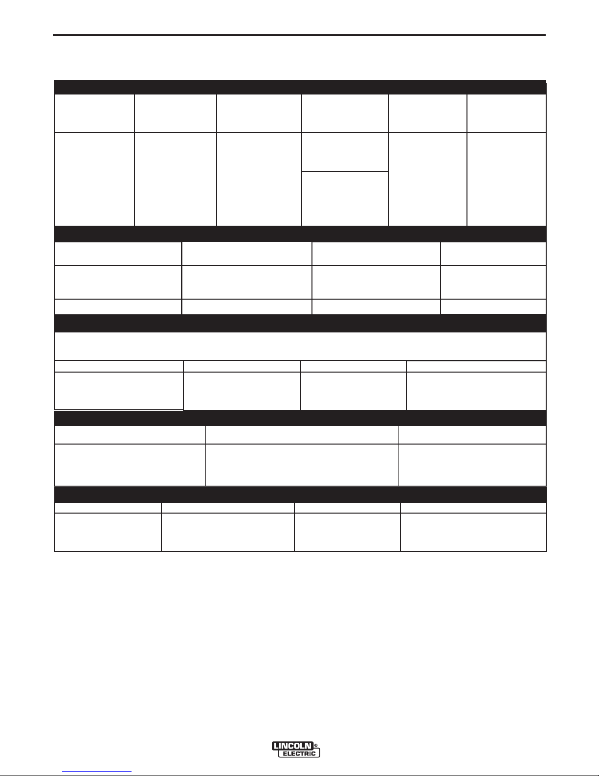
TECHNICAL SPECIFICATIONS - BIG RED™ 600
(K2811-1)
INPUT - DIESEL ENGINE
Make/Model Description Speed (RPM) Displacement Starting Capacities
System
Deutz 3 cylinder Idle 1890 173 cu. in 12VDC battery Fuel
F3L 912 44HP (33 kw) (2.83L) & Starter (20 US gal)
Diesel Engine @ 1800 RPM Full Load 1800 75.7L
Bore x Stroke
Oil:
3.94” x 4.72” 9.5 QTS.
(100mm x 120mm) 9.0L
RATED OUTPUT @ 104° F (40° C) - WELDER
Welding Process
DC Constant Current
TIG
Welding Output
Current/Voltage/Duty Cycle
500A / 40V / 100%
550A / 34V / 60%
600A / 30V / 40%
250A / 20V / 100%
Output Range
Amps
65A TO 600A
65A TO 250A
Max. Weld OCV
Voltage @ 1800RPM
90 Volts
75 Volts
RATED OUTPUT @ 104° F (40° C).- GENERATOR
1
AMPS
20
15
15
POWER
2400 Watts
1800 Watts
3600 Watts
OUTLETS
1
1
1
Auxiliary Power
Single Phase 60 Hz AC
VOLTS
120
120
240
RECEPTACLES AND CIRCUIT BREAKERS
RECEPTACLES AUXILIARY POWER CIRCUIT BREAKER OTHER CIRCUIT BREAKERS
1 - 120VAC Duplex NEMA(5-20R) GFCI protected
1 - 120VAC European (IEC-309)-GFCI protected
1 - 240VAC European (IEC-309)
1 - 20 AMP for 120 VAC Duplex (NEMA)
1 - 15 AMP for 120 VAC
1 - 15 AMP for 240 VAC
European (IEC-309)
European (IEC-309)
20AMP for Battery Charging Circuit
PHYSICAL DIMENSIONS
HEIGHT WIDTH DEPTH WEIGHT
(2)
36.87
916.5 mm 718.3 mm 1653.5 mm
1. Output rating in watts is equivalent to volt-amperes at unity power factor. Output voltage is within ± 10% at all loads up to
rated capacity. When welding, available auxiliary power will be reduced.
2. To Top of enclosure, add 8.28”(210.1mm) to top of exhaust pipe.
in. 28.28 in 65.1 in.
1657 lbs. (752 kg.)
BIG RED™ 600
Page 10
A-2
INSTALLATION
A-2
SAFETY PRECAUTION
Read this entire installation section before you start
installation.
WARNING
ELECTRIC SHOCK can kill.
• Do not touch electrically live parts or
electrode with skin or wet clothing.
• Insulate yourself from work and
ground
• Always wear dry insulating gloves.
------------------------------------------------------------------------
ENGINE EXHAUST can kill.
• Use in open, well ventilated areas or
vent exhaust outside.
------------------------------------------------------------------------
MOVING PARTS can injure.
• Do not operate with doors open or
guards off.
• Stop engine before servicing.
• Keep away from moving parts.
------------------------------------------------------------------------
See additional warning information at
front of this operator’s manual.
LOCATION AND VENTILATION
The welder should be located to provide an unrestricted flow of clean, cool air to the cooling air inlets and to
avoid restricting the cooling air outlets. Also, locate the
welder so that the engine exhaust fumes are properly
vented to an outside area.
STORING
ANGLE OF OPERATION
To achieve optimum engine performance the BIG
RED™ 600 should be run in a level position. The
maximum angle of operation for the Deutz engine is
30 degrees fore and aft, 40 degrees right and 45
degrees left. If the engine is to be operated at an
angle, provisions must be made for checking and
maintaining the oil level at the normal (FULL) oil
capacity in the crankcase. When operating the welder
at an angle, the effective fuel capacity will be slightly
less than the amount specified.
LIFTING
The BIG RED™ 600 weighs approximately 1772lbs.
(804kg.) with a full tank of fuel 1657lbs.(752kg) less
fuel. A lift bail is mounted to the machine and should
always be used when lifting the machine.
WARNING
• Lift only with equipment of adequate lifting capacity.
• Be sure machine is stable when lifting.
• Do not lift this machine using lift
bail if it is equipped with a heavy
accessory such as trailer or gas
cylinder.
FALLING • Do not lift machine if lift bail is
EQUIPMENT can damaged.
cause injury. • Do not operate machine while
suspended from lift bail.
--------------------------------------------------------------------------------
1. Store the machine in a cool, dry place when it is
not in use. Protect it from dust and dirt. Keep it
where it can’t be accidentally damaged from construction activities, moving vehicles, and other
hazards.
2. Drain the engine oil and refill with fresh 10W30
oil. Run the engine for about five minutes to circulate oil to all the parts. See the MAINTENANCE section of this manual for details on
changing oil.
3. Remove the battery, recharge it, and adjust the
electrolyte level. Store the battery in a dry, dark
place.
STACKING
BIG RED™ 600 machines cannot be stacked.
HIGH ALTITUDE OPERATION
At higher altitudes, output derating may be necessary.
For maximum rating, derate the welder output 5% for
every 300 meters (984 ft.) above 1500 meters (4920
ft.). For output of 500A and below, derate the welder
output 5% for every 300 meters (984 ft.) above 2100
meters (6888 ft.).
Contact a Deutz Service Representative for any
engine adjustments that may be required.
HIGH TEMPERATURE OPERATION
WELDER OUTPUT RATINGS AT
TEMPERATURES ABOVE 40°C
AMPS DUTY CYCLE VOLTS TEMPERATURE
450 DC 30% 38 55°C
500 DC 30% 40 50°C
550 DC 30% 34 45°C
BIG RED™ 600
Page 11
A-3
INSTALLATION
A-3
TOWING
Use a recommended trailer for use with this equipment for road, in-plant and yard towing by a vehicle(1). If the user adapts a non-Lincoln trailer, he must
assume responsibility that the method of attachment
and usage does not result in a safety hazard or damage the welding equipment. Some of the factors to be
considered are as follows:
1. Design capacity of trailer vs. weight of Lincoln
equipment and likely additional attachments.
2. Proper support of, and attachment to, the base of
the welding equipment so there will be no undue
stress to the framework.
3. Proper placement of the equipment on the trailer to
insure stability side to side and front to back when
being moved and when standing by itself while
being operated or serviced.
4. Typical conditions of use, i.e., travel speed; rough-
ness of surface on which the trailer will be operated; environmental conditions; like maintenance.
5. Conformance with federal, state and local laws.
(1) Consult applicable federal, state and local laws regarding spe-
cific requirements for use on public highways.
(1)
VEHICLE MOUNTING
WARNING
Improperly mounted concentrated loads may
cause unstable vehicle handling and tires or other
components to fail.
• Only transport this Equipment on serviceable
vehicles which are rated and designed for such
loads.
• Distribute, balance and secure loads so vehicle
is stable under conditions of use.
• Do not exceed maximum rated loads for components such as suspension, axles and tires.
• Mount equipment base to metal bed or frame of
vehicle.
• Follow vehicle manufacture’s instructions.
------------------------------------------------------------------------
PRE-OPERATION ENGINE SERVICE
READ the engine operating and maintenance instructions supplied with this machine.
WARNING
Stop engine while fueling.
• Do not smoke when fueling.
• Keep sparks and flame away
from tank.
• Do not leave unattended while
fueling.
DIESEL FUEL
can cause fire.
• Wipe up spilled fuel and allow
fumes to clear before starting
engine.
• Do not overfill tank, fuel expansion may cause overflow.
DIESEL FUEL ONLY
------------------------------------------------------------------------------------------
OIL
The BIG RED™ 600 is shipped with the engine
crankcase filled with high quality SAE 10W-30 oil (API
class CD or better). Check the oil level before starting
the engine. If it is not up to the full mark on the dip
stick, add oil as required. Check the oil level every
four hours of running time during the first 35 running
hours. Refer to the engine Operator’s Manual for specific oil recommendations and break-in information.
The oil change interval is dependent on the quality of
the oil and the operating environment. Refer to the
engine Operator’s Manual for the proper service and
maintenance intervals. The machine is equipped with
an oil drain valve.
FUEL
USE DIESEL FUEL ONLY
WARNING
• Fill the fuel tank with clean, fresh fuel. The
capacity of the tank is 20 gals. (75.7 ltrs). When
the fuel gauge reads empty the tank contains
approximately 2 gals. (7.6ltrs.) of reserve fuel.
WARNING
NOTE: A fuel shut off valve is located on the pre-
filter/sediment filter. Which should be in
the closed position when the welder is not
used for extended periods of time.
------------------------------------------------------------------------
BIG RED™ 600
Page 12

A-4
INSTALLATION
A-4
ENGINE BREAK-IN
Lincoln Electric selects high quality, heavy-duty industrial engines for the portable welding machines we
offer. While it is normal to see a small amount of
crankcase oil consumption during initial operation,
excessive oil use, wetstacking (oil or tar like substance at the exhaust port), or excessive smoke is not
normal.
Larger machines with a capacity of 350 amperes and
higher, which are operated at low or no-load conditions for extended periods of time are especially susceptible to the conditions described above. To
accomplish successful engine break-in, most dieselpowered equipment needs only to be run at a reasonably heavy load within the rating of the welder for
some period of time during the engine’s early life.
However, if the welder is subjected to extensive light
loading, occasional moderate to heavy loading of the
engine may sometimes be necessary. Caution must
be observed in correctly loading a diesel/generator
unit.
1. Connect the welder output studs to a suitable resistive load bank. Note that any
attempt to short the output studs by connecting the welding leads together, direct
shorting of the output studs, or connecting
the output leads to a length of steel will
result in catastrophic damage to the generator and voids the warranty.
2. Set the welder controls for an output current and voltage within the welder rating
and duty cycle. Note that any attempt to
exceed the welder rating or duty cycle for
any period of time will result in catastrophic
damage to the generator and voids the
warranty.
3. Periodically shut off the engine and check
the crankcase oil level.
ENGINE COOLING SYSTEM
The Deutz engine is air cooled by a belt driven axial
blower. The oil cooler and engine cooling fins should
be blown out with compressed air or steam to maintain proper cooling (See the engine Owners Manual
for procedures and frequency).
BATTERY CONNECTION
WARNING
GASES FROM BATTERY can explode.
• Keep sparks, flame and cigarettes
away from battery.
To prevent EXPLOSION when:
• INSTALLING A NEW BATTERY — disconnect
negative cable from old battery first and connect
to new battery last.
• CONNECTING A BATTERY CHARGER — remove
battery from welder by disconnecting negative
cable first, then positive cable and battery clamp.
When reinstalling, connect negative cable last.
Keep well ventilated.
• USING A BOOSTER — connect positive lead to
battery first then connect negative lead to negative battery lead at engine foot.
BATTERY ACID can burn eyes and skin.
• Wear gloves and eye protection and
be careful when working near battery.
• Follow instructions printed on battery.
IMPORTANT: To prevent ELECTRICAL DAMAGE
WHEN:
a) Installing new batteries.
b) Using a booster.
Use correct polarity — Negative Ground.
------------------------------------------------------------------------
The BIG RED™ 600 is shipped with the negative battery cable disconnected. Before you operate the
machine, make sure the Engine Switch is in the OFF
position and attach the disconnected cable securely to
the negative (-) battery terminal.
Remove the insulating cap from the negative battery
terminal. Replace and tighten negative battery cable
terminal.
NOTE: This machine is furnished with a wet charged
battery; if unused for several months, the battery may
require a booster charge. Be sure to use the correct
polarity when charging the battery.
BIG RED™ 600
Page 13

A-5
INSTALLATION
A-5
MUFFLER OUTLET PIPE
Remove the plastic plug covering the muffler outlet
tube. Using the clamp provided secure the outlet pipe
to the outlet tube with the pipe positioned such that it
will direct the exhaust in the desired position
.
SPARK ARRESTOR
Some federal, state or local laws may require that
petrol or diesel engines be equipped with exhaust
spark arrestors when they are operated in certain
locations where unarrested sparks may present a fire
hazard. The standard muffler included with this welder
does not qualify as a spark arrestor. When required by
local regulations, a suitable spark arrestor, must be
installed and properly maintained.
CAUTION
An incorrect arrestor may lead to damage to the
engine or adversely affect performance.
------------------------------------------------------------------------
WELDING OUTPUT CABLES
With the engine off, connect the electrode and work
cables to the output studs. The welding process dictates the polarity of the electrode cable. These connections should be checked periodically and tightened
if necessary.
Listed in Table A.1 are copper cable sizes recommended for the rated current and duty cycle. Lengths
stipulated are the distance from the welder to work
and back to the welder again. Cable sizes are
increased for greater lengths primarily for the purpose
of minimizing cable voltage drop.
Table A.1 Combined Length of Electrode and
Work Cables.
MACHINE GROUNDING
Because this portable engine driven welder creates its
own power, it is not necessary to connect its frame to
an earth ground, unless the machine is connected to
premises wiring (home, shop, etc.).
To prevent dangerous electric shock, other equipment
powered by this engine driven welder must:
a) be grounded to the frame of the welder using
a grounding type plug,
or
b) be double insulated.
When this welder is mounted on a truck or trailer, its
frame must be securely connected to the metal frame
of the vehicle. When this engine driven welder is connected to premises wiring such as that in a home or
shop, its frame must be connected to the system earth
ground. See further connection instructions in the section entitled “Standby Power Connections” as well as
the article on grounding in the latest National
Electrical Code and the local codes.
In general, if the machine is to be grounded, it should
be connected with a #8 or larger copper wire to a solid
earth ground such as a metal ground stake going into
the ground for at least 10 Feet or to the metal framework of a building which has been effectively grounded. The National Electric Code lists a number of alternate means of grounding electrical equipment. A
machine grounding stud marked with the symbol
is provided on the front of the welder.
TOTAL COMBINED LENGTH OF ELECTRODE
AMPS Upto150 ft. 150-200 ft. 200-250 ft.
@100% (Up to45m) (45-60m) (60-75m)
Duty Cycle
500 3/0 AWG 3/0 AWG 4/0 AWG
95mm
AND WORK CABLES
2
95mm
2
120mm
2
BIG RED™ 600
Page 14

A-6
INSTALLATION
AUXILIARY POWER RECEPTACLES
A-6
RESIDUAL CURRENT DEVICE READY
The auxiliary power of the BIG RED™ 600 consists of
Single Phase 60Hz Power. Out put Voltage is within
+/- 10% at loads up to rated capacity.
One 120VAC NEMA (5-20R) 20 amp duplex receptacle is protected by a 20 amp circuit breaker that provides 2400 watts Peak / 2400 watts Continuous
power. Maximum current is 20 amps total.
One 120VAC European (IEC-309) 16 amp receptacle
is protected by a 15 amp circuit breaker that provides
1800 watts Peak / 1800 watts Continuous power.
Maximum current is 15 amps.
One 240VAC European (IEC-309) 16 amp receptacle
is protected by a 15 amp 2-pole circuit breaker that
provides 3600 watts Peak / 3600 watts Continuous
power. The 2-pole circuit breaker disconnects both hot
leads at the same time. Maximum current is 15 amps.
120 V RECEPTACLES
A GFCI module protects, the two 120V Auxiliary
Power receptacles. A GFCI (Ground Fault Circuit
Interrupter) electrical receptacle is a device to protect
against electric shock should a piece of defective
equipment connected to it develop a ground fault. If
this situation should occur, the GFCI module will trip,
removing voltage from the output of the receptacle. If
a GFCI module is tripped see the MAINTENANCE
section for detailed information on testing and resetting it. A GFCI module should be properly tested at
least once every month.
The 120 V auxiliary power receptacles should only be
used with three wire grounded type plugs or approved
double insulated tools with two wire plugs. The current
rating of any plug used with the system must be at
least equal to the current capacity of the associated
receptacle.
The BIG RED™ 600 is configured to allow for the
addition of a Residual Current Device (RCD) to protect the 240V Single Phase Receptacle. The auxiliary
power area on the front panel of the BIG RED™ 600
has a hole sized and shaped to accept a typical 2-pole
(RCD) along with a protective rubber boot. A cover
plate with a label “RCD READY” covers the hole and
secures a mounting bracket on the backside of the
panel.
Note: The (RCD) should be rated for at least 15 amps.
There are many suppliers of RCD’s. One example is
Allen Bradley, part number 1492-RCD2A40.
The protective boot can be obtained from:
APM-Hexseal, part number HE-1035
See Section F Diagrams of this Operator’s Manual for
instructions on installing an RCD and protective rubber boot.
STANDBY POWER CONNECTIONS
The BIG RED™ 600 is suitable for temporary, standby
or emergency power using the engine manufacturer’s
recommended maintenance schedule.
The BIG RED™ 600 can be permanently installed as
a standby power unit for 240 VAC(60Hz). Connections
must be made by a licensed electrician who can
determine how the 120/240 VAC power can be adapted to the particular installation and comply with all
applicable electrical codes.
Take necessary steps to assure load is limited to the
capacity of the BIG RED™ 600
WARNING
• Only a licensed, certified, trained electrician
should install the machine to a premises or residential electrical system. Be certain that:
• The installation complies with the National
Electrical Code and all other applicable electrical
codes.
• The premises is isolated and no feedback into
the utility system can occur. Certain state and
local laws require the premises to be isolated
before the generator is linked to the premises.
Check your state and local requirements.
------------------------------------------------------------------------
BIG RED™ 600
Page 15

A-7
BIG RED™ 600
Work
Electrode
Workclip
LN-15™ ACROSS THE ARC
LN-25™, LN-25™ PRO
INSTALLATION
A-7
CONNECTION OF LINCOLN ELECTRIC
WIRE FEEDERS
WARNING
Shut off Welder before making any electrical connections.
------------------------------------------------------------------------
The LN-15™ Across-the-Arc model, LN-25™ with or
without an internal contactor, and LN-25™ PRO may
be used with the BIG RED™ 600.
1. Shut the welder off.
2. For electrode Positive, connect the electrode cable
from the wire feeder to the “+” terminal of the
welder and work cable to the “-” terminal of the
welder. For electrode Negative, connect the electrode cable from the wire feeder to the “-” terminal
of the welder and work cable to the “+” terminal of
the welder.
3. Set the CV/CC mode of the wire feeder to CC.
(Refer to wire feeder operator manual for details on
setting the wire feeder in the CC mode and for setting welding parameters).
WARNING
If you are using an LN-25™ without an internal
contactor, the electrode will be energized when
the BIG RED™ 600 is started.
------------------------------------------------------------------------
The Wire Feeder sensor has full OCV potential
between spring clip and w ork return. Turn
machine off when attaching spring clip.
------------------------------------------------------------------------
Lincoln Electric does NOT recommend constant
current semiautomatic welding for applications
which need to meet specified weld metal chemical
or mechanical property requirements or weld
quality requirements.
------------------------------------------------------------------------
4. Attach the single lead from the front of the wire
feeder to work using the spring clip at the end of the
lead. This is a sense lead to supply current to the
wire feeder motor; it does not carry welding current.
5. When the gun trigger is closed, the current sensing
circuit will cause the wire to begin to feed and the
welding process is started.
NOTE: The LN- 2 5 ™ (K 44 4 - 1) Re m o t e Contro l
Module (K431) and Remote Cable (K432) cannot be used with the BIG RED™ 600 See the
appropriate connection diagram in Section F.
FIGURE A-1
BIG RED™ 600
Page 16

B-1
OPERATION
B-1
SAFETY INSTRUCTIONS
Read and understand this entire section before
operating your BIG RED™ 600.
WARNING
Do not attempt to use this equipment until you
have thoroughly read all operating and maintenance manuals supplied with your machine. They
include important safety precautions, detailed
engine starting, operating and maintenance
instructions and parts lists.
ELECTRIC SHOCK can kill.
• Do not touch electrically live parts
such as output terminals or internal
wiring.
• Insulate yourself from the work and
ground.
• Always wear dry insulating gloves.
------------------------------------------------------------------------
ENGINE EXHAUST can kill.
• Use in open, well ventilated areas or
vent exhaust outside
• Do not stack anything near the engine.
------------------------------------------------------------------------
MOVING PARTS can injure.
• Do not operate with doors open or
guards off.
• Stop engine before servicing.
• Keep away from moving parts
------------------------------------------------------------------------
Only qualified personnel should operate this
equipment.
------------------------------------------------------------------------
ADDITIONAL SAFETY PRECAUTIONS
GENERAL DESCRIPTION
The BIG RED™ 600 is a diesel engine driven welder,
offering reliable DC arc welding performance, with
outstanding arc characteristics for all welding applications. The BIG RED™ 600 is both a rugged three
cylinder, diesel engine driven 600 amp DC arc welder
and 3.6 KW AC power generator. This powerful generator can be used to provide electricity for lights,
power tools, etc.
The BIG RED™ 600 delivers ideal DC arc characteristic for each welding process. Stick electrode welding,
Scratch-Start TIG, or carbon arc gouging, to make the
BIG RED™ 600 the ideal all purpose engine driven
welder for on-site work.
The BIG RED™ 600 has “no PC Boards” and “no
electronics”.
The BIG RED™ 600 is service friendly with a minimal
number of major parts, simplifying in field servicing of
the BIG RED™ 600. The generator is a dual stator
and rotor design with two sealed bearings for maintenance free service. The rotors are copper wound
design with two slip rings and brushes. The stators
are wound entirely with heavy gauge copper wire and
insulated with NEMA class F insulation material. The
stator is then impregnated with three layers of high
quality varnish. After the stator is assembled using tie
bars, the entire assembly Is covered with an environmentally protective coating . These measures insure
trouble-free operation in the harshest environments.
RECOMMENDED APPLICATIONS
WELDER
The BIG RED™ 600 provides constant current DC
welding output for stick (SMAW) and TIG (GTAW)
welding (scratch start). In addition the Big Red can be
used for Arc Gouging with carbons up to 9.5 mm
(3/8”) diameter.
Always operate the welder with the hinged door
closed and the side panels in place as these provide maximum protection from moving parts and
insure proper cooling air flow.
------------------------------------------------------------------------
The BIG RED™ 600 is not recommended
thawing.
GENERATOR
The BIG RED™ 600 provides smooth output for auxiliary
power and emergency standby power. The auxiliary power
is independent of the welding power and thus not effected
by the weld control settings. Full power is available provided
welding output is below 200 amps. Above 200 amps refer to
the Simultaneous Welding and Auxiliary Power chart in the
operation section of this manual.
BIG RED™ 600
for pipe
Page 17

B-2
3
1
9
4
8
7
11
12
2
14
13
21
5
6
10
15
16
17
18
19
20
22
CONTROLS AND SETTINGS
All welder and engine controls are located on the case front panel. Refer to Figure B.1 and the explanations that follow.
Figure B.1 Case Front Panel Controls
OPERATION
B-2
WELDING CONTROLS (Items 1-5)
1. OUTPUT RANGE SELECTOR SWITCH
A 5 position switch that provides 5 overlapping output current settings:
• 65 - 115
• 105 - 220
• 150 - 330
• 200 - 435
• 300 – Maximum
Note: Do not switch while welding
BIG RED™ 600
2. OUTPUT CONTROL
Provides fine adjustment of the current and open
circuit voltage from minimum to maximum within
each Range.
“1’’ is minimum and “10” is maximum.
3. WELD MODE SELECTOR SWITCH
Provides selection of either Stick / Arc Gouging
Mode or TIG Mode.
4. VOLT/AMP METERS (optional)
Optional analog volt and amp meter kit available for
easy installation into front panel.
(See Accessory Section For “K” number)
Page 18

B-3
5. LOCAL / REMOTE CONTROL SWITCH and
REMOTE RECEPTACLE
OPERATION
B-3
11. OIL PRESSURE GAUGE
An indicator of engine oil pressure.
The toggle switch provides the option of controlling
the welding output at the control panel or remotely.
For control at the control panel set the switch in the
"LOCAL" position. For remote control set the switch
in the "REMOTE" position. The receptacle is for
attaching an optional remote control equipment.
(See Accessory Section For “K” number)
ENGINE CONTROLS (Items 6 Through to 13)
6. ENGINE HOUR METER / FUEL GAUGE
Combination hour meter fuel level gauge. The hour
meter displays the total time that the engine has
been running. This meter is a useful indicator for
scheduling preventive maintenance. The fuel gauge
displays the level of diesel fuel in the fuel tank. The
operator must watch the fuel level closely to prevent running out of fuel and possibly having to
bleed the system.
7. RUN STOP SWITCH
The RUN position energizes the hold coil of the fuel
solenoid, hour meter, and rotor flashing circuit. The
STOP position stops the engine.
Note: Do not leave switch in RUN position when the
engine is not running. In the RUN position the
battery will be discharged.
12. ENGINE PROTECTION
A warning indicator light for high oil temperature or
low oil pressure. The light remains off with proper
oil temperature and proper oil pressure. If a fault is
detected the light will turn on and the engine protection system will stop the engine. The light will
remain on when the engine has been shut down.
In order to try and re-start the engine the engine
protection system must be reset by returning the
RUN-STOP switch to the STOP position.
Note: The light remains off when the RUN-STOP
switch is in the RUN position prior to starting the
engine. However if the engine is not started within
60 seconds the light will come on. When this happens the RUN-STOP switch must be returned to
the STOP position to reset the engine protection
system and light.
13. BATTERY CHARGING LIGHT
An indicator light for low/no battery charging. The
light is off when the battery charging system is
functioning normally. If light turns on, the alternator or the voltage regulator may not be operating
correctly or the cooling blower belt may be broken.
The light will remain on when the engine is
stopped and the RUN / STOP switch is in the RUN
position.
8. START PUSH BUTTON
Energizes the starter motor to crank the engine.
With the RUN / STOP switch in the RUN position,
push and hold the Start button to crank the engine;
release as the engine starts. Do not press while
engine is running as this can cause damage to the
ring gear and/or starter motor.
9. CIRCUIT BREAKER
The battery circuit breaker protects the engine circuitry that powers the three gauges, fuel/hours,
temperature and pressure. It also protects the
engine shutdown relay, timer delay relay, hot start
relay hold solenoid, and flashing circuitry. When the
circuit breaker opens because of a fault, the engine
will crank but will not start.
10. OIL TEMPERATURE GAUGE
An indicator of engine oil temperature.
AUXILIARY POWER (14-22)
14. CIRCUIT BREAKER
2-pole 15A rated. Provides overload protection for
the 240VAC European (IEC-309) receptacle.
15. 240 VAC RECEPTACLE
European (IEC-309) receptacle rated up to 15
amps and is IP44 rated.
Note: A space is provided on the panel for adding a 2pole Residual Current Device (RCD) to protect the
240V receptacle. See Section F for instructions on
installing an RCD.
16. CIRCUIT BREAKER
Single-pole 20A rated. Provides overload protection for the 120VAC (5-20R) NEMA Duplex
Receptacle.
BIG RED™ 600
Page 19

B-4
17. 120 VAC DUPLEX RECEPTACLE
Single-pole 20A rated. Provides overload protection for the 120VAC (5-20R) NEMA Duplex
Receptacle.
OPERATION
8. Allow the engine to warm up for several minutes
before applying a load. Allow a longer warm up
time in cold weather.
B-4
18. CIRCUIT BREAKERS
Single pole 15A rated. Provides overload protection
for the 120VAC European (IEC-309) receptacle.
19. 120 VAC RECEPTACLE
European (IEC-309) receptacle rated up to 15 amps
and is IP44 rated. Receptacle is GFCI protected.
20. GFCI (Ground Fault Circuit Interrupter) Module
Protects both 120VAC Auxiliary Power receptacles.
If a GFCI Module is tripped, See the MAINTENANCE section for detailed information on testing
and resetting the GFCI Module.
21. WELD OUTPUT TERMINALS + AND -
Covered terminals that provide welding connection
points for the electrode and work cables.
22. GROUND STUD
Protects both 120VAC Auxiliary Power receptacles.
ENGINE OPERATION
STARTING THE ENGINE
1. Open the engine compartment door and check
that the fuel shut off valve located screwed into
the fuel filter housing is in the open position (lever
to be in line with the hose).
2. Check for proper oil level. Close engine compartment door.
3. Remove all plugs connected to the AC power
receptacles.
4. Set the RUN/STOP switch to “RUN”. Observe that
the battery charging light is on and fuel is in the
fuel tank (see fuel gauge).
5. Within 30 seconds, press and hold the engine
START button until the engine starts.
6. Release the engine START button when the
engine starts.
7. Check that the engine protection and battery
charging lights are off. The engine protection light
is on after starting, the engine will shutdown in a
few seconds. Investigate any indicated problem.
COLD WEATHER STARTING
With a fully charged battery and the proper weight
oil, the engine should start satisfactorily even down
to about -15°C(5°F). If the engine must be frequently started below -15°C(5°F), it may be desirable to
install additional starting aids. The use of No. 1D
diesel fuel is recommended in place of No. 2D at
temperatures below -5°C(23° F).
STOPPING THE ENGINE
Switch the RUN/STOP switch to “STOP”. This
turns off the voltage supplied to the shutdown solenoid. A backup shutdown can be accomplished by
shutting off the fuel valve located on the fuel line.
Note: Also put Run/Stop switch in “Stop” position
when engine is not running - battery will be
discharged otherwise.
TABLE B.1
TYPICAL
High Idle - No Load
1890 R.P.M.
DC, CC Weld Output
500A/40V/100%
DC, CC Weld Output
600A/30V/40%
Auxiliary Power
3.6 Kw
BIG RED™ 600
Deutz F3L912 Engine
44HP (33Kw) @ 1800 RPM
2.6 liters/hr
(.69 gal/hr)
7.5 liters/hr
(1.97 gal/hr)
4.4 liters/hr
(1.16 gal/hr)
3.0 liters/hr
(.78 gal/hr)
FUEL CONSUMPTION
Running Time for
75.7 L (20 Gal.)
28.9 hrs
10.1 hrs
17.2 hrs
25.5 hrs
NOTE: This data is for reference only. Fuel consumption is approximate and can be influenced by many
factors, including engine maintenance, environmental
conditions and fuel quality.
BIG RED™ 600
Page 20

B-5
OPERATION
B-5
WELDER OPERATION
DUTY CYCLE
Duty Cycle is the percentage of time the load is
being applied in a 10 minute period. For example a
60% duty cycle, represents 6 minutes of load and 4
minutes of no load in a 10 minute period.
ELECTRODE INFORMATION
The BIG RED™ 600 is designed for horizontal, vertical up, and overhead welding with all types of DC
stick electrodes.
For any electrode the procedures should be kept
within the rating of the machine. For information on
electrodes and their proper application see
(www.lincolnelectric.com) or the appropriate
Lincoln publication.
WELDING MODE
Set t h e Welding mode s w i tch for the desir e d
process, either Stick / Gouging or TIG.
CONSTANT CURRENT STICK WELDING
CAUTION
DO NOT TURN THE “OUTPUT RANGE SELECTOR” WHILE WELDING because the current may
arc between the contacts and damage the switch.
------------------------------------------------------------------------
For example: to obtain 175 amps and a forceful arc,
set the “Output Range Selector” to the 150-330
position and the “Output Current Adjustment” setting to get 175 amps.
Some arc instabil ity m ay be experienc ed with
EXX10 electrodes when trying to operate with long
arc techniques at settings at the lower end of the
open circuit voltage range.
CAUTION
DO NOT attemp t to set the “Current Range
Selector” between the five points designated on
the nameplate.
------------------------------------------------------------------------
ARC GOUGING
Using the “Output Range Selector” and “Output
Control Adjustment” set the output to the desired
level for the gouging electrode being used see
table B.2.
TABLE B.2
Carbon Diameter Current Range (DC, elec-
trode positive)
1/8"(3.2mm) 60-90 Amps
5/32"(4.0mm) 90-150 Amps
3/16"9(4.8mm) 200-250 Amps
The “Output Range Selector” provides five overlapping curr e n t r a ng e s . Th e “ O u tp u t C u rr e n t
Adjustment” adjusts the current from minimum to
maximum within each range. Open circuit voltage is
also controlled by the “Output Current Adjustment”
permitting control of the arc characteristics.
A high open circuit voltage setting provides the soft
“buttering” arc with best resistance to pop-outs preferred for most welding. To get this characteristic,
set the “Output Range Selector” to the lowest setting that still provides the current you need and set
the “Ouput Current Adjustment” near maximum.
For example: to obtain 175 amps and a soft arc, set
the “Output Range Selector” to the 105-220 position
and then adjust the “Output Current Adjustment” to
get 175 amps.
When a forceful “digging” arc is required, usually for
vertical and overhead welding, use a higher “Output
Range Selector” setting and lower open circuit voltage.
BIG RED™ 600
1/4"(6.4mm) 300-400 Amps
5/16"(8.0mm) 350-450 Amps
3/8"(9.5mm) 450-600 Amps
Page 21

B-6
OPERATION
TIG
The BIG RED™ 600 can be used for Scratch-Start
of DC TIG welding applications.
Use the “Out put Range Selector” and “Output
Control Adjustments” to set the desired current. To
initiate a we ld, t he tungsten elec trode is then
scratched on the work which establishes the arc. To
stop the arc, simply lift the TIG torch away from the
work piece. The tungsten may then be scratched on
the work piece to restrike the arc.
If a high frequency start is desired, the K930-2 TIG
Module can be used with the BIG RED™ 600. The
BIG RED™ 600 and any high frequency generating
equipment must be properly grounded. See the
K930-2 TIG Module operating manuals for complete instructions on installation, operation, and
maintenance.
When using the TIG Module, the OUTPUT control
on the BIG RED™ 600 is used to set the maximum
range of the CURRENT CONTROL on the TIG
Module or an Amptrol if connected to the TIG
Module.
B-6
TABLE B.3
TYPICAL CURRENT RANGES
Tungsten Electrode DCEN (-) DCEP (+) ApproximateArgon Gas Flow TIG TORCH
Diameter in. (mm) Flow Rate C.F.H. ( l /min.) Nozzle Size (4), (5)
1%, 2% Thoriated 1%, 2% Thoriated Aluminum Stainless Steel
Tungsten Tungsten
.010 (.25) 2-15 (3) 3-8 (2-4) 3-8 (2-4) #4, #5, #6
0.020 (.50) 5-20 (3) 5-10 (3-5) 5-10 (3-5)
0.040 (1.0) 15-80 (3) 5-10 (3-5) 5-10 (3-5)
1/16 (1.6) 70-150 10-20 5-10 (3-5) 9-13 (4-6) #5, #6
3/32 (2.4) 150-250 15-30 13-17 (6-8) 11-15 (5-7) #6, #7, #8
1/8 (3.2) 250-400 25-40 15-23 (7-11) 11-15 (5-7)
5/32 (4.0) 400-500 40-55 21-25 (10-12) 13-17 (6-8) #8, #10
3/16 (4.8) 500-750 55-80 23-27 (11-13) 18-22 (8-10)
1/4 (6.4) 750-1000 80-125 28-32 (13-15) 23-27 (11-13)
(1) When used with argon gas. The current ranges shown must be reduced when using argon/helium or pure helium shielding gases.
(2) Tungsten electrodes are classified as follows by the American Welding Society (AWS):
Pure EWP
1% Thoriated EWTh-1
2% Thoriated EWTh-2
Though not yet recognized by the AWS, Ceriated Tungsten is now widely accepted as a substitute for 2% Thoriated Tungsten in AC and DC applications.
(3) DCEP is not commonly used in these sizes.
(4) TIG torch nozzle "sizes" are in multiples of 1/16ths of an inch:
(5) TIG torch nozzles are typically made from alumina ceramic. Special applications may require lava nozzles, which are less prone to breakage, but cannot withstand high temperatures
# 4 = 1/4 in. (6mm)
# 5 = 5/16 in. (8 mm)
# 6 = 3/8 in. (10mm)
# 7 = 7/16 in. (11 mm)
# 8 = _ in. (12.5 mm)
#10 = 5/8 in. (16 mm)
and high duty cycles.
(1)
FOR TUNGSTEN ELECTRODES
(2)
BIG RED™ 600
Page 22

B-7
OPERATION
B-7
CONSTANT CURRENT OPERATION WITH
A LINCOLN ELECTRIC WIRE FEEDER
Lincoln Electric does NOT recommend constant
current semiautomatic welding for applications
which need to meet specified weld metal chemical
or mechanical property requirements or weld
quality requirements.
------------------------------------------------------------------------
Most semiautomatic welding processes perform better
using constant voltage power sources. Welding codes
usually do not address the power source selection or
specifically, whether the welding process is to be
operated in the constant voltage or constant current
mode. Instead, codes typically specify limitations on
the current, voltage, heat input and preheat temperature based on the material to be welded. The intention
is to assure that proper weld material properties will
develop. Welding is sometimes performed using constant current power sources. The operation can be
more convenient because it may allow the use of an
existing stick (SMAW) power source and the power
source can be placed at a distant location without any
provision for adjusting the output settings.
However, a constant current power source does not
provide such a response to stabilize the arc. It may be
difficult to achieve required weld metal properties, or
to achieve the required quality of welds needed to
pass nondestructive tests, when such welds are made
under constant current operation.
For constant current operation, the power source is
set to deliver the specified current. The power source
regulates this current regardless of changes in the
welding circuit, including cable length, electrode diameter, wire feed speed, contact tip to work distance,
etc.
Changes in the wire feed speed (WFS) or contact tip
to work distance (CTWD) affect the arc voltage when
constant current power sources are used. Lowering
the wire feed speed raises the voltage, raising the
wire feed speed lowers the voltage. Lengthening the
contact tip to work distance raises the voltage, shortening the contact tip to work distance lowers the voltage. If the contact tip to work distance is properly
maintained, a satisfactory operating voltage range
may be achieved, and a sound weld may result.
However, when a welder uses a longer contact tip to
work distance, an arc-sensing wire feeder compensates by increasing the wire feed speed to regulate
the voltage.
Even if the voltage and current remain unchanged, the
increased wire feed speed may result in a deposition
rate well beyond the specified range of the electrode.
Under these conditions, the specified weld metal properties may not be achieved. Constant voltage power
sources deliver large current surges to stabilize the
arc when the electrode is shorted or the arc length is
very short.
BIG RED™ 600
Page 23

B-8
OPERATION
AUXILIARY POWER:
The auxiliary power is independent of the welding
power and thus not effected by the weld control settings.
Simultaneous Welding and Auxiliary Power Loads
The auxiliary power ratings are with no welding load.
Simultaneous welding and power loads are specified in the following Table B.4.
TABLE B.4
BIG RED™ 600 Simultaneous Welding and Power Loads
B-8
Current
(Amps)
15
20
15
Voltage
Volts
120
120
240
Weld
Amps
0
100
200
300
400
500
600
PLUS
1 PHASE (120V)
WATTS AMPS
2400 20
2400 20
2400 20
2400 20
1200 10
0 0
0 0
1 PHASE (240V)
WATTS AMPS
3600 15
3600 15
OR
3600 15
2400 10
1200 5
0 0
0 0
TABLE B.5
BIG RED™ 600 Extension Cord Length Recommendations
(Use the shortest length extension cord possible sized per the following table.)
Load
(Watts)
1800
2400
36003060
14 AWG 12 AWG 10 AWG 8 AWG 6 AWG 4 AWG
(9)
(18)
Conductor size is based on maximum 2.0% voltage drop.
Maximum Allowable Cord Length in ft. (m) for Conductor Size
40
30
75
(12)
(9)
(23)
75
50
150
(23)
(15)
(46)
125
88
225
(38)
(27)
(69)
175
138
350
(53)
(42)
(107)
300
225
600
(91)
(69)
(183)
BIG RED™ 600
Page 24

C-1
ACCESSORIES
OPTIONAL FEATURES
K2641-2 FOUR WHEELED STEERABLE YARD
TRAILER
For in plant and yard towing. Comes standard with a
Duo-Hitch™, a 2” Ball and Lunette Eye combination
Hitch.
K2636-1 TRAILER - Two-wheeled trailer with optional
fender and light package. For highway use, consult
applicable federal, state, and local laws regarding
possible additional requirements. Comes standard
with a Duo-Hitch™, a 2” Ball and Lunette Eye combination hitch.
Order:
K2636-1 Trailer
K2639-1 Fender & Light Kit
K2640-1 Cable Storage Rack
K704 ACCESSORY SET - Includes 35 ft. (10m) of
electrode cable and 30 ft. (9.1m) of work cable, headshield, work clamp electrode holder. Cables are rated
at 400 amps, 100% duty cycle.
C-1
K2861-1 REMOTE CONTROL - 100 ft. (30.4m)
Portable control provides same dial range as the output control on the welder. Has a convenient twist-lock
plug for easy connection to the welder.
K2863-1 METER KIT
Easy-to-read analog meters for volts and amps. Easy
to install.
K2864-1 SPARK ARRESTOR - Includes a heavy
gage steel, approved spark arrestor, attaches to the
muffler exhaust tube. Includes clamp.
BIG RED™ 600
Page 25

D-1
MAINTENANCE
D-1
SAFETY PRECAUTIONS
WARNING
Have qualified personnel do the maintenance
work. Turn the engine off before working inside
the machine. In some cases, it may be
necessary to remove safety guards to perform
required maintenance. Remove guards only
when necessary and replace them when the
maintenance req uiri ng th eir removal is
complete. Always use the greatest care when
working near moving parts.
Do not put your hands near the engine cooling
blower fan. If a problem cannot be corrected by
following the instructions, take the machine to
the nearest Lincoln Field Service Shop.
-----------------------------------------------------------------------
ELECTRIC SHOCK can kill.
• Do not touch electrically live parts or
electrode with skin or wet clothing.
• Insulate yourself from work and
ground
• Always wear dry insulating gloves.
------------------------------------------------------------------------
ENGINE EXHAUST can kill.
• Use in open, well ventilated areas or
vent exhaust outside.
WEEKLY
Blow out the machine with low pressure air periodically. In particularly dirty locations, this may be required
once a week.
ENGINE MAINTENANCE
Refer to the “Periodic Checks” section of the Engine
Operator’s Manual for the recommended maintenance
schedule of the following:
a) Engine Oil and Filter
b) Air Cleaner
c) Fuel Filter - and Delivery System
d) Cooling Blower Belt
e) Battery
f) Cooling System
Refer to Table D.1 at the end of this section for various engine maintenance components.
ENGINE OIL CHANGE
Drain the engine oil while the engine is warm to
assure rapid and complete draining. It is recommended that each time the oil is changed the oil filter be
changed as well.
• Be sure the unit is off. Disconnect the negative battery cable to ensure safety.
------------------------------------------------------------------------
MOVING PARTS can injure.
• Do not operate with doors open or
guards off.
• Stop engine before servicing.
• Keep away from moving parts.
------------------------------------------------------------------------
See additional warning information
throughout this operator’s manual and
the Engine manual as well.
-----------------------------------------------------------
ROUTINE AND PERIODIC MAINTENANCE
DAILY
• Check the crankcase oil level .
• Refill the fuel tank to minimize moisture condensation in the tank.
• Open the water drain valve located on the bottom of
the water separator element 1 or 2 turns and allow
to drain into a container suitable for diesel fuel for 2
to 3 seconds. Repeat the above drainage procedure
until diesel fuel is detected in the co
• Locate oil drain hose and valve in bottom of base
and pull through the hole in the case back or side of
base on the welder.
• Remove the cap from the drain valve. Push valve in
and twist counterclockwise. Pull to open and drain
the oil into a suitable container for disposal.
• Close the drain valve by pushing in and twisting
clockwise. Replace the cap.
• Re-fill the crankcase to the upper limit mark on the
dipstick with the recommended oil (see engine operation manual OR engine service items decal OR
below). Replace and tighten the oil filler cap securely.
• Push oil drain hose and valve back into unit, re-connect negative battery cable, and close doors and
engine top cover before restarting unit. Wash your
hands with soap and water after handling used
motor oil. Please dispose of used motor oil in a
manner that is compatible with the environment.
We suggest you take it in a sealed container to your
local service station or recycling center for reclamation. DO NOT throw it in the trash; pour it on the
ground or down a drain.
BIG RED™ 600
Page 26

D-2
Use motor oil designed for diesel engines that meets
requirements for API service classification
CC/CD/CE/CF/CF-4/CG-4 or CH-4.
ACEA E1/E2/E3. Always check the API service label
on the oil container to be sure it includes the letters
indicated. (Note: An S-grade oil must not be used in a
diesel engine or damage may result. It IS permissible
to use an oil that meets S and C grade service classifications.)
SAE 10W30 is recommended for general, all temperature use, 5F to 104F (-15C to 40C).
See engine owner’s manual for more specific information on oil viscosity recommendations.
MAINTENANCE
OIL FILTER CHANGE
• Drain the oil.
• Remove the oil filter with an oil filter wrench and
drain the oil into a suitable container. Discard the
used filter. Note: Care should be taken during filter
removal to not disrupt or damage in any way the fuel
lines.
• Clean the filter mounting base and coat the gasket
of the new filter with clean engine oil.
D-2
3. Remove loose dirt from element with compressed
air or water hose directed from inside out.
Compressed Air: 100 psi maximum with nozzles
at least one inch away from
element.
Water Hose: 40 psi maximum without nozzle.
4. Soak element in a mild detergent solution for 15
minutes. Do not soak more than 24 hours. Swish
element around in the solution to help remove dirt.
5. Rinse elements from inside out with a gentle stream
of water (less than 40 psi) to remove all suds and
dirt.
6. Dry element before reuse with warm air at less than
160°F (71°C). Do not use a light bulb to dry the element.
7. Inspect for holes and tears by looking through the
element toward a bright light. Check for damaged
gaskets or dented metal parts. Do not reuse damaged elements. Protect element from dust and
damage during drying and storage.
8. Reinstall air filter element.
After six cleanings replace air filter. A cleaned filter
will have approximately 70% of the life of a new filter element. A restricted filter element may not
appear excessively dirty.
• Screw the new filter on by hand until the gasket contacts the mounting base. Using an oil filter wrench,
tighten the filter an additional 1/2 to 7/8 of a turn.
• Refill the crankcase with the specified amount of the
recommended engine oil. Reinstall the oil filler cap
and tighten securely.
• Start the engine and check for oil filter leaks.
• Stop the engine and check the oil level. If necessary, add oil to the upper limit mark on the dipstick.
AIR FILTER
CAUTION
EXCESSIVE AIR FILTER RESTRICTION WILL
RESULT IN REDUCED ENGINE LIFE.
------------------------------------------------------------------------
The air filter element is a dry cartridge type. It can be
cleaned and reused; however, damaged elements
should not be reused. Stop engine after 100 hours of
running time and clean filter element , replace the filter
if necessary. Service air cleaner regularly according to
Engine Operator’s Manual.
1. Locate the air filter canister located behind the
engine door on the top of the engine.
2. Remove air filter element.
BIG RED™ 600
FUEL
At the end of each day’s use, refill the fuel tank to minimize moisture condensation and dirt contamination in
the fuel line. Do not overfill; leave room for the fuel to
expand.
Use only fresh No. 2D diesel fuel, the use of No. 1D
diesel fuel is recommended in place of No. 2D at temperatures below 23°F (-5°C). Do not use kerosene.
See the Engine Operator's Manual for instructions on
replacing the fuel filter.
BLEEDING THE FUEL SYSTEM
You may need to bleed air from the fuel system if the
fuel filter or fuel lines have been detached, the fuel
tank has been ran empty or after periods of long storage. It is recommended that the fuel shutoff valve be
closed during periods of non-use.
WARNING
To avoid personal injury, do not bleed a hot
engine. This could cause fuel to spill onto a hot
exhaust manifold, creating a danger of fire.
------------------------------------------------------------------------
Page 27

D-3
MAINTENANCE
D-3
FUEL FILTERS
WARNING
When working on the fuel system
• Keep naked lights away, do not
smoke !
• Do not spill fuel !
------------------------------------------------------------------------
The BIG RED™ 600 is equipped with a Fuel Pre-
Filter/Water Separator Assembly located before the
lift pump and a Secondary Fuel Filter located after
the lift pump and before the fuel injectors. The Fuel
Pre-Filter/Water Separator is mounted to the engine
block just below the lift pump. The Secondary Fuel
Filter is mounted directly to the engine just above the
oil filter.
FUEL PRE-FILTER/WATER SEPARATOR
ASSEMBLY
The pre-filter is a 150 micron screen designed to protect against gross fuel contamination of the water separator element and the Secondary Fuel Filter. If the
pre-filter becomes plugged it may be removed,
inspected, cleaned and reinstalled. In general this only
needs to be done with each water separator element
change (about every 1,000 hrs.) However if at any
time excessive fuel contamination is suspected or a
sudden fall-off in engine performance is detected the
pre-filter screen should be inspected and cleaned.
Follow the following procedure:
1. Close the fuel shutoff valve (Lever should be perpendicular to the hose) located on the side of the
Fuel Pre-Filter/Water Separator Assembly.
2. Unscrew the cap ring located on the top of the filter
header and remove the plastic center cap and Oring.
3. Remove the large white volume plug located
directly under the center cap in the upper cavity of
the filter header. Use a small screw driver (or similar device) to lift the plug part way out of the cavity
to assist with its removal.
Be careful not to damage the pre-filter screen
with the tool used to remove the plug.
4. Using a pair of pliers, gently tug on the pull tabs of
the pre-filter screen in an alternating pattern to
gradually remove the pre-filter screen.
5. Brush off any debris and rinse in diesel fuel.
6. Re-install the pre-filter screen into the upper cavity
of the filter header making sure the four pull tabs
are pointing up. Putting your fingers on the pull
tabs, push down evenly until the lower body of the
pre-filter screen contacts the floor of the upper cavity.
7. Re-insert the large white volume plug into the
upper cavity.
8. Place the O-ring onto the angled seal surface of
the filter header and re-install the plastic cap. Make
sure its flange rests on the O-ring.
9. Screw on the cap ring and tighten hand tight.
10. Remember to open the fuel shutoff valve (Lever in
line with the hose) before starting the engine.
WATER SEPARATOR ELEMENT
The water separator element is a two stage filter with
a special filtration/water separating media, and an
expanded water reservoir providing maximum protection against water in the fuel. The recommended
change interval for the water separator element is
1,000 hours. The procedure for changing the element
is as follows:
1. Close the fuel shutoff valve (Lever should be perpendicular to the hose) located on the side of the
Fuel Pre-Filter/Water Separator Assembly.
2. Rotate the quick change ring (located just below filter header) clockwise approximately 1/2 turn and
slide it down and off of the element.
3. Grasp the element and pull down with a slight rocking motion to remove the element from the grommet post on the bottom of the filter header.
4. Slide the new element onto the grommet post on
the bottom of the filter header until the element no
longer easily moves up into the filter header. Now
rotate the element (may take almost 1 full turn) with
a slight upward pressure until the element begins to
further engage the header. With the proper orientation now established apply additional pressure to
seat the element in the filter header. You should
feel the element “pop” into place when properly
seated.
Note: The element will only go on one way.
Never use excessive force when mounting the
element to the header.
BIG RED™ 600
Page 28

D-4
5. Slide the quick change ring up over the element
and rotate counter clockwise until an audible click
or pop is heard. If you do not hear the click you
have not rotated the ring far enough and the element is not in the locked position. Another indication that the ring is in the locked position is that one
set (it doesn’t matter which one) of arrows located
on the outside of the ring should be located directly
under the air vent valve.
6. Open the fuel shutoff valve (lever in line with the
hose).
7. Open the air vent valve on the front of the filter
header until fuel emerges free of air bubbles and
then close the air vent valve.
Note: Consult your engine operation manual for
information on air bleeding the entire fuel system.
MAINTENANCE
SECONDARY FUEL FILTER
The Secondary Fuel Filter is a spin on cartridge type
mount directly to the engine. Consult your engine
operation manual for complete information on service
intervals and element changing procedures.
COOLING SYSTEM
The cooling system of the Deutz engine needs to be
checked and cleaned periodically. Consult the engine
owners manual for the proper frequency and procedure.
COOLING BLOWER BELT
The following procedure should be followed to replace
the cooling blower belt:
1. Allow the machine to cool.
2. Unfasten and slide the battery holder out from the
welder.
3. Disconnect the negative battery cable.
4. Remove engine case side.
5. Loosen air cleaner hose clamp and detach hose.
6. Remove screws securing the engine end panel with
air box and air cleaner attached to the base and
roof. Pull this assembly away from roof and base.
This will provide access for removing the belt from
the blower pulley in step 8.
7. Loosen the alternator mounting bolts and rotate the
alternator towards the engine.
8. Remove the old cooling blower belt and install a
new one.
9. Adjust the cold belt tension to 63-73 lbs. midway
between any two pulleys.
10. Reinstall the air cleaner hose, engine case side
and end panel. Reattach the negative battery
cable. Slide in and refasten the battery holder.
11. Check the cooling blower belt tension after 100
hours of operation. (Follow steps 1,2,3,4,,9 & 10)
BIG RED™ 600
D-4
BATTERY HANDLING
GASES FROM BATTERY can explode.
• Keep sparks, flame and cigarettes away
from battery.
To prevent EXPLOSION when:
• INSTALLING A NEW BATTERY - disconnect negative cable from old battery first
and connect to new battery last.
• CONNECTING A BATTERY CHARGER Remove battery from welder by disconnecting negative cable first, then positive cable and battery clamp. When reinstalling, connect negative cable last.
Keep well ventilated.
• USING A BOOSTER - connect positive
lead to battery first then connect negative lead to engine foot.
BATTERY ACID CAN BURN EYES AND
SKIN.
• Wear gloves and eye protection and be
careful when working near battery.
Follow instructions printed on battery.
----------------------------------------------------------------------------
PREVENTING ELECTRICAL DAMAGE
1. When replacing, jumping, or otherwise connecting
the battery to the battery cables, the proper polarity
must be observed. Failure to observe the proper
polarity could result in damage to the charging circuit. The positive (+) battery cable has a red terminal cover.
2. If the battery requires charging from an external
charger, disconnect the negative battery cable first
and then the positive battery cable before attaching
the charger leads. Failure to do so can result in
damage to the internal charger components. When
reconnecting the cables, connect the positive cable
first and the negative cable last.
PREVENTING BATTERY DISCHARGE
Turn off the RUN/STOP to stop when engine is not running.
Page 29

D-5
MAINTENANCE
D-5
PREVENTING BATTERY BUCKLING
Tighten nuts on battery clamp until snug.
CHARGING THE BATTERY
When you charge, jump, replace, or otherwise connect battery cables to the battery, be sure the polarity is correct.
Improper polarity can damage the charging circuit. The
Vantage positive (+) battery terminal has a red terminal
cover.
If you need to charge the battery with an external charger,
disconnect the negative cable first, then the positive cable
before you attach the charger leads. After the battery is
charged, reconnect the positive battery cable first and the
negative cable last. Failure to do so can result in damage to
the internal charger components.
Follow the instructions of the battery charger manufacturer
for proper charger settings and charging time.
SERVICING OPTIONAL SPARK
ARRESTOR
Clean every 100 hours.
WARNING
• MUFFLER MAY BE HOT
• ALLOW ENGINE TO COOL BEFORE INSTALLING
THE SPARK ARRESTER!
• DO NOT OPERATE ENGINE WHILE INSTALLING
THE SPARK ARRESTER!
------------------------------------------------------------------------
NAMEPLATES / WARNING DECALS MAINTENANCE
Whenever routine maintenance is performed on this
machine - or at least yearly - inspect all nameplates and
labels for legibility. Replace those which are no longer clear.
Refer to the parts list for the replacement item number.
ITEM
Air Cleaner Element
Cooling Blower Belt
Oil Filter Element
Fuel Filter Element
Water Separator
Element
Fuel Pre-Filter
Screen
Table D.1 Engine Maintenance Components
MAKE
DONALDSON
FLEETGUARD
DEUTZ
GATES
DEUTZ
PUROLATOR
NAPA
FRAM
DEUTZ
PUROLATOR
NAPA
FRAM
LINCOLN
STANADYNE
LINCOLN
STANADYNE
PART NUMBER
P822768
AF25436
223-5256
7580
117-4418
PER2168
1820
PH3776
117-4423
PC42
3358
P4102
M16890-C
31572
M16890-B
29575
SERVICE INTERVAL
CLEAN AS NEEDED
REPLACE EVERY
200 HOURS
SEE
DEUTZ
MAINTENANCE
DECAL
REPLACE EVERY
1000 HOURS
INSPECT EVERY
1000 HOURS
Battery
------------
BCI
Group
34
BIG RED™ 600
INSPECT EVERY
500 HOURS
Page 30

D-6
MAINTENANCE
WELDER / GENERATOR MAINTENANCE
STORAGE
Store the
BIG RED™ 600
in clean, dry protected areas.
CLEANING
Blow out the generator and controls periodically with low
pressure air. Do this at least once a week in particularly dirty
areas.
BRUSH REMOVAL AND REPLACEMENT
It is normal for the brushes and slip rings to wear and darken slightly. Inspect the brushes when a generator overhaul
is necessary.
WARNING
Do not attempt to polish slip rings while the engine is
running.
--------------------------------------------------------------------------------
GFCI MODULE TESTING AND RESETTING
PROCEDURE
D-6
The GFCI module should be properly tested at least
once every month or whenever it is tripped. To properly test and reset the GFCI module:
• If the module has tripped, first carefully remove any
load and check it for damage.
• If the equipment has been shut down, it must be
restarted.
• The equipment needs to be operating at high idle
speed and any necessary adjustments made on the
control panel so that the equipment is providing at
least 80 volts to the receptacle input terminals.
• The circuit breaker for this receptacle must not be
tripped. Reset if necessary.
• Push the "Reset" button located on the GFCI module. This will assure normal GFCI operation.
• Plug a night-light (with an "ON/OFF" switch) or other
product (such as a lamp) into the Duplex receptacle
and turn the product "ON".
• Push the "Test" button located on the GFCI module.
The night-light or other product should go "OFF".
• Push the "Reset" button, again. The light or other
product should go "ON" again.
If the light or other product remains "ON" when the
"Test" button is pushed, the GFCI module is not working properly or has been incorrectly installed (miswired). If your GFCI module is not working properly,
contact a qualifie d, certified electrician who can
assess the situation, rewire the GFCI module if necessary or replace the device.
BIG RED™ 600
Page 31

E-1
TROUBLESHOOTING
HOW TO USE TROUBLESHOOTING GUIDE
WARNING
Service and Repair should only be performed by Lincoln Electric Factory Trained Personnel.
Unauthorized repairs performed on this equipment may result in danger to the technician and
machine operator and will invalidate your factory warranty. For your safety and to avoid Electrical
Shock, please observe all safety notes and precautions detailed throughout this manual.
__________________________________________________________________________
E-1
This Troubleshooting Guide is provided to help you
locate and repair possible machine malfunctions.
Simply follow the three-step procedure listed below.
Step 1. LOCATE PROBLEM (SYMPTOM).
Look under the column labeled “PROBLEM (SYMPTOMS)”. This column describes possible symptoms
that the machine may exhibit. Find the listing that
best describes the symptom that the machine is
exhibiting.
Step 2. POSSIBLE CAUSE.
The second column labeled “POSSIBLE CAUSE” lists
the obvious external possibilities that may contribute
to the machine symptom.
Step 3. RECOMMENDED COURSE OF ACTION
This column p rovides a c ourse of action f or the
Possible Cause, generally it states to contact your
local Lincoln Authorized Field Service Facility.
If you do not understand or are unable to perform the
Recommended Course of Action safely, contact your
local Lincoln Authorized Field Service Facility.
If for any reason you do not understand the test procedures or are unable to perform the tests/repairs safely, contact your
Local Lincoln Authorized Field Service Facility for technical troubleshooting assistance before you proceed.
CAUTION
BIG RED™ 600
Page 32

E-2
PROBLEMS
(SYMPTOMS)
TROUBLESHOOTING
Observe all Safety Guidelines detailed throughout this manual
POSSIBLE
CAUSE
RECOMMENDED
COURSE OF ACTION
E-2
Major Physical or Electrical Damage
is Evident.
Engine will not crank
Engine will crank but not start.
Engine shuts down shortly after
starting.
1. Contact your Local Lincoln
Authorized Field Service Facility.
1. Battery low.
2. Loose battery cable connections
which may need Inspected,
cleaned or tighten.
3. Faulty wiring in engine starting
circuit.
4. Faulty engine starter. Contact
authorized local Engine Service
Shop.
1. Out of fuel.
2. Fuel shut off valve is in the off
position make sure the valve
lever is in a vertical direction.
3. Engine shut down solenoid not
pulling in.
4. On/Off switch on for more than 60
sec. before starting, the On/Off
switch will need to be switch off
and turned back on. Defective
CR3. Replace CR3.
5. Fuel Filters dirty/clogged, gelled
(Colder Climates), for gelled fuel,
remove and replace filters. Run a
diesel fuel treatment that dissolves the wax crystals until full
power has been revolved. Main
filter element and/or Inline Fuel
Filter may need to be replaced.
6. High oil temperature or low oil
pressure. (engine protection light
lit)
1. Low oil pressure (engine protec-
tion light lit). Check oil level
(Consult engine service dealer).
2. High oil temperature. (engine
protection light lit).
3. Faulty oil pressure switch.
4. Faulty oil temperature switch.
Contact authorized local Engine
Service Shop.
5. Low output of battery charging
alternator (battery charging light
lit).
If all recommended possible areas of
misadjustment have been checked
and the problem persists, Contact
your local Lincoln Authorized
Field Service Facility.
If for any reason you do not understand the test procedures or are unable to perform the tests/repairs safely, contact your
Local Lincoln Authorized Field Service Facility for technical troubleshooting assistance before you proceed.
CAUTION
BIG RED™ 600
Page 33

E-3
PROBLEMS
(SYMPTOMS)
TROUBLESHOOTING
Observe all Safety Guidelines detailed throughout this manual
POSSIBLE
CAUSE
RECOMMENDED
COURSE OF ACTION
E-3
Engine shuts down while under a
load.
Engine runs rough.
Engine will not shut off
Battery does not stay charged.
No welding output.
1. High oil temperature.
1. Dirty fuel or air filters may need
cleaned/replaced.
2. Water in fuel.
3. Fuel injector clogged or malfunc-
tioning.
1. Fuel Shutdown solenoid not func-
tioning properly / linkage binding.
1. Faulty battery .
2. Faulty engine alternator.
3. Loose or broken lead in charging
circuit.
4. Loose fan belt may need tighten-
ing.
1. Broken lead in weld rotor circuits.
2. Faulty field diode module.
3. Faulty weld rotor.
4. Open Breaker.
5. Check that selector switch is in
position.
If all recommended possible areas of
misadjustment have been checked
and the problem persists, Contact
your local Lincoln Authorized
Field Service Facility.
Welder has some/ no output and no
control. Auxiliary output OK
No auxiliary power.
1. Faulty remote kit.
2. Faulty output control Rheostat.
3. Faulty output control wiring.
1. Open breakers.
2. Faulty receptacle.
3. Faulty auxiliary circuit wiring.
4. GFCI Module tripped. (See
Maintenance Section)
5. Broken Lead in Auxiliary rotor cir-
cuit.
6. Faulty Auxiliary Rotor field Diode
module.
7. Faulty weld rotor.
If for any reason you do not understand the test procedures or are unable to perform the tests/repairs safely, contact your
Local Lincoln Authorized Field Service Facility for technical troubleshooting assistance before you proceed.
CAUTION
BIG RED™ 600
Page 34

F-1
A
M22253
ELECTRIC
SHOCK
CAN KILL
WARNING
Do not operate wi t h covers re m oved
Disconnect i np ut po w er before se rv i c i ng
Do not touch electrically live parts
Only qualified persons should install,
use or serv i c e thi s equipment
1.
TU RN O FF TH E ENG IN E AND DISCO NNEC T THE NEG A TI VE B AT
TERY CABLE.
2. REMOVETHE SCREW S TH AT SECU RE THE LOWER CONTROL
PANEL AND
OPEN THE PAN EL.
3. WHILE HOLDING THE RCD M OUNT ING BRACKET REMOVE T H
E TWO SCREWS
SEC URING THE COVER PL ATE AND RCD MOUNTING BRACKET.
S ET THE RCD
M OU NTING BR ACKE T AND SC RE WS ASIDE AND DI SC AR D CO VER
PLAT E.
(SEE FIGURE 1).
INSTRUCTIONS FOR INSTALLING A 2-POLE RESIDUAL CURRE
NT DEVICE
TO PROTECT THE 240V SINGLE PHASE RECEPTAC LE
LOWER CONTROL
PANEL
FIGURE 1
RCD MOUNTING
BRACKET
COVER PLATE
.
DIAGRAMS
F-1
BIG RED™ 600
Page 35

F-2
M22253
A
4. LOCAT E LEAD S 3D & 6J. (SEE FIGURE 2) . C UT B O TH L E AD S ASSHOWN.
5. S TRIP ALL FOUR LEA DS 13MM (.50 in.)
6.CON
NECT LEADS FROM CIRCUIT BREAKER & RECEPTACE
TO RCD AS SHOWN
& TIGHTEN LEAD S TO 2.4NM (21in-lb). (SEE
FIGURE 3). NOTE LEAD
CONFIGURATION . COAT A REA W HE RE LEADS CONN ECT T
O RCD WIT H A
SI LICONE RUBBER RTV SEALANT.
7. MOUNT RC D & PROTE CT IV E BO OT TO PA NEL U SING MO UN TIN G BRA C KET &
SC REWS SE T ASIDE IN ST EP 3.
8. SECUR E L OWER CONTROL PANEL IN PLACE.
9. RECO NNEC T NE G A TIVE BAT TERY CABLE.
THE UNIT IS NOW READY FOR OPERA TION
CIRCUIT
BREAKER
FIGURE 2
FIGURE 3
RCD OPENING
CUT LEADS
RCD
3
D
6
J
6
J
3
D
3D
6J
3D
6J
240V RECEPTACLE
240V
RECEPTACLE
REAR VIEW
FRONT VIEW
PROTECTIVE
BOOT
DIAGRAMS
F-2
BIG RED™ 600
Page 36

F-3
DIAGRAMS
F-3
BIG RED™ 600
NOTE: This diagram is for reference only. It may not be accurate for all machines covered by this manual. The specific diagram for a particular code is pasted
inside the machine on one of the enclosure panels. If the diagram is illegible, write to the Service Department for a replacement. Give the equipment code number.
Page 37

F-4
M22223
A
65.10
1653.7
27.00
685.8
10.01
254.3
6.29
159.8
1.28
32.5
23.32
592.2
31.70
805.2
45.15
1146.7
59.50
1511.3
N.A. CENTER OF GRAVITY WITH OIL IN ENGINE AND EMPT
Y FUEL TANK.
32.25
819.2
17.50
444.5
N.A.
28.82
732
30.00
762
36.87
936.6
39.84
1011.8
DIAGRAMS
F-4
BIG RED™ 600
NOTE: This diagram is for reference only. It may not be accurate for all machines covered by this manual. The specific diagram for a particular code is pasted
inside the machine on one of the enclosure panels. If the diagram is illegible, write to the Service Department for a replacement. Give the equipment code number.
Page 38

NOTES
BIG RED™ 600
Page 39

WARNING
Spanish
AVISO DE
PRECAUCION
• Do not touchelectricallylive partsor
electrode with skin or wet clothing.
• Insulate yourself from work and
ground.
• No toque las partes o los electrodos
bajo carga con la piel o ropa mojada.
• Aislese del trabajo y de la tierra.
• Keep flammable materials away.
• Mantenga el material combustible
fuera del área de trabajo.
• Wear eye, ear and body protection.
• Protéjase los ojos, los oídos y el
cuerpo.
French
ATTENTION
German
WARNUNG
Portuguese
ATENÇÃO
Japanese
Chinese
Korean
Arabic
• Ne laissez ni la peau ni des vête-
ments mouillés entrer en contact
avec des pièces sous tension.
• Isolez-vous du travail et de la terre.
• Berühren Sie keine stromführenden
Teile oder Elektroden mit Ihrem
Körper oder feuchter Kleidung!
• Isolieren Sie sich von den
Elektroden und dem Erdboden!
• Não toque partes elétricas e electro-
dos com a pele ou roupa molhada.
• Isole-se da peça e terra.
• Gardez à l’écart de tout matériel
inflammable.
• Entfernen Sie brennbarres Material!
• Mantenha inflamáveis bem guarda-
dos.
• Protégez vos yeux, vos oreilles et
votre corps.
• Tragen Sie Augen-, Ohren- und Kör-
perschutz!
• Use proteção para a vista, ouvido e
corpo.
READ AND UNDERSTANDTHE MANUFACTURER’S INSTRUCTION FOR THIS EQUIPMENT AND THE
CONSUMABLES TO BE USED AND FOLLOWYOUR EMPLOYER’S SAFETY PRACTICES.
SE RECOMIENDA LEER Y ENTENDER LAS INSTRUCCIONES DEL FABRICANTE PARA EL USO DE
ESTE EQUIPO Y LOS CONSUMIBLES QUE VA A UTILIZAR, SIGA LAS MEDIDAS DE SEGURIDAD DE SU
SUPERVISOR.
LISEZ ET COMPRENEZ LES INSTRUCTIONS DU FABRICANT EN CE QUI REGARDE CET EQUIPMENT
ET LES PRODUITS A ETRE EMPLOYES ET SUIVEZ LES PROCEDURES DE SECURITE DE VOTRE
EMPLOYEUR.
LESEN SIE UND BEFOLGEN SIE DIE BETRIEBSANLEITUNG DER ANLAGE UND DEN ELEKTRODENEINSATZ DES HERSTELLERS. DIE UNFALLVERHÜTUNGSVORSCHRIFTEN DES ARBEITGEBERS
SIND EBENFALLS ZU BEACHTEN.
Page 40

• Keep your head out of fumes.
• Use ventilation or exhaust to
remove fumes from breathing zone.
• Turn power off before servicing.
• Do not operate with panel open or
guards off.
WARNING
• Los humos fuera de la zona de res-
piración.
• Mantenga la cabeza fuera de los
humos. Utilice ventilación o
aspiración para gases.
• Gardez la tête à l’écart des fumées.
• Utilisez un ventilateur ou un aspira-
teur pour ôter les fumées des zones
de travail.
• Vermeiden Sie das Einatmen von
Schweibrauch!
• Sorgen Sie für gute Be- und
Entlüftung des Arbeitsplatzes!
• Mantenha seu rosto da fumaça.
• Use ventilação e exhaustão para
remover fumo da zona respiratória.
• Desconectar el cable de ali-
mentación de poder de la máquina
antes de iniciar cualquier servicio.
• Débranchez le courant avant l’entre-
tien.
• Strom vor Wartungsarbeiten
abschalten! (Netzstrom völlig öffnen;
Maschine anhalten!)
•
Nãoopere comas tampas removidas.
•
Desligue a corrente antes de fazer
serviço.
•
Não toque as partes elétricas nuas.
• No operar con panel abierto o
guardas quitadas.
• N’opérez pas avec les panneaux
ouverts ou avec les dispositifs de
protection enlevés.
• Anlage nie ohne Schutzgehäuse
oder Innenschutzverkleidung in
Betrieb setzen!
• Mantenha-se afastado das partes
moventes.
• Não opere com os paineis abertos
ou guardas removidas.
Spanish
AVISO DE
PRECAUCION
French
ATTENTION
German
WARNUNG
Portuguese
ATENÇÃO
Japanese
Chinese
Korean
Arabic
LEIA E COMPREENDA AS INSTRUÇÕES DO FABRICANTE PARA ESTE EQUIPAMENTO E AS PARTES
DE USO, E SIGA AS PRÁTICAS DE SEGURANÇA DO EMPREGADOR.
Page 41

• World's Leader in Welding and Cutting Products •
• Sales and Service through Subsidiaries and Distributors Worldwide •
Cleveland, Ohio 44117-1199 U.S.A. TEL: 216.481.8100 FAX: 216.486.1751 WEB SITE: www.lincolnelectric.com
 Loading...