

Page 1
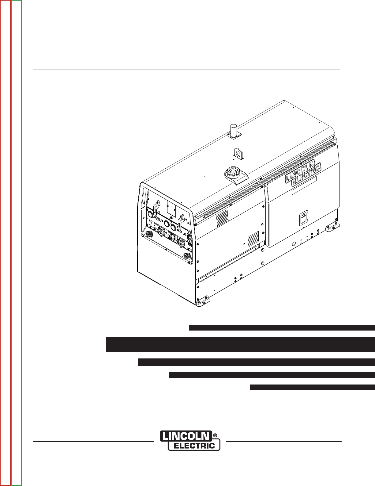
BIG RED®500/600
RETURN TO MAIN MENU
Safety Depends on You
Lincoln arc welding and cutting
equipment is designed and built
with safety in mind. However,
your overall safety can be
increased by proper installation
. . . and thoughtful operation on
your part. DO NOT INSTALL,
OPERATE OR REPAIR THIS
EQUIPMENT WITHOUT READING THIS MANUAL AND THE
SAFETY PRECAUTIONS CONTAINED THROUGHOUT. And,
most importantly, think before you
act and be careful.
SVM212-A
July, 2011
For use with machine code number: 11585, 11599
View Safety Info View Safety Info View Safety Info View Safety Info
Return to Master TOC Return to Master TOC Return to Master TOC Return to Master TOC
Cleveland, Ohio 44117-1199 U.S.A. TEL: 216.481.8100 FAX: 216.486.1751 WEB SITE: www.lincolnelectric.com
SERVICE MANUAL
Copyright © Lincoln Global Inc.
• World's Leader in Welding and Cutting Products •
• Sales and Service through Subsidiaries and Distributors Worldwide •
Page 2
i i
SAFETY
WARNING
CALIFORNIA PROPOSITION 65 WARNINGS
Diesel engine exhaust and some of its constituents
are known to the State of California to cause cancer, birth defects, and other reproductive harm.
The Above For Diesel Engines
ARC WELDING can be hazardous. PROTECT YOURSELF AND OTHERS FROM POSSIBLE SERIOUS INJURY OR DEATH.
KEEP CHILDREN AWAY. PACEMAKER WEARERS SHOULD CONSULT WITH THEIR DOCTOR BEFORE OPERATING.
Read and understand the following safety highlights. For additional safety information, it is strongly recommended that you
purchase a copy of “Safety in Welding & Cutting - ANSI Standard Z49.1” from the American Welding Society, P.O. Box 351040,
Miami, Florida 33135 or CSA Standard W117.2-1974. A Free copy of “Arc Welding Safety” booklet E205 is available from the
Lincoln Electric Company, 22801 St. Clair Avenue, Cleveland, Ohio 44117-1199.
BE SURE THAT ALL INSTALLATION, OPERATION, MAINTENANCE AND REPAIR PROCEDURES ARE
PERFORMED ONLY BY QUALIFIED INDIVIDUALS.
The engine exhaust from this product contains
chemicals known to the State of California to cause
cancer, birth defects, or other reproductive harm.
The Above For Gasoline Engines
FOR ENGINE
powered equipment.
1.a. Turn the engine off before troubleshooting and maintenance
work unless the maintenance work requires it to be running.
____________________________________________________
1.b. Operate engines in open, well-ventilated
areas or vent the engine exhaust fumes
outdoors.
____________________________________________________
1.c. Do not add the fuel near an open flame welding arc or when the engine is running. Stop
the engine and allow it to cool before refueling to prevent spilled fuel from vaporizing on
contact with hot engine parts and igniting. Do
not spill fuel when filling tank. If fuel is spilled,
wipe it up and do not start engine until fumes
have been eliminated.
____________________________________________________
1.d. Keep all equipment safety guards, covers and devices in position and in good repair.Keep hands, hair, clothing and tools
away from V-belts, gears, fans and all other moving parts
when starting, operating or repairing equipment.
____________________________________________________
1.e. In some cases it may be necessary to remove safety
guards to perform required maintenance. Remove
guards only when necessary and replace them when the
maintenance requiring their removal is complete.
Always use the greatest care when working near moving
parts.
___________________________________________________
1.h. To avoid scalding, do not remove the
radiator pressure cap when the engine is
hot.
ELECTRIC AND
MAGNETIC FIELDS
may be dangerous
2.a. Electric current flowing through any conductor causes
localized Electric and Magnetic Fields (EMF). Welding
current creates EMF fields around welding cables and
welding machines
2.b. EMF fields may interfere with some pacemakers, and
welders having a pacemaker should consult their physician
before welding.
2.c. Exposure to EMF fields in welding may have other health
effects which are now not known.
2.d. All welders should use the following procedures in order to
minimize exposure to EMF fields from the welding circuit:
2.d.1.
Route the electrode and work cables together - Secure
them with tape when possible.
2.d.2. Never coil the electrode lead around your body.
1.f. Do not put your hands near the engine fan. Do
not attempt to override the governor or idler by
pushing on the throttle control rods while the
engine is running.
___________________________________________________
1.g. To prevent accidentally starting gasoline engines while
turning the engine or welding generator during maintenance
work, disconnect the spark plug wires, distributor cap or
magneto wire as appropriate.
2.d.3. Do not place your body between the electrode and
work cables. If the electrode cable is on your right
side, the work cable should also be on your right side.
2.d.4. Connect the work cable to the workpiece as close as
possible to the area being welded.
2.d.5. Do not work next to welding power source.
Return to Master TOC Return to Master TOC Return to Master TOC Return to Master TOC
BIG RED®500/600
Page 3
ii ii
SAFETY
ELECTRIC SHOCK can kill.
3.a. The electrode and work (or ground) circuits
are electrically “hot” when the welder is on.
Do not touch these “hot” parts with your bare
skin or wet clothing. Wear dry, hole-free
gloves to insulate hands.
3.b. Insulate yourself from work and ground using dry insulation.
Make certain the insulation is large enough to cover your full
area of physical contact with work and ground.
In addition to the normal safety precautions, if welding
must be performed under electrically hazardous
conditions (in damp locations or while wearing wet
clothing; on metal structures such as floors, gratings or
scaffolds; when in cramped positions such as sitting,
kneeling or lying, if there is a high risk of unavoidable or
accidental contact with the workpiece or ground) use
the following equipment:
• Semiautomatic DC Constant Voltage (Wire) Welder.
• DC Manual (Stick) Welder.
• AC Welder with Reduced Voltage Control.
3.c. In semiautomatic or automatic wire welding, the electrode,
electrode reel, welding head, nozzle or semiautomatic
welding gun are also electrically “hot”.
3.d. Always be sure the work cable makes a good electrical
connection with the metal being welded. The connection
should be as close as possible to the area being welded.
3.e. Ground the work or metal to be welded to a good electrical
(earth) ground.
3.f.
Maintain the electrode holder, work clamp, welding cable and
welding machine in good, safe operating condition. Replace
damaged insulation.
3.g. Never dip the electrode in water for cooling.
3.h. Never simultaneously touch electrically “hot” parts of
electrode holders connected to two welders because voltage
between the two can be the total of the open circuit voltage
of both welders.
3.i. When working above floor level, use a safety belt to protect
yourself from a fall should you get a shock.
3.j. Also see Items 6.c. and 8.
ARC RAYS can burn.
4.a. Use a shield with the proper filter and cover
plates to protect your eyes from sparks and
the rays of the arc when welding or observing
open arc welding. Headshield and filter lens
should conform to ANSI Z87. I standards.
4.b. Use suitable clothing made from durable flame-resistant
material to protect your skin and that of your helpers from
the arc rays.
4.c. Protect other nearby personnel with suitable, non-flammable
screening and/or warn them not to watch the arc nor expose
themselves to the arc rays or to hot spatter or metal.
FUMES AND GASES
can be dangerous.
5.a. Welding may produce fumes and gases
hazardous to health. Avoid breathing these
fumes and gases.When welding, keep
your head out of the fume. Use enough
ventilation and/or exhaust at the arc to keep
fumes and gases away from the breathing zone. When
welding with electrodes which require special
ventilation such as stainless or hard facing (see
instructions on container or MSDS) or on lead or
cadmium plated steel and other metals or coatings
which produce highly toxic fumes, keep exposure as
low as possible and within applicable OSHA PEL and
ACGIH TLV limits using local exhaust or mechanical ventilation. In confined spaces or in some circumstances,
outdoors, a respirator may be required. Additional precautions are also required when welding on galvanized
steel.
5. b. The operation of welding fume control equipment is affected
by various factors including proper use and positioning of the
equipment, maintenance of the equipment and the specific
welding procedure and application involved. Worker exposure level should be checked upon installation and periodically thereafter to be certain it is within applicable OSHA PEL
and ACGIH TLV limits.
5.c.
Do not weld in locations near chlorinated hydrocarbon
coming from degreasing, cleaning or spraying operations.
The heat and rays of the arc can react with solvent vapors
form phosgene, a highly toxic gas, and other irritating products.
vapors
to
5.d. Shielding gases used for arc welding can displace air and
cause injury or death. Always use enough ventilation,
especially in confined areas, to insure breathing air is safe.
5.e. Read and understand the manufacturerʼs instructions for this
equipment and the consumables to be used, including the
material safety data sheet (MSDS) and follow your
employerʼs safety practices. MSDS forms are available from
your welding distributor or from the manufacturer.
5.f. Also see item 1.b.
Return to Master TOC Return to Master TOC Return to Master TOC Return to Master TOC
BIG RED®500/600
Page 4
iii iii
SAFETY
WELDING and CUTTING
SPARKS can cause fire or
explosion.
6.a.
this is not possible, cover them to prevent the welding sparks
from starting a fire. Remember that welding sparks and hot
materials from welding can easily go through small cracks
and openings to adjacent areas. Avoid welding near hydraulic
lines. Have a fire extinguisher readily available.
6.b. Where compressed gases are to be used at the job site,
special precautions should be used to prevent hazardous
situations. Refer to “Safety in Welding and Cutting” (ANSI
Standard Z49.1) and the operating information for the
equipment being used.
6.c. When not welding, make certain no part of the electrode
circuit is touching the work or ground. Accidental contact can
cause overheating and create a fire hazard.
6.d. Do not heat, cut or weld tanks, drums or containers until the
proper steps have been taken to insure that such procedures
will not cause flammable or toxic vapors from substances
inside. They can cause an explosion even
been “cleaned”. For information, purchase “Recommended
Safe Practices for the
Containers and Piping That Have Held Hazardous
Substances”, AWS F4.1 from the American Welding Society
(see address above).
6.e. Vent hollow castings or containers before heating, cutting or
welding. They may explode.
Sparks and spatter are thrown from the welding arc. Wear oil
6.f.
free protective garments such as leather gloves, heavy shirt,
cuffless trousers, high shoes and a cap over your hair. Wear
ear plugs when welding out of position or in confined places.
Always wear safety glasses with side shields when in a
welding area.
6.g. Connect the work cable to the work as close to the welding
area as practical. Work cables connected to the building
framework or other locations away from the welding area
increase the possibility of the welding current passing through
lifting chains, crane cables or other alternate circuits. This can
create fire hazards or overheat lifting chains or cables until
they fail.
6.h. Also see item 1.c.
Remove fire hazards from the welding area.
though
they have
Preparation
for Welding and Cutting of
CYLINDER may explode
if damaged.
7.a. Use only compressed gas cylinders
If
pressure used. All hoses, fittings, etc. should be suitable for
the application and maintained in good condition.
7.b. Always keep cylinders in an upright position securely
chained to an undercarriage or fixed support.
7.c. Cylinders should be located:
• Away from areas where they may be struck or subjected to
physical damage.
• A safe distance from arc welding or cutting operations and
any other source of heat, sparks, or flame.
7.d. Never allow the electrode, electrode holder or any other
electrically “hot” parts to touch a cylinder.
7.e. Keep your head and face away from the cylinder valve outlet
when opening the cylinder valve.
7.f. Valve protection caps should always be in place and hand
tight except when the cylinder is in use or connected for
use.
7.g. Read and follow the instructions on compressed gas
cylinders, associated equipment, and CGA publication P-l,
“Precautions for Safe Handling of Compressed Gases in
Cylinders,” available from the Compressed Gas Association
1235 Jefferson Davis Highway, Arlington, VA 22202.
containing the correct shielding gas for the
process used and properly operating
regulators designed for the gas and
FOR ELECTRICALLY
powered equipment.
8.a. Turn off input power using the disconnect
switch at the fuse box before working on
the equipment.
8.b. Install equipment in accordance with the U.S. National
Electrical Code, all local codes and the manufacturerʼs
recommendations.
8.c. Ground the equipment in accordance with the U.S. National
Electrical Code and the manufacturerʼs recommendations.
6.I. Read and follow NFPA 51B “ Standard for Fire Prevention
During Welding, Cutting and Other Hot Work”, available from
NFPA, 1 Batterymarch Park,PO box 9101, Quincy, Ma
022690-9101.
6.j. Do not use a welding power source for pipe thawing.
Refer to http://www.lincolnelectric.com/safety for additional safety information.
Return to Master TOC Return to Master TOC Return to Master TOC Return to Master TOC
BIG RED®500/600
Page 5

iv iv
SAFETY
PRÉCAUTIONS DE SÛRETÉ
Pour votre propre protection lire et observer toutes les instructions
et les précautions de sûreté specifiques qui parraissent dans ce
manuel aussi bien que les précautions de sûreté générales suivantes:
Sûreté Pour Soudage A LʼArc
1. Protegez-vous contre la secousse électrique:
a. Les circuits à lʼélectrode et à la piéce sont sous tension
quand la machine à souder est en marche. Eviter toujours
tout contact entre les parties sous tension et la peau nue
ou les vétements mouillés. Porter des gants secs et sans
trous pour isoler les mains.
b. Faire trés attention de bien sʼisoler de la masse quand on
soude dans des endroits humides, ou sur un plancher metallique ou des grilles metalliques, principalement dans
les positions assis ou couché pour lesquelles une grande
partie du corps peut être en contact avec la masse.
c. Maintenir le porte-électrode, la pince de masse, le câble de
soudage et la machine à souder en bon et sûr état defonctionnement.
d.Ne jamais plonger le porte-électrode dans lʼeau pour le
refroidir.
e. Ne jamais toucher simultanément les parties sous tension
des porte-électrodes connectés à deux machines à souder
parce que la tension entre les deux pinces peut être le total
de la tension à vide des deux machines.
f. Si on utilise la machine à souder comme une source de
courant pour soudage semi-automatique, ces precautions
pour le porte-électrode sʼapplicuent aussi au pistolet de
soudage.
2. Dans le cas de travail au dessus du niveau du sol, se protéger
contre les chutes dans le cas ou on recoit un choc. Ne jamais
enrouler le câble-électrode autour de nʼimporte quelle partie du
corps.
3. Un coup dʼarc peut être plus sévère quʼun coup de soliel, donc:
6. Eloigner les matériaux inflammables ou les recouvrir afin de
prévenir tout risque dʼincendie dû aux étincelles.
7. Quand on ne soude pas, poser la pince à une endroit isolé de
la masse. Un court-circuit accidental peut provoquer un
échauffement et un risque dʼincendie.
8. Sʼassurer que la masse est connectée le plus prés possible de
la zone de travail quʼil est pratique de le faire. Si on place la
masse sur la charpente de la construction ou dʼautres endroits
éloignés de la zone de travail, on augmente le risque de voir
passer le courant de soudage par les chaines de levage,
câbles de grue, ou autres circuits. Cela peut provoquer des
risques dʼincendie ou dʼechauffement des chaines et des
câbles jusquʼà ce quʼils se rompent.
9. Assurer une ventilation suffisante dans la zone de soudage.
Ceci est particuliérement important pour le soudage de tôles
galvanisées plombées, ou cadmiées ou tout autre métal qui
produit des fumeés toxiques.
10. Ne pas souder en présence de vapeurs de chlore provenant
dʼopérations de dégraissage, nettoyage ou pistolage. La
chaleur ou les rayons de lʼarc peuvent réagir avec les vapeurs
du solvant pour produire du phosgéne (gas fortement toxique)
ou autres produits irritants.
11. Pour obtenir de plus amples renseignements sur la sûreté, voir
le code “Code for safety in welding and cutting” CSA Standard
W 117.2-1974.
PRÉCAUTIONS DE SÛRETÉ POUR
LES MACHINES À SOUDER À
TRANSFORMATEUR ET À
REDRESSEUR
a. Utiliser un bon masque avec un verre filtrant approprié ainsi
quʼun verre blanc afin de se protéger les yeux du rayonnement de lʼarc et des projections quand on soude ou
quand on regarde lʼarc.
b. Porter des vêtements convenables afin de protéger la peau
de soudeur et des aides contre le rayonnement de lʻarc.
c. Protéger lʼautre personnel travaillant à proximité au
soudage à lʼaide dʼécrans appropriés et non-inflammables.
4. Des gouttes de laitier en fusion sont émises de lʼarc de
soudage. Se protéger avec des vêtements de protection libres
de lʼhuile, tels que les gants en cuir, chemise épaisse, pantalons sans revers, et chaussures montantes.
5. Toujours porter des lunettes de sécurité dans la zone de
soudage. Utiliser des lunettes avec écrans lateraux dans les
zones où lʼon pique le laitier.
1. Relier à la terre le chassis du poste conformement au code de
lʼélectricité et aux recommendations du fabricant. Le dispositif
de montage ou la piece à souder doit être branché à une
bonne mise à la terre.
2. Autant que possible, Iʼinstallation et lʼentretien du poste seront
effectués par un électricien qualifié.
3. Avant de faires des travaux à lʼinterieur de poste, la debrancher à lʼinterrupteur à la boite de fusibles.
4. Garder tous les couvercles et dispositifs de sûreté à leur place.
Return to Master TOC Return to Master TOC Return to Master TOC Return to Master TOC
BIG RED®500/600
Page 6

I I
RETURN TO MAIN MENU
- MASTER TABLE OF CONTENTS FOR ALL SECTIONS -
Page
Safety . . . . . . . . . . . . . . . . . . . . . . . . . . . . . . . . . . . . . . . . . . . . . . . . . . . . . . . . . . . . . . . . . . . . . . . . . . .i-vi
Installation . . . . . . . . . . . . . . . . . . . . . . . . . . . . . . . . . . . . . . . . . . . . . . . . . . . . . . . . . . . . . .Section A, AA
Operation . . . . . . . . . . . . . . . . . . . . . . . . . . . . . . . . . . . . . . . . . . . . . . . . . . . . . . . . . . . . . . .Section B, BB
Accessories . . . . . . . . . . . . . . . . . . . . . . . . . . . . . . . . . . . . . . . . . . . . . . . . . . . . . . . . . . . . .Section C, CC
Maintenance . . . . . . . . . . . . . . . . . . . . . . . . . . . . . . . . . . . . . . . . . . . . . . . . . . . . . . . . . . . .Section D, DD
Theory of Operation . . . . . . . . . . . . . . . . . . . . . . . . . . . . . . . . . . . . . . . . . . . . . . . . . . . . . . . . . .Section E
Troubleshooting and Repair . . . . . . . . . . . . . . . . . . . . . . . . . . . . . . . . . . . . . . . . . . . . . . . . . . .Section F
Electrical Diagrams . . . . . . . . . . . . . . . . . . . . . . . . . . . . . . . . . . . . . . . . . . . . . . . . . . . . . . . . . .Section G
Parts Manual . . . . . . . . . . . . . . . . . . . . . . . . . . . . . . . . . . . . . . . . . . . . . . . . . . . . . . . . . . . . .P-619, P-620
BIG RED®500/600
Page 7

II II
NOTES
Return to Master TOC Return to Master TOC Return to Master TOC Return to Master TOC
Return to Section TOC Return to Section TOC Return to Section TOC Return to Section TOC
BIG RED®500/600
Page 8

III III
NOTES
THIS SECTION FOR
BIG RED®500 ONLY.
Return to Master TOC Return to Master TOC Return to Master TOC Return to Master TOC
Return to Section TOC Return to Section TOC Return to Section TOC Return to Section TOC
BIG RED®500/600
Page 9

A-1 A-1
Installation . . . . . . . . . . . . . . . . . . . . . . . . . . . . . . . . . . . . . . . . . . . . . . . . . . . . . . . . . . . . . . . . . . . . . . . . . . . . .A-1
Technical Specifications . . . . . . . . . . . . . . . . . . . . . . . . . . . . . . . . . . . . . . . . . . . . . . . . . . . . . . . . . . . . . . . .A-2
TABLE OF CONTENTS - INSTALLATION SECTION
Safety Precautions . . . . . . . . . . . . . . . . . . . . . . . . . . . . . . . . . . . . . . . . . . . . . . . . . . . . . . . . . . . . . . . . .A-3
Location and Ventilation . . . . . . . . . . . . . . . . . . . . . . . . . . . . . . . . . . . . . . . . . . . . . . . . . . . . . . . . . . . . .A-3
Storing . . . . . . . . . . . . . . . . . . . . . . . . . . . . . . . . . . . . . . . . . . . . . . . . . . . . . . . . . . . . . . . . . . . . . . . . . .A-3
Stacking . . . . . . . . . . . . . . . . . . . . . . . . . . . . . . . . . . . . . . . . . . . . . . . . . . . . . . . . . . . . . . . . . . . . . . . . .A-3
Angle of Operation . . . . . . . . . . . . . . . . . . . . . . . . . . . . . . . . . . . . . . . . . . . . . . . . . . . . . . . . . . . . . . . . .A-3
Lifting . . . . . . . . . . . . . . . . . . . . . . . . . . . . . . . . . . . . . . . . . . . . . . . . . . . . . . . . . . . . . . . . . . . . . . . . . . .A-3
High Altitude Operation . . . . . . . . . . . . . . . . . . . . . . . . . . . . . . . . . . . . . . . . . . . . . . . . . . . . . . . . . . . . .A-3
High Temperature Operation . . . . . . . . . . . . . . . . . . . . . . . . . . . . . . . . . . . . . . . . . . . . . . . . . . . . . . . . .A-3
Towing . . . . . . . . . . . . . . . . . . . . . . . . . . . . . . . . . . . . . . . . . . . . . . . . . . . . . . . . . . . . . . . . . . . . . . . . . .A-4
Vehicle Mounting . . . . . . . . . . . . . . . . . . . . . . . . . . . . . . . . . . . . . . . . . . . . . . . . . . . . . . . . . . . . . . . . . .A-4
Pre-Operation Engine Service . . . . . . . . . . . . . . . . . . . . . . . . . . . . . . . . . . . . . . . . . . . . . . . . . . . . . . . . . . .A-4
Oil . . . . . . . . . . . . . . . . . . . . . . . . . . . . . . . . . . . . . . . . . . . . . . . . . . . . . . . . . . . . . . . . . . . . . . . . . . . . . .A-4
Fuel . . . . . . . . . . . . . . . . . . . . . . . . . . . . . . . . . . . . . . . . . . . . . . . . . . . . . . . . . . . . . . . . . . . . . . . . . . . .A-4
Engine Break-In . . . . . . . . . . . . . . . . . . . . . . . . . . . . . . . . . . . . . . . . . . . . . . . . . . . . . . . . . . . . . . . . . . .A-5
Engine Cooling System . . . . . . . . . . . . . . . . . . . . . . . . . . . . . . . . . . . . . . . . . . . . . . . . . . . . . . . . . . . . .A-5
Battery Connection . . . . . . . . . . . . . . . . . . . . . . . . . . . . . . . . . . . . . . . . . . . . . . . . . . . . . . . . . . . . . . . .A-5
Muffler Outlet Pipe . . . . . . . . . . . . . . . . . . . . . . . . . . . . . . . . . . . . . . . . . . . . . . . . . . . . . . . . . . . . . . . . .A-6
Spark Arrestor . . . . . . . . . . . . . . . . . . . . . . . . . . . . . . . . . . . . . . . . . . . . . . . . . . . . . . . . . . . . . . . . . . . .A-6
Welding Output Cables, Machine Grounding . . . . . . . . . . . . . . . . . . . . . . . . . . . . . . . . . . . . . . . . . . . . . . . .A-6
Auxiliary Power Receptacles, Residual Device Ready, Standby Power Connections . . . . . . . . . . . . . . . . .A-7
Connection of Lincoln Electric Wire Feeders . . . . . . . . . . . . . . . . . . . . . . . . . . . . . . . . . . . . . . . . . . . . . . . .A-8
Return to Master TOC Return to Master TOC Return to Master TOC Return to Master TOC
BIG RED®500/600
Page 10

A-2 A-2
INSTALLATION
TECHNICAL SPECIFICATIONS - BIG RED®500
(K2810-1)
INPUT - DIESEL ENGINE
Make/Model Description Speed (RPM) Displacement Starting Capacities
System
Deutz 3 cylinder Idle 1890 125 cu. in 12VDC battery Fuel
D2011L03i 32HP (24 kw) (2.05L) & Starter (20 US gal)
Diesel Engine @ 1800 RPM Full Load 1800 75.7L
EPA Tier 4i Bore x Stroke
Compliant Oil:
3.89" x 4.13" 6.3 QTS.
(99mm x 105mm) 6.0L
RATED OUTPUT @ 104° F (40° C) - WELDER
Welding Process
DC Constant Current
TIG
Welding Output
Current/Voltage/Duty Cycle
400A / 36V / 100%
450A / 34V / 60%
500A / 30V / 40%
250A / 20V / 100%
Output Range
Amps
65A TO 500A
65A TO 250A
Max. Weld OCV
Voltage @ 1800RPM
90 Volts
75 Volts
RATED OUTPUT @ 104° F (40° C).- GENERATOR
1
AMPS
20
15
15
POWER
2400 Watts
1800 Watts
3600 Watts
OUTLETS
1
1
1
Auxiliary Power
Single Phase 60 Hz AC
VOLTS
120
120
240
RECEPTACLES AND CIRCUIT BREAKERS
RECEPTACLES AUXILIARY POWER CIRCUIT BREAKER OTHER CIRCUIT BREAKERS
1 - 120VAC Duplex NEMA(5-20R) GFCI protected
1 - 120VAC European (IEC-309)-GFCI protected
1 - 240VAC European (IEC-309)
1 - 20 AMP for 120 VAC Duplex (NEMA)
1 - 15 AMP for 120 VAC
1 - 15 AMP for 240 VAC
European (IEC-309)
European (IEC-309)
20AMP for Battery Charging Circuit
PHYSICAL DIMENSIONS
HEIGHT WIDTH DEPTH WEIGHT
(2)
36.87
936.5 mm 718.3 mm 1653.5 mm
1. Output rating in watts is equivalent to volt-amperes at unity power factor. Output voltage is within ± 10% at all loads up to
rated capacity. When welding, available auxiliary power will be reduced.
2. To Top of enclosure, add 9.63”(244.6mm) to top of exhaust pipe.
in. 28.28 in 65.1 in.
1538 lbs. (697 kg.)
Return to Master TOC Return to Master TOC Return to Master TOC Return to Master TOC
Return to Section TOC Return to Section TOC Return to Section TOC Return to Section TOC
BIG RED®500/600
Page 11
A-3 A-3
INSTALLATION
SAFETY PRECAUTION
Read this entire installation section before you start
installation.
WARNING
ELECTRIC SHOCK can kill.
• Do not touch electrically live parts or
electrode with skin or wet clothing.
• Insulate yourself from work and
ground
• Always wear dry insulating gloves.
------------------------------------------------------------------------
ENGINE EXHAUST can kill.
• Use in open, well ventilated areas or
vent exhaust outside.
------------------------------------------------------------------------
MOVING PARTS can injure.
• Do not operate with doors open or
guards off.
• Stop engine before servicing.
• Keep away from moving parts.
------------------------------------------------------------------------
See additional warning information at front
of this operatorʼs manual.
LOCATION AND VENTILATION
The welder should be located to provide an unrestricted flow of clean, cool air to the cooling air inlets and to
avoid restricting the cooling air outlets. Also, locate the
welder so that the engine exhaust fumes are properly
vented to an outside area.
STORING
1. Store the machine in a cool, dry place when it is
not in use. Protect it from dust and dirt. Keep it
where it canʼt be accidentally damaged from construction activities, moving vehicles, and other
hazards.
2. Drain the engine oil and refill with fresh 10W30 oil.
Run the engine for about five minutes to circulate
oil to all the parts. See the MAINTENANCE sec-
tion of this manual for details on changing oil.
3. Remove the battery, recharge it, and adjust the
electrolyte level. Store the battery in a dry, dark
place.
ANGLE OF OPERATION
To achieve optimum engine performance the BIG
®
500 should be run in a level position. The max-
RED
imum angle of operation for the Deutz engine is 20
degrees in direction of control panel angled up and 30
degrees for left, right and control panel angled down. If
the engine is to be operated at an angle, provisions
must be made for checking and maintaining the oil
level at the normal (FULL) oil capacity in the
crankcase. When operating the welder at an angle, the
effective fuel capacity will be slightly less than the
amount specified.
LIFTING
The BIG RED®500 weighs approximately 1653lbs.
(750kg.) with a full tank of fuel 1538lbs.(697kg) less
fuel. A lift bail is mounted to the machine and should
always be used when lifting the machine.
WARNING
• Lift only with equipment of adequate lifting capacity.
• Be sure machine is stable when lifting.
• Do not lift this machine using lift
bail if it is equipped with a heavy
accessory such as trailer or gas
cylinder.
FALLING • Do not lift machine if lift bail is
EQUIPMENT can damaged.
cause injury. • Do not operate machine while
suspended from lift bail.
--------------------------------------------------------------------------------
HIGH ALTITUDE OPERATION
At higher altitudes, output derating may be necessary.
For maximum rating, derate the welder output 5% for
every 300 meters (984 ft.) above 1500 meters (4920
ft.). For output of 400A and below, derate the welder
output 5% for every 300 meters (984 ft.) above 2100
meters (6888 ft.).
Contact a Deutz Service Representative for any
engine adjustments that may be required.
HIGH TEMPERATURE OPERATION
WELDER OUTPUT RATINGS AT
STACKING
AMPS DUTY CYCLE VOLTS TEMPERATURE
BIG RED®500 machines cannot be stacked.
Return to Master TOC Return to Master TOC Return to Master TOC Return to Master TOC
Return to Section TOC Return to Section TOC Return to Section TOC Return to Section TOC
BIG RED®500/600
350 DC 30% 34 55
400 DC 30% 36 50
450 DC 30% 34 45
TEMPERATURES ABOVE 40°C
°
C
°
C
°
C
Page 12
A-4 A-4
INSTALLATION
TOWING
Use a recommended trailer for use with this equipment
for road, in-plant and yard towing by a vehicle(1). If the
user adapts a non-Lincoln trailer, he must assume
responsibility that the method of attachment and usage
does not result in a safety hazard or damage the welding equipment. Some of the factors to be considered
are as follows:
1. Design capacity of trailer vs. weight of Lincoln equipment and likely additional attachments.
2. Proper support of, and attachment to, the base of
the welding equipment so there will be no undue
stress to the framework.
3. Proper placement of the equipment on the trailer to
insure stability side to side and front to back when
being moved and when standing by itself while
being operated or serviced.
4. Typical conditions of use, i.e., travel speed; roughness of surface on which the trailer will be operated;
environmental conditions; like maintenance.
5. Conformance with federal, state and local laws.
(1) Consult applicable federal, state and local laws regarding spe-
cific requirements for use on public highways.
(1)
VEHICLE MOUNTING
WARNING
Improperly mounted concentrated loads may
cause unstable vehicle handling and tires or other
components to fail.
• Only transport this Equipment on serviceable
vehicles which are rated and designed for such
loads.
• Distribute, balance and secure loads so vehicle
is stable under conditions of use.
• Do not exceed maximum rated loads for components such as suspension, axles and tires.
• Mount equipment base to metal bed or frame of
vehicle.
• Follow vehicle manufactureʼs instructions.
------------------------------------------------------------------------
PRE-OPERATION ENGINE SERVICE
READ the engine operating and maintenance instructions supplied with this machine.
WARNING
Stop engine while fueling.
• Do not smoke when fueling.
• Keep sparks and flame away from
tank.
• Do not leave unattended while
fueling.
DIESEL FUEL
can cause fire.
• Wipe up spilled fuel and allow
fumes to clear before starting
engine.
• Do not overfill tank, fuel expan-
sion may cause overflow.
DIESEL FUEL ONLY
USE DIESEL FUEL ONLY - Low Sulphur fuel or ultra
low sulphur fuel in USA and CANADA only.
-----------------------------------------------------------------------------------------
OIL
The BIG RED®500 is shipped with the engine
crankcase filled with high quality SAE 10W-30 oil (API
class CD or better). Check the oil level before starting
the engine. If it is not up to the full mark on the dip stick,
add oil as required. Check the oil level every four hours
of running time during the first 35 running hours. Refer
to the engine Operatorʼs Manual for specific oil recommendations and break-in information. The oil change
interval is dependent on the quality of the oil and the
operating environment. Refer to the engine Operatorʼs
Manual for the proper service and maintenance intervals. The machine is equipped with an oil drain valve.
FUEL
WARNING
USE DIESEL FUEL ONLY - Low Sulphur fuel or ultra
low sulphur fuel in USA and CANADA only.
• Fill the fuel tank with clean, fresh fuel. The
capacity of the tank is 20 gals. (75.7 ltrs). When
the fuel gauge reads empty the tank contains
approximately 2 gals. (7.6ltrs.) of reserve fuel.
WARNING
NOTE: A fuel shut off valve is located to the left of
the fuel lift pump and should be in the
closed position when the welder is not used
for extended periods of time.
------------------------------------------------------------------------
Return to Master TOC Return to Master TOC Return to Master TOC Return to Master TOC
Return to Section TOC Return to Section TOC Return to Section TOC Return to Section TOC
BIG RED®500/600
Page 13
A-5 A-5
INSTALLATION
ENGINE BREAK-IN
Lincoln Electric selects high quality, heavy-duty industrial engines for the portable welding machines we
offer. While it is normal to see a small amount of
crankcase oil consumption during initial operation,
excessive oil use, wetstacking (oil or tar like substance
at the exhaust port), or excessive smoke is not normal.
Larger machines with a capacity of 350 amperes and
higher, which are operated at low or no-load conditions
for extended periods of time are especially susceptible
to the conditions described above. To accomplish successful engine break-in, most diesel-powered equipment needs only to be run at a reasonably heavy load
within the rating of the welder for some period of time
during the engineʼs early life. However, if the welder is
subjected to extensive light loading, occasional moderate to heavy loading of the engine may sometimes be
necessary. Caution must be observed in correctly
loading a diesel/generator unit.
1. Connect the welder output studs to a suitable resistive load bank. Note that any
attempt to short the output studs by connecting the welding leads together, direct
shorting of the output studs, or connecting
the output leads to a length of steel will
result in catastrophic damage to the generator and voids the warranty.
2. Set the welder controls for an output current and voltage within the welder rating
and duty cycle. Note that any attempt to
exceed the welder rating or duty cycle for
any period of time will result in catastrophic
damage to the generator and voids the
warranty.
3. Periodically shut off the engine and check
the crankcase oil level.
ENGINE COOLING SYSTEM
The Deutz engine is air cooled by a belt driven axial
blower. The oil cooler and engine cooling fins should
be blown out with compressed air or steam to maintain
proper cooling (See the engine Owners Manual for
procedures and frequency).
BATTERY CONNECTION
WARNING
GASES FROM BATTERY can explode.
• Keep sparks, flame and cigarettes
away from battery.
To prevent EXPLOSION when:
• INSTALLING A NEW BATTERY — disconnect negative cable from old battery first and connect to
new battery last.
• CONNECTING A BATTERY CHARGER — remove
battery from welder by disconnecting negative
cable first, then positive cable and battery clamp.
When reinstalling, connect negative cable last.
Keep well ventilated.
• USING A BOOSTER — connect positive lead to
battery first then connect negative lead to negative battery lead at engine foot.
BATTERY ACID can burn eyes and skin.
• Wear gloves and eye protection and be
careful when working near battery.
• Follow instructions printed on battery.
IMPORTANT: To prevent ELECTRICAL DAMAGE
WHEN:
a) Installing new batteries.
b) Using a booster.
Use correct polarity — Negative Ground.
------------------------------------------------------------------------
The BIG RED
cable disconnected. Before you operate the machine,
make sure the Engine Switch is in the OFF position
and attach the disconnected cable securely to the negative (-) battery terminal.
Remove the insulating cap from the negative battery
terminal. Replace and tighten negative battery cable
terminal.
NOTE: This machine is furnished with a wet charged
®
500 is shipped with the negative battery
battery; if unused for several months, the battery may require a booster charge. Be sure to
use the correct polarity when charging the battery.
Return to Master TOC Return to Master TOC Return to Master TOC Return to Master TOC
Return to Section TOC Return to Section TOC Return to Section TOC Return to Section TOC
BIG RED®500/600
Page 14

A-6 A-6
INSTALLATION
MUFFLER OUTLET PIPE
Remove the plastic plug covering the muffler outlet
tube. Using the clamp provided secure the outlet pipe
to the outlet tube with the pipe positioned such that it
will direct the exhaust in the desired position
.
SPARK ARRESTOR
Some federal, state or local laws may require that
petrol or diesel engines be equipped with exhaust
spark arrestors when they are operated in certain locations where unarrested sparks may present a fire hazard. The standard muffler included with this welder
does not qualify as a spark arrestor. When required by
local regulations, a suitable spark arrestor, must be
installed and properly maintained.
CAUTION
An incorrect arrestor may lead to damage to the
engine or adversely affect performance.
------------------------------------------------------------------------
WELDING OUTPUT CABLES
With the engine off, connect the electrode and work
cables to the output studs. The welding process dictates the polarity of the electrode cable. These connections should be checked periodically and tightened
if necessary.
Listed in Table A.1 are copper cable sizes recommended for the rated current and duty cycle. Lengths
stipulated are the distance from the welder to work and
back to the welder again. Cable sizes are increased for
greater lengths primarily for the purpose of minimizing
cable voltage drop.
Table A.1 Combined Length of Electrode and Work
Cables.
MACHINE GROUNDING
Because this portable engine driven welder creates its
own power, it is not necessary to connect its frame to
an earth ground, unless the machine is connected to
premises wiring (home, shop, etc.).
To prevent dangerous electric shock, other equipment
powered by this engine driven welder must:
a) be grounded to the frame of the welder using a
grounding type plug,
or
b) be double insulated.
When this welder is mounted on a truck or trailer, its
frame must be securely connected to the metal frame
of the vehicle. When this engine driven welder is connected to premises wiring such as that in a home or
shop, its frame must be connected to the system earth
ground. See further connection instructions in the section entitled Standby Power Connections as well as
the article on grounding in the latest National Electrical
Code and the local codes.
In general, if the machine is to be grounded, it should
be connected with a #8 or larger copper wire to a solid
earth ground such as a metal ground stake going into
the ground for at least 10 Feet or to the metal framework of a building which has been effectively grounded. The National Electric Code lists a number of alternate means of grounding electrical equipment. A
machine grounding stud marked with the symbol is
provided on the front of the welder.
TOTAL COMBINED LENGTH OF ELECTRODE
AMPS Up to 150 ft. 150-200 ft. 200-250 ft.
@100% (Up to 45m) (45-60m) (60-75m)
Duty Cycle
400 3/0 AWG 3/0 AWG 4/0 AWG
95mm
Return to Master TOC Return to Master TOC Return to Master TOC Return to Master TOC
Return to Section TOC Return to Section TOC Return to Section TOC Return to Section TOC
AND WORK CABLES
2
95mm
2
120mm
2
BIG RED®500/600
Page 15

A-7 A-7
INSTALLATION
AUXILIARY POWER RECEPTACLES
The auxiliary power of the BIG RED®500 consists of
Single Phase 60Hz Power. Output Voltage is within +/10% at loads up to rated capacity.
One 120VAC NEMA (5-20R) 20 amp duplex receptacle
is protected by a 20 amp circuit breaker that provides
2400 watts Continuous power. Maximum current is 20
amps total.
One 120VAC European (IEC-309) 16 amp receptacle
is protected by a 15 amp circuit breaker that provides
1800 watts Continuous power. Maximum current is 15
amps.
One 240VAC European (IEC-309) 16 amp receptacle
is protected by a 15 amp 2-pole circuit breaker that
provides 3600 watts Continuous power. The 2-pole circuit breaker disconnects both hot leads at the same
time. Maximum current is 15 amps.
120 VOLT RECEPTACLES
RESIDUAL CURRENT DEVICE READY
The BIG RED®500 is configured to allow for the addition of a Residual Current Device (RCD) to protect the
240V Single Phase Receptacle. The auxiliary power
area on the front panel of the BIG RED
hole sized and shaped to accept a typical 2-pole (RCD)
along with a protective rubber boot. A cover plate with
a label “RCD READY” covers the hole and secures a
mounting bracket on the backside of the panel.
NOTE: The (RCD) should be rated for at least 15
amps.
There are many suppliers of RCDʼs. One example is
Allen Bradley, part number 1492-RCD2A40.
The protective boot can be obtained from:
APM-Hexseal, part number HE-1035
See Section F Diagrams of the Operatorʼs Manual for
this machine for instructions on installing an RCD and
protective rubber boot.
®
500 has a
A GFCI module protects, the two 120V Auxiliary Power
receptacles. A GFCI (Ground Fault Circuit Interrupter)
electrical receptacle is a device to protect against elec-
tric shock should a piece of defective equipment connected to it develop a ground fault. If this situation
should occur, the GFCI module will trip, removing voltage from the output of the receptacle. If a GFCI module is tripped see the MAINTENANCE section for
detailed information on testing and resetting it. A GFCI
module should be properly tested at least once every
month.
The 120 V auxiliary power receptacles should only be
used with three wire grounded type plugs or approved
double insulated tools with two wire plugs. The current
rating of any plug used with the system must be at
least equal to the current capacity of the associated
receptacle.
STANDBY POWER CONNECTIONS
The BIG RED®500 is suitable for temporary, standby
or emergency power using the engine manufacturerʼs
recommended maintenance schedule.
The BIG RED®500 can be permanently installed as a
standby power unit for 240 VAC(60Hz). Connections
must be made by a licensed electrician who can determine how the 120/240 VAC power can be adapted to
the particular installation and comply with all applicable
electrical codes.
Take necessary steps to assure load is limited to the
capacity of the BIG RED
®
500
WARNING
• Only a licensed, certified, trained electrician
should install the machine to a premises or residential electrical system. Be certain that:
• The installation complies with the National
Electrical Code and all other applicable electrical
codes.
• The premises is isolated and no feedback into the
utility system can occur. Certain state and local
laws require the premises to be isolated before
the generator is linked to the premises. Check
your state and local requirements.
------------------------------------------------------------------------
Return to Master TOC Return to Master TOC Return to Master TOC Return to Master TOC
Return to Section TOC Return to Section TOC Return to Section TOC Return to Section TOC
BIG RED®500/600
Page 16
A-8 A-8
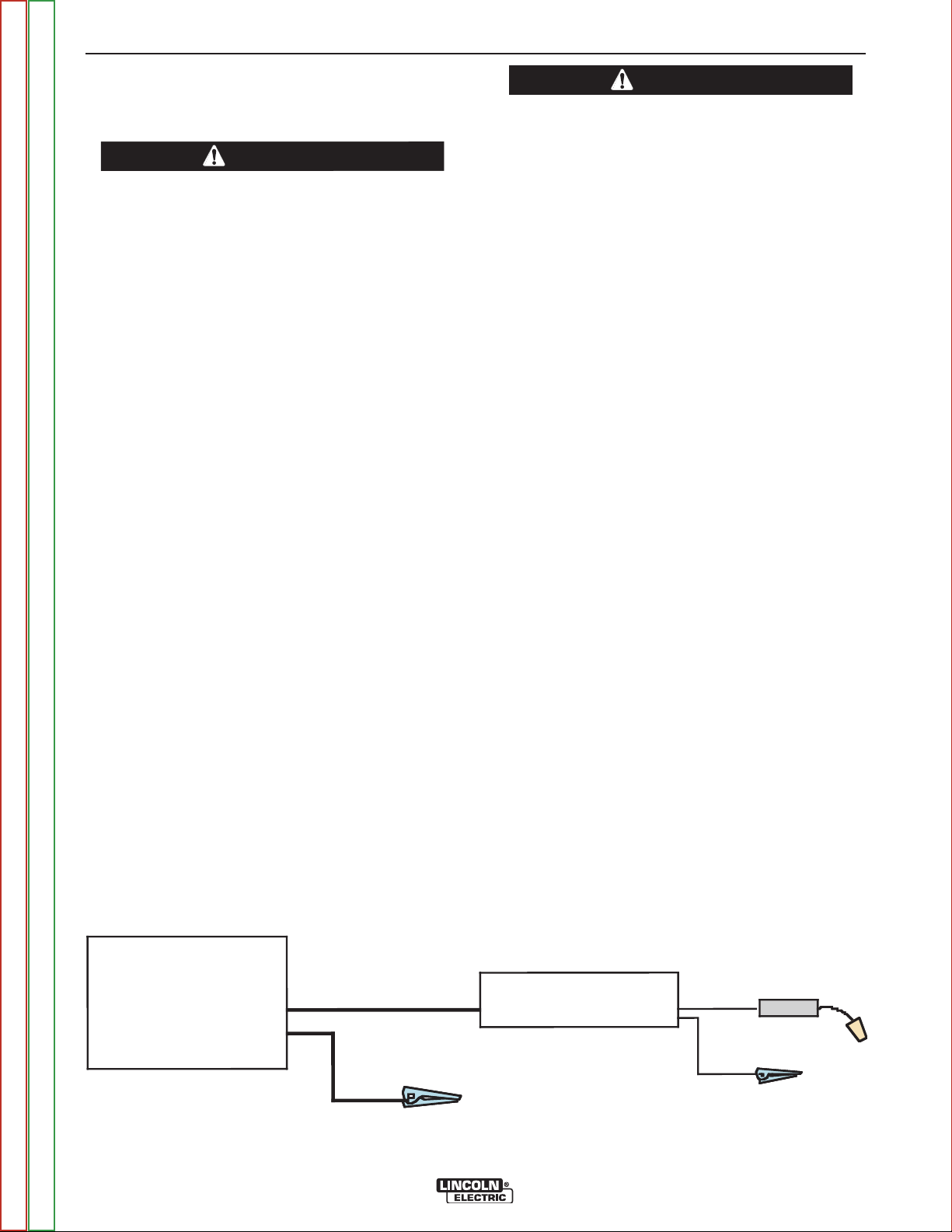
BIG RED™ 500
Wor k
Electrode
Wo rk c lip
LN-15™ ACROSS THE ARC
LN-25™, LN-25™ PRO
NOTES
CONNECTION OF LINCOLN ELECTRIC
WIRE FEEDERS
WARNING
Shut off Welder before making any electrical connections.
------------------------------------------------------------------------
®
The LN-15
Across-the-Arc model, LN-25
out an internal contactor, and LN-25
®
used with the BIG RED
500.
1. Shut the welder off.
2. For electrode Positive, connect the electrode cable
from the wire feeder to the “+” terminal of the welder
and work cable to the “-” terminal of the welder. For
electrode Negative, connect the electrode cable
from the wire feeder to the “-” terminal of the welder
and work cable to the “+” terminal of the welder.
3. Set the CV/CC mode of the wire feeder to CC.
(Refer to wire feeder operator manual for details on
setting the wire feeder in the CC mode and for setting welding parameters).
®
with or with-
®
PRO may be
WARNING
®
If you are using an LN-25
tactor, the electrode will be energized when the
®
BIG RED
500 is started.
------------------------------------------------------------------------
The Wire Feeder sensor has full OCV potential
between spring clip and work return. Turn machine
off when attaching spring clip.
------------------------------------------------------------------------
Lincoln Electric does NOT recommend constant
current semiautomatic welding for applications
which need to meet specified weld metal chemical
or mechanical property requirements or weld quality requirements.
------------------------------------------------------------------------
without an internal con-
4. Attach the single lead from the front of the wire feeder to work using the spring clip at the end of the lead.
This is a sense lead to supply current to the wire
feeder motor; it does not carry welding current.
5. When the gun trigger is closed, the current sensing
circuit will cause the wire to begin to feed and the
welding process is started.
®
NOTE: The LN-25
(K444-1) Remote Control Module
(K431) and Remote Cable (K432) cannot be
®
used with the BIG RED
500. See the appro-
priate connection diagram in Section F of the
Operatorʼs manual.
FIGURE A-1
Return to Master TOC Return to Master TOC Return to Master TOC Return to Master TOC
Return to Section TOC Return to Section TOC Return to Section TOC Return to Section TOC
BIG RED®500/600
Page 17

B-1 B-1
Operation . . . . . . . . . . . . . . . . . . . . . . . . . . . . . . . . . . . . . . . . . . . . . . . . . . . . . . . . . . . . . . . . . . . . . . . . . . . . . .B-1
Safety Instructions . . . . . . . . . . . . . . . . . . . . . . . . . . . . . . . . . . . . . . . . . . . . . . . . . . . . . . . . . . . . . . . . . . . .B-2
General Description . . . . . . . . . . . . . . . . . . . . . . . . . . . . . . . . . . . . . . . . . . . . . . . . . . . . . . . . . . . . . . . . . . .B-2
Recommended Applications . . . . . . . . . . . . . . . . . . . . . . . . . . . . . . . . . . . . . . . . . . . . . . . . . . . . . . . . . . . . .B-2
Controls and Settings . . . . . . . . . . . . . . . . . . . . . . . . . . . . . . . . . . . . . . . . . . . . . . . . . . . . . . . . . . . . . . . . . .B-3
Welder Controls . . . . . . . . . . . . . . . . . . . . . . . . . . . . . . . . . . . . . . . . . . . . . . . . . . . . . . . . . . . . . . . . . . .B-3
Engine Controls . . . . . . . . . . . . . . . . . . . . . . . . . . . . . . . . . . . . . . . . . . . . . . . . . . . . . . . . . . . . . . . . . . .B-4
Auxiliary Power . . . . . . . . . . . . . . . . . . . . . . . . . . . . . . . . . . . . . . . . . . . . . . . . . . . . . . . . . . . . . . . . . . .B-4
Engine Operation . . . . . . . . . . . . . . . . . . . . . . . . . . . . . . . . . . . . . . . . . . . . . . . . . . . . . . . . . . . . . . . . . . . . .B-5
TABLE OF CONTENTS - OPERATION SECTION
Starting the Engine . . . . . . . . . . . . . . . . . . . . . . . . . . . . . . . . . . . . . . . . . . . . . . . . . . . . . . . . . . . . . . . .B-5
Cold Weather Starting and Operation . . . . . . . . . . . . . . . . . . . . . . . . . . . . . . . . . . . . . . . . . . . . . . . . . .B-5
Stoping the Engine . . . . . . . . . . . . . . . . . . . . . . . . . . . . . . . . . . . . . . . . . . . . . . . . . . . . . . . . . . . . . . . .B-5
Welding Operation . . . . . . . . . . . . . . . . . . . . . . . . . . . . . . . . . . . . . . . . . . . . . . . . . . . . . . . . . . . . . . . . . . . .B-6
Stick . . . . . . . . . . . . . . . . . . . . . . . . . . . . . . . . . . . . . . . . . . . . . . . . . . . . . . . . . . . . . . . . . . . . . . . . . . . .B-6
Arc Gouging . . . . . . . . . . . . . . . . . . . . . . . . . . . . . . . . . . . . . . . . . . . . . . . . . . . . . . . . . . . . . . . . . . . . . .B-6
TIG Welding . . . . . . . . . . . . . . . . . . . . . . . . . . . . . . . . . . . . . . . . . . . . . . . . . . . . . . . . . . . . . . . . . . . . . .B-7
Constant Current Operation with Lincoln Wire Feeder . . . . . . . . . . . . . . . . . . . . . . . . . . . . . . . . . . . . .B-8
Auxiliary Power . . . . . . . . . . . . . . . . . . . . . . . . . . . . . . . . . . . . . . . . . . . . . . . . . . . . . . . . . . . . . . . . . . . . . . .B-9
Simultaneous Welding and Power Loads . . . . . . . . . . . . . . . . . . . . . . . . . . . . . . . . . . . . . . . . . . . . . . .B-9
Return to Master TOC Return to Master TOC Return to Master TOC Return to Master TOC
BIG RED®500/600
Page 18

B-2 B-2
OPERATION
SAFETY INSTRUCTIONS
Read and understand this entire section before
operating your BIG RED
®
500.
WARNING
Do not attempt to use this equipment until you
have thoroughly read all operating and maintenance manuals supplied with your machine. They
include important safety precautions, detailed
engine starting, operating and maintenance
instructions and parts lists.
ELECTRIC SHOCK can kill.
• Do not touch electrically live parts
such as output terminals or internal
wiring.
• Insulate yourself from the work and
ground.
• Always wear dry insulating gloves.
------------------------------------------------------------------------
ENGINE EXHAUST can kill.
• Use in open, well ventilated areas or
vent exhaust outside
• Do not stack anything near the engine.
------------------------------------------------------------------------
MOVING PARTS can injure.
• Do not operate with doors open or
guards off.
• Stop engine before servicing.
• Keep away from moving parts
------------------------------------------------------------------------
Only qualified personnel should operate this
equipment.
------------------------------------------------------------------------
ADDITIONAL SAFETY PRECAUTIONS
GENERAL DESCRIPTION
The BIG RED®500 is a diesel engine driven welder,
offering reliable DC arc welding performance, with outstanding arc characteristics for all welding applications.
The BIG RED
diesel engine driven 500 amp DC arc welder and 3.6
KW AC power generator. This powerful generator can
be used to provide electricity for lights, power tools,
etc.
The BIG RED®500 delivers ideal DC arc characteristic
for each welding process. Stick electrode welding,
Scratch-Start TIG, or carbon arc gouging, to make the
BIG RED®500 the ideal all purpose engine driven
welder for on-site work.
The BIG RED®500 has “no PC Boards” and “no electronics”.
The BIG RED®500 is service friendly with a minimal
number of major parts, simplifying in field servicing of
the BIG RED®500. The generator is a dual stator and
rotor design with two sealed bearings for maintenance
free service. The rotors are copper wound design with
two slip rings and brushes. The stators are wound
entirely with heavy gauge copper wire and insulated
with NEMA class F insulation material. The stator is
then impregnated with three layers of high quality varnish. After the stator is assembled using tie bars, the
entire assembly Is covered with an environmentally
protective coating . These measures insure troublefree operation in the harshest environments.
®
500 is both a rugged three cylinder,
RECOMMENDED APPLICATIONS
WELDER
The BIG RED
ing output for stick (SMAW) and TIG (GTAW) welding
(scratch start). In addition the Big Red can be used for
Arc Gouging with carbons up to 8.0 mm (5/16”) diameter.
®
500 provides constant current DC weld-
Always operate the welder with the hinged door
closed and the side panels in place as these provide maximum protection from moving parts and
insure proper cooling air flow.
------------------------------------------------------------------------
Return to Master TOC Return to Master TOC Return to Master TOC Return to Master TOC
Return to Section TOC Return to Section TOC Return to Section TOC Return to Section TOC
BIG RED®500/600
The BIG RED®500 is not recommended for pipe
thawing.
GENERATOR
The BIG RED®500 provides smooth output for auxiliary power and emergency standby power. The auxiliary power is independent of the welding power and
thus not effected by the weld control settings. Full
power is available provided welding output is below
200 amps. Above 200 amps refer to the Simultaneous
Welding and Auxiliary Power chart in the operation
section of this manual.
Page 19
B-3 B-3
CONTROLS AND SETTINGS
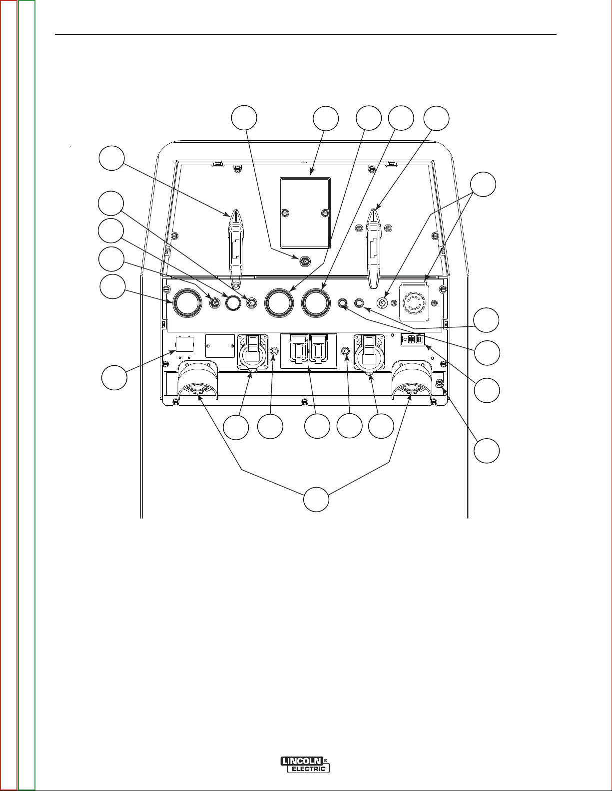
All welder and engine controls are located on the case front panel. Refer to Figure B.1 and the explanations that
follow.
Figure B.1 Case Front Panel Controls
OPERATION
1
9
8
7
6
14
3
4
10
11
2
5
13
12
20
15
WELDING CONTROLS (Items 1-5)
1. OUTPUT RANGE SELECTOR SWITCH
A 5 position switch that provides 5 overlapping output current settings:
• 65 - 115
• 105 - 220
• 150 - 330
• 200 - Maximum
NOTE: Do not switch while welding
16
17
18
19
22
21
2. OUTPUT CONTROL
Provides fine adjustment of the current and open
circuit voltage from minimum to maximum within
each Range.
“1ʼʼ is minimum and “10” is maximum.
3. WELD MODE SELECTOR SWITCH
Provides selection of either Stick / Arc Gouging
Mode or TIG Mode.
4. VOLT/AMP METERS (optional)
Optional analog volt and amp meter kit available for
easy installation into front panel.
Return to Master TOC Return to Master TOC Return to Master TOC Return to Master TOC
Return to Section TOC Return to Section TOC Return to Section TOC Return to Section TOC
BIG RED®500/600
(See Accessory Section For “K” number)
Page 20

B-4 B-4
5. LOCAL / REMOTE CONTROL SWITCH and
REMOTE RECEPTACLE
The toggle switch provides the option of controlling
the welding output at the control panel or remotely.
For control at the control panel set the switch in the
"LOCAL" position. For remote control set the switch
in the "REMOTE" position. The receptacle is for
attaching an optional remote control equipment.
(See Accessory Section For “K” number)
ENGINE CONTROLS (Items 6 Through to
13)
OPERATION
11. OIL PRESSURE GAUGE
An indicator of engine oil pressure.
12. ENGINE PROTECTION
A warning indicator light for high oil temperature or
low oil pressure. The light remains off with proper
oil temperature and proper oil pressure. If a fault is
detected the light will turn on and the engine protection system will stop the engine. The light will
remain on when the engine has been shut down.
In order to try and re-start the engine the engine
protection system must be reset by returning the
RUN-STOP switch to the STOP position.
6. ENGINE HOUR METER / FUEL GAUGE
Combination hour meter fuel level gauge. The hour
meter displays the total time that the engine has
been running. This meter is a useful indicator for
scheduling preventive maintenance. The fuel gauge
displays the level of diesel fuel in the fuel tank. The
operator must watch the fuel level closely to prevent
running out of fuel and possibly having to bleed the
system.
7. RUN STOP SWITCH
The RUN position energizes the hold coil of the fuel
solenoid, hour meter, and rotor flashing circuit. The
STOP position stops the engine.
NOTE: Do not leave switch in RUN position when
the engine is not running. In the RUN position the battery will be discharged.
8. START PUSH BUTTON
Energizes the starter motor to crank the engine.
With the RUN / STOP switch in the RUN position,
push and hold the Start button to crank the engine;
release as the engine starts. Do not press while
engine is running as this can cause damage to the
ring gear and/or starter motor.
9. CIRCUIT BREAKER
The battery circuit breaker protects the engine circuitry that powers the three gauges, fuel/hours, temperature and pressure. It also protects the engine
shutdown relay, timer delay relay, hot start relay
hold solenoid, and flashing circuitry. When the circuit breaker opens because of a fault, the engine
will crank but will not start.
10. OIL TEMPERATURE GAUGE
An indicator of engine oil temperature.
NOTE: The light remains off when the RUN-STOP
switch is in the RUN position prior to starting the engine. However if the engine is not
started within 60 seconds the light will come
on. When this happens the RUN-STOP
switch must be returned to the STOP position to reset the engine protection system
and light.
13. BATTERY CHARGING LIGHT
An indicator light for low/no battery charging. The
light is off when the battery charging system is
functioning normally. If light turns on, the alternator
or the voltage regulator may not be operating correctly or the cooling blower belt may be broken.
The light will remain on when the engine is
stopped and the RUN / STOP switch is in the RUN
position.
AUXILIARY POWER (14-22)
14. CIRCUIT BREAKER
2-pole 15A rated. Provides overload protection for
the 240VAC European (IEC-309) receptacle.
15. 240 VAC RECEPTACLE
European (IEC-309) receptacle rated up to 16
amps and is IP44 rated.
NOTE: A space is provided on the panel for adding a
2-pole Residual Current Device (RCD) to protect the 240V receptacle. See Section F of
Operatorʼs Manual for instructions on installing
an RCD.
16. CIRCUIT BREAKER
Single-pole 20A rated. Provides overload protection for the 120VAC (5-20R) NEMA Duplex
Receptacle.
Return to Master TOC Return to Master TOC Return to Master TOC Return to Master TOC
Return to Section TOC Return to Section TOC Return to Section TOC Return to Section TOC
BIG RED®500/600
Page 21

B-5 B-5
17. 120 VAC DUPLEX RECEPTACLE
Single-pole 20A rated. Provides overload protection for the 120VAC (5-20R) NEMA Duplex
OPERATION
8. Allow the engine to warm up for several minutes
before applying a load. Allow a longer warm up time
in cold weather.
Receptacle.
18. CIRCUIT BREAKERS
Single pole 15A rated. Provides overload protection for the 120VAC European (IEC-309) receptacle.
19. 120 VAC RECEPTACLE
European (IEC-309) receptacle rated up to 16
amps and is IP44 rated. Receptacle is GFCI pro-
COLD WEATHER STARTING
With a fully charged battery and the proper weight
oil, the engine should start satisfactorily even down
to about -15°C(5°F). If the engine must be frequently started below -15°C(5°F), it may be desirable to
install additional starting aids. The use of No. 1D
diesel fuel is recommended in place of No. 2D at
temperatures below -5°C(23° F).
tected.
STOPPING THE ENGINE
20. GFCI (Ground Fault Circuit Interrupter) Module
Protects both 120VAC Auxiliary Power receptacles.
If a GFCI Module is tripped, See the MAINTE-
NANCE section for detailed information on testing
and resetting the GFCI Module.
Switch the RUN/STOP switch to “STOP”. This turns
off the voltage supplied to the shutdown solenoid. A
backup shutdown can be accomplished by shutting
off the fuel valve located on the fuel line.
NOTE: Also put Run/Stop switch in “Stop” position
when engine is not running - battery will be discharged otherwise.
21. WELD OUTPUT TERMINALS + AND -
Covered terminals that provide welding connection
points for the electrode and work cables.
22. GROUND STUD
Protects both 120VAC Auxiliary Power receptacles.
ENGINE OPERATION
STARTING THE ENGINE
1. Open the engine compartment door and check that
the fuel shut off valve located screwed into the fuel
filter housing is in the open position (lever to be in
line with the hose).
2. Check for proper oil level. Close engine compartment door.
3. Remove all plugs connected to the AC power receptacles.
4. Set the RUN/STOP switch to “RUN”. Observe that
the battery charging light is on and fuel is in the fuel
tank (see fuel gauge).
5. Within 30 seconds, press and hold the engine
START button until the engine starts.
6. Release the engine START button when the engine
starts.
7. Check that the engine protection and battery charging lights are off. The engine protection light is on
after starting, the engine will shutdown in a few seconds. Investigate any indicated problem.
TABLE B.1
TYPICAL
High Idle - No Load
1890 R.P.M.
DC, CC Weld Output
400A/36V/100%
DC, CC Weld Output
500A/30V/40%
Auxiliary Power
3.6 Kw
BIG RED®500
Deutz D2011L03i Engine
32HP (24Kw) @ 1800 RPM
FUEL CONSUMPTION
2.1 liters/hr
(.56 gal/hr)
5.6 liters/hr
(1.49 gal/hr)
3.6 liters/hr
(.97 gal/hr)
2.6 liters/hr
(.69 gal/hr)
Running Time for
75.7 L (20 Gal.)
35.6 hrs
13.4 hrs
20.7 hrs
28.9 hrs
NOTE: This data is for reference only. Fuel consump-
tion is approximate and can be influenced by
many factors, including engine maintenance,
environmental conditions and fuel quality.
Return to Master TOC Return to Master TOC Return to Master TOC Return to Master TOC
Return to Section TOC Return to Section TOC Return to Section TOC Return to Section TOC
BIG RED®500/600
Page 22
B-6 B-6
OPERATION
WELDER OPERATION
DUTY CYCLE
Duty Cycle is the percentage of time the load is
being applied in a 10 minute period. For example a
60% duty cycle, represents 6 minutes of load and 4
minutes of no load in a 10 minute period.
ELECTRODE INFORMATION
The BIG RED
cal up, and overhead welding with all types of DC
stick electrodes.
For any electrode the procedures should be kept
within the rating of the machine. For information on
electrodes and their proper application see
(www.lincolnelectric.com)
or the appropriate Lincoln publication.
WELDING MODE
Set the Welding mode switch for the desired
process, either Stick / Gouging or TIG.
CONSTANT CURRENT STICK WELDING
®
500 is designed for horizontal, verti-
CAUTION
DO NOT TURN THE “OUTPUT RANGE SELECTOR”
WHILE WELDING because the current may arc
between the contacts and damage the switch.
------------------------------------------------------------------------
For example: to obtain 175 amps and a forceful arc,
set the “Output Range Selector” to the 150-330
position and the “Output Current Adjustment” setting
to get 175 amps.
Some arc instability may be experienced with
EXX10 electrodes when trying to operate with long
arc techniques at settings at the lower end of the
open circuit voltage range.
CAUTION
DO NOT attempt to set the “Current Range
Selector” between the five points designated on
the nameplate.
------------------------------------------------------------------------
ARC GOUGING
Using the “Output Range Selector” and “Output
Control Adjustment” set the output to the desired
level for the gouging electrode being used see table
B.2.
TABLE B.2
Carbon Diameter Current Range (DC, elec-
trode positive)
1/8"(3.2mm) 60-90 Amps
5/32"(4.0mm) 90-150 Amps
3/16"9(4.8mm) 200-250 Amps
The “Output Range Selector” provides five overlapping current ranges. The “Output Current
Adjustment” adjusts the current from minimum to
maximum within each range. Open circuit voltage is
also controlled by the “Output Current Adjustment”
permitting control of the arc characteristics.
A high open circuit voltage setting provides the soft
“buttering” arc with best resistance to pop-outs preferred for most welding. To get this characteristic,
set the “Output Range Selector” to the lowest setting that still provides the current you need and set
the “Output Current Adjustment” near maximum.
For example: to obtain 175 amps and a soft arc, set
the “Output Range Selector” to the 105-220 position
and then adjust the “Output Current Adjustment” to
get 175 amps.
When a forceful “digging” arc is required, usually for
vertical and overhead welding, use a higher “Output
Range Selector” setting and lower open circuit voltage.
Return to Master TOC Return to Master TOC Return to Master TOC Return to Master TOC
Return to Section TOC Return to Section TOC Return to Section TOC Return to Section TOC
BIG RED®500/600
1/4"(6.4mm) 300-400 Amps
5/16"(8.0mm) 350-500 Amps
Page 23

B-7 B-7
OPERATION
TIG
The BIG RED®500 can be used for Scratch-Start of
DC TIG welding applications.
Use the “Output Range Selector” and “Output
Control Adjustments” to set the desired current. To
initiate a weld, the tungsten electrode is then
scratched on the work which establishes the arc. To
stop the arc, simply lift the TIG torch away from the
work piece. The tungsten may then be scratched on
the work piece to restrike the arc.
If a high frequency start is desired, the K930-2 TIG
®
Module can be used with the BIG RED
500. The
BIG RED®500 and any high frequency generating
equipment must be properly grounded. See the
K930-2 TIG Module operating manuals for complete
instructions on installation, operation, and maintenance.
When using the TIG Module, the OUTPUT control
on the BIG RED®500 is used to set the maximum
range of the CURRENT CONTROL on the TIG
Module or an Amptrol if connected to the TIG
Module.
TABLE B.3
TYPICAL CURRENT RANGES
Tungsten Electrode DCEN (-) DCEP (+) Approximate Argon Gas Flow TIG TORCH
Diameter in. (mm) Flow Rate C.F.H. ( l /min.) Nozzle Size (4), (5)
1%, 2% Thoriated 1%, 2% Thoriated Aluminum Stainless Steel
Tungsten Tungsten
.010 (.25) 2-15 (3) 3-8 (2-4) 3-8 (2-4) #4, #5, #6
0.020 (.50) 5-20 (3) 5-10 (3-5) 5-10 (3-5)
0.040 (1.0) 15-80 (3) 5-10 (3-5) 5-10 (3-5)
1/16 (1.6) 70-150 10-20 5-10 (3-5) 9-13 (4-6) #5, #6
3/32 (2.4) 150-250 15-30 13-17 (6-8) 11-15 (5-7) #6, #7, #8
1/8 (3.2) 250-400 25-40 15-23 (7-11) 11-15 (5-7)
5/32 (4.0) 400-500 40-55 21-25 (10-12) 13-17 (6-8) #8, #10
3/16 (4.8) 500-750 55-80 23-27 (11-13) 18-22 (8-10)
1/4 (6.4) 750-1000 80-125 28-32 (13-15) 23-27 (11-13)
(1)
FOR TUNGSTEN ELECTRODES
(2)
(1) When used with argon gas. The current ranges shown must be reduced when using argon/helium or pure helium shielding gases.
(2) Tungsten electrodes are classified as follows by the American Welding Society (AWS):
Pure EWP
1% Thoriated EWTh-1
2% Thoriated EWTh-2
Though not yet recognized by the AWS, Ceriated Tungsten is now widely accepted as a substitute for 2% Thoriated Tungsten in AC and DC applications.
(3) DCEP is not commonly used in these sizes.
(4) TIG torch nozzle "sizes" are in multiples of 1/16ths of an inch:
(5) TIG torch nozzles are typically made from alumina ceramic. Special applications may require lava nozzles, which are less prone to breakage, but cannot withstand high temperatures
Return to Master TOC Return to Master TOC Return to Master TOC Return to Master TOC
Return to Section TOC Return to Section TOC Return to Section TOC Return to Section TOC
# 4 = 1/4 in. (6 mm)
# 5 = 5/16 in. (8 mm)
# 6 = 3/8 in. (10 mm)
# 7 = 7/16 in. (11 mm)
# 8 = _ in. (12.5 mm)
#10 = 5/8 in. (16 mm)
and high duty cycles.
BIG RED®500/600
Page 24

B-8 B-8
OPERATION
CONSTANT CURRENT OPERATION WITH
A LINCOLN ELECTRIC WIRE FEEDER
Lincoln Electric does NOT recommend constant
current semiautomatic welding for applications
which need to meet specified weld metal chemical
or mechanical property requirements or weld quality requirements.
------------------------------------------------------------------------
Most semiautomatic welding processes perform better
using constant voltage power sources. Welding codes
usually do not address the power source selection or
specifically, whether the welding process is to be operated in the constant voltage or constant current mode.
Instead, codes typically specify limitations on the current, voltage, heat input and preheat temperature
based on the material to be welded. The intention is to
assure that proper weld material properties will develop. Welding is sometimes performed using constant
current power sources. The operation can be more
convenient because it may allow the use of an existing
stick (SMAW) power source and the power source can
be placed at a distant location without any provision for
adjusting the output settings.
However, a constant current power source does not
provide such a response to stabilize the arc. It may be
difficult to achieve required weld metal properties, or to
achieve the required quality of welds needed to pass
nondestructive tests, when such welds are made
under constant current operation.
For constant current operation, the power source is set
to deliver the specified current. The power source regulates this current regardless of changes in the welding circuit, including cable length, electrode diameter,
wire feed speed, contact tip to work distance, etc.
Changes in the wire feed speed (WFS) or contact tip to
work distance (CTWD) affect the arc voltage when
constant current power sources are used. Lowering
the wire feed speed raises the voltage, raising the wire
feed speed lowers the voltage. Lengthening the contact tip to work distance raises the voltage, shortening
the contact tip to work distance lowers the voltage. If
the contact tip to work distance is properly maintained,
a satisfactory operating voltage range may be
achieved, and a sound weld may result. However,
when a welder uses a longer contact tip to work distance, an arc-sensing wire feeder compensates by
increasing the wire feed speed to regulate the voltage.
Even if the voltage and current remain unchanged, the
increased wire feed speed may result in a deposition
rate well beyond the specified range of the electrode.
Under these conditions, the specified weld metal properties may not be achieved. Constant voltage power
sources deliver large current surges to stabilize the arc
when the electrode is shorted or the arc length is very
short.
Return to Master TOC Return to Master TOC Return to Master TOC Return to Master TOC
Return to Section TOC Return to Section TOC Return to Section TOC Return to Section TOC
BIG RED®500/600
Page 25

B-9 B-9
OPERATION
AUXILIARY POWER:
The auxiliary power is independent of the welding
power and thus not effected by the weld control settings.
Simultaneous Welding and Auxiliary Power Loads
The auxiliary power ratings are with no welding load.
Simultaneous welding and power loads are specified
in the following Table B.4.
TABLE B.4
BIG RED®500 Simultaneous Welding and Power Loads
Current
(Amps)
15
20
15
Voltage
Volts
120
120
240
Weld
Amps
0
100
200
300
400
500
PLUS
1 PHASE (120V)
WATTS AMPS
2400 20
2400 20
2400 20
1200 10
0 0
0 0
1 PHASE (240V)
WATTS AMPS
3600 15
3600 15
OR
2400 10
1200 5
0 0
0 0
TABLE B.5
BIG RED®500 Extension Cord Length Recommendations
(Use the shortest length extension cord possible sized per the following table.)
Load
(Watts)
1800
2400
36003060
14 AWG 12 AWG 10 AWG 8 AWG 6 AWG 4 AWG
(9)
(18)
Conductor size is based on maximum 2.0% voltage drop.
Maximum Allowable Cord Length in ft. (m) for Conductor Size
40
30
75
(12)
(9)
(23)
75
50
150
(23)
(15)
(46)
125
88
225
(38)
(27)
(69)
175
138
350
(53)
(42)
(107)
300
225
600
(91)
(69)
(183)
Return to Master TOC Return to Master TOC Return to Master TOC Return to Master TOC
Return to Section TOC Return to Section TOC Return to Section TOC Return to Section TOC
BIG RED®500/600
Page 26

B-10 B-10
NOTES
Return to Master TOC Return to Master TOC Return to Master TOC Return to Master TOC
Return to Section TOC Return to Section TOC Return to Section TOC Return to Section TOC
BIG RED®500/600
Page 27

C-1 C-1
Accessories . . . . . . . . . . . . . . . . . . . . . . . . . . . . . . . . . . . . . . . . . . . . . . . . . . . . . . . . . . . . . . . . . . . . . . . . . . . .C-1
Optional Features . . . . . . . . . . . . . . . . . . . . . . . . . . . . . . . . . . . . . . . . . . . . . . . . . . . . . . . . . . . . . . . . . . . . .C-2
TABLE OF CONTENTS - ACCESSORIES SECTION
Return to Master TOC Return to Master TOC Return to Master TOC Return to Master TOC
BIG RED®500/600
Page 28

C-2 C-2
ACCESSORIES
OPTIONAL FEATURES
K2641-2 FOUR WHEELED STEERABLE YARD
TRAILER
For in plant and yard towing. Comes standard with a
Duo-Hitch
Hitch.
K2636-1 TRAILER - Two-wheeled trailer with optional
fender and light package. For highway use, consult
applicable federal, state, and local laws regarding possible additional requirements. Comes standard with a
Duo-Hitch
hitch.
Order:
K2636-1 Trailer
K2639-1 Fender & Light Kit
K2640-1 Cable Storage Rack
K704 ACCESSORY SET - Includes 35 ft. (10m) of
electrode cable and 30 ft. (9.1m) of work cable, headshield, work clamp electrode holder. Cables are rated
at 400 amps, 100% duty cycle.
K2861-1 REMOTE CONTROL - 100 ft. (30.4m)
Portable control provides same dial range as the output control on the welder. Has a convenient twist-lock
plug for easy connection to the welder.
®
, a 2” Ball and Lunette Eye combination
®
, a 2” Ball and Lunette Eye combination
K2863-1 METER KIT
Easy-to-read analog meters for volts and amps. Easy
to install.
K2864-1 SPARK ARRESTOR - Includes a heavy gage
steel, approved spark arrestor, attaches to the muffler
exhaust tube. Includes clamp.
Return to Master TOC Return to Master TOC Return to Master TOC Return to Master TOC
Return to Section TOC Return to Section TOC Return to Section TOC Return to Section TOC
BIG RED®500/600
Page 29

D-1 D-1
Maintenance . . . . . . . . . . . . . . . . . . . . . . . . . . . . . . . . . . . . . . . . . . . . . . . . . . . . . . . . . . . . . . . . . . . . . . . . . . .D-1
Service Instructions . . . . . . . . . . . . . . . . . . . . . . . . . . . . . . . . . . . . . . . . . . . . . . . . . . . . . . . . . . . . . . . . . . .D-2
Safety Precautions . . . . . . . . . . . . . . . . . . . . . . . . . . . . . . . . . . . . . . . . . . . . . . . . . . . . . . . . . . . . . . . . . . . .D-3
Routine and Periodic Engine Maintenance . . . . . . . . . . . . . . . . . . . . . . . . . . . . . . . . . . . . . . . . . . . . . . . . .D-3
TABLE OF CONTENTS - MAINTENANCE SECTION
Oil Filter Change . . . . . . . . . . . . . . . . . . . . . . . . . . . . . . . . . . . . . . . . . . . . . . . . . . . . . . . . . . . . . . . . . .D-4
Air Filter Change . . . . . . . . . . . . . . . . . . . . . . . . . . . . . . . . . . . . . . . . . . . . . . . . . . . . . . . . . . . . . . . . . .D-4
Fuel and Bleeding the Fuel System . . . . . . . . . . . . . . . . . . . . . . . . . . . . . . . . . . . . . . . . . . . . . . . . . . .D-4
Fuel Filters . . . . . . . . . . . . . . . . . . . . . . . . . . . . . . . . . . . . . . . . . . . . . . . . . . . . . . . . . . . . . . . . . . . . . . .D-5
Battery Handling . . . . . . . . . . . . . . . . . . . . . . . . . . . . . . . . . . . . . . . . . . . . . . . . . . . . . . . . . . .D-5 thru D-6
Servicing Optional Spark Arrestor . . . . . . . . . . . . . . . . . . . . . . . . . . . . . . . . . . . . . . . . . . . . . . . . . . . . . . . .D-6
Nameplates / Warning Decals Maintenance . . . . . . . . . . . . . . . . . . . . . . . . . . . . . . . . . . . . . . . . . . . . . . . .D-6
Welder / Generator Maintenance . . . . . . . . . . . . . . . . . . . . . . . . . . . . . . . . . . . . . . . . . . . . . . . . . . . . . . . . .D-7
Storage . . . . . . . . . . . . . . . . . . . . . . . . . . . . . . . . . . . . . . . . . . . . . . . . . . . . . . . . . . . . . . . . . . . . . . . . .D-7
Cleaning . . . . . . . . . . . . . . . . . . . . . . . . . . . . . . . . . . . . . . . . . . . . . . . . . . . . . . . . . . . . . . . . . . . . . . . . .D-7
Brush Removal and Replacement . . . . . . . . . . . . . . . . . . . . . . . . . . . . . . . . . . . . . . . . . . . . . . . . . . . . .D-7
GFCI Module Testing and Resetting Procedure . . . . . . . . . . . . . . . . . . . . . . . . . . . . . . . . . . . . . . . . . .D-7
Major Component Locations . . . . . . . . . . . . . . . . . . . . . . . . . . . . . . . . . . . . . . . . . . . . . . . . . . . . . . . . . . . .D-8
Return to Master TOC Return to Master TOC Return to Master TOC Return to Master TOC
BIG RED®500/600
Page 30
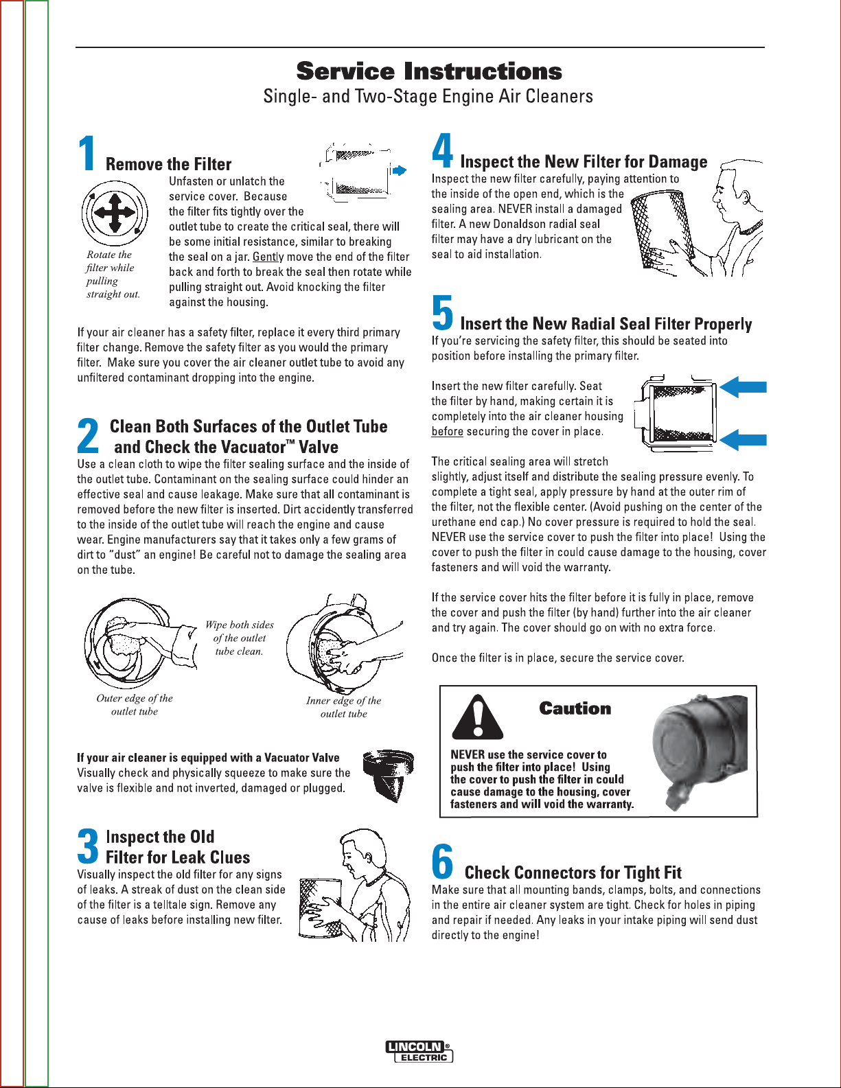
D-2 D-2
MAINTENANCE
Return to Master TOC Return to Master TOC Return to Master TOC Return to Master TOC
Return to Section TOC Return to Section TOC Return to Section TOC Return to Section TOC
BIG RED®500/600
Page 31

D-3 D-3
SAFETY PRECAUTIONS
WARNING
Have qualified personnel do the maintenance
work. Turn the engine off before working inside
the machine. In some cases, it may be
necessary to remove safety guards to perform
required maintenance. Remove guards only
when necessary and replace them when the
maintenance requiring their removal is
complete. Always use the greatest care when
working near moving parts.
Do not put your hands near the engine cooling
blower fan. If a problem cannot be corrected by
following the instructions, take the machine to
the nearest Lincoln Field Service Shop.
-----------------------------------------------------------------------
ELECTRIC SHOCK can kill.
• Do not touch electrically live parts or
electrode with skin or wet clothing.
• Insulate yourself from work and
ground
• Always wear dry insulating gloves.
------------------------------------------------------------------------
ENGINE EXHAUST can kill.
• Use in open, well ventilated areas or
vent exhaust outside.
MAINTENANCE
WEEKLY
Blow out the machine with low pressure air periodically. In particularly dirty locations, this may be required
once a week.
ENGINE MAINTENANCE
Refer to the “Periodic Checks” section of the Engine
Operatorʼs Manual for the recommended maintenance
schedule of the following:
a) Engine Oil and Filter
b) Air Cleaner
c) Fuel Filter - and Delivery System
d) Cooling Blower Belt
e) Battery
f) Cooling System
Refer to Table D.1 at the end of this section for various
engine maintenance components.
ENGINE OIL CHANGE
Drain the engine oil while the engine is warm to assure
rapid and complete draining. It is recommended that
each time the oil is changed the oil filter be changed as
well.
• Be sure the unit is off. Disconnect the negative battery cable to ensure safety.
------------------------------------------------------------------------
MOVING PARTS can injure.
• Do not operate with doors open or
guards off.
• Stop engine before servicing.
• Keep away from moving parts.
------------------------------------------------------------------------
See additional warning information
throughout this operatorʼs manual and the
Engine manual as well.
-----------------------------------------------------------
ROUTINE AND PERIODIC MAINTENANCE
DAILY
• Check the crankcase oil level .
• Refill the fuel tank to minimize moisture condensation in the tank.
• Open the water drain valve located on the bottom of
the water separator element 1 or 2 turns and allow to
drain into a container suitable for diesel fuel for 2 to
3 seconds. Repeat the above drainage procedure
until diesel fuel is detected in the co
• Locate oil drain hose and valve in bottom of base
and pull through the hole in the case back or side of
base on the welder.
• Remove the cap from the drain valve. Push valve in
and twist counterclockwise. Pull to open and drain
the oil into a suitable container for disposal.
• Close the drain valve by pushing in and twisting
clockwise. Replace the cap.
• Re-fill the crankcase to the upper limit mark on the
dipstick with the recommended oil (see engine operation manual OR engine service items decal OR
below). Replace and tighten the oil filler cap securely.
• Push oil drain hose and valve back into unit, re-connect negative battery cable, and close doors and
engine top cover before restarting unit. Wash your
hands with soap and water after handling used
motor oil. Please dispose of used motor oil in a manner that is compatible with the environment. We
suggest you take it in a sealed container to your local
service station or recycling center for reclamation.
DO NOT throw it in the trash; pour it on the ground
or down a drain.
Return to Master TOC Return to Master TOC Return to Master TOC Return to Master TOC
Return to Section TOC Return to Section TOC Return to Section TOC Return to Section TOC
BIG RED®500/600
Page 32

D-4 D-4
Use motor oil designed for diesel engines that meets
requirements for API service classification
CC/CD/CE/CF/CF-4/CG-4 or CH-4.
ACEA E1/E2/E3. Always check the API service label
on the oil container to be sure it includes the letters
indicated. (Note: An S-grade oil must not be used in a
diesel engine or damage may result. It IS permissible
to use an oil that meets S and C grade service classifications.)
SAE 10W30 is recommended for general, all temperature use, 5F to 104F (-15C to 40C).
See engine ownerʼs manual for more specific information on oil viscosity recommendations.
OIL FILTER CHANGE
• Drain the oil.
• Remove the oil filter with an oil filter wrench and drain
the oil into a suitable container. Discard the used filter. Note: Care should be taken during filter removal
to not disrupt or damage in any way the fuel lines.
• Clean the filter mounting base and coat the gasket
of the new filter with clean engine oil.
MAINTENANCE
3. Remove loose dirt from element with compressed
air or water hose directed from inside out.
Compressed Air: 100 psi maximum with nozzles
at least one inch away from element.
Water Hose: 40 psi maximum without nozzle.
4. Soak element in a mild detergent solution for 15
minutes. Do not soak more than 24 hours. Swish
element around in the solution to help remove dirt.
5. Rinse elements from inside out with a gentle stream
of water (less than 40 psi) to remove all suds and
dirt.
6. Dry element before reuse with warm air at less than
160°F (71°C). Do not use a light bulb to dry the element.
7. Inspect for holes and tears by looking through the
element toward a bright light. Check for damaged
gaskets or dented metal parts. Do not reuse damaged elements. Protect element from dust and damage during drying and storage.
8. Reinstall air filter element.
After six cleanings replace air filter. A cleaned filter
will have approximately 70% of the life of a new filter element. A restricted filter element may not
appear excessively dirty.
• Screw the new filter on by hand until the gasket contacts the mounting base. Using an oil filter wrench,
tighten the filter an additional 1/2 to 7/8 of a turn.
• Refill the crankcase with the specified amount of the
recommended engine oil. Reinstall the oil filler cap
and tighten securely.
• Start the engine and check for oil filter leaks.
• Stop the engine and check the oil level. If necessary,
add oil to the upper limit mark on the dipstick.
AIR FILTER
FUEL
USE DIESEL FUEL ONLY - Low Sulphur fuel
or ultra low sulphur fuel in USA and CANADA only.
At the end of each dayʼs use, refill the fuel tank to minimize moisture condensation and dirt contamination in
the fuel line. Do not overfill; leave room for the fuel to
expand.
Use only fresh No. 2D diesel fuel, the use of No. 1D
diesel fuel is recommended in place of No. 2D at temperatures below 23°F (-5°C). Do not use kerosene.
See the Engine Operator's Manual for instructions on
replacing the fuel filter.
CAUTION
EXCESSIVE AIR FILTER RESTRICTION WILL
RESULT IN REDUCED ENGINE LIFE.
------------------------------------------------------------------------
The air filter element is a dry cartridge type. It can be
cleaned and reused; however, damaged elements
should not be reused. Stop engine after 100 hours of
running time and clean filter element , replace the filter
if necessary. Service air cleaner regularly according to
Engine Operatorʼs Manual.
1. Locate the air filter canister located behind the
engine door on the top of the engine.
2. Remove air filter element.
Return to Master TOC Return to Master TOC Return to Master TOC Return to Master TOC
Return to Section TOC Return to Section TOC Return to Section TOC Return to Section TOC
BIG RED®500/600
BLEEDING THE FUEL SYSTEM
You may need to bleed air from the fuel system if the
fuel filter or fuel lines have been detached, the fuel tank
has been ran empty or after periods of long storage. It
is recommended that the fuel shutoff valve be closed
during periods of non-use.
WARNING
To avoid personal injury, do not bleed a hot engine.
This could cause fuel to spill onto a hot exhaust
manifold, creating a danger of fire.
------------------------------------------------------------------------
Page 33

D-5 D-5
MAINTENANCE
FUEL FILTERS
WARNING
When working on the fuel system
• Keep naked lights away, do not
smoke !
• Do not spill fuel !
------------------------------------------------------------------------
The BIG RED®500 is equipped with a Fuel
Filter/Water Separator Assembly located after the
lift pump and before the fuel injectors. The Fuel
Filter/Water Separator is mounted to the engine block
just left of the lift pump.
1. Close the fuel shutoff valve.
2. Clean the area around the fuel filter head. Remove
the filter. Clean the gasket surface of the filter head
and replace the o-ring.
3. Fill the clean filter with clean fuel, and lubricate the
o-ring seal with clean lubricating oil.
4. Install the filter as specified by the filter manufacturer.
WARNING
Mechanical overtightening will distort the threads,
filter element seal or filter can.
------------------------------------------------------------------------
BATTERY HANDLING
GASES FROM BATTERY can explode.
• Keep sparks, flame and cigarettes away
from battery.
To prevent EXPLOSION when:
• INSTALLING A NEW BATTERY - disconnect negative cable from old battery first
and connect to new battery last.
• CONNECTING A BATTERY CHARGER Remove battery from welder by disconnecting negative cable first, then positive
cable and battery clamp. When reinstalling, connect negative cable last.
Keep well ventilated.
• USING A BOOSTER - connect positive
lead to battery first then connect negative lead to engine foot.
BATTERY ACID CAN BURN EYES AND
SKIN.
• Wear gloves and eye protection and be
careful when working near battery.
Follow instructions printed on battery.
----------------------------------------------------------------------------
PREVENTING ELECTRICAL DAMAGE
1. When replacing, jumping, or otherwise connecting
the battery to the battery cables, the proper polarity
must be observed. Failure to observe the proper
polarity could result in damage to the charging circuit. The positive (+) battery cable has a red terminal cover.
2. If the battery requires charging from an external
charger, disconnect the negative battery cable first
and then the positive battery cable before attaching
the charger leads. Failure to do so can result in
damage to the internal charger components. When
reconnecting the cables, connect the positive cable
first and the negative cable last.
PREVENTING BATTERY DISCHARGE
Turn off the RUN/STOP to stop when engine is not running.
Return to Master TOC Return to Master TOC Return to Master TOC Return to Master TOC
Return to Section TOC Return to Section TOC Return to Section TOC Return to Section TOC
BIG RED®500/600
Page 34

D-6 D-6
MAINTENANCE
PREVENTING BATTERY BUCKLING
Tighten nuts on battery clamp until snug.
CHARGING THE BATTERY
When you charge, jump, replace, or otherwise connect
battery cables to the battery, be sure the polarity is correct. Improper polarity can damage the charging circuit. The Vantage positive (+) battery terminal has a
red terminal cover.
If you need to charge the battery with an external
charger, disconnect the negative cable first, then the
positive cable before you attach the charger leads.
After the battery is charged, reconnect the positive battery cable first and the negative cable last. Failure to do
so can result in damage to the internal charger components.
Follow the instructions of the battery charger manufacturer for proper charger settings and charging time.
SERVICING OPTIONAL SPARK
ARRESTOR
Clean every 100 hours.
WARNING
• MUFFLER MAY BE HOT
• ALLOW ENGINE TO COOL BEFORE INSTALLING
THE SPARK ARRESTER!
• DO NOT OPERATE ENGINE WHILE INSTALLING
THE SPARK ARRESTER!
------------------------------------------------------------------------
NAMEPLATES / WARNING DECALS
MAINTENANCE
Whenever routine maintenance is performed on this
machine - or at least yearly - inspect all nameplates
and labels for legibility. Replace those which are no
longer clear. Refer to the parts list for the replacement
item number.
Table D.1 Engine Maintenance Components
Return to Master TOC Return to Master TOC Return to Master TOC Return to Master TOC
Return to Section TOC Return to Section TOC Return to Section TOC Return to Section TOC
BIG RED®500/600
Page 35

D-7 D-7
MAINTENANCE
WELDER / GENERATOR MAINTENANCE
STORAGE
Store the BIG RED®500 in clean, dry protected areas.
CLEANING
Blow out the generator and controls periodically with
low pressure air. Do this at least once a week in particularly dirty areas.
BRUSH REMOVAL AND REPLACEMENT
It is normal for the brushes and slip rings to wear and
darken slightly. Inspect the brushes when a generator
overhaul is necessary.
WARNING
Do not attempt to polish slip rings while the engine
is running.
------------------------------------------------------------------------
GFCI MODULE TESTING AND RESETTING
PROCEDURE
The GFCI module should be properly tested at least
once every month or whenever it is tripped. To properly test and reset the GFCI module:
• If the module has tripped, first carefully remove any
load and check it for damage.
• If the equipment has been shut down, it must be
restarted.
• The equipment needs to be operating at high idle
speed and any necessary adjustments made on the
control panel so that the equipment is providing at
least 80 volts to the receptacle input terminals.
• The circuit breaker for this receptacle must not be
tripped. Reset if necessary.
• Push the "Reset" button located on the GFCI module. This will assure normal GFCI operation.
• Plug a night-light (with an "ON/OFF" switch) or other
product (such as a lamp) into the Duplex receptacle
and turn the product "ON".
• Push the "Test" button located on the GFCI module.
The night-light or other product should go "OFF".
• Push the "Reset" button, again. The light or other
product should go "ON" again.
If the light or other product remains "ON" when the
"Test" button is pushed, the GFCI module is not working properly or has been incorrectly installed (miswired). If your GFCI module is not working properly,
contact a qualified, certified electrician who can assess
the situation, rewire the GFCI module if necessary or
replace the device.
Return to Master TOC Return to Master TOC Return to Master TOC Return to Master TOC
Return to Section TOC Return to Section TOC Return to Section TOC Return to Section TOC
BIG RED®500/600
Page 36

D-8 D-8
1
3
4
5
6
8
9
7
2
FIGURE D.2 - MAJOR COMPONENT LOCATIONS
1. Case Front & Control Panel Assembly
2. Lower Control Panel Assembly
3. Reactor, Rectifier & Fuel Tank Assembly
4. Inner Control Panel Assembly
5. Base, Battery & Lift Bale Assembly
6. Engine & Filter Assembly
7. Generator Assembly
8. Case Back Assembly
9. Covers Assembly
MAINTENANCE
Return to Master TOC Return to Master TOC Return to Master TOC Return to Master TOC
Return to Section TOC Return to Section TOC Return to Section TOC Return to Section TOC
BIG RED®500/600
Page 37

D-9 D-9
NOTES
Return to Master TOC Return to Master TOC Return to Master TOC Return to Master TOC
Return to Section TOC Return to Section TOC Return to Section TOC Return to Section TOC
BIG RED®500/600
Page 38

NOTES
THIS SECTION FOR BIG RED®600 ONLY.
Return to Master TOC Return to Master TOC Return to Master TOC Return to Master TOC
Return to Section TOC Return to Section TOC Return to Section TOC Return to Section TOC
BIG RED®500/600
Page 39

AA-1 AA-1
Installation . . . . . . . . . . . . . . . . . . . . . . . . . . . . . . . . . . . . . . . . . . . . . . . . . . . . . . . . . . . . . . . . . . . . . . . . . . .AA-1
Technical Specifications . . . . . . . . . . . . . . . . . . . . . . . . . . . . . . . . . . . . . . . . . . . . . . . . . . . . . . . . . . . . . . .AA-2
TABLE OF CONTENTS - INSTALLATION SECTION
Safety Precautions . . . . . . . . . . . . . . . . . . . . . . . . . . . . . . . . . . . . . . . . . . . . . . . . . . . . . . . . . . . . . . .AA-3
Location and Ventilation . . . . . . . . . . . . . . . . . . . . . . . . . . . . . . . . . . . . . . . . . . . . . . . . . . . . . . . . . . .AA-3
Storing . . . . . . . . . . . . . . . . . . . . . . . . . . . . . . . . . . . . . . . . . . . . . . . . . . . . . . . . . . . . . . . . . . . . . . . . .AA-3
Stacking . . . . . . . . . . . . . . . . . . . . . . . . . . . . . . . . . . . . . . . . . . . . . . . . . . . . . . . . . . . . . . . . . . . . . . . .AA-3
Angle of Operation . . . . . . . . . . . . . . . . . . . . . . . . . . . . . . . . . . . . . . . . . . . . . . . . . . . . . . . . . . . . . . .AA-3
Lifting . . . . . . . . . . . . . . . . . . . . . . . . . . . . . . . . . . . . . . . . . . . . . . . . . . . . . . . . . . . . . . . . . . . . . . . . . .AA-3
High Altitude Operation . . . . . . . . . . . . . . . . . . . . . . . . . . . . . . . . . . . . . . . . . . . . . . . . . . . . . . . . . . . .AA-3
High Temperature Operation . . . . . . . . . . . . . . . . . . . . . . . . . . . . . . . . . . . . . . . . . . . . . . . . . . . . . . . .AA-3
Towing . . . . . . . . . . . . . . . . . . . . . . . . . . . . . . . . . . . . . . . . . . . . . . . . . . . . . . . . . . . . . . . . . . . . . . . . .AA-4
Vehicle Mounting . . . . . . . . . . . . . . . . . . . . . . . . . . . . . . . . . . . . . . . . . . . . . . . . . . . . . . . . . . . . . . . . .AA-4
Pre-Operation Engine Service . . . . . . . . . . . . . . . . . . . . . . . . . . . . . . . . . . . . . . . . . . . . . . . . . . . . . . . . . .AA-4
Oil . . . . . . . . . . . . . . . . . . . . . . . . . . . . . . . . . . . . . . . . . . . . . . . . . . . . . . . . . . . . . . . . . . . . . . . . . . . .AA-4
Fuel . . . . . . . . . . . . . . . . . . . . . . . . . . . . . . . . . . . . . . . . . . . . . . . . . . . . . . . . . . . . . . . . . . . . . . . . . . .AA-4
Engine Break-In . . . . . . . . . . . . . . . . . . . . . . . . . . . . . . . . . . . . . . . . . . . . . . . . . . . . . . . . . . . . . . . . . .AA-5
Engine Cooing System . . . . . . . . . . . . . . . . . . . . . . . . . . . . . . . . . . . . . . . . . . . . . . . . . . . . . . . . . . . .AA-5
Battery Connection . . . . . . . . . . . . . . . . . . . . . . . . . . . . . . . . . . . . . . . . . . . . . . . . . . . . . . . . . . . . . . .AA-5
Muffler Outlet Pipe . . . . . . . . . . . . . . . . . . . . . . . . . . . . . . . . . . . . . . . . . . . . . . . . . . . . . . . . . . . . . . . .AA-6
Spark Arrestor . . . . . . . . . . . . . . . . . . . . . . . . . . . . . . . . . . . . . . . . . . . . . . . . . . . . . . . . . . . . . . . . . . .AA-6
Welding Output Cables . . . . . . . . . . . . . . . . . . . . . . . . . . . . . . . . . . . . . . . . . . . . . . . . . . . . . . . . . . . . . . .AA-6
Machine Grounding . . . . . . . . . . . . . . . . . . . . . . . . . . . . . . . . . . . . . . . . . . . . . . . . . . . . . . . . . . . . . . . . . .AA-6
Auxiliary Power Receptacles, Residual Device Ready, Standby Power Connections . . . . . . . . . . . . . . .AA-7
Connection of Lincoln Electric Wire Feeders . . . . . . . . . . . . . . . . . . . . . . . . . . . . . . . . . . . . . . . . . . . . . . .AA-8
Return to Master TOC Return to Master TOC Return to Master TOC Return to Master TOC
BIG RED®500/600
Page 40

AA-2 AA-2
INSTALLATION
TECHNICAL SPECIFICATIONS - BIG RED®600
(K2811-1)
INPUT - DIESEL ENGINE
Make/Model Description Speed (RPM) Displacement Starting Capacities
System
Deutz 3 cylinder Idle 1890 173 cu. in 12VDC battery Fuel
F3L 912 44HP (33 kw) (2.83L) & Starter (20 US gal)
Diesel Engine @ 1800 RPM Full Load 1800 75.7L
Bore x Stroke
Oil:
3.94” x 4.72” 9.5 QTS.
(100mm x 120mm) 9.0L
RATED OUTPUT @ 104° F (40° C) - WELDER
Welding Process
DC Constant Current
TIG
Welding Output
Current/Voltage/Duty Cycle
500A / 40V / 100%
550A / 34V / 60%
600A / 30V / 40%
250A / 20V / 100%
Output Range
Amps
65A TO 600A
65A TO 250A
Max. Weld OCV
Voltage @ 1800RPM
90 Volts
75 Volts
RATED OUTPUT @ 104° F (40° C).- GENERATOR
1
AMPS
20
15
15
POWER
2400 Watts
1800 Watts
3600 Watts
OUTLETS
1
1
1
Auxiliary Power
Single Phase 60 Hz AC
VOLTS
120
120
240
RECEPTACLES AND CIRCUIT BREAKERS
RECEPTACLES AUXILIARY POWER CIRCUIT BREAKER OTHER CIRCUIT BREAKERS
1 - 120VAC Duplex NEMA(5-20R) GFCI protected
1 - 120VAC European (IEC-309)-GFCI protected
1 - 240VAC European (IEC-309)
1 - 20 AMP for 120 VAC Duplex (NEMA)
1 - 15 AMP for 120 VAC
1 - 15 AMP for 240 VAC
European (IEC-309)
European (IEC-309)
20AMP for Battery Charging Circuit
PHYSICAL DIMENSIONS
HEIGHT WIDTH DEPTH WEIGHT
(2)
36.87
916.5 mm 718.3 mm 1653.5 mm
1. Output rating in watts is equivalent to volt-amperes at unity power factor. Output voltage is within ± 10% at all loads up to
rated capacity. When welding, available auxiliary power will be reduced.
2. To Top of enclosure, add 8.28”(210.1mm) to top of exhaust pipe.
in. 28.28 in 65.1 in.
1657 lbs. (752 kg.)
Return to Master TOC Return to Master TOC Return to Master TOC Return to Master TOC
Return to Section TOC Return to Section TOC Return to Section TOC Return to Section TOC
BIG RED®500/600
Page 41

AA-3 AA-3
INSTALLATION
SAFETY PRECAUTION
Read this entire installation section before you start
installation.
WARNING
ELECTRIC SHOCK can kill.
• Do not touch electrically live parts or
electrode with skin or wet clothing.
• Insulate yourself from work and
ground
• Always wear dry insulating gloves.
------------------------------------------------------------------------
ENGINE EXHAUST can kill.
• Use in open, well ventilated areas or
vent exhaust outside.
------------------------------------------------------------------------
MOVING PARTS can injure.
• Do not operate with doors open or
guards off.
• Stop engine before servicing.
• Keep away from moving parts.
------------------------------------------------------------------------
See additional warning information at front
of this operatorʼs manual.
LOCATION AND VENTILATION
The welder should be located to provide an unrestricted flow of clean, cool air to the cooling air inlets and to
avoid restricting the cooling air outlets. Also, locate the
welder so that the engine exhaust fumes are properly
vented to an outside area.
STORING
1. Store the machine in a cool, dry place when it is
not in use. Protect it from dust and dirt. Keep it
where it canʼt be accidentally damaged from construction activities, moving vehicles, and other
hazards.
2. Drain the engine oil and refill with fresh 10W30 oil.
Run the engine for about five minutes to circulate
oil to all the parts. See the MAINTENANCE sec-
tion of this manual for details on changing oil.
3. Remove the battery, recharge it, and adjust the
electrolyte level. Store the battery in a dry, dark
place.
ANGLE OF OPERATION
To achieve optimum engine performance the BIG
®
600 should be run in a level position. The max-
RED
imum angle of operation for the Deutz engine is 30
degrees fore and aft, 40 degrees right and 45 degrees
left. If the engine is to be operated at an angle, provisions must be made for checking and maintaining the
oil level at the normal (FULL) oil capacity in the
crankcase. When operating the welder at an angle, the
effective fuel capacity will be slightly less than the
amount specified.
LIFTING
The BIG RED®600 weighs approximately 1772lbs.
(804kg.) with a full tank of fuel 1657lbs.(752kg) less
fuel. A lift bail is mounted to the machine and should
always be used when lifting the machine.
WARNING
• Lift only with equipment of adequate lifting capacity.
• Be sure machine is stable when lifting.
• Do not lift this machine using lift
bail if it is equipped with a heavy
accessory such as trailer or gas
cylinder.
FALLING • Do not lift machine if lift bail is
EQUIPMENT can damaged.
cause injury. • Do not operate machine while
suspended from lift bail.
--------------------------------------------------------------------------------
HIGH ALTITUDE OPERATION
At higher altitudes, output derating may be necessary.
For maximum rating, derate the welder output 5% for
every 300 meters (984 ft.) above 1500 meters (4920
ft.). For output of 500A and below, derate the welder
output 5% for every 300 meters (984 ft.) above 2100
meters (6888 ft.).
Contact a Deutz Service Representative for any
engine adjustments that may be required.
HIGH TEMPERATURE OPERATION
WELDER OUTPUT RATINGS AT
STACKING
AMPS DUTY CYCLE VOLTS TEMPERATURE
BIG RED®600 machines cannot be stacked.
Return to Master TOC Return to Master TOC Return to Master TOC Return to Master TOC
Return to Section TOC Return to Section TOC Return to Section TOC Return to Section TOC
BIG RED®500/600
450 DC 30% 38 55
500 DC 30% 40 50
550 DC 30% 34 45
TEMPERATURES ABOVE 40°C
°
C
°
C
°
C
Page 42

AA-4 AA-4
INSTALLATION
TOWING
Use a recommended trailer for use with this equipment
for road, in-plant and yard towing by a vehicle(1). If the
user adapts a non-Lincoln trailer, he must assume
responsibility that the method of attachment and usage
does not result in a safety hazard or damage the welding equipment. Some of the factors to be considered
are as follows:
1. Design capacity of trailer vs. weight of Lincoln equipment and likely additional attachments.
2. Proper support of, and attachment to, the base of
the welding equipment so there will be no undue
stress to the framework.
3. Proper placement of the equipment on the trailer to
insure stability side to side and front to back when
being moved and when standing by itself while
being operated or serviced.
4. Typical conditions of use, i.e., travel speed; roughness of surface on which the trailer will be operated;
environmental conditions; like maintenance.
5. Conformance with federal, state and local laws.
(1) Consult applicable federal, state and local laws regarding spe-
cific requirements for use on public highways.
(1)
VEHICLE MOUNTING
WARNING
Improperly mounted concentrated loads may
cause unstable vehicle handling and tires or other
components to fail.
• Only transport this Equipment on serviceable
vehicles which are rated and designed for such
loads.
• Distribute, balance and secure loads so vehicle
is stable under conditions of use.
• Do not exceed maximum rated loads for components such as suspension, axles and tires.
• Mount equipment base to metal bed or frame of
vehicle.
• Follow vehicle manufactureʼs instructions.
------------------------------------------------------------------------
PRE-OPERATION ENGINE SERVICE
READ the engine operating and maintenance instructions supplied with this machine.
WARNING
Stop engine while fueling.
• Do not smoke when fueling.
• Keep sparks and flame away from
tank.
• Do not leave unattended while
fueling.
DIESEL FUEL
can cause fire.
• Wipe up spilled fuel and allow
fumes to clear before starting
engine.
• Do not overfill tank, fuel expan-
sion may cause overflow.
DIESEL FUEL ONLY
------------------------------------------------------------------------------------------
OIL
The BIG RED®600 is shipped with the engine
crankcase filled with high quality SAE 10W-30 oil (API
class CD or better). Check the oil level before starting
the engine. If it is not up to the full mark on the dip stick,
add oil as required. Check the oil level every four hours
of running time during the first 35 running hours. Refer
to the engine Operatorʼs Manual for specific oil recommendations and break-in information. The oil change
interval is dependent on the quality of the oil and the
operating environment. Refer to the engine Operatorʼs
Manual for the proper service and maintenance intervals. The machine is equipped with an oil drain valve.
FUEL
USE DIESEL FUEL ONLY
WARNING
• Fill the fuel tank with clean, fresh fuel. The
capacity of the tank is 20 gals. (75.7 ltrs). When
the fuel gauge reads empty the tank contains
approximately 2 gals. (7.6ltrs.) of reserve fuel.
WARNING
NOTE: A fuel shut off valve is located on the pre-
filter/sediment filter. Which should be in the
closed position when the welder is not used
for extended periods of time.
------------------------------------------------------------------------
Return to Master TOC Return to Master TOC Return to Master TOC Return to Master TOC
Return to Section TOC Return to Section TOC Return to Section TOC Return to Section TOC
BIG RED®500/600
Page 43

AA-5 AA-5
INSTALLATION
ENGINE BREAK-IN
Lincoln Electric selects high quality, heavy-duty industrial engines for the portable welding machines we
offer. While it is normal to see a small amount of
crankcase oil consumption during initial operation,
excessive oil use, wetstacking (oil or tar like substance
at the exhaust port), or excessive smoke is not normal.
Larger machines with a capacity of 350 amperes and
higher, which are operated at low or no-load conditions
for extended periods of time are especially susceptible
to the conditions described above. To accomplish successful engine break-in, most diesel-powered equipment needs only to be run at a reasonably heavy load
within the rating of the welder for some period of time
during the engineʼs early life. However, if the welder is
subjected to extensive light loading, occasional moderate to heavy loading of the engine may sometimes be
necessary. Caution must be observed in correctly
loading a diesel/generator unit.
1. Connect the welder output studs to a suitable resistive load bank. Note that any
attempt to short the output studs by connecting the welding leads together, direct
shorting of the output studs, or connecting
the output leads to a length of steel will
result in catastrophic damage to the generator and voids the warranty.
2. Set the welder controls for an output current and voltage within the welder rating
and duty cycle. Note that any attempt to
exceed the welder rating or duty cycle for
any period of time will result in catastrophic
damage to the generator and voids the
warranty.
3. Periodically shut off the engine and check
the crankcase oil level.
ENGINE COOLING SYSTEM
The Deutz engine is air cooled by a belt driven axial
blower. The oil cooler and engine cooling fins should
be blown out with compressed air or steam to maintain
proper cooling (See the engine Owners Manual for
procedures and frequency).
BATTERY CONNECTION
WARNING
GASES FROM BATTERY can explode.
• Keep sparks, flame and cigarettes
away from battery.
To prevent EXPLOSION when:
• INSTALLING A NEW BATTERY — disconnect negative cable from old battery first and connect to
new battery last.
• CONNECTING A BATTERY CHARGER — remove
battery from welder by disconnecting negative
cable first, then positive cable and battery clamp.
When reinstalling, connect negative cable last.
Keep well ventilated.
• USING A BOOSTER — connect positive lead to
battery first then connect negative lead to negative battery lead at engine foot.
BATTERY ACID can burn eyes and skin.
• Wear gloves and eye protection and be
careful when working near battery.
• Follow instructions printed on battery.
IMPORTANT: To prevent ELECTRICAL DAMAGE
WHEN:
a) Installing new batteries.
b) Using a booster.
Use correct polarity — Negative Ground.
------------------------------------------------------------------------
The BIG RED
cable disconnected. Before you operate the machine,
make sure the Engine Switch is in the OFF position
and attach the disconnected cable securely to the negative (-) battery terminal.
Remove the insulating cap from the negative battery
terminal. Replace and tighten negative battery cable
terminal.
NOTE: This machine is furnished with a wet charged
®
600 is shipped with the negative battery
battery; if unused for several months, the battery may require a booster charge. Be sure to
use the correct polarity when charging the battery.
Return to Master TOC Return to Master TOC Return to Master TOC Return to Master TOC
Return to Section TOC Return to Section TOC Return to Section TOC Return to Section TOC
BIG RED®500/600
Page 44

AA-6 AA-6
INSTALLATION
MUFFLER OUTLET PIPE
Remove the plastic plug covering the muffler outlet
tube. Using the clamp provided secure the outlet pipe
to the outlet tube with the pipe positioned such that it
will direct the exhaust in the desired position
.
SPARK ARRESTOR
Some federal, state or local laws may require that
petrol or diesel engines be equipped with exhaust
spark arrestors when they are operated in certain locations where unarrested sparks may present a fire hazard. The standard muffler included with this welder
does not qualify as a spark arrestor. When required by
local regulations, a suitable spark arrestor, must be
installed and properly maintained.
CAUTION
An incorrect arrestor may lead to damage to the
engine or adversely affect performance.
------------------------------------------------------------------------
WELDING OUTPUT CABLES
With the engine off, connect the electrode and work
cables to the output studs. The welding process dictates the polarity of the electrode cable. These connections should be checked periodically and tightened
if necessary.
Listed in Table AA.1 are copper cable sizes recommended for the rated current and duty cycle. Lengths
stipulated are the distance from the welder to work and
back to the welder again. Cable sizes are increased for
greater lengths primarily for the purpose of minimizing
cable voltage drop.
Table AA.1 Combined Length of Electrode and
Work Cables.
MACHINE GROUNDING
Because this portable engine driven welder creates its
own power, it is not necessary to connect its frame to
an earth ground, unless the machine is connected to
premises wiring (home, shop, etc.).
To prevent dangerous electric shock, other equipment
powered by this engine driven welder must:
a) be grounded to the frame of the welder using a
grounding type plug,
or
b) be double insulated.
When this welder is mounted on a truck or trailer, its
frame must be securely connected to the metal frame
of the vehicle. When this engine driven welder is connected to premises wiring such as that in a home or
shop, its frame must be connected to the system earth
ground. See further connection instructions in the section entitled Standby Power Connections as well as
the article on grounding in the latest National Electrical
Code and the local codes.
In general, if the machine is to be grounded, it should
be connected with a #8 or larger copper wire to a solid
earth ground such as a metal ground stake going into
the ground for at least 10 Feet or to the metal framework of a building which has been effectively grounded. The National Electric Code lists a number of alternate means of grounding electrical equipment. A
machine grounding stud marked with the symbol is
provided on the front of the welder.
TOTAL COMBINED LENGTH OF ELECTRODE
AMPS Up to 150 ft. 150-200 ft. 200-250 ft.
@100% (Up to 45m) (45-60m) (60-75m)
Duty Cycle
500 3/0 AWG 3/0 AWG 4/0 AWG
95mm
Return to Master TOC Return to Master TOC Return to Master TOC Return to Master TOC
Return to Section TOC Return to Section TOC Return to Section TOC Return to Section TOC
AND WORK CABLES
2
95mm
2
120mm
2
BIG RED®500/600
Page 45

AA-7 AA-7
INSTALLATION
AUXILIARY POWER RECEPTACLES
The auxiliary power of the BIG RED®600 consists of
Single Phase 60Hz Power. Out put Voltage is within +/10% at loads up to rated capacity.
One 120VAC NEMA (5-20R) 20 amp duplex receptacle
is protected by a 20 amp circuit breaker that provides
2400 watts Peak / 2400 watts Continuous power.
Maximum current is 20 amps total.
One 120VAC European (IEC-309) 16 amp receptacle
is protected by a 15 amp circuit breaker that provides
1800 watts Peak / 1800 watts Continuous power.
Maximum current is 15 amps.
One 240VAC European (IEC-309) 16 amp receptacle
is protected by a 15 amp 2-pole circuit breaker that
provides 3600 watts Peak / 3600 watts Continuous
power. The 2-pole circuit breaker disconnects both hot
leads at the same time. Maximum current is 15 amps.
120 VOLT RECEPTACLES
A GFCI module protects, the two 120V Auxiliary Power
receptacles. A GFCI (Ground Fault Circuit Interrupter)
electrical receptacle is a device to protect against elec-
tric shock should a piece of defective equipment connected to it develop a ground fault. If this situation
should occur, the GFCI module will trip, removing voltage from the output of the receptacle. If a GFCI module is tripped see the MAINTENANCE section for
detailed information on testing and resetting it. A GFCI
module should be properly tested at least once every
month.
The 120 V auxiliary power receptacles should only be
used with three wire grounded type plugs or approved
double insulated tools with two wire plugs. The current
rating of any plug used with the system must be at
least equal to the current capacity of the associated
receptacle.
RESIDUAL CURRENT DEVICE READY
The BIG RED®600 is configured to allow for the addition of a Residual Current Device (RCD) to protect the
240V Single Phase Receptacle. The auxiliary power
area on the front panel of the BIG RED
hole sized and shaped to accept a typical 2-pole (RCD)
along with a protective rubber boot. A cover plate with
a label “RCD READY” covers the hole and secures a
mounting bracket on the backside of the panel.
NOTE: The (RCD) should be rated for at least 15
amps.
There are many suppliers of RCDʼs. One example is
Allen Bradley, part number 1492-RCD2A40.
The protective boot can be obtained from:
APM-Hexseal, part number HE-1035
See Section F Diagrams of the Operatorʼs Manual for
instructions on installing an RCD and protective rubber
boot.
®
600 has a
STANDBY POWER CONNECTIONS
The BIG RED®600 is suitable for temporary, standby
or emergency power using the engine manufacturerʼs
recommended maintenance schedule.
®
The BIG RED
standby power unit for 240 VAC(60Hz). Connections
must be made by a licensed electrician who can determine how the 120/240 VAC power can be adapted to
the particular installation and comply with all applicable
electrical codes.
Take necessary steps to assure load is limited to the
capacity of the BIG RED®600
600 can be permanently installed as a
WARNING
• Only a licensed, certified, trained electrician
should install the machine to a premises or residential electrical system. Be certain that:
• The installation complies with the National
Electrical Code and all other applicable electrical
codes.
• The premises is isolated and no feedback into the
utility system can occur. Certain state and local
laws require the premises to be isolated before
the generator is linked to the premises. Check
your state and local requirements.
------------------------------------------------------------------------
Return to Master TOC Return to Master TOC Return to Master TOC Return to Master TOC
Return to Section TOC Return to Section TOC Return to Section TOC Return to Section TOC
BIG RED®500/600
Page 46

AA-8 AA-8
INSTALLATION
CONNECTION OF LINCOLN ELECTRIC
WIRE FEEDERS
WARNING
Shut off Welder before making any electrical connections.
------------------------------------------------------------------------
The LN-15®Across-the-Arc model, LN-25®with or without an internal contactor, and LN-25®PRO may be
used with the BIG RED®600.
1. Shut the welder off.
2. For electrode Positive, connect the electrode cable
from the wire feeder to the “+” terminal of the welder
and work cable to the “-” terminal of the welder. For
electrode Negative, connect the electrode cable
from the wire feeder to the “-” terminal of the welder
and work cable to the “+” terminal of the welder.
3. Set the CV/CC mode of the wire feeder to CC.
(Refer to wire feeder operator manual for details on
setting the wire feeder in the CC mode and for setting welding parameters).
WARNING
If you are using an LN-25®without an internal contactor, the electrode will be energized when the
BIG RED
------------------------------------------------------------------------
The Wire Feeder sensor has full OCV potential
between spring clip and work return. Turn machine
off when attaching spring clip.
------------------------------------------------------------------------
Lincoln Electric does NOT recommend constant
current semiautomatic welding for applications
which need to meet specified weld metal chemical
or mechanical property requirements or weld quality requirements.
------------------------------------------------------------------------
®
600 is started.
4. Attach the single lead from the front of the wire feeder to work using the spring clip at the end of the lead.
This is a sense lead to supply current to the wire
feeder motor; it does not carry welding current.
5. When the gun trigger is closed, the current sensing
circuit will cause the wire to begin to feed and the
welding process is started.
®
NOTE: The LN-25
(K444-1) Remote Control Module
(K431) and Remote Cable (K432) cannot be
used with the BIG RED®600. See the appropriate connection diagram in Section F of the
Operatorʼs Manual.
FIGURE AA-1
BIG RED™ 600
Electrode
LN-15™ ACROSS THE ARC
LN-25™, LN-25™ PRO
Work clip
Wor k
Return to Master TOC Return to Master TOC Return to Master TOC Return to Master TOC
Return to Section TOC Return to Section TOC Return to Section TOC Return to Section TOC
BIG RED®500/600
Page 47

BB-1 BB-1
Operation . . . . . . . . . . . . . . . . . . . . . . . . . . . . . . . . . . . . . . . . . . . . . . . . . . . . . . . . . . . . . . . . . . . . . . . . . . . .BB-1
Safety Instructions . . . . . . . . . . . . . . . . . . . . . . . . . . . . . . . . . . . . . . . . . . . . . . . . . . . . . . . . . . . . . . . . . . .BB-2
General Description . . . . . . . . . . . . . . . . . . . . . . . . . . . . . . . . . . . . . . . . . . . . . . . . . . . . . . . . . . . . . . . . . .BB-2
Recommended Applications . . . . . . . . . . . . . . . . . . . . . . . . . . . . . . . . . . . . . . . . . . . . . . . . . . . . . . . . . . .BB-2
Generator . . . . . . . . . . . . . . . . . . . . . . . . . . . . . . . . . . . . . . . . . . . . . . . . . . . . . . . . . . . . . . . . . . . . . . . . . .BB-2
Controls and Settings . . . . . . . . . . . . . . . . . . . . . . . . . . . . . . . . . . . . . . . . . . . . . . . . . . . . . . . . . . . . . . . .BB-3
Welder Controls . . . . . . . . . . . . . . . . . . . . . . . . . . . . . . . . . . . . . . . . . . . . . . . . . . . . . . . . . . . . . . . . . .BB-3
Engine Controls . . . . . . . . . . . . . . . . . . . . . . . . . . . . . . . . . . . . . . . . . . . . . . . . . . . . . . . . . . . . . . . . . .BB-4
Auxiliary . . . . . . . . . . . . . . . . . . . . . . . . . . . . . . . . . . . . . . . . . . . . . . . . . . . . . . . . . . . . . . . . . . . . . . . .BB-4
TABLE OF CONTENTS - OPERATION SECTION
Engine Operation . . . . . . . . . . . . . . . . . . . . . . . . . . . . . . . . . . . . . . . . . . . . . . . . . . . . . . . . . . . . . . . . . . . .BB-5
Starting the Engine . . . . . . . . . . . . . . . . . . . . . . . . . . . . . . . . . . . . . . . . . . . . . . . . . . . . . . . . . . . . . . .BB-5
Cold Weather Starting and Operation . . . . . . . . . . . . . . . . . . . . . . . . . . . . . . . . . . . . . . . . . . . . . . . . .BB-5
Stoping the Engine . . . . . . . . . . . . . . . . . . . . . . . . . . . . . . . . . . . . . . . . . . . . . . . . . . . . . . . . . . . . . . .BB-5
Welding Operation . . . . . . . . . . . . . . . . . . . . . . . . . . . . . . . . . . . . . . . . . . . . . . . . . . . . . . . . . . . . . . . . . . .BB-6
Stick . . . . . . . . . . . . . . . . . . . . . . . . . . . . . . . . . . . . . . . . . . . . . . . . . . . . . . . . . . . . . . . . . . . . . . . . . . .BB-6
Arc Gouging . . . . . . . . . . . . . . . . . . . . . . . . . . . . . . . . . . . . . . . . . . . . . . . . . . . . . . . . . . . . . . . . . . . .BB-6
TIG Welding . . . . . . . . . . . . . . . . . . . . . . . . . . . . . . . . . . . . . . . . . . . . . . . . . . . . . . . . . . . . . . . . . . . . .BB-7
Constant Current Operation with Lincoln Wire Feeder . . . . . . . . . . . . . . . . . . . . . . . . . . . . . . . . . . . .BB-8
Auxiliary Power . . . . . . . . . . . . . . . . . . . . . . . . . . . . . . . . . . . . . . . . . . . . . . . . . . . . . . . . . . . . . . . . . . . . .BB-9
Simultaneous Welding and Power Loads . . . . . . . . . . . . . . . . . . . . . . . . . . . . . . . . . . . . . . . . . . . . . .BB-9
Return to Master TOC Return to Master TOC Return to Master TOC Return to Master TOC
BIG RED®500/600
Page 48

BB-2 BB-2
OPERATION
SAFETY INSTRUCTIONS
Read and understand this entire section before
operating your BIG RED
®
600.
WARNING
Do not attempt to use this equipment until you
have thoroughly read all operating and maintenance manuals supplied with your machine. They
include important safety precautions, detailed
engine starting, operating and maintenance
instructions and parts lists.
ELECTRIC SHOCK can kill.
• Do not touch electrically live parts
such as output terminals or internal
wiring.
• Insulate yourself from the work and
ground.
• Always wear dry insulating gloves.
------------------------------------------------------------------------
ENGINE EXHAUST can kill.
• Use in open, well ventilated areas or
vent exhaust outside
• Do not stack anything near the engine.
------------------------------------------------------------------------
MOVING PARTS can injure.
• Do not operate with doors open or
guards off.
• Stop engine before servicing.
• Keep away from moving parts
------------------------------------------------------------------------
Only qualified personnel should operate this
equipment.
------------------------------------------------------------------------
ADDITIONAL SAFETY PRECAUTIONS
GENERAL DESCRIPTION
The BIG RED®600 is a diesel engine driven welder,
offering reliable DC arc welding performance, with outstanding arc characteristics for all welding applications.
The BIG RED
diesel engine driven 600 amp DC arc welder and 3.6
KW AC power generator. This powerful generator can
be used to provide electricity for lights, power tools,
etc.
The BIG RED®600 delivers ideal DC arc characteristic
for each welding process. Stick electrode welding,
Scratch-Start TIG, or carbon arc gouging, to make the
BIG RED®600 the ideal all purpose engine driven
welder for on-site work.
The BIG RED®600 has “no PC Boards” and “no electronics”.
The BIG RED®600 is service friendly with a minimal
number of major parts, simplifying in field servicing of
the BIG RED®600. The generator is a dual stator and
rotor design with two sealed bearings for maintenance
free service. The rotors are copper wound design with
two slip rings and brushes. The stators are wound
entirely with heavy gauge copper wire and insulated
with NEMA class F insulation material. The stator is
then impregnated with three layers of high quality varnish. After the stator is assembled using tie bars, the
entire assembly Is covered with an environmentally
protective coating . These measures insure troublefree operation in the harshest environments.
®
600 is both a rugged three cylinder,
RECOMMENDED APPLICATIONS
WELDER
The BIG RED
ing output for stick (SMAW) and TIG (GTAW) welding
(scratch start). In addition the Big Red can be used for
Arc Gouging with carbons up to 9.5 mm (3/8”) diameter.
®
600 provides constant current DC weld-
Always operate the welder with the hinged door
closed and the side panels in place as these provide maximum protection from moving parts and
insure proper cooling air flow.
------------------------------------------------------------------------
Return to Master TOC Return to Master TOC Return to Master TOC Return to Master TOC
Return to Section TOC Return to Section TOC Return to Section TOC Return to Section TOC
BIG RED®500/600
The BIG RED®600 is not recommended for pipe
thawing.
GENERATOR
The BIG RED®600 provides smooth output for auxiliary power and emergency standby power. The auxiliary power is independent of the welding power and
thus not effected by the weld control settings. Full
power is available provided welding output is below
200 amps. Above 200 amps refer to the Simultaneous
Welding and Auxiliary Power chart in the operation
section of this manual.
Page 49

BB-3 BB-3
2
3
0
2
CONTROLS AND SETTINGS
All welder and engine controls are located on the case front panel. Refer to Figure BB.1 and the explanations that
follow.
Figure BB.1 Case Front Panel Controls
OPERATION
1
9
8
7
6
14
3
4
10
11
2
5
1
1
2
15
WELDING CONTROLS (Items 1-5)
1. OUTPUT RANGE SELECTOR SWITCH
A 5 position switch that provides 5 overlapping output current settings:
• 65 - 115
• 105 - 220
• 150 - 330
• 200 - 435
• 300 – Maximum
NOTE: Do not switch while welding
16
17
18
19
2
21
2. OUTPUT CONTROL
Provides fine adjustment of the current and open
circuit voltage from minimum to maximum within
each Range.
“1ʼʼ is minimum and “10” is maximum.
3. WELD MODE SELECTOR SWITCH
Provides selection of either Stick / Arc Gouging
Mode or TIG Mode.
4. VOLT/AMP METERS (optional)
Optional analog volt and amp meter kit available for
easy installation into front panel.
Return to Master TOC Return to Master TOC Return to Master TOC Return to Master TOC
Return to Section TOC Return to Section TOC Return to Section TOC Return to Section TOC
BIG RED®500/600
(See Accessory Section For “K” number)
Page 50

BB-4 BB-4
5. LOCAL / REMOTE CONTROL SWITCH and
REMOTE RECEPTACLE
OPERATION
11. OIL PRESSURE GAUGE
An indicator of engine oil pressure.
The toggle switch provides the option of controlling
the welding output at the control panel or remotely.
For control at the control panel set the switch in the
"LOCAL" position. For remote control set the switch
in the "REMOTE" position. The receptacle is for
attaching an optional remote control equipment.
(See Accessory Section For “K” number)
ENGINE CONTROLS (Items 6 Through to
13)
6. ENGINE HOUR METER / FUEL GAUGE
Combination hour meter fuel level gauge. The hour
meter displays the total time that the engine has
been running. This meter is a useful indicator for
scheduling preventive maintenance. The fuel gauge
displays the level of diesel fuel in the fuel tank. The
operator must watch the fuel level closely to prevent
running out of fuel and possibly having to bleed the
system.
7. RUN STOP SWITCH
The RUN position energizes the hold coil of the fuel
solenoid, hour meter, and rotor flashing circuit. The
STOP position stops the engine.
NOTE: Do not leave switch in RUN position when
the engine is not running. In the RUN position the battery will be discharged.
8. START PUSH BUTTON
Energizes the starter motor to crank the engine.
With the RUN / STOP switch in the RUN position,
push and hold the Start button to crank the engine;
release as the engine starts. Do not press while
engine is running as this can cause damage to the
ring gear and/or starter motor.
12. ENGINE PROTECTION
A warning indicator light for high oil temperature or
low oil pressure. The light remains off with proper
oil temperature and proper oil pressure. If a fault is
detected the light will turn on and the engine protection system will stop the engine. The light will
remain on when the engine has been shut down.
In order to try and re-start the engine the engine
protection system must be reset by returning the
RUN-STOP switch to the STOP position.
NOTE: The light remains off when the RUN-STOP
switch is in the RUN position prior to starting the engine. However if the engine is not
started within 60 seconds the light will come
on. When this happens the RUN-STOP
switch must be returned to the STOP position to reset the engine protection system
and light.
13. BATTERY CHARGING LIGHT
An indicator light for low/no battery charging. The
light is off when the battery charging system is
functioning normally. If light turns on, the alternator
or the voltage regulator may not be operating correctly or the cooling blower belt may be broken.
The light will remain on when the engine is
stopped and the RUN / STOP switch is in the RUN
position.
AUXILIARY POWER (14-22)
14. CIRCUIT BREAKER
2-pole 15A rated. Provides overload protection for
the 240VAC European (IEC-309) receptacle.
9. CIRCUIT BREAKER
The battery circuit breaker protects the engine circuitry that powers the three gauges, fuel/hours, temperature and pressure. It also protects the engine
shutdown relay, timer delay relay, hot start relay
hold solenoid, and flashing circuitry. When the circuit breaker opens because of a fault, the engine
will crank but will not start.
10. OIL TEMPERATURE GAUGE
An indicator of engine oil temperature.
Return to Master TOC Return to Master TOC Return to Master TOC Return to Master TOC
Return to Section TOC Return to Section TOC Return to Section TOC Return to Section TOC
BIG RED®500/600
15. 240 VAC RECEPTACLE
European (IEC-309) receptacle rated up to 15
amps and is IP44 rated.
NOTE: A space is provided on the panel for adding a
2-pole Residual Current Device (RCD) to protect the 240V receptacle. See Section F of the
Operatorʼs Manual for instructions on installing
an RCD.
16. CIRCUIT BREAKER
Single-pole 20A rated. Provides overload protection for the 120VAC (5-20R) NEMA Duplex
Receptacle.
Page 51

BB-5 BB-5
17. 120 VAC DUPLEX RECEPTACLE
Single-pole 20A rated. Provides overload protection for the 120VAC (5-20R) NEMA Duplex
OPERATION
8. Allow the engine to warm up for several minutes
before applying a load. Allow a longer warm up time
in cold weather.
Receptacle.
18. CIRCUIT BREAKERS
Single pole 15A rated. Provides overload protection for the 120VAC European (IEC-309) receptacle.
19. 120 VAC RECEPTACLE
European (IEC-309) receptacle rated up to 15
amps and is IP44 rated. Receptacle is GFCI pro-
COLD WEATHER STARTING
With a fully charged battery and the proper weight
oil, the engine should start satisfactorily even down
to about -15°C(5°F). If the engine must be frequently started below -15°C(5°F), it may be desirable to
install additional starting aids. The use of No. 1D
diesel fuel is recommended in place of No. 2D at
temperatures below -5°C(23° F).
tected.
STOPPING THE ENGINE
20. GFCI (Ground Fault Circuit Interrupter) Module
Protects both 120VAC Auxiliary Power receptacles.
If a GFCI Module is tripped, See the MAINTE-
NANCE section for detailed information on testing
and resetting the GFCI Module.
Switch the RUN/STOP switch to “STOP”. This turns
off the voltage supplied to the shutdown solenoid. A
backup shutdown can be accomplished by shutting
off the fuel valve located on the fuel line.
NOTE: Also put Run/Stop switch in “Stop” position
when engine is not running - battery will be discharged otherwise.
21. WELD OUTPUT TERMINALS + AND -
Covered terminals that provide welding connection
points for the electrode and work cables.
22. GROUND STUD
Protects both 120VAC Auxiliary Power receptacles.
ENGINE OPERATION
STARTING THE ENGINE
1. Open the engine compartment door and check that
the fuel shut off valve located screwed into the fuel
filter housing is in the open position (lever to be in
line with the hose).
2. Check for proper oil level. Close engine compartment door.
3. Remove all plugs connected to the AC power receptacles.
4. Set the RUN/STOP switch to “RUN”. Observe that
the battery charging light is on and fuel is in the fuel
tank (see fuel gauge).
5. Within 30 seconds, press and hold the engine
START button until the engine starts.
6. Release the engine START button when the engine
starts.
7. Check that the engine protection and battery charging lights are off. The engine protection light is on
after starting, the engine will shutdown in a few seconds. Investigate any indicated problem.
TABLE BB.1
TYPICAL
High Idle - No Load
1890 R.P.M.
DC, CC Weld Output
500A/40V/100%
DC, CC Weld Output
600A/30V/40%
Auxiliary Power
3.6 Kw
BIG RED®600
Deutz F3L912 Engine
44HP (33Kw) @ 1800 RPM
FUEL CONSUMPTION
2.6 liters/hr
(.69 gal/hr)
7.5 liters/hr
(1.97 gal/hr)
4.4 liters/hr
(1.16 gal/hr)
3.0 liters/hr
(.78 gal/hr)
Running Time for
75.7 L (20 Gal.)
28.9 hrs
10.1 hrs
17.2 hrs
25.5 hrs
NOTE: This data is for reference only. Fuel consump-
tion is approximate and can be influenced by
many factors, including engine maintenance,
environmental conditions and fuel quality.
Return to Master TOC Return to Master TOC Return to Master TOC Return to Master TOC
Return to Section TOC Return to Section TOC Return to Section TOC Return to Section TOC
BIG RED®500/600
Page 52

BB-6 BB-6
OPERATION
WELDER OPERATION
DUTY CYCLE
Duty Cycle is the percentage of time the load is
being applied in a 10 minute period. For example a
60% duty cycle, represents 6 minutes of load and 4
minutes of no load in a 10 minute period.
ELECTRODE INFORMATION
The BIG RED
cal up, and overhead welding with all types of DC
stick electrodes.
For any electrode the procedures should be kept
within the rating of the machine. For information on
electrodes and their proper application see
(www.lincolnelectric.com) or the appropriate
Lincoln publication.
WELDING MODE
Set the Welding mode switch for the desired
process, either Stick / Gouging or TIG.
CONSTANT CURRENT STICK WELDING
®
600 is designed for horizontal, verti-
CAUTION
DO NOT TURN THE “OUTPUT RANGE SELECTOR”
WHILE WELDING because the current may arc
between the contacts and damage the switch.
------------------------------------------------------------------------
For example: to obtain 175 amps and a forceful arc,
set the “Output Range Selector” to the 150-330
position and the “Output Current Adjustment” setting
to get 175 amps.
Some arc instability may be experienced with
EXX10 electrodes when trying to operate with long
arc techniques at settings at the lower end of the
open circuit voltage range.
CAUTION
DO NOT attempt to set the “Current Range
Selector” between the five points designated on
the nameplate.
------------------------------------------------------------------------
ARC GOUGING
Using the “Output Range Selector” and “Output
Control Adjustment” set the output to the desired
level for the gouging electrode being used see table
BB.2.
TABLE BB.2
Carbon Diameter Current Range (DC, elec-
trode positive)
1/8"(3.2mm) 60-90 Amps
5/32"(4.0mm) 90-150 Amps
3/16"9(4.8mm) 200-250 Amps
The “Output Range Selector” provides five overlapping current ranges. The “Output Current
Adjustment” adjusts the current from minimum to
maximum within each range. Open circuit voltage is
also controlled by the “Output Current Adjustment”
permitting control of the arc characteristics.
A high open circuit voltage setting provides the soft
“buttering” arc with best resistance to pop-outs preferred for most welding. To get this characteristic,
set the “Output Range Selector” to the lowest setting that still provides the current you need and set
the “Output Current Adjustment” near maximum.
For example: to obtain 175 amps and a soft arc, set
the “Output Range Selector” to the 105-220 position
and then adjust the “Output Current Adjustment” to
get 175 amps.
When a forceful “digging” arc is required, usually for
vertical and overhead welding, use a higher “Output
Range Selector” setting and lower open circuit voltage.
Return to Master TOC Return to Master TOC Return to Master TOC Return to Master TOC
Return to Section TOC Return to Section TOC Return to Section TOC Return to Section TOC
BIG RED®500/600
1/4"(6.4mm) 300-400 Amps
5/16"(8.0mm) 350-450 Amps
3/8"(9.5mm) 450-600 Amps
Page 53

BB-7 BB-7
OPERATION
TIG
The BIG RED®600 can be used for Scratch-Start of
DC TIG welding applications.
Use the “Output Range Selector” and “Output
Control Adjustments” to set the desired current. To
initiate a weld, the tungsten electrode is then
scratched on the work which establishes the arc. To
stop the arc, simply lift the TIG torch away from the
work piece. The tungsten may then be scratched on
the work piece to restrike the arc.
If a high frequency start is desired, the K930-2 TIG
Module can be used with the BIG RED
®
BIG RED
600 and any high frequency generating
®
600. The
equipment must be properly grounded. See the
K930-2 TIG Module operating manuals for complete
instructions on installation, operation, and maintenance.
When using the TIG Module, the OUTPUT control
on the BIG RED®600 is used to set the maximum
range of the CURRENT CONTROL on the TIG
Module or an Amptrol if connected to the TIG
Module.
TABLE BB.3
TYPICAL CURRENT RANGES
Tungsten Electrode DCEN (-) DCEP (+) Approximate Argon Gas Flow TIG TORCH
Diameter in. (mm) Flow Rate C.F.H. ( l /min.) Nozzle Size (4), (5)
1%, 2% Thoriated 1%, 2% Thoriated Aluminum Stainless Steel
Tungsten Tungsten
.010 (.25) 2-15 (3) 3-8 (2-4) 3-8 (2-4) #4, #5, #6
0.020 (.50) 5-20 (3) 5-10 (3-5) 5-10 (3-5)
0.040 (1.0) 15-80 (3) 5-10 (3-5) 5-10 (3-5)
1/16 (1.6) 70-150 10-20 5-10 (3-5) 9-13 (4-6) #5, #6
3/32 (2.4) 150-250 15-30 13-17 (6-8) 11-15 (5-7) #6, #7, #8
1/8 (3.2) 250-400 25-40 15-23 (7-11) 11-15 (5-7)
5/32 (4.0) 400-500 40-55 21-25 (10-12) 13-17 (6-8) #8, #10
3/16 (4.8) 500-750 55-80 23-27 (11-13) 18-22 (8-10)
1/4 (6.4) 750-1000 80-125 28-32 (13-15) 23-27 (11-13)
(1)
FOR TUNGSTEN ELECTRODES
(2)
(1) When used with argon gas. The current ranges shown must be reduced when using argon/helium or pure helium shielding gases.
(2) Tungsten electrodes are classified as follows by the American Welding Society (AWS):
Pure EWP
1% Thoriated EWTh-1
2% Thoriated EWTh-2
Though not yet recognized by the AWS, Ceriated Tungsten is now widely accepted as a substitute for 2% Thoriated Tungsten in AC and DC applications.
(3) DCEP is not commonly used in these sizes.
(4) TIG torch nozzle "sizes" are in multiples of 1/16ths of an inch:
(5) TIG torch nozzles are typically made from alumina ceramic. Special applications may require lava nozzles, which are less prone to breakage, but cannot withstand high temperatures
Return to Master TOC Return to Master TOC Return to Master TOC Return to Master TOC
Return to Section TOC Return to Section TOC Return to Section TOC Return to Section TOC
# 4 = 1/4 in. (6 mm)
# 5 = 5/16 in. (8 mm)
# 6 = 3/8 in. (10 mm)
# 7 = 7/16 in. (11 mm)
# 8 = _ in. (12.5 mm)
#10 = 5/8 in. (16 mm)
and high duty cycles.
BIG RED®500/600
Page 54

BB-8 BB-8
OPERATION
CONSTANT CURRENT OPERATION WITH
A LINCOLN ELECTRIC WIRE FEEDER
Lincoln Electric does NOT recommend constant
current semiautomatic welding for applications
which need to meet specified weld metal chemical
or mechanical property requirements or weld quality requirements.
------------------------------------------------------------------------
Most semiautomatic welding processes perform better
using constant voltage power sources. Welding codes
usually do not address the power source selection or
specifically, whether the welding process is to be operated in the constant voltage or constant current mode.
Instead, codes typically specify limitations on the current, voltage, heat input and preheat temperature
based on the material to be welded. The intention is to
assure that proper weld material properties will develop. Welding is sometimes performed using constant
current power sources. The operation can be more
convenient because it may allow the use of an existing
stick (SMAW) power source and the power source can
be placed at a distant location without any provision for
adjusting the output settings.
However, a constant current power source does not
provide such a response to stabilize the arc. It may be
difficult to achieve required weld metal properties, or to
achieve the required quality of welds needed to pass
nondestructive tests, when such welds are made
under constant current operation.
For constant current operation, the power source is set
to deliver the specified current. The power source regulates this current regardless of changes in the welding circuit, including cable length, electrode diameter,
wire feed speed, contact tip to work distance, etc.
Changes in the wire feed speed (WFS) or contact tip to
work distance (CTWD) affect the arc voltage when
constant current power sources are used. Lowering
the wire feed speed raises the voltage, raising the wire
feed speed lowers the voltage. Lengthening the contact tip to work distance raises the voltage, shortening
the contact tip to work distance lowers the voltage. If
the contact tip to work distance is properly maintained,
a satisfactory operating voltage range may be
achieved, and a sound weld may result. However,
when a welder uses a longer contact tip to work distance, an arc-sensing wire feeder compensates by
increasing the wire feed speed to regulate the voltage.
Even if the voltage and current remain unchanged, the
increased wire feed speed may result in a deposition
rate well beyond the specified range of the electrode.
Under these conditions, the specified weld metal properties may not be achieved. Constant voltage power
sources deliver large current surges to stabilize the arc
when the electrode is shorted or the arc length is very
short.
Return to Master TOC Return to Master TOC Return to Master TOC Return to Master TOC
Return to Section TOC Return to Section TOC Return to Section TOC Return to Section TOC
BIG RED®500/600
Page 55

BB-9 BB-9
OPERATION
AUXILIARY POWER:
The auxiliary power is independent of the welding
power and thus not effected by the weld control settings.
Simultaneous Welding and Auxiliary Power Loads
The auxiliary power ratings are with no welding load.
Simultaneous welding and power loads are specified
in the following Table BB.4.
TABLE BB.4
BIG RED®600 Simultaneous Welding and Power Loads
Current
(Amps)
15
20
15
Voltage
Volts
120
120
240
Weld
Amps
0
100
200
300
400
500
600
PLUS
1 PHASE (120V)
WATTS AMPS
2400 20
2400 20
2400 20
2400 20
1200 10
0 0
0 0
1 PHASE (240V)
WATTS AMPS
3600 15
3600 15
OR
3600 15
2400 10
1200 5
0 0
0 0
TABLE BB.5
BIG RED®600 Extension Cord Length Recommendations
(Use the shortest length extension cord possible sized per the following table.)
Load
(Watts)
1800
2400
36003060
14 AWG 12 AWG 10 AWG 8 AWG 6 AWG 4 AWG
(9)
(18)
Conductor size is based on maximum 2.0% voltage drop.
Maximum Allowable Cord Length in ft. (m) for Conductor Size
40
30
75
(12)
(9)
(23)
75
50
150
(23)
(15)
(46)
125
88
225
(38)
(27)
(69)
175
138
350
(53)
(42)
(107)
300
225
600
(91)
(69)
(183)
Return to Master TOC Return to Master TOC Return to Master TOC Return to Master TOC
Return to Section TOC Return to Section TOC Return to Section TOC Return to Section TOC
BIG RED®500/600
Page 56

BB-10 BB-10
NOTES
Return to Master TOC Return to Master TOC Return to Master TOC Return to Master TOC
Return to Section TOC Return to Section TOC Return to Section TOC Return to Section TOC
BIG RED®500/600
Page 57

CC-1 CC-1
Accessories . . . . . . . . . . . . . . . . . . . . . . . . . . . . . . . . . . . . . . . . . . . . . . . . . . . . . . . . . . . . . . . . . . . . . . . . . .CC-1
Optional Features . . . . . . . . . . . . . . . . . . . . . . . . . . . . . . . . . . . . . . . . . . . . . . . . . . . . . . . . . . . . . . . . . . .CC-2
TABLE OF CONTENTS - ACCESSORIES SECTION
Return to Master TOC Return to Master TOC Return to Master TOC Return to Master TOC
BIG RED®500/600
Page 58

CC-2 CC-2
ACCESSORIES
OPTIONAL FEATURES
K2641-2 FOUR WHEELED STEERABLE YARD
TRAILER
For in plant and yard towing. Comes standard with a
Duo-Hitch
Hitch.
K2636-1 TRAILER - Two-wheeled trailer with optional
fender and light package. For highway use, consult
applicable federal, state, and local laws regarding possible additional requirements. Comes standard with a
Duo-Hitch
hitch.
Order:
K2636-1 Trailer
K2639-1 Fender & Light Kit
K2640-1 Cable Storage Rack
K704 ACCESSORY SET - Includes 35 ft. (10m) of
electrode cable and 30 ft. (9.1m) of work cable, headshield, work clamp electrode holder. Cables are rated
at 400 amps, 100% duty cycle.
K2861-1 REMOTE CONTROL - 100 ft. (30.4m)
Portable control provides same dial range as the output control on the welder. Has a convenient twist-lock
plug for easy connection to the welder.
®
, a 2” Ball and Lunette Eye combination
®
, a 2” Ball and Lunette Eye combination
K2863-1 METER KIT
Easy-to-read analog meters for volts and amps. Easy
to install.
K2864-1 SPARK ARRESTOR - Includes a heavy gage
steel, approved spark arrestor, attaches to the muffler
exhaust tube. Includes clamp.
Return to Master TOC Return to Master TOC Return to Master TOC Return to Master TOC
Return to Section TOC Return to Section TOC Return to Section TOC Return to Section TOC
BIG RED®500/600
Page 59

DD-1 DD-1
Maintenance . . . . . . . . . . . . . . . . . . . . . . . . . . . . . . . . . . . . . . . . . . . . . . . . . . . . . . . . . . . . . . . . . . . . . . . . . .DD-1
Service Instructions . . . . . . . . . . . . . . . . . . . . . . . . . . . . . . . . . . . . . . . . . . . . . . . . . . . . . . . . . . . . . . . . . .DD-2
Safety Precautions . . . . . . . . . . . . . . . . . . . . . . . . . . . . . . . . . . . . . . . . . . . . . . . . . . . . . . . . . . . . . . . . . .DD-3
Routine and Periodic Engine Maintenance . . . . . . . . . . . . . . . . . . . . . . . . . . . . . . . . . . . . . . . . . . . . . . . .DD-3
TABLE OF CONTENTS - MAINTENANCE SECTION
Oil Filter Change . . . . . . . . . . . . . . . . . . . . . . . . . . . . . . . . . . . . . . . . . . . . . . . . . . . . . . . . . . . . . . . . .DD-4
Air Filter Change . . . . . . . . . . . . . . . . . . . . . . . . . . . . . . . . . . . . . . . . . . . . . . . . . . . . . . . . . . . . . . . . .DD-4
Fuel and Bleeding the Fuel System . . . . . . . . . . . . . . . . . . . . . . . . . . . . . . . . . . . . . . . . . . . . . . . . . .DD-4
Fuel Filters . . . . . . . . . . . . . . . . . . . . . . . . . . . . . . . . . . . . . . . . . . . . . . . . . . . . . . . . . . . . . . . . . . . . .DD-5
Fuel Pre-Filter/Water Separator Assembly . . . . . . . . . . . . . . . . . . . . . . . . . . . . . . . . . . . . . . . . . . . . .DD-5
Water Separator Element . . . . . . . . . . . . . . . . . . . . . . . . . . . . . . . . . . . . . . . . . . . . . . . . . . . . . . . . . .DD-5
Secondary Fuel Filter . . . . . . . . . . . . . . . . . . . . . . . . . . . . . . . . . . . . . . . . . . . . . . . . . . . . . . . . . . . . .DD-6
Cooling System . . . . . . . . . . . . . . . . . . . . . . . . . . . . . . . . . . . . . . . . . . . . . . . . . . . . . . . . . . . . . . . . . .DD-6
Cooling Blower Belt . . . . . . . . . . . . . . . . . . . . . . . . . . . . . . . . . . . . . . . . . . . . . . . . . . . . . . . . . . . . . . .DD-6
Battery Handling . . . . . . . . . . . . . . . . . . . . . . . . . . . . . . . . . . . . . . . . . . . . . . . . . . . . . . . . .DD-6 thru DD-7
Servicing Optional Spark Arrestor . . . . . . . . . . . . . . . . . . . . . . . . . . . . . . . . . . . . . . . . . . . . . . . . . . . . . . .DD-7
Nameplates / Warning Decals . . . . . . . . . . . . . . . . . . . . . . . . . . . . . . . . . . . . . . . . . . . . . . . . . . . . . .DD-7
Welder / Generator Maintenance . . . . . . . . . . . . . . . . . . . . . . . . . . . . . . . . . . . . . . . . . . . . . . . . . . . . . . .DD-8
Storage . . . . . . . . . . . . . . . . . . . . . . . . . . . . . . . . . . . . . . . . . . . . . . . . . . . . . . . . . . . . . . . . . . . . . . . .DD-8
Cleaning . . . . . . . . . . . . . . . . . . . . . . . . . . . . . . . . . . . . . . . . . . . . . . . . . . . . . . . . . . . . . . . . . . . . . . .DD-8
Brush Removal and Replacement . . . . . . . . . . . . . . . . . . . . . . . . . . . . . . . . . . . . . . . . . . . . . . . . . . .DD-8
GFCI Module Testing and Resetting Procedure . . . . . . . . . . . . . . . . . . . . . . . . . . . . . . . . . . . . . . . . .DD-8
Major Component Locations . . . . . . . . . . . . . . . . . . . . . . . . . . . . . . . . . . . . . . . . . . . . . . . . . . . . . . . . . . .DD-9
Return to Master TOC Return to Master TOC Return to Master TOC Return to Master TOC
BIG RED®500/600
Page 60

DD-2 DD-2
MAINTENANCE
Return to Master TOC Return to Master TOC Return to Master TOC Return to Master TOC
Return to Section TOC Return to Section TOC Return to Section TOC Return to Section TOC
BIG RED®500/600
Page 61

DD-3 DD-3
SAFETY PRECAUTIONS
WARNING
Have qualified personnel do the maintenance
work. Turn the engine off before working inside
the machine. In some cases, it may be
necessary to remove safety guards to perform
required maintenance. Remove guards only
when necessary and replace them when the
maintenance requiring their removal is
complete. Always use the greatest care when
working near moving parts.
Do not put your hands near the engine cooling
blower fan. If a problem cannot be corrected by
following the instructions, take the machine to
the nearest Lincoln Field Service Shop.
-----------------------------------------------------------------------
ELECTRIC SHOCK can kill.
• Do not touch electrically live parts or
electrode with skin or wet clothing.
• Insulate yourself from work and
ground
• Always wear dry insulating gloves.
------------------------------------------------------------------------
ENGINE EXHAUST can kill.
• Use in open, well ventilated areas or
vent exhaust outside.
MAINTENANCE
WEEKLY
Blow out the machine with low pressure air periodically. In particularly dirty locations, this may be required
once a week.
ENGINE MAINTENANCE
Refer to the “Periodic Checks” section of the Engine
Operatorʼs Manual for the recommended maintenance
schedule of the following:
a) Engine Oil and Filter
b) Air Cleaner
c) Fuel Filter - and Delivery System
d) Cooling Blower Belt
e) Battery
f) Cooling System
Refer to Table DD.1 at the end of this section for various engine maintenance components.
ENGINE OIL CHANGE
Drain the engine oil while the engine is warm to assure
rapid and complete draining. It is recommended that
each time the oil is changed the oil filter be changed as
well.
• Be sure the unit is off. Disconnect the negative battery cable to ensure safety.
------------------------------------------------------------------------
MOVING PARTS can injure.
• Do not operate with doors open or
guards off.
• Stop engine before servicing.
• Keep away from moving parts.
------------------------------------------------------------------------
See additional warning information
throughout this operatorʼs manual and the
Engine manual as well.
-----------------------------------------------------------
ROUTINE AND PERIODIC MAINTENANCE
DAILY
• Check the crankcase oil level .
• Refill the fuel tank to minimize moisture condensation in the tank.
• Open the water drain valve located on the bottom of
the water separator element 1 or 2 turns and allow to
drain into a container suitable for diesel fuel for 2 to
3 seconds. Repeat the above drainage procedure
until diesel fuel is detected in the co
• Locate oil drain hose and valve in bottom of base
and pull through the hole in the case back or side of
base on the welder.
• Remove the cap from the drain valve. Push valve in
and twist counterclockwise. Pull to open and drain
the oil into a suitable container for disposal.
• Close the drain valve by pushing in and twisting
clockwise. Replace the cap.
• Re-fill the crankcase to the upper limit mark on the
dipstick with the recommended oil (see engine operation manual OR engine service items decal OR
below). Replace and tighten the oil filler cap securely.
• Push oil drain hose and valve back into unit, re-connect negative battery cable, and close doors and
engine top cover before restarting unit. Wash your
hands with soap and water after handling used
motor oil. Please dispose of used motor oil in a manner that is compatible with the environment. We
suggest you take it in a sealed container to your local
service station or recycling center for reclamation.
DO NOT throw it in the trash; pour it on the ground
or down a drain.
Return to Master TOC Return to Master TOC Return to Master TOC Return to Master TOC
Return to Section TOC Return to Section TOC Return to Section TOC Return to Section TOC
BIG RED®500/600
Page 62

DD-4 DD-4
Use motor oil designed for diesel engines that meets
requirements for API service classification
CC/CD/CE/CF/CF-4/CG-4 or CH-4.
ACEA E1/E2/E3. Always check the API service label
on the oil container to be sure it includes the letters
indicated. (Note: An S-grade oil must not be used in a
diesel engine or damage may result. It IS permissible
to use an oil that meets S and C grade service classifications.)
SAE 10W30 is recommended for general, all temperature use, 5F to 104F (-15C to 40C).
See engine ownerʼs manual for more specific information on oil viscosity recommendations.
OIL FILTER CHANGE
• Drain the oil.
• Remove the oil filter with an oil filter wrench and drain
the oil into a suitable container. Discard the used filter. Note: Care should be taken during filter removal
to not disrupt or damage in any way the fuel lines.
• Clean the filter mounting base and coat the gasket
of the new filter with clean engine oil.
• Screw the new filter on by hand until the gasket contacts the mounting base. Using an oil filter wrench,
tighten the filter an additional 1/2 to 7/8 of a turn.
• Refill the crankcase with the specified amount of the
recommended engine oil. Reinstall the oil filler cap
and tighten securely.
MAINTENANCE
3. Remove loose dirt from element with compressed
air or water hose directed from inside out.
Compressed Air: 100 psi maximum with nozzles
at least one inch away from element.
Water Hose: 40 psi maximum without nozzle.
4. Soak element in a mild detergent solution for 15
minutes. Do not soak more than 24 hours. Swish
element around in the solution to help remove dirt.
5. Rinse elements from inside out with a gentle stream
of water (less than 40 psi) to remove all suds and
dirt.
6. Dry element before reuse with warm air at less than
160°F (71°C). Do not use a light bulb to dry the element.
7. Inspect for holes and tears by looking through the
element toward a bright light. Check for damaged
gaskets or dented metal parts. Do not reuse damaged elements. Protect element from dust and damage during drying and storage.
8. Reinstall air filter element.
After six cleanings replace air filter. A cleaned filter
will have approximately 70% of the life of a new filter element. A restricted filter element may not
appear excessively dirty.
FUEL
At the end of each dayʼs use, refill the fuel tank to minimize moisture condensation and dirt contamination in
the fuel line. Do not overfill; leave room for the fuel to
expand.
• Start the engine and check for oil filter leaks.
• Stop the engine and check the oil level. If necessary,
add oil to the upper limit mark on the dipstick.
AIR FILTER
CAUTION
EXCESSIVE AIR FILTER RESTRICTION WILL
RESULT IN REDUCED ENGINE LIFE.
------------------------------------------------------------------------
The air filter element is a dry cartridge type. It can be
cleaned and reused; however, damaged elements
should not be reused. Stop engine after 100 hours of
running time and clean filter element , replace the filter
if necessary. Service air cleaner regularly according to
Engine Operatorʼs Manual.
1. Locate the air filter canister located behind the
engine door on the top of the engine.
2. Remove air filter element.
Return to Master TOC Return to Master TOC Return to Master TOC Return to Master TOC
Return to Section TOC Return to Section TOC Return to Section TOC Return to Section TOC
BIG RED®500/600
Use only fresh No. 2D diesel fuel, the use of No. 1D
diesel fuel is recommended in place of No. 2D at temperatures below 23°F (-5°C). Do not use kerosene.
See the Engine Operator's Manual for instructions on
replacing the fuel filter.
BLEEDING THE FUEL SYSTEM
You may need to bleed air from the fuel system if the
fuel filter or fuel lines have been detached, the fuel tank
has been ran empty or after periods of long storage. It
is recommended that the fuel shutoff valve be closed
during periods of non-use.
WARNING
To avoid personal injury, do not bleed a hot engine.
This could cause fuel to spill onto a hot exhaust
manifold, creating a danger of fire.
------------------------------------------------------------------------
Page 63

DD-5 DD-5
FUEL FILTERS
WARNING
When working on the fuel system
MAINTENANCE
6. Re-install the pre-filter screen into the upper cavity
of the filter header making sure the four pull tabs
are pointing up. Putting your fingers on the pull tabs,
push down evenly until the lower body of the pre-filter screen contacts the floor of the upper cavity.
• Keep naked lights away, do not
smoke !
• Do not spill fuel !
------------------------------------------------------------------------
The BIG RED
Filter/Water Separator Assembly located before the
lift pump and a Secondary Fuel Filter located after the
lift pump and before the fuel injectors. The Fuel PreFilter/Water Separator is mounted to the engine block
just below the lift pump. The Secondary Fuel Filter is
mounted directly to the engine just above the oil filter.
®
600 is equipped with a Fuel Pre-
FUEL PRE-FILTER/WATER SEPARATOR
ASSEMBLY
The pre-filter is a 150 micron screen designed to protect against gross fuel contamination of the water separator element and the Secondary Fuel Filter. If the
pre-filter becomes plugged it may be removed, inspected, cleaned and reinstalled. In general this only needs
to be done with each water separator element change
(about every 1,000 hrs.) However if at any time excessive fuel contamination is suspected or a sudden falloff in engine performance is detected the pre-filter
screen should be inspected and cleaned. Follow the
following procedure:
1. Close the fuel shutoff valve (Lever should be perpendicular to the hose) located on the side of the
Fuel Pre-Filter/Water Separator Assembly.
2. Unscrew the cap ring located on the top of the filter
header and remove the plastic center cap and Oring.
3. Remove the large white volume plug located directly under the center cap in the upper cavity of the filter header. Use a small screw driver (or similar
device) to lift the plug part way out of the cavity to
assist with its removal.
Be careful not to damage the pre-filter screen
with the tool used to remove the plug.
4. Using a pair of pliers, gently tug on the pull tabs of
the pre-filter screen in an alternating pattern to gradually remove the pre-filter screen.
7. Re-insert the large white volume plug into the upper
cavity.
8. Place the O-ring onto the angled seal surface of the
filter header and re-install the plastic cap. Make sure
its flange rests on the O-ring.
9. Screw on the cap ring and tighten hand tight.
10. Remember to open the fuel shutoff valve (Lever in
line with the hose) before starting the engine.
WATER SEPARATOR ELEMENT
The water separator element is a two stage filter with a
special filtration/water separating media, and an
expanded water reservoir providing maximum protection against water in the fuel. The recommended
change interval for the water separator element is
1,000 hours. The procedure for changing the element
is as follows:
1. Close the fuel shutoff valve (Lever should be perpendicular to the hose) located on the side of the
Fuel Pre-Filter/Water Separator Assembly.
2. Rotate the quick change ring (located just below filter header) clockwise approximately 1/2 turn and
slide it down and off of the element.
3. Grasp the element and pull down with a slight rocking motion to remove the element from the grommet
post on the bottom of the filter header.
4. Slide the new element onto the grommet post on the
bottom of the filter header until the element no
longer easily moves up into the filter header. Now
rotate the element (may take almost 1 full turn) with
a slight upward pressure until the element begins to
further engage the header. With the proper orientation now established apply additional pressure to
seat the element in the filter header. You should feel
the element “pop” into place when properly seated.
NOTE: The element will only go on one way.
Never use excessive force when mounting the element to the header.
5. Brush off any debris and rinse in diesel fuel.
Return to Master TOC Return to Master TOC Return to Master TOC Return to Master TOC
Return to Section TOC Return to Section TOC Return to Section TOC Return to Section TOC
BIG RED®500/600
Page 64

DD-6 DD-6
5. Slide the quick change ring up over the element and
rotate counter clockwise until an audible click or pop
is heard. If you do not hear the click you have not
rotated the ring far enough and the element is not in
the locked position. Another indication that the ring
is in the locked position is that one set (it doesnʼt
matter which one) of arrows located on the outside
of the ring should be located directly under the air
vent valve.
6. Open the fuel shutoff valve (lever in line with the
hose).
7. Open the air vent valve on the front of the filter header until fuel emerges free of air bubbles and then
close the air vent valve.
NOTE: Consult your engine operation manual for
information on air bleeding the entire fuel
system.
SECONDARY FUEL FILTER
The Secondary Fuel Filter is a spin on cartridge type
mount directly to the engine. Consult your engine operation manual for complete information on service intervals and element changing procedures.
COOLING SYSTEM
The cooling system of the Deutz engine needs to be
checked and cleaned periodically. Consult the engine
owners manual for the proper frequency and procedure.
COOLING BLOWER BELT
The following procedure should be followed to replace
the cooling blower belt:
1. Allow the machine to cool.
2. Unfasten and slide the battery holder out from the
welder.
3. Disconnect the negative battery cable.
4. Remove engine case side.
5. Loosen air cleaner hose clamp and detach hose.
6. Remove screws securing the engine end panel with
air box and air cleaner attached to the base and
roof. Pull this assembly away from roof and base.
This will provide access for removing the belt from
the blower pulley in step 8.
7. Loosen the alternator mounting bolts and rotate the
alternator towards the engine.
8. Remove the old cooling blower belt and install a new
one.
9. Adjust the cold belt tension to 63-73 lbs. midway
between any two pulleys.
10. Reinstall the air cleaner hose, engine case side
and end panel. Reattach the negative battery
cable. Slide in and refasten the battery holder.
11. Check the cooling blower belt tension after 100
hours of operation. (Follow steps 1,2,3,4,9 & 10)
Return to Master TOC Return to Master TOC Return to Master TOC Return to Master TOC
Return to Section TOC Return to Section TOC Return to Section TOC Return to Section TOC
MAINTENANCE
BATTERY HANDLING
GASES FROM BATTERY can explode.
• Keep sparks, flame and cigarettes away
from battery.
To prevent EXPLOSION when:
• INSTALLING A NEW BATTERY - disconnect negative cable from old battery first
and connect to new battery last.
• CONNECTING A BATTERY CHARGER Remove battery from welder by disconnecting negative cable first, then positive
cable and battery clamp. When reinstalling, connect negative cable last.
Keep well ventilated.
• USING A BOOSTER - connect positive
lead to battery first then connect negative lead to engine foot.
BATTERY ACID CAN BURN EYES AND
SKIN.
• Wear gloves and eye protection and be
careful when working near battery.
Follow instructions printed on battery.
----------------------------------------------------------------------------
PREVENTING ELECTRICAL DAMAGE
1. When replacing, jumping, or otherwise connecting
the battery to the battery cables, the proper polarity
must be observed. Failure to observe the proper
polarity could result in damage to the charging circuit. The positive (+) battery cable has a red terminal cover.
2. If the battery requires charging from an external
charger, disconnect the negative battery cable first
and then the positive battery cable before attaching
the charger leads. Failure to do so can result in
damage to the internal charger components. When
reconnecting the cables, connect the positive cable
first and the negative cable last.
PREVENTING BATTERY DISCHARGE
Turn off the RUN/STOP to stop when engine is not running.
BIG RED®500/600
Page 65

DD-7 DD-7
MAINTENANCE
PREVENTING BATTERY BUCKLING
Tighten nuts on battery clamp until snug.
CHARGING THE BATTERY
When you charge, jump, replace, or otherwise connect
battery cables to the battery, be sure the polarity is correct. Improper polarity can damage the charging circuit. The Vantage positive (+) battery terminal has a
red terminal cover.
If you need to charge the battery with an external
charger, disconnect the negative cable first, then the
positive cable before you attach the charger leads.
After the battery is charged, reconnect the positive battery cable first and the negative cable last. Failure to do
so can result in damage to the internal charger components.
Follow the instructions of the battery charger manufacturer for proper charger settings and charging time.
SERVICING OPTIONAL SPARK
ARRESTOR
Clean every 100 hours.
WARNING
• MUFFLER MAY BE HOT
• ALLOW ENGINE TO COOL BEFORE INSTALLING
THE SPARK ARRESTER!
• DO NOT OPERATE ENGINE WHILE INSTALLING
THE SPARK ARRESTER!
------------------------------------------------------------------------
NAMEPLATES / WARNING DECALS
MAINTENANCE
Whenever routine maintenance is performed on this
machine - or at least yearly - inspect all nameplates
and labels for legibility. Replace those which are no
longer clear. Refer to the parts list for the replacement
item number.
ITEM
Air Cleaner Element
Cooling Blower Belt
Oil Filter Element
Fuel Filter Element
Water Separator
Element
Fuel Pre-Filter
Screen
Table DD.1 Engine Maintenance Components
MAKE
DONALDSON
FLEETGUARD
DEUTZ
GATES
DEUTZ
PUROLATOR
NAPA
FRAM
DEUTZ
PUROLATOR
NAPA
FRAM
LINCOLN
STANADYNE
LINCOLN
STANADYNE
PART NUMBER
P822768
AF25436
223-5256
7580
117-4418
PER2168
1820
PH3776
117-4423
PC42
3358
P4102
M16890-C
31572
M16890-B
29575
SERVICE INTERVAL
CLEAN AS NEEDED
REPLACE EVERY
200 HOURS
SEE
DEUTZ
MAINTENANCE
DECAL
REPLACE EVERY
1000 HOURS
INSPECT EVERY
1000 HOURS
BCI
Battery
Return to Master TOC Return to Master TOC Return to Master TOC Return to Master TOC
Return to Section TOC Return to Section TOC Return to Section TOC Return to Section TOC
------------
Group
34
BIG RED®500/600
INSPECT EVERY
500 HOURS
Page 66

DD-8 DD-8
MAINTENANCE
WELDER / GENERATOR MAINTENANCE
STORAGE
Store the BIG RED®600 in clean, dry protected areas.
CLEANING
Blow out the generator and controls periodically with
low pressure air. Do this at least once a week in particularly dirty areas.
BRUSH REMOVAL AND REPLACEMENT
It is normal for the brushes and slip rings to wear and
darken slightly. Inspect the brushes when a generator
overhaul is necessary.
WARNING
Do not attempt to polish slip rings while the engine
is running.
------------------------------------------------------------------------
GFCI MODULE TESTING AND RESETTING
PROCEDURE
The GFCI module should be properly tested at least
once every month or whenever it is tripped. To properly test and reset the GFCI module:
• If the module has tripped, first carefully remove any
load and check it for damage.
• If the equipment has been shut down, it must be
restarted.
• The equipment needs to be operating at high idle
speed and any necessary adjustments made on the
control panel so that the equipment is providing at
least 80 volts to the receptacle input terminals.
• The circuit breaker for this receptacle must not be
tripped. Reset if necessary.
• Push the "Reset" button located on the GFCI module. This will assure normal GFCI operation.
• Plug a night-light (with an "ON/OFF" switch) or other
product (such as a lamp) into the Duplex receptacle
and turn the product "ON".
• Push the "Test" button located on the GFCI module.
The night-light or other product should go "OFF".
• Push the "Reset" button, again. The light or other
product should go "ON" again.
If the light or other product remains "ON" when the
"Test" button is pushed, the GFCI module is not working properly or has been incorrectly installed (miswired). If your GFCI module is not working properly,
contact a qualified, certified electrician who can assess
the situation, rewire the GFCI module if necessary or
replace the device.
Return to Master TOC Return to Master TOC Return to Master TOC Return to Master TOC
Return to Section TOC Return to Section TOC Return to Section TOC Return to Section TOC
BIG RED®500/600
Page 67

DD-9 DD-9
3
4
5
6
8
9
7
2
FIGURE DD.2 - MAJOR COMPONENT LOCATIONS
1. Case Front & Control Panel Assembly
2. Lower Control Panel Assembly
3. Reactor, Rectifier & Fuel Tank Assembly
4. Inner Control Panel Assembly
5. Base, Battery & Lift Bale Assembly
6. Engine & Filter Assembly
7. Generator Assembly
8. Case Back Assembly
9. Covers Assembly
MAINTENANCE
Return to Master TOC Return to Master TOC Return to Master TOC Return to Master TOC
Return to Section TOC Return to Section TOC Return to Section TOC Return to Section TOC
BIG RED®500/600
Page 68

NOTES
UNLESS NOTED OTHERWISE THE FOLLOWING
SECTIONS ARE FOR THE SERVICING AND REPAIR OF
THE BIG RED®500 AND THE BIG RED®600.
Return to Master TOC Return to Master TOC Return to Master TOC Return to Master TOC
Return to Section TOC Return to Section TOC Return to Section TOC Return to Section TOC
BIG RED®500/600
Page 69

E-1 E-1
+
+
TABLE OF CONTENTS-THEORY OF OPERATION SECTION
Theory of Operation . . . . . . . . . . . . . . . . . . . . . . . . . . . . . . . . . . . . . . . . . . . . . . . . . . . . . . . . . . . . . . . . . . . . .E-1
General Description . . . . . . . . . . . . . . . . . . . . . . . . . . . . . . . . . . . . . . . . . . . . . . . . . . . . . . . . . . . . . . . . . . .E-2
Battery, Run/Stop Switch, Starter, Engine Alternator, And Engine Shutdown Circuits . . . . . . . . . . . . . . . .E-3
Auxiliary Rotor, Auxiliary Stator And Excitation (Flashing) . . . . . . . . . . . . . . . . . . . . . . . . . . . . . . . . . . . . . .E-4
Weld Rotor, Weld Stator, Selector Switch And Field Circuit . . . . . . . . . . . . . . . . . . . . . . . . . . . . . . . . . . . .E-5
Tapped Reactor And Three-Phase Rectifier Bridge . . . . . . . . . . . . . . . . . . . . . . . . . . . . . . . . . . . . . . . . . . .E-6
Engine Protection . . . . . . . . . . . . . . . . . . . . . . . . . . . . . . . . . . . . . . . . . . . . . . . . . . . . . . . . . . . . . . . . . . . . .E-7
Battery Circuit . . . . . . . . . . . . . . . . . . . . . . . . . . . . . . . . . . . . . . . . . . . . . . . . . . . . . . . . . . . . . . . . . . . . . . . .E-7
ENGINE
++
PROTECTION
++
++
LIGHT
++
++
++
++
++
ENGINE
SHUTDOWN
RELAY
TIME
DELAY
RELAY
FUEL
SOLENOID
SWITCH
OIL
PRESSURE
SWITCH
OIL
TEMP.
FUEL
SENSOR
GAUGE
START
BUTTON
AND
STARTER
SOLENOID
FIGURE E.1 BLOCK LOGIC DIAGRAM
THREE PHASE
TO
HOT START
RELAY
OIL
PRESSURE
SENSOR AND
GAUGE
DIESEL
ENGINE
OIL
TEMP.
SENSOR
AND
GAUGE
ENGINE
ALTERNATOR
MECHANICAL
COUPLING
WELD
STATO R
65 VAC
WELD
ROTOR
65 VAC
RECTIFIER
PART OF
STICK/TIG
SWITCH
65 VAC
FIELD
RECTIFIER
TAPPED
REACTOR
SELECTOR
SWITCH
FINE
CURRENT
CONTROL
ROTOR
SHAFT
115 VAC
STICK/TIG
AUXILIARY
STATO R
AUXILIARY
ROTOR
150 VAC
115/230 VAC
RECEPTACLES
PART OF
SWITCH
FIELD
FEEDBACK
65 VAC
HOT
START
CIRCUIT
AUXILIARY
ROTOR
FLASHING
CIRCUIT
RUN / STOP
SWITCH
12 VDC
BATTERY
TO
TAPPED
REACTOR
HOT
START
RELAY
12 VDC
Return to Master TOC Return to Master TOC Return to Master TOC Return to Master TOC
BIG RED®500/600
Page 70

E-2 E-2
+
+
THEORY OF OPERATION
FIGURE E.1 - GENERAL DESCRIPTION
THREE PHASE
RECTIFIER
TO
HOT START
RELAY
12 VDC
BATTERY
OIL
TEMP.
SENSOR
AND
GAUGE
ENGINE
ALTERNATOR
MECHANICAL
COUPLING
ENGINE
++
PROTECTION
++
LIGHT
++
++
++
++
++
++
ENGINE
SHUTDOWN
RELAY
TIME
DELAY
RELAY
FUEL
SOLENOID
SWITCH
OIL
PRESSURE
SWITCH
OIL
TEMP.
RUN / STOP
SWITCH
FUEL
SENSOR
GAUGE
START
BUTTON
AND
STARTER
SOLENOID
OIL
PRESSURE
SENSOR AND
GAUGE
DIESEL
ENGINE
GENERAL DESCRIPTION
The BIG RED 500 and 600 machines are diesel engine
driven welders capable of producing DC constant current output for stick welding, arc gouging, and DC TIG
welding. They are also capable of producing 6000
watts of auxiliary power via an independent auxiliary
rotor and stator.
WELD
STATO R
65 VAC
WELD
ROTOR
65 VAC
65 VAC
RECTIFIER
PART OF
STICK/TIG
SWITCH
TO
TAPPED
REACTOR
FIELD
TAPPED
REACTOR
SELECTOR
SWITCH
FINE
CURRENT
CONTROL
ROTOR
SHAFT
START
RELAY
115 VAC
HOT
STICK/TIG
AUXILIARY
STATO R
AUXILIARY
ROTOR
115/230 VAC
RECEPTACLES
12 VDC
PART OF
SWITCH
150 VAC
FIELD
FEEDBACK
65 VAC
HOT
START
CIRCUIT
AUXILIARY
ROTOR
FLASHING
CIRCUIT
The generator is a dual stator and rotor design with two
sealed bearings for maintenance free service. The
rotors are copper wound design with two slip rings and
brushes. The stators are would entirely with heavy
gauge copper wire and insulated with NEMA class F
insulation material.
NOTE: Unshaded areas of Block Logic
Diagram are the subject of discussion
Return to Master TOC Return to Master TOC Return to Master TOC Return to Master TOC
Return to Section TOC Return to Section TOC Return to Section TOC Return to Section TOC
BIG RED®500/600
Page 71

E-3 E-3
+
+
THEORY OF OPERATION
FIGURE E.2 - BATTERY, RUN/STOP SWITCH, STARTER,
ENGINE ALTERNATOR, AND ENGINE SHUTDOWN CIRCUITS
THREE PHASE
RECTIFIER
TO
HOT START
RELAY
12 VDC
BATTERY
OIL
TEMP.
SENSOR
AND
GAUGE
ENGINE
ALTERNATOR
MECHANICAL
COUPLING
ENGINE
++
PROTECTION
++
LIGHT
++
++
++
++
++
++
ENGINE
SHUTDOWN
RELAY
TIME
DELAY
RELAY
FUEL
SOLENOID
SWITCH
OIL
PRESSURE
SWITCH
OIL
TEMP.
RUN / STOP
SWITCH
FUEL
SENSOR
GAUGE
START
BUTTON
AND
STARTER
SOLENOID
OIL
PRESSURE
SENSOR AND
GAUGE
DIESEL
ENGINE
BATTERY, RUN/STOP SWITCH,
STARTER, ENGINE ALTERNATOR,
AND ENGINE SHUTDOWN
CIRCUITS
The 12VDC battery supplies power to the engineʼs
Starter/Solenoid, the engineʼs Alternator and, through
the Run/Stop switch, to the engineʼs shutdown circuitry.
WELD
STATO R
65 VAC
WELD
ROTOR
65 VAC
65 VAC
RECTIFIER
PART OF
STICK/TIG
SWITCH
TO
TAPPED
REACTOR
FIELD
TAPPED
REACTOR
SELECTOR
SWITCH
FINE
CURRENT
CONTROL
ROTOR
SHAFT
START
RELAY
115 VAC
HOT
STICK/TIG
AUXILIARY
STATO R
AUXILIARY
ROTOR
115/230 VAC
RECEPTACLES
12 VDC
PART OF
SWITCH
150 VAC
FIELD
FEEDBACK
65 VAC
HOT
START
CIRCUIT
AUXILIARY
ROTOR
FLASHING
CIRCUIT
When the Run/Stop switch is opened (stop position)
the 12VDC is removed from the Fuel Shutdown
Solenoid and the engine stops running.
When the Run/Stop switch is closed (run position)
12VDC is applied to the Timer Delay Relay, the Engine
Shutdown Relay, and via the Engine Shutdown Relay
to the Fuel Shutdown Solenoid. 12VDC is also applied
to the various engine sensors and gauges.
When the Run/Stop switch is closed and the Start
Button is pushed the Starter/Solenoid and the Fuel
Solenoid will be energized. When the Run/Stop switch
is closed, the Timer Delay Relay allows 60 seconds for
the engine to be started and oil pressure to “open” the
normally “closed” oil pressure switch. In the event of a
low oil pressure or high oil temperature condition the
Engine Protection Relay will activate and de-energize
the Fuel Shutdown Solenoid and the engine will stop
running. The Engine Protection Light will also come
on.
NOTE: Unshaded areas of Block Logic
Diagram are the subject of discussion
Return to Master TOC Return to Master TOC Return to Master TOC Return to Master TOC
Return to Section TOC Return to Section TOC Return to Section TOC Return to Section TOC
BIG RED®500/600
Page 72

E-4 E-4
+
+
THEORY OF OPERATION
FIGURE E.3 - AUXILIARY ROTOR, AUXILIARY STATOR AND EXCITATION (FLASHING)
THREE PHASE
RECTIFIER
TO
HOT START
RELAY
12 VDC
BATTERY
OIL
TEMP.
SENSOR
AND
GAUGE
ENGINE
ALTERNATOR
MECHANICAL
COUPLING
ENGINE
++
PROTECTION
++
LIGHT
++
++
++
++
++
++
ENGINE
SHUTDOWN
RELAY
TIME
DELAY
RELAY
FUEL
SOLENOID
SWITCH
OIL
PRESSURE
SWITCH
OIL
TEMP.
RUN / STOP
SWITCH
FUEL
SENSOR
GAUGE
START
BUTTON
AND
STARTER
SOLENOID
OIL
PRESSURE
SENSOR AND
GAUGE
DIESEL
ENGINE
AUXILIARY ROTOR, AUXILIARY
STATOR AND EXCITATION
(FLASHING)
When the Run/Stop switch is in the run position battery
voltage (12VDC) is applied to the Auxiliary Rotor
Flashing circuit and also to the Hot Start Relay. The
12VDC from the Auxiliary Rotor Flashing circuit is
applied, via a brush and slip ring configuration, to the
Auxiliary Rotor. This excitation voltage magnetizes the
Auxiliary Rotor lamination. The Auxiliary Rotor is
mechanically coupled to the diesel engine. When the
engine is started this rotating magnet (Rotor) induces
an AC voltage in the stationary windings of the Auxiliary
Stator. The 150VAC from the field feedback winding,
that is housed in the Auxiliary Stator, is rectified and
applied to the Auxiliary Rotor.
WELD
STATO R
65 VAC
WELD
ROTOR
65 VAC
65 VAC
RECTIFIER
PART OF
STICK/TIG
SWITCH
TO
TAPPED
REACTOR
FIELD
TAPPED
REACTOR
SELECTOR
SWITCH
FINE
CURRENT
CONTROL
ROTOR
SHAFT
START
RELAY
115 VAC
HOT
STICK/TIG
AUXILIARY
STATO R
AUXILIARY
ROTOR
115/230 VAC
RECEPTACLES
12 VDC
PART OF
SWITCH
150 VAC
FIELD
FEEDBACK
65 VAC
HOT
START
CIRCUIT
AUXILIARY
ROTOR
FLASHING
CIRCUIT
There are two other isolated windings incorporated in
the Auxiliary Stator lamination. One of these windings
is tapped and provides 120VAC and 240VAC of auxiliary power to the appropriate receptacles. One side of
the 120VAC is also utilized to supply field excitation
and power to the Weld Rotor. The 65VAC winding
powers the Hot Start Circuit via the Stick/TIG Switch.
NOTE: Unshaded areas of Block Logic
Diagram are the subject of discussion
Return to Master TOC Return to Master TOC Return to Master TOC Return to Master TOC
Return to Section TOC Return to Section TOC Return to Section TOC Return to Section TOC
BIG RED®500/600
Page 73

E-5 E-5
+
+
THEORY OF OPERATION
FIGURE E.4 - WELD ROTOR, WELD STATOR, SELECTOR SWITCH AND FIELD CIRCUIT
THREE PHASE
RECTIFIER
TO
HOT START
RELAY
12 VDC
BATTERY
OIL
TEMP.
SENSOR
AND
GAUGE
ENGINE
ALTERNATOR
MECHANICAL
COUPLING
ENGINE
++
PROTECTION
++
LIGHT
++
++
++
++
++
++
ENGINE
SHUTDOWN
RELAY
TIME
DELAY
RELAY
FUEL
SOLENOID
SWITCH
OIL
PRESSURE
SWITCH
OIL
TEMP.
RUN / STOP
SWITCH
FUEL
SENSOR
GAUGE
START
BUTTON
AND
STARTER
SOLENOID
OIL
PRESSURE
SENSOR AND
GAUGE
DIESEL
ENGINE
WELD ROTOR, WELD STATOR,
SELECTOR SWITCH AND FIELD
CIRCUIT
Once the Auxiliary Stator has been energized 120VAC
is applied through the Fine Current Control Rheostat to
the weld field rectifier and filter capacitor. This rectified
and filtered DC voltage is applied to the Weld Rotor via
a brush and slip ring configuration. This field voltage
magnetizes the Weld Rotor lamination. The Weld
Rotor is mechanically coupled to the diesel engine.
When the engine is running this rotating magnet
(Rotor) induces an AC voltage in the three-phase stationary windings of the Weld Stator.
The amount of current applied to the Weld Rotor is
dependent upon the position of the Fine Current
Control Rheostat. If the Stick/TIG switch is in the Stick
(closed position) the Fine Current Control Rheostat is
shunted out by the contacts in the Hot Start Relay and
the full potential of the 120VAC winding is applied to
the weld field rectifier and filter capacitor. This provides maximum open circuit voltage for “hot starting”
with stick electrodes. The Hot Start Relay is energized
by the 12VDC battery voltage and it is de-energized
when weld current passes through the Reactor and a
small voltage drop is developed across the Reactor
windings.
NOTE: Unshaded areas of Block Logic
Diagram are the subject of discussion
WELD
STATO R
65 VAC
WELD
ROTOR
65 VAC
65 VAC
RECTIFIER
PART OF
STICK/TIG
SWITCH
TO
TAPPED
REACTOR
FIELD
TAPPED
REACTOR
SELECTOR
SWITCH
FINE
CURRENT
CONTROL
ROTOR
SHAFT
START
RELAY
115 VAC
HOT
STICK/TIG
AUXILIARY
STATO R
AUXILIARY
ROTOR
115/230 VAC
RECEPTACLES
12 VDC
PART OF
SWITCH
150 VAC
FIELD
FEEDBACK
65 VAC
HOT
START
CIRCUIT
AUXILIARY
ROTOR
FLASHING
CIRCUIT
With maximum rotor field current the three-phase windings in the Weld Stator develop approximately 65VAC
measured phase to phase. This is at open circuit conditions with no load on the machine. This three-phase
welding output is connected to a Selector Switch. This
heavy duty switch couples the AC output of the Weld
Stator to the Tapped Reactor.
Return to Master TOC Return to Master TOC Return to Master TOC Return to Master TOC
Return to Section TOC Return to Section TOC Return to Section TOC Return to Section TOC
BIG RED®500/600
Page 74

E-6 E-6
+
+
THEORY OF OPERATION
FIGURE E.5 - TAPPED REACTOR AND THREE-PHASE RECTIFIER BRIDGE
THREE PHASE
RECTIFIER
TO
HOT START
RELAY
12 VDC
BATTERY
OIL
TEMP.
SENSOR
AND
GAUGE
ENGINE
ALTERNATOR
MECHANICAL
COUPLING
ENGINE
++
PROTECTION
++
LIGHT
++
++
++
++
++
++
ENGINE
SHUTDOWN
RELAY
TIME
DELAY
RELAY
FUEL
SOLENOID
SWITCH
OIL
PRESSURE
SWITCH
OIL
TEMP.
RUN / STOP
SWITCH
FUEL
SENSOR
GAUGE
START
BUTTON
AND
STARTER
SOLENOID
OIL
PRESSURE
SENSOR AND
GAUGE
DIESEL
ENGINE
TAPPED REACTOR AND THREEPHASE RECTIFIER BRIDGE
The three-phase welding output of the stator is coupled
to the Tapped Reactor through the Selector Switch.
Dependent on the Selector Switch setting the Tapped
Reactor provides four (Big Red 500) or five (Big Red
600) overlapping output current settings. The more
reactor windings that are in the welding circuit the
lower the output current.
WELD
STATO R
65 VAC
WELD
ROTOR
65 VAC
65 VAC
RECTIFIER
PART OF
STICK/TIG
SWITCH
TO
TAPPED
REACTOR
FIELD
TAPPED
REACTOR
SELECTOR
SWITCH
FINE
CURRENT
CONTROL
ROTOR
SHAFT
START
RELAY
115 VAC
HOT
STICK/TIG
AUXILIARY
STATO R
AUXILIARY
ROTOR
115/230 VAC
RECEPTACLES
12 VDC
PART OF
SWITCH
150 VAC
FIELD
FEEDBACK
65 VAC
HOT
START
CIRCUIT
AUXILIARY
ROTOR
FLASHING
CIRCUIT
The output of the Tapped Reactor is connected to the
Three-Phase Output Rectifier Bridge. The Rectifier
Bridge changes the AC output of the Weld Stator to a
DC output for welding. This DC output is connected to
the positive and negative welding output terminals.
NOTE: Unshaded areas of Block Logic
Diagram are the subject of discussion
Return to Master TOC Return to Master TOC Return to Master TOC Return to Master TOC
Return to Section TOC Return to Section TOC Return to Section TOC Return to Section TOC
BIG RED®500/600
Page 75

E-7 E-7
THEORY OF OPERATION
ENGINE PROTECTION:
There is a warning indicator light for engine high oil
temperature or low oil pressure. The light remains off
with proper oil temperature and proper oil pressure. In
the event of a high oil temperature or a low oil pressure
condition the light will turn on and the engine protection
circuitry will shut down the engine. The light will remain
on after the engine has stopped. In order to re-start the
engine the engine protection system must be reset by
returning the Run/Stop switch to the Stop position and
then back to the Run position.
NOTE: Under normal conditions the engine protection
light will remain off when the Run/Stop switch
is in the Run position. However, if the engine
is not started within 60 seconds the light will
come on. When this occurs the Run/Stop
switch must be returned to the Stop position to
reset the engine protection system.
BATTERY CIRCUIT:
The battery circuit breaker protects the engine circuitry
that powers the three gauges, fuel/hours, oil temperature and oil pressure. It also protects the engine shutdown relay, the timer delay relay, the hot start relay
hold solenoid, and the auxiliary rotor flashing circuitry.
There is a light to indicate a malfunctioning battery
charging system. The light is off when the battery
charging system is functioning correctly. If the light
turns on the engine alternator may not be operating
correctly or the cooling blower belt may be broken.
NOTE: Unshaded areas of Block Logic
Diagram are the subject of discussion
Return to Master TOC Return to Master TOC Return to Master TOC Return to Master TOC
Return to Section TOC Return to Section TOC Return to Section TOC Return to Section TOC
BIG RED®500/600
Page 76

E-8 E-8
NOTES
Return to Master TOC Return to Master TOC Return to Master TOC Return to Master TOC
Return to Section TOC Return to Section TOC Return to Section TOC Return to Section TOC
BIG RED®500/600
Page 77

F-1 F-1
TABLE OF CONTENTS - TROUBLESHOOTING AND REPAIR
Troubleshooting and Repair . . . . . . . . . . . . . . . . . . . . . . . . . . . . . . . . . . . . . . . . . . . . . . . . . . . . . . . . . . . . . .F-1
How to Use Troubleshooting Guide . . . . . . . . . . . . . . . . . . . . . . . . . . . . . . . . . . . . . . . . . . . . . . . . . . . . . . .F-2
Troubleshooting Guide . . . . . . . . . . . . . . . . . . . . . . . . . . . . . . . . . . . . . . . . . . . . . . . . . . . . . . . . . . . . . .F-3/F-9
Test Procedures . . . . . . . . . . . . . . . . . . . . . . . . . . . . . . . . . . . . . . . . . . . . . . . . . . . . . . . . . . . . . . . . . . . . .F-11
Engine Alternator Test . . . . . . . . . . . . . . . . . . . . . . . . . . . . . . . . . . . . . . . . . . . . . . . . . . . . . . . . . . . . .F-11
Output Rectifier Test . . . . . . . . . . . . . . . . . . . . . . . . . . . . . . . . . . . . . . . . . . . . . . . . . . . . . . . . . . . . . .F-15
Engine Protection Relay Test . . . . . . . . . . . . . . . . . . . . . . . . . . . . . . . . . . . . . . . . . . . . . . . . . . . . . . . .F-19
Weld Stator Voltage Test . . . . . . . . . . . . . . . . . . . . . . . . . . . . . . . . . . . . . . . . . . . . . . . . . . . . . . . . . . F-23
Auxiliary Rotor Voltage And Resistance Test . . . . . . . . . . . . . . . . . . . . . . . . . . . . . . . . . . . . . . . . . . . .F-27
Weld Rotor Resistance Test . . . . . . . . . . . . . . . . . . . . . . . . . . . . . . . . . . . . . . . . . . . . . . . . . . . . . . . . .F-31
Waveforms . . . . . . . . . . . . . . . . . . . . . . . . . . . . . . . . . . . . . . . . . . . . . . . . . . . . . . . . . . . . . . . . . . . . . . . . .F-34
OCV Stick Mode . . . . . . . . . . . . . . . . . . . . . . . . . . . . . . . . . . . . . . . . . . . . . . . . . . . . . . . . . . . . . . . . .F-34
OCV Tig Mode . . . . . . . . . . . . . . . . . . . . . . . . . . . . . . . . . . . . . . . . . . . . . . . . . . . . . . . . . . . . . . . . . . .F-35
Normal OCV Waveform . . . . . . . . . . . . . . . . . . . . . . . . . . . . . . . . . . . . . . . . . . . . . . . . . . . . . . . . . . . .F-36
Normal Open Circuit Waveform (240 VAC Supply) . . . . . . . . . . . . . . . . . . . . . . . . . . . . . . . . . . . . . . .F-37
Removal And Replacement Procedures . . . . . . . . . . . . . . . . . . . . . . . . . . . . . . . . . . . . . . . . . . . . . . . . . .F-39
Case Cover Removal and Replacement . . . . . . . . . . . . . . . . . . . . . . . . . . . . . . . . . . . . . . . . . . . . . .F-39
Current Range Switch Removal and Replacement . . . . . . . . . . . . . . . . . . . . . . . . . . . . . . . . . . . . . .F-43
Output Rectifier Bridge Removal and Replacement . . . . . . . . . . . . . . . . . . . . . . . . . . . . . . . . . . . . . .F-47
Welder Separation Procedure . . . . . . . . . . . . . . . . . . . . . . . . . . . . . . . . . . . . . . . . . . . . . . . . . . . . . . .F-51
Auxiliary Stator Removal and Replacement . . . . . . . . . . . . . . . . . . . . . . . . . . . . . . . . . . . . . . . . . . . .F-59
Auxiliary Rotor Removal and Replacement . . . . . . . . . . . . . . . . . . . . . . . . . . . . . . . . . . . . . . . . . . . . .F-63
Weld Stator Removal and Replacement . . . . . . . . . . . . . . . . . . . . . . . . . . . . . . . . . . . . . . . . . . . . . . .F-67
Weld Rotor Removal and Replacement . . . . . . . . . . . . . . . . . . . . . . . . . . . . . . . . . . . . . . . . . . . . . . .F-73
Retest and Repair . . . . . . . . . . . . . . . . . . . . . . . . . . . . . . . . . . . . . . . . . . . . . . . . . . . . . . . . . . . . . . . . . . . .F-77
Return to Master TOC Return to Master TOC Return to Master TOC Return to Master TOC
BIG RED®500/600
Page 78

F-2 F-2
TROUBLESHOOTING AND REPAIR
HOW TO USE TROUBLESHOOTING GUIDE
WARNING
Service and Repair should only be performed by Lincoln Electric Factory Trained
Personnel. Unauthorized repairs performed on this equipment may result in danger to
the technician and machine operator and will invalidate your factory warranty. For your
safety and to avoid Electrical Shock, please observe all safety notes and precautions
detailed throughout this manual.
---------------------------------------------------------------------------------------------------------------------------
This Troubleshooting Guide is provided to
help you locate and repair possible machine
malfunctions. Simply follow the three-step
procedure listed below.
Step 1. LOCATE PROBLEM (SYMPTOM).
Look under the column labeled “PROBLEM
(SYMPTOMS)”. This column describes possible symptoms that the machine may exhibit. Find the listing that best describes the
symptom that the machine is exhibiting.
Symptoms are grouped into the following
categories: output problems, engine problems and welding problems.
Step 2. PERFORM EXTERNAL TESTS.
The second column labeled “POSSIBLE
AREAS OF MISADJUSTMENT(S)” lists the
obvious external possibilities that may contribute to the machine symptom. Perform
these tests/checks in the order listed. In
general, these tests can be conducted without removing the case wrap-around cover.
Step 3. RECOMMENDED
COURSE OF ACTION
The last column labeled “Recommended
Course of Action” lists the most likely components that may have failed in your
machine. It also specifies the appropriate
test procedure to verify that the subject component is either good or bad. If there are a
number of possible components, check the
components in the order listed to eliminate
one possibility at a time until you locate the
cause of your problem.
All of the referenced test procedures
referred to in the Troubleshooting Guide are
described in detail at the end of this chapter.
Refer to the Troubleshooting and Repair
Table of Contents to locate each specific
Test Procedure. All of the specified test
points, components, terminal strips, etc. can
be found on the referenced electrical wiring
diagrams and schematics. Refer to the
Electrical Diagrams Section Table of
Contents to locate the appropriate diagram.
CAUTION
If for any reason you do not understand the test procedures or are unable to perform the
tests/repairs safely, contact the Lincoln Electric Service Department for technical troubleshooting
assistance before you proceed. Call 1-888-935-3877.
-----------------------------------------------------------------------------------------------------------------------------------
Return to Master TOC Return to Master TOC Return to Master TOC Return to Master TOC
Return to Section TOC Return to Section TOC Return to Section TOC Return to Section TOC
BIG RED®500/600
Page 79

F-3 F-3
Observe Safety Guidelines detailed in the beginning of this manual.
TROUBLESHOOTING AND REPAIR
PROBLEMS
(SYMPTOMS)
Major physical or electrical damage is evident when the sheet metal cover(s) are removed.
The engine starts and runs normally but there is no welding output or
auxiliary voltage output.
(120VAC/240VAC).
POSSIBLE AREAS OF
MISADJUSTMENT(S)
OUTPUT PROBLEMS
1. Contact your local authorized
Lincoln Electric Field Service
Facility for technical assistance.
1. Check the 15amp auxiliary rotor
circuit breaker (CB6). Reset if
tripped.
2. Check for loose or missing
brushes on the auxiliary rotor.
3. Check for loose or broken lead
connections at the auxiliary
rotor brush holder.
RECOMMENDED
COURSE OF ACTION
1. Contact the Lincoln Electric
Service Department. 1-888935-3877.
1. Check for loose or broken
connections between the
Run/Stop switch and the
auxiliary rotor positive brush
holder. See the Wiring
Diagram.
2. Check the flashing diode bridge
(D1) and the R1 resistor. See
the Wiring Diagram.
3. Check the field diode bridge
(D3) and associated leads for
loose or faulty connections.
See the Wiring Diagram.
4. Perform the Auxiliary Rotor
Test.
5. Check for “opens” or “shorts” in
the auxiliary stator windings.
See the Wiring Diagram.
CAUTION
If for any reason you do not understand the test procedures or are unable to perform the tests/repairs safely,
contact the Lincoln Electric Service Department for technical troubleshooting assistance before you proceed.
Call 1-888-935-3877.
Return to Master TOC Return to Master TOC Return to Master TOC Return to Master TOC
Return to Section TOC Return to Section TOC Return to Section TOC Return to Section TOC
BIG RED®500/600
Page 80

F-4 F-4
Observe Safety Guidelines detailed in the beginning of this manual.
TROUBLESHOOTING AND REPAIR
PROBLEMS
(SYMPTOMS)
The engine starts and runs normally but there is no welding output.
The auxiliary voltage output is normal. (120VAC/240VAC).
POSSIBLE AREAS OF
MISADJUSTMENT(S)
OUTPUT PROBLEMS
1. Check the 15amp weld rotor
circuit breaker (CB1). Reset if
tripped.
2. Check the welding cables for
loose or faulty connections.
3. If a remote control device is
NOT connected to the Remote
Receptacle, the Local/Remote
switch must be in the “local”
position.
4. Check for loose or missing
brushes at the welding rotor.
5. Check for loose or broken lead
connections at the welding rotor
brush holder.
RECOMMENDED
COURSE OF ACTION
1. Check the weld rotor field
diode bridge (D2), the filter
capacitor and associated leads
for loose or faulty connections.
See the Wiring Diagram.
2. Check the Local/Remote
switch for proper operation.
3. Check the Fine Current Control
Rheostat for resistance and
proper operation. Normal
resistance is 50 ohms. See
the Wiring Diagram.
4. Check the continuity of lead
#6, 6E, 6A and 6B. See the
Wiring Diagram.
5. Perform the Weld Rotor Test.
6. Check the Output Range
Switch and associated
connections. See the Wiring
Diagram.
CAUTION
7. Check the Output Reactor for
“opens”.
8. Check the heavy current
carrying output leads, between
the output terminals and the
three phase rectifier bridge, for
loose or faulty connections.
See the Wiring Diagram.
9. Perform the Three Phase
Output Rectifier Test.
10. Check for “opens” or “shorts”
in the weld stator windings.
Perform the Weld Stator
Test. See the Wiring
Diagram.
If for any reason you do not understand the test procedures or are unable to perform the tests/repairs safely,
contact the Lincoln Electric Service Department for technical troubleshooting assistance before you proceed.
Call 1-888-935-3877.
Return to Master TOC Return to Master TOC Return to Master TOC Return to Master TOC
Return to Section TOC Return to Section TOC Return to Section TOC Return to Section TOC
BIG RED®500/600
Page 81

F-5 F-5
Observe Safety Guidelines detailed in the beginning of this manual.
TROUBLESHOOTING AND REPAIR
PROBLEMS
(SYMPTOMS)
The engine starts and runs normally but there is no auxiliary output.
The welding output is normal.
(90VDC –Stick Mode- open circuit
voltage).
The welding open circuit voltage (OCV) cannot be varied or adjusted.
POSSIBLE AREAS OF
MISADJUSTMENT(S)
OUTPUT PROBLEMS
1. Check the circuit breakers CB4,
CB3 and the Ground Fault
Circuit Interrupter (See the
Maintenance Section). See
the Wiring Diagram. Reset if
tripped.
1. If the machine is in the TIG
mode the OCV should be
adjustable using the Fine
Current Control or the Remote
Control Potentiometer.
2. If the machine is in the Stick
mode the OCV will be held at a
high level, for hot starting, and
will not be adjustable until an arc
is established.
RECOMMENDED
COURSE OF ACTION
1. Check the connections
between the auxiliary
receptacles, the circuit
breakers and the stator
windings for loose or faulty
connections. See the Wiring
Diagram.
1. The Fine Current Control may
be faulty. Normal resistance is
50 ohms total. See the Wiring
Diagram.
2. The Local/Remote switch may
be faulty. See the Wiring
Diagram.
3. The Hot Start Relay may be
faulty. See the Wiring
Diagram.
4. The Stick/Tig switch may be
faulty. See the Wiring
Diagram.
CAUTION
If for any reason you do not understand the test procedures or are unable to perform the tests/repairs safely,
contact the Lincoln Electric Service Department for technical troubleshooting assistance before you proceed.
Call 1-888-935-3877.
Return to Master TOC Return to Master TOC Return to Master TOC Return to Master TOC
Return to Section TOC Return to Section TOC Return to Section TOC Return to Section TOC
BIG RED®500/600
Page 82

F-6 F-6
Observe Safety Guidelines detailed in the beginning of this manual.
TROUBLESHOOTING AND REPAIR
PROBLEMS
(SYMPTOMS)
The engine will not “crank” when the Start Button is activated.
POSSIBLE AREAS OF
MISADJUSTMENT(S)
ENGINE PROBLEMS
1. The battery may be low or
faulty.
2. Check for loose or faulty battery
cable connections at the battery
and also at the starter solenoid
and chassis ground. See the
Wiring Diagram.
RECOMMENDED
COURSE OF ACTION
1. Check the wiring for loose or
faulty connections between the
Start Button and the starter
solenoid. See the Wiring
Diagram.
2. The Start Button may be faulty.
3. The starter motor or starter
solenoid may be faulty.
4. The engine may be seized and
in need of major repair.
CAUTION
If for any reason you do not understand the test procedures or are unable to perform the tests/repairs safely,
contact the Lincoln Electric Service Department for technical troubleshooting assistance before you proceed.
Call 1-888-935-3877.
Return to Master TOC Return to Master TOC Return to Master TOC Return to Master TOC
Return to Section TOC Return to Section TOC Return to Section TOC Return to Section TOC
BIG RED®500/600
Page 83

F-7 F-7
Observe Safety Guidelines detailed in the beginning of this manual.
TROUBLESHOOTING AND REPAIR
PROBLEMS
(SYMPTOMS)
The engine “cranks” but will not start.
POSSIBLE AREAS OF
MISADJUSTMENT(S)
ENGINE PROBLEMS
1. Make sure the Run/Stop switch
is in the “Run” position.
2. Make sure the fuel shut-off
valve is in the “open” position.
3. If the Run/Stop switch is in the
“Run” position for more that 60
seconds without the engine
being started the Run/Stop
switch must be switched off
(stop position) and then turned
back to the “Run” position.
4. The fuel filters may be clogged.
5. If there is high oil temperature
condition or a low oil pressure
situation the engine protection
light will be lit and the engine
will “crank” but will not start.
RECOMMENDED
COURSE OF ACTION
1. The time delay relay CR3 may
be faulty. See the Wiring
Diagram.
2. The engine protection relay
(CR1) may be faulty. Perform
the Engine Protection Relay
Test. See the Wiring Diagram.
3. The shutdown fuel solenoid
may be faulty. See the Wiring
Diagram.
CAUTION
If for any reason you do not understand the test procedures or are unable to perform the tests/repairs safely,
contact the Lincoln Electric Service Department for technical troubleshooting assistance before you proceed.
Call 1-888-935-3877.
Return to Master TOC Return to Master TOC Return to Master TOC Return to Master TOC
Return to Section TOC Return to Section TOC Return to Section TOC Return to Section TOC
BIG RED®500/600
Page 84

F-8 F-8
Observe Safety Guidelines detailed in the beginning of this manual.
TROUBLESHOOTING AND REPAIR
PROBLEMS
(SYMPTOMS)
The engine starts but shuts down shortly after it starts.
The battery will not stay charged. 1. If the Battery Light is lit the
POSSIBLE AREAS OF
MISADJUSTMENT(S)
ENGINE PROBLEMS
1. Make sure there is an adequate
fuel supply in the fuel tank.
2. The fuel filters may be clogged.
3. If the engine protection light is
lit there may be a low oil
pressure or high oil temperature
condition.
4. If the battery light is lit the
battery charging system may be
faulty causing a low battery
condition.
engine alternator may not be
functioning correctly.
2. Check for a loose or broken fan
belt.
3. The battery may be faulty.
RECOMMENDED
COURSE OF ACTION
1. The shutdown fuel solenoid
may be faulty. See the Wiring
Diagram
2. The engine protection relay
(CR1) may be faulty. Perform
the Engine Protection Relay
Test. See the Wiring Diagram.
3. If the battery light is lit perform
the Engine Alternator Test.
1. Perform the Engine Alternator
Test.
2. Check for loose or faulty
connections in the battery
charging circuit. See the
Wiring Diagram.
CAUTION
If for any reason you do not understand the test procedures or are unable to perform the tests/repairs safely,
contact the Lincoln Electric Service Department for technical troubleshooting assistance before you proceed.
Call 1-888-935-3877.
Return to Master TOC Return to Master TOC Return to Master TOC Return to Master TOC
Return to Section TOC Return to Section TOC Return to Section TOC Return to Section TOC
BIG RED®500/600
Page 85

F-9 F-9
Observe Safety Guidelines detailed in the beginning of this manual.
TROUBLESHOOTING AND REPAIR
PROBLEMS
(SYMPTOMS)
The welding arc is weak and or erratic.
When in the “Stick” mode getting the arc started is difficult.
POSSIBLE AREAS OF
MISADJUSTMENT(S)
WELDING PROBLEMS
1. Check the welding cables for
loose or faulty connections.
2. Make sure the electrode being
used is correct for the process.
1. Make sure the Stick/Tig switch
is in the Stick position and
functioning correctly. See the
Wiring Diagram.
RECOMMENDED
COURSE OF ACTION
1. Perform the Weld Rotor Test.
2. Check the Output Range
Switch and associated
connections. See the Wiring
Diagram.
3. Check the Output Reactor for
“opens”.
4. Check the heavy current
carrying output leads, between
the output terminals and the
three phase rectifier bridge, for
loose or faulty connections.
See the Wiring Diagram.
5. Perform the Three Phase
Output Rectifier Test.
1. Check the Hot Start Relay
(CR4). Make sure it is
receiving 12VDC on the relay
coil and the contacts are
closing. See the Wiring
Diagram.
2. Check the Hot Start Diode
Bridge (D4) and associated
chokes. See the Wiring
Diagram.
3. With the engine running at
1890RPM check for the
presence of 65VAC at leads
#206 to #207. See the Wiring
Diagram.
CAUTION
If for any reason you do not understand the test procedures or are unable to perform the tests/repairs safely,
contact the Lincoln Electric Service Department for technical troubleshooting assistance before you proceed.
Call 1-888-935-3877.
Return to Master TOC Return to Master TOC Return to Master TOC Return to Master TOC
Return to Section TOC Return to Section TOC Return to Section TOC Return to Section TOC
BIG RED®500/600
Page 86

F-10 F-10
NOTES
Return to Master TOC Return to Master TOC Return to Master TOC Return to Master TOC
Return to Section TOC Return to Section TOC Return to Section TOC Return to Section TOC
BIG RED®500/600
Page 87

F-11 F-11
TROUBLESHOOTING AND REPAIR
ENGINE ALTERNATOR TEST
(BIG RED 500 ONLY) (DEUTZ 2011L03i)
WARNING
Service and repair should be performed only by Lincoln Electric factory trained personnel.
Unauthorized repairs performed on this equipment may result in danger to the technician
or machine operator and will invalidate your factory warranty. For your safety and to avoid
electrical shock, please observe all safety notes and precautions detailed throughout this
manual.
If for any reason you do not understand the test procedures or are unable to perform the
test/repairs safely, contact the Lincoln Electric Service Department for electrical troubleshooting assistance before you proceed. Call 1-888-935-3877.
TEST DESCRIPTION
This procedure will determine if the Engine Alternator is functioning properly.
MATERIALS NEEDED
1/2” Wrench
Volt / Ohmmeter
Return to Master TOC Return to Master TOC Return to Master TOC Return to Master TOC
Return to Section TOC Return to Section TOC Return to Section TOC Return to Section TOC
BIG RED®500/600
Page 88

F-12 F-12
TROUBLESHOOTING AND REPAIR
ENGINE ALTERNATOR TEST
(BIG RED 500 ONLY) (DEUTZ 2011L03i) (continued)
FIGURE F.1 – ENGINE ACCESS DOOR
PROCEDURE
1. Turn the engine off.
2. Open and remove engine access door. See
Figure F.1.
3. Using a 1/2” wrench, remove the two bolts
securing the engine side panel. See Figure
F. 2.
4. Locate the engine alternator. Alternator is located behind engine side panel.
5. Locate leads 238, 239 and 5F (ground) on the
alternator. See Wiring Diagram.
6. Set the run/stop switch to the STOP position,
check for the presence of 12 to 13VDC (battery
voltage) from leads 238 to 5F.
7. Check for the presence of 0VDC between leads
239 and 5F.
ENGINE ACCESS DOOR
WARNING
ELECTRIC SHOCK can kill.
• Do not touch electrically live
parts or electrode with skin or
wet clothing.
• Insulate yourself from work and
ground
• Always wear dry insulating
gloves.
------------------------------------------------------------------
8. Set the run/stop switch to the RUN position
(engine OFF), check for the presence of
approx. 1.2 VDC from leads 239 to 5F. This is
the alternator flashing voltage. If this voltage is
missing, check the run/stop switch and circuit
breaker CB5. See Wiring Diagram.
9. Start the engine.
Return to Master TOC Return to Master TOC Return to Master TOC Return to Master TOC
Return to Section TOC Return to Section TOC Return to Section TOC Return to Section TOC
BIG RED®500/600
Page 89

F-13 F-13
TROUBLESHOOTING AND REPAIR
ENGINE ALTERNATOR TEST
(BIG RED 500 ONLY) (DEUTZ 2011L03i) (continued)
FIGURE F.2 – ENGINE SIDE PANEL
ENGINE SIDE PANEL
MACHINE
REAR
RIGHT SIDE
MACHINE VIEW
ENGINE SIDE PANEL
10. Carefully check from leads 238 to 5F and 239
to 5F. Expected readings should be approx.
14VDC.
NOTE: If either voltage is missing or low, the
alternator may be faulty. See Wiring
Diagram.
11. When testing is complete, install previously
removed engine side panel and close engine
access door.
MOUNTING BOLTS
Return to Master TOC Return to Master TOC Return to Master TOC Return to Master TOC
Return to Section TOC Return to Section TOC Return to Section TOC Return to Section TOC
BIG RED®500/600
Page 90

F-14 F-14
NOTES
Return to Master TOC Return to Master TOC Return to Master TOC Return to Master TOC
Return to Section TOC Return to Section TOC Return to Section TOC Return to Section TOC
BIG RED®500/600
Page 91

F-15 F-15
TROUBLESHOOTING AND REPAIR
OUTPUT RECTIFIER TEST (3 PHASE)
WARNING
Service and repair should be performed only by Lincoln Electric factory trained personnel.
Unauthorized repairs performed on this equipment may result in danger to the technician
or machine operator and will invalidate your factory warranty. For your safety and to avoid
electrical shock, please observe all safety notes and precautions detailed throughout this
manual.
If for any reason you do not understand the test procedures or are unable to perform the
test/repairs safely, contact the Lincoln Electric Service Department for electrical troubleshooting assistance before you proceed. Call 1-888-935-3877.
TEST DESCRIPTION
This procedure will determine if the Output Rectifier is functioning properly.
MATERIALS NEEDED
1/2” Wrench
Analog Ohm/Voltmeter or Diode Tester
Return to Master TOC Return to Master TOC Return to Master TOC Return to Master TOC
Return to Section TOC Return to Section TOC Return to Section TOC Return to Section TOC
BIG RED®500/600
Page 92

F-16 F-16
TROUBLESHOOTING AND REPAIR
OUTPUT RECTIFIER TEST (3 PHASE) (continued)
FIGURE F.3 – OUTPUT RECTIFIER LOCATION
OUTPUT RECTIFIER
PROCEDURE
1. Turn the engine off.
2. Perform the Case Cover Removal Procedure,
as needed.
3. Locate the Output Rectifier. See Figure F.3.
4. Locate leads A1, B1, C1, positive DC(+) and
negative DC(-) terminals on the Output
Rectifier. See Figure F.4.
5. Using a 1/2” wrench, label and disconnect
Leads A1, B1 and C1. Note washer placement
for reassembly.
NOTE: Electrically isolate the flexible terminal
leads by bending them outward into the
free air.
6. Disconnect bypass filter assembly lead located
at the back of the positive output terminal. See
Figure F.4.
Return to Master TOC Return to Master TOC Return to Master TOC Return to Master TOC
Return to Section TOC Return to Section TOC Return to Section TOC Return to Section TOC
BIG RED®500/600
7. Using an ohmmeter or diode tester, check the
Output Rectifier. See Table F.1.
NOTE: An individual open diode will not be
detected.
8. If any faults are indicated, replace the Output
Rectifier. See Output Rectifier Removal and
Replacement Procedure.
9. When testing is complete, connect previously
removed leads A1, B1, C1 leads.
10. Connect bypass filter assembly lead previous-
ly removed.
11. Install case roof and left side case covers.
Page 93

F-17 F-17
TROUBLESHOOTING AND REPAIR
OUTPUT RECTIFIER TEST (3 PHASE) (continued)
FIGURE F.4 – OUTPUT RECTIFIER TERMINAL LOCATIONS
POSITIVE
DC (+)
TERMINAL
C1
NEG
TERMINAL
B1
POS
TERMINAL
A1
NEGATIVE
DC (-)
BYPASS FILTER
ASSEMBLY LEAD
Return to Master TOC Return to Master TOC Return to Master TOC Return to Master TOC
Return to Section TOC Return to Section TOC Return to Section TOC Return to Section TOC
BIG RED®500/600
Page 94

F-18 F-18
TROUBLESHOOTING AND REPAIR
OUTPUT RECTIFIER TEST (3 PHASE) (continued)
TABLE F.1 – DIODE TEST TABLE
DIODE TEST
RECTIFIER TERMINAL CONNECTIONS
Terminal A1 DC(+)
Terminal B1 DC(+)
Terminal C1 DC(+)
Terminal A1 DC(-)
TEST INSTRUMENT
(+) Lead (-) Lead
DC(-) Terminal A1
DC(-) Terminal B1
DC(-) Terminal C1
DIODE BIAS
& EXPECTED
TEST RESULT
Forward Bias
(Low Resistance)
Forward Bias
(Low Resistance)
Forward Bias
(Low Resistance)
Forward Bias
(Low Resistance)
Forward Bias
(Low Resistance)
Forward Bias
(Low Resistance)
ReverseBias
(High Resistance)
Terminal B1 DC(-)
Terminal C1 DC(-)
DC(+) Terminal A1
DC(+) Terminal B1
DC(+) Terminal C1
Return to Master TOC Return to Master TOC Return to Master TOC Return to Master TOC
Return to Section TOC Return to Section TOC Return to Section TOC Return to Section TOC
BIG RED®500/600
ReverseBias
(High Resistance)
ReverseBias
(High Resistance)
ReverseBias
(High Resistance)
ReverseBias
(High Resistance)
ReverseBias
(High Resistance)
Page 95

F-19 F-19
TROUBLESHOOTING AND REPAIR
ENGINE PROTECTION RELAY TEST
WARNING
Service and repair should be performed only by Lincoln Electric factory trained personnel.
Unauthorized repairs performed on this equipment may result in danger to the technician
or machine operator and will invalidate your factory warranty. For your safety and to avoid
electrical shock, please observe all safety notes and precautions detailed throughout this
manual.
If for any reason you do not understand the test procedures or are unable to perform the
test/repairs safely, contact the Lincoln Electric Service Department for electrical troubleshooting assistance before you proceed. Call 1-888-935-3877.
TEST DESCRIPTION
This procedure will determine if the Engine Protection Relay is functioning properly.
MATERIALS NEEDED
Ohmmeter
12VDC Supply
Return to Master TOC Return to Master TOC Return to Master TOC Return to Master TOC
Return to Section TOC Return to Section TOC Return to Section TOC Return to Section TOC
BIG RED®500/600
Page 96

F-20 F-20
TROUBLESHOOTING AND REPAIR
ENGINE PROTECTION RELAY TEST (continued)
FIGURE F.5 – ENGINE PROTECTION RELAY LOCATION
ENGINE PROTECTION
RELAY
PROCEDURE
1. Turn the engine off.
2. Perform the Case Cover Removal Procedure,
as necessary.
3. Locate the Engine Protection Relay. See
Figure F.5.
4. Carefully unplug the Engine Protection Relay
from itʼs socket.
WARNING
ELECTRIC SHOCK can kill.
• Do not touch electrically live
parts or electrode with skin or
wet clothing.
• Insulate yourself from work and
ground
• Always wear dry insulating
gloves.
------------------------------------------------------------------
5. Using an ohmmeter, perform the tests in Table
F. 2. See Figure F.6.
6. If any faults are indicated, replace the Engine
Protection Relay.
7. When testing is complete, connect the Engine
Protection Relay.
8. Install the left side case cover.
Return to Master TOC Return to Master TOC Return to Master TOC Return to Master TOC
Return to Section TOC Return to Section TOC Return to Section TOC Return to Section TOC
BIG RED®500/600
Page 97

F-21 F-21
TROUBLESHOOTING AND REPAIR
ENGINE PROTECTION RELAY TEST (continued)
FIGURE F.6 – TEST POINTS
87
87A
86 85
30
TABLE F.2 – ENGINE PROTECTION RELAY TESTING
TEST CONDITIONS TERMINAL TERMINAL EXPECTED READING
NO VOLTAGE APPLIED 30 87A 0 OHMS
NO VOLTAGE APPLIED 30 87 INFINITE RESISTANCE
NO VOLTAGE APPLIED 86 (+) 85 (-) 80 - 90 OHMS
12 VDC APPLIED TO
86 (+) TO 85 (-)
30 87A INFINITE RESISTANCE
12 VDC APPLIED TO
86 (+) TO 85 (-)
Return to Master TOC Return to Master TOC Return to Master TOC Return to Master TOC
Return to Section TOC Return to Section TOC Return to Section TOC Return to Section TOC
30 87 0 OHMS
BIG RED®500/600
Page 98

F-22 F-22
NOTES
Return to Master TOC Return to Master TOC Return to Master TOC Return to Master TOC
Return to Section TOC Return to Section TOC Return to Section TOC Return to Section TOC
BIG RED®500/600
Page 99

F-23 F-23
TROUBLESHOOTING AND REPAIR
WELD STATOR VOLTAGE TEST
WARNING
Service and repair should be performed only by Lincoln Electric factory trained personnel.
Unauthorized repairs performed on this equipment may result in danger to the technician
or machine operator and will invalidate your factory warranty. For your safety and to avoid
electrical shock, please observe all safety notes and precautions detailed throughout this
manual.
If for any reason you do not understand the test procedures or are unable to perform the
test/repairs safely, contact the Lincoln Electric Service Department for electrical troubleshooting assistance before you proceed. Call 1-888-935-3877.
TEST DESCRIPTION
This test will determine if the correct AC voltages are being generated from the Weld
Stator Windings.
MATERIALS NEEDED
Volt/Ohmmeter
7/16” Wrench
Return to Master TOC Return to Master TOC Return to Master TOC Return to Master TOC
Return to Section TOC Return to Section TOC Return to Section TOC Return to Section TOC
BIG RED®500/600
Page 100

F-24 F-24
TROUBLESHOOTING AND REPAIR
WELD STATOR VOLTAGE TEST (continued)
FIGURE F.7 – OUTPUT RANGE SELECTOR SWITCH LOCATION
CURRENT RANGE
SELECTOR SWITCH
PROCEDURE
1. Turn the engine off.
2. Perform the Case Cover Removal Procedure,
as necessary.
3. Locate the output range selector switch . See
Figure F.7.
4. Locate leads W1 thru W6 on the output range
selector switch. See Figure F.8.
WARNING
ELECTRIC SHOCK can kill.
• Do not touch electrically live
parts or electrode with skin or
wet clothing.
• Insulate yourself from work and
ground
• Always wear dry insulating
gloves.
------------------------------------------------------------------
Return to Master TOC Return to Master TOC Return to Master TOC Return to Master TOC
Return to Section TOC Return to Section TOC Return to Section TOC Return to Section TOC
BIG RED®500/600
5. Start the engine
6. Check for approx. 55VAC from leads W1/W6 to
W4/W5.
7. Check for approx. 55VAC from leads W4/W5 to
W2/W3.
8. Check for approx. 55VAC from leads W2/W3 to
W1/W6.
9. If any voltages are low or missing, disconnect
the stator leads from the current selector switch
using a 7/16” wrench. See Figure F.8. Note
lead and washer placement for reassembly.
 Loading...