

Page 1

I-207-558-1
04/2015
REV01
MAGPOWER 2100 i
OPERATORS MANUAL
ENGLISH
Lincoln Electric Bester Sp. z o.o.
ul. Jana III Sobieskiego 19A, 58-263 Bielawa, Poland
www.lincolnelectric.eu
Page 2

Page 3

Declaration of conformity
14
Lincoln Electric Bester Sp. z o.o.
Declares that the welding machine:
B18252
-1
MAGPOWER 2100 i
conforms to the following directives:
2006/95/CEE, 2004/108/CEE
and has been designed in compliance with the
following standards:
EN 60974-1, EN 60974-5, EN 60974-10:2007
01.05.2014
Paweł Lipiński
Operations Director
Lincoln Electric Bester Sp. z o.o., ul. Jana III Sobieskiego 19A,
58-263 Bielawa, Poland
Page 4

From LINCOLN ELECTRIC BESTER Sp. z o.o
THANKS! For having chosen the QUALITY of Lincoln Electric products. Please Examine Package and Equipment for
Damage.
Claims for material damaged in shipment must be notified immediately to the dealer.
For future reference record on the last page (cover) your equipment identification information. Model Name, Product
Index, Code & Serial Number can be found on the machine rating plate.
Do not dispose of electrical equipment together with normal waste!
In observance of European Directive 2002/96/EC on Waste Electrical and Electronic Equipment (WEEE) and its
implementation in accordance with national law, electrical equipment that has reached the end of its life must be
collected separately and returned to an environmentally compatible recycling facility. As the owner of the
equipment, you should get information on approved collection systems from our local representative.
By applying this European Directive you will protect the environment and human health!
Page 5

3
Index
Safety .............................................................................................................................................................................. 4
Installation and Operator Instructions ............................................................................................................................. 6
Controls and Operational Features ............................................................................................................................... 15
Electromagnetic Compatibility (EMC) ........................................................................................................................... 19
Technical Specifications ............................................................................................................................................... 20
Accessories ................................................................................................................................................................... 21
Spare Parts ................................................................................................................................................................... 22
Electrical Schematic ...................................................................................................................................................... 25
WEEE ........................................................................................................................................................................... 26
Page 6
4
Safety
WARNING: This equipment must be used by qualified personnel. Be sure that all installation, operation,
maintenance and repair procedures are performed only by qualified person. Read and understand this manual
before operating this equipment. Failure to follow the instructions in this manual could cause serious personal
injury, loss of life, or damage to this equipment. Read and understand the following explanations of the warning
symbols. Lincoln Electric Bester Sp. Zo.o. is not responsible for damages caused by improper installation,
improper care or abnormal operation.
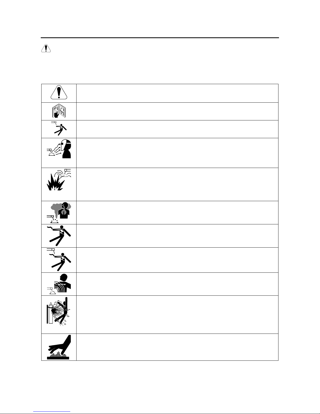
WARNING: This symbol indicates that instructions must be followed to avoid serious personal
injury, loss of life, or damage to this equipment. Protect yourself and others from possible serious
injury or death.
READ AND UNDERSTAND INSTRUCTIONS: Read and understand this manual before
operating this equipment. Arc welding can be hazardous. Failure to follow the instructions in this
manual could cause serious personal injury, loss of life, or damage to this equipment.
ELECTRIC SHOCK CAN KILL: Welding equipment generates high voltages. Do not touch the
electrode, work clamp, or connected work pieces when this equipment is on. Insulate yourself
from the electrode, work clamp and connected work pieces.
ARC RAYS CAN BURN: Use a shield with the proper filter and cover plates to protect your eyes
from sparks and the rays of the arc when welding or observing. Use suitable clothing made from
durable flame-resistant material to protect you skin and that of your helpers. Protect other nearby
personnel with suitable, non-flammable screening and warn them not to watch the arc nor expose
themselves to the arc.
WELDING SPARKS CAN CAUSE FIRE OR EXPLOSION: Remove fire hazards from the welding
area and have a fire extinguisher readily available. Welding sparks and hot materials from the
welding process can easily go through small cracks and openings to adjacent areas. Do not weld
on any tanks, drums, containers, or material until the proper steps have been taken to insure that
no flammable or toxic vapors will be present. Never operate this equipment when flammable
gases, vapors or liquid combustibles are present.
FUMES AND GASES CAN BE DANGEROUS: Welding may produce fumes and gases
hazardous to health. Avoid breathing these fumes and gases. To avoid these dangers the
operator must use enough ventilation or exhaust to keep fumes and gases away from the
breathing zone.
ELECTRICALLY POWERED EQUIPMENT: Turn off input power using the disconnect switch at
the fuse box before working on this equipment. Ground this equipment in accordance with local
electrical regulations.
ELECTRICALLY POWERED EQUIPMENT: Regularly inspect the input, electrode, and work
clamp cables. If any insulation damage exists replace the cable immediately. Do not place the
electrode holder directly on the welding table or any other surface in contact with the work clamp
to avoid the risk of accidental arc ignition.
ELECTRIC AND MAGNETIC FIELDS MAY BE DANGEROUS: Electric current flowing through
any conductor creates electric and magnetic fields (EMF). EMF fields may interfere with some
pacemakers and welders having a pacemaker shall consult their physician before operating this
equipment.
CYLINDER MAY EXPLODE IF DAMAGED: Use only compressed gas cylinders containing the
correct shielding gas for the process used and properly operating regulators designed for the gas
and pressure used. Always keep cylinders in an upright position securely chained to a fixed
support. Do not move or transport gas cylinders with the protection cap removed. Do not allow
the electrode, electrode holder, work clamp or any other electrically live part to touch a gas
cylinder. Gas cylinders must be located away from areas where they may be subjected to
physical damage or the welding process including sparks and heat sources.
WELDED MATERIALS CAN BURN: Welding generates a large amount of heat. Hot surfaces
and materials in work area can cause serious burns. Use gloves and pliers when touching or
moving materials in the work area.
Page 7
5
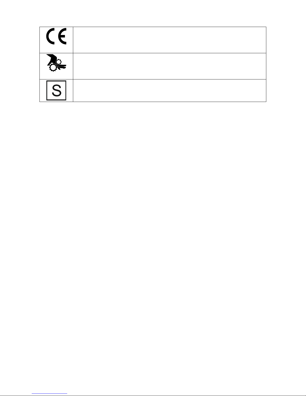
CE COMPLIANCE: This equipment complies with the European Community Directives.
MOVING PARTS ARE DANGEROUS: There are moving mechanical parts in this machine, which
can cause serious injury. Keep your hands, body and clothing away from those parts during
machine starting, operating and servicing.
SAFETY MARK: This equipment is suitable for supplying power for welding operations carried
out in an environment with increased hazard of electric shock.
The manufacturer reserves the right to make changes and/or improvements in design without upgrade at the same time
the operator’s manual.
Page 8
6
Installation and Operator Instructions
Read this entire section before installation or operation of the machine.
Location and Environment
This machine will operate in harsh environments. However, it is important that simple preventative measures are
followed to assure long life and reliable operation:
Do not place or operate this machine on a surface with an incline greater than 15° from horizontal.
Do not use this machine for pipe thawing.
This machine must be located where there is free circulation of clean air without restrictions for air movement to
and from the air vents. Do not cover the machine with paper, cloth or rags when switched on.
Dirt and dust that can be drawn into the machine should be kept to a minimum.
This machine has a protection rating of IP23. Keep it dry when possible and do not place it on wet ground or in
puddles.
Locate the machine away from radio controlled machinery. Normal operation may adversely affect the operation
of nearby radio controlled machinery, which may result in injury or equipment damage. Read the section on
electromagnetic compatibility in this manual.
Do not operate in areas with an ambient temperature greater than 40°C.
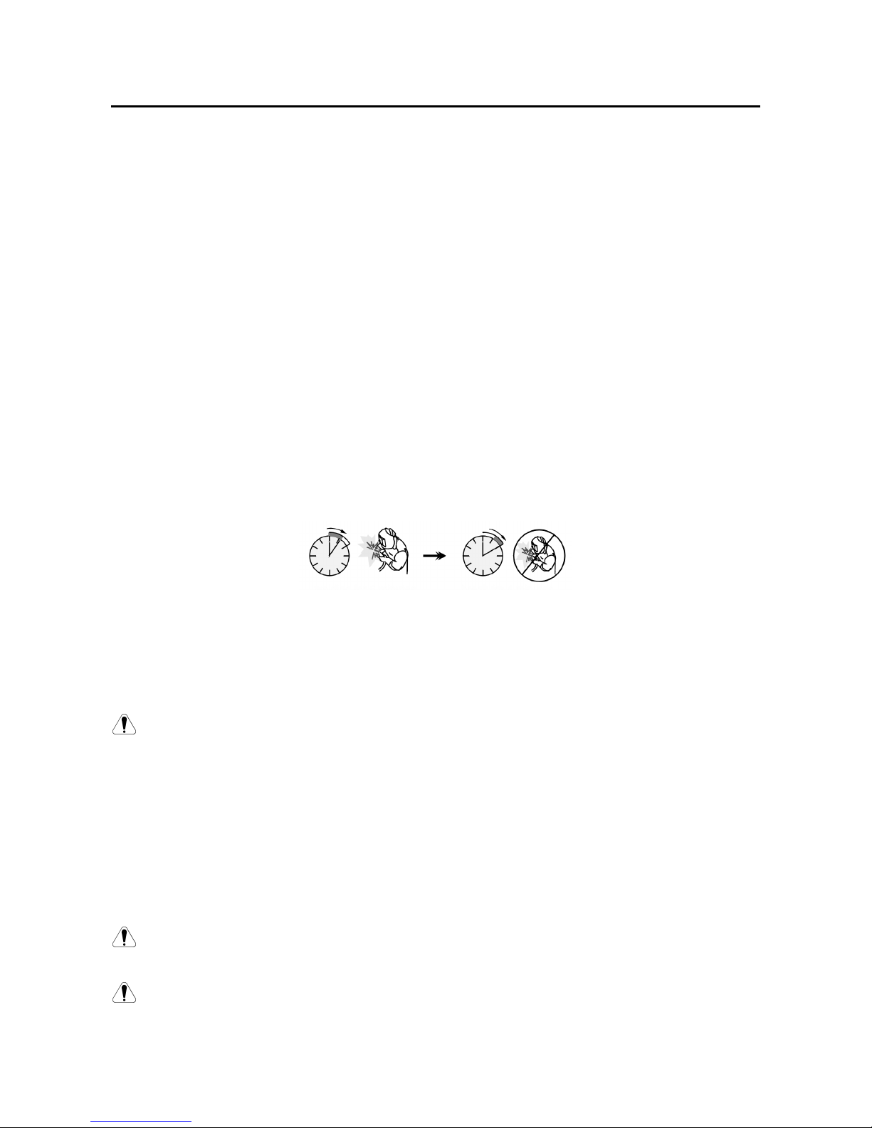
Duty cycle and Overheating
The duty cycle of a welding machine is the percentage of time in a 10 minute cycle at which the welder can operate the
machine at rated welding current. Interpretation is shown below:
Example: 60% duty cycle:
Welding for 6 minutes. Break for 4 minutes.
Excessive extension of the duty cycle will cause the thermal protection circuit to activate.
Input Supply Connection
Warning! Only a qualified electrician can connect the welding machine to the supply network. Installation
had to be made in accordance with the appropriate National Electrical Code and local regulations.
Check the input voltage, phase and frequency supplied to this machine before turning it on. Verify the connection of
ground wires from the machine to the input source. The welding machine MAGPOWER 2100 i must be connected to
a correctly installed plug-in socket with an earth pin.
Input voltage is 1x230V, 50/60Hz. For more information about input supply refer to the technical specification section of
this manual and to the rating plate of the machine.
Make sure that the amount of mains power available from the input supply is adequate for normal operation of the
machine. The necessary delayed fuse (or circuit breaker with "D" characteristic) and cable sizes are indicated in the
technical specification section of this manual.
Warning! The welding machine can be supplied from an engine driven generator of output power at least
30% larger than input power of the welding machine. Engine driven generator must have voltage
stabilizator. Otherwise, may cause a damage. See "Technical Specifications" chapter.
Warning! When powering welder from a generator be sure to turn off welder first, before generator is shut
down, in order to prevent damage to welder!
Page 9
7
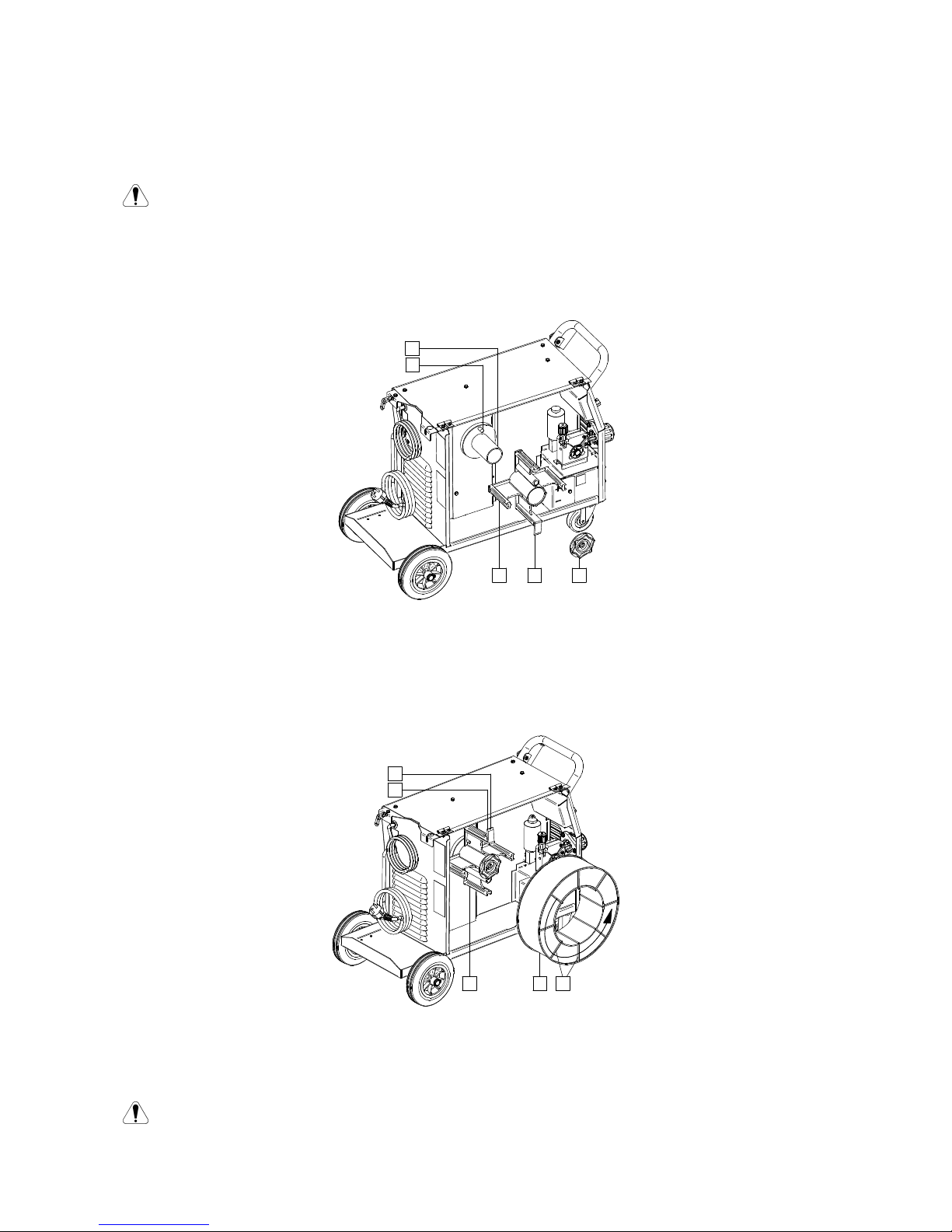
Wire Spool Loading
Wire spool type S300 and BS300 can be installed on the wire spool support without adapter. Wire spool type S200,
B300 or Readi-Reel® can be installed, but the applicable adapter must be purchased. The applicable adapter can be
purchased separately(see "Accessories" chapter).
Warning! Turn the input power OFF at the welding power source before installation or changing a wire
spool.
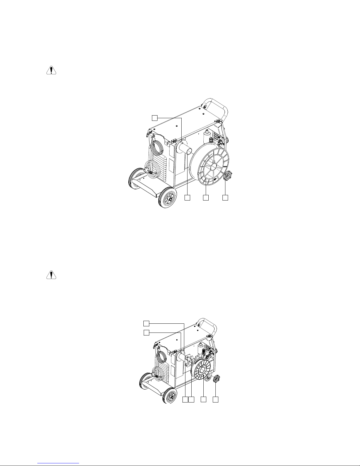
Wire Spool Type S300 or BS300 Loading
19
22
20
21
Turn the input power OFF.
Open the side panel.
Unscrew the Locking Nut [19] and remove it from the spindle [21].
Place the spool type S300 or BS300 [20] on the Spindle [21] making certain the Spindle Brake Pin [22] is put in
the hole in back side of spool type S300 or SB300.
Warning! Position the spool type S300 or SB300 so that it will rotate in a direction when feeding so as to be
de-reeled from bottom of the spool.
Re-install the locking nut [19]. Make sure that the locking nut is tightened.
Wire Spool Type S200 Loading
19
25
22
21
2423
Turn the input power OFF.
Open the side panel.
Unscrew the Locking Nut [19] and remove it from the spindle [21].
Page 10
8
Place the adapter of spool type S200 [23] on the spindle [21] making certain the spindle brake pin [22] is put in
the hole in back side of the adapter [23]. The adapter of spool type S200 can be purchased separately (see
"Accessories" chapter).
Place the spool type S200 [25] on the spindle [21] making certain that the adapter brake pin [24] is put in the hole
in the back side of the spool.
Warning! Position the spool type S200 so that it will rotate in a direction when feeding so as to be dereeled from bottom of the spool.
Re-install the locking nut [19]. Make sure that the locking nut is tightened.
Wire Spool Type B300 Loading
19
22
21
26 27
Turn the input power OFF.
Open the side panel.
Unscrew the Locking Nut [19] and remove it from the spindle [21].
Place the adapter of spool type B300 [26] on the spindle [21].Make certain that the spindle brake pin [22] is put in
the hole in the back side of the adapter [26]. The adapter of spool type B300 can be purchased separately (see
"Accessories" chapter).
Re-install the locking nut [19]. Make sure that the locking nut is tightened.
26
27
28
29 30
Rotate the spindle and adapter so the retaining spring [27] is at the 12 o'clock position.
Place the spool type B300 [29] on the adapter [26]. Set one of the B300 inside cage wires [30] on the slot [28] in
the retaining spring tab [27] and slide the spool onto the adapter.
Warning! Position the spool type B300 so that it will rotate in a direction when feeding so as to be dereeled from bottom of the spool.
Page 11

9
29
27
Wire Spool Type Readi-Reel® Loading
19
31
22
21
34
33
32 30
Turn the input power OFF.
Open the spool wire case.
Unscrew the locking nut [19] and remove it from the spindle [21].
Place the adapter of spool type Readi-Reel® [31] on the spindle [21].Make certain that the spindle brake pin [22] is
put in the hole in the back side of the adapter [31]. The adapter of spool type Readi-Reel® can be purchased
separately (see "Accessories" chapter).
Re-install the locking nut [19]. Make sure that the locking nut is tightened.
Rotate the spindle and adapter so the retaining spring [32] is at the 12 o'clock position.
Place the spool type Readi-Reel® [34] on the adapter [31]. Set one of the Readi-Reel® inside cage wires [30] on
the slot [33] in the retaining spring tab [32].
Warning! Position the spool type Readi-Reel® so that it will rotate in a direction when feeding so as to be
de-reeled from bottom of the spool.
Loading the Electrode Wire
Turn the input power OFF.
Open the side panel of the machine.
Unscrew the locking nut of the sleeve.
Load the spool with the wire [15] on the sleeve such that the spool turns anticlockwise when the wire [14] is fed
into the wire feeder.
Make sure that the spool locating pin goes into the fitting hole on the spool.
Screw in the looking nut of the sleeve.
Put on the wire roll using the correct groove corresponding to the wire diameter.
Free the end of the wire and cut off the bent end making sure it has no burr.
Warning! Sharp end of the wire can hurt.
Page 12

10
Rotate the wire spool anticlockwise and thread the end of the wire into the wire feeder as far as the Euro socket.
Adjust force of pressure roll of the wire feeder properly.
Changing Driving Rolls
Warning! Turn the input power OFF at the welding power source before installation or changing drive rolls
and/or guides.
MAGPOWER 2100 i is equipped with drive roll V0.8/V1.0 for steel wire. For others wire sizes, is available the proper
drive rolls kit (see "Accessories" chapter) and follow instructions:
Turn the input power OFF.
Release the pressure roll lever [37].
Unscrew the fastening cap [38].
Change the drive roll [40] with the compatible ones corresponding to the used wire.
Warning! Be sure that the gun liner and contact tip are also sized to match the selected wire size.
Screw fastening cap [38].
Manually feed the wire from the wire reel, the wire through the guide tubes, over the roller and guide tube of Euro
Socket into liner of gun.
Lock the pressure roll lever [37].
39 38
37
Adjusting of Force of Pressure Roll Force
The pressure arm controls the amount of force the drive rolls exert on the wire.
Pressure force is adjusted by turning the adjustment nut clockwise to increase force, counterclockwise to decrease
force. Proper adjustment of pressure arm gives the best welding performance.
Warning: If the roll pressure is too low the roll will slide on the wire. If the roll pressure is set too high the
wire may be deformed, which will cause feeding problems in the welding gun. The pressure force should
be set properly. Decrease the pressure force slowly until the wire just begins to slide on the drive roll and
then increase the force slightly by turning of the adjustment nut by one turn.
Page 13

11
Inserting Electrode Wire into Welding Gun
Warning: Take precaution to keep eyes and hands away from the end of the gun while the wire is being
come out of the threated end.
Turn the input power OFF.
Depending on welding process, connect the proper gun to the euro socket, the rated parameters of the gun and of
the welding machine should be matched.
Remote the nozzle from the gun and contact tip or protection cap and contact tip. Next, straighten the gun out flat.
Insert the wire through the guide tube, over the roller and through the guide tube of Euro Socket into liner of gun.
The wire can be pushed into the liner manually for a few centimeters, and should feed easily and without any
force.
Warning: If force is required it is likely that the wire has missed the liner of gun.
Turn the input power ON.
Depress the gun trigger to feed the wire through the gun liner until the wire comes out of the threaded end.
When trigger is released spool of wire should not unwind.
Adjust wire spool brake accordingly.
Turn the welding machine off.
Install a proper contact tip.
Depending on the welding process and the type of the gun, install the nozzle (GMAW process) or protection cap
(FCAW-SS process).
Uwaga: Take precaution to keep eyes and hands away from the end of the gun while the wire is being
come out of the threated end.
Adjustments of Brake Torque of Sleeve
To avoid spontaneous unrolling of the welding wire the sleeve is fitted with a brake. Adjustment is carried by rotation of
its screw M10, which is placed inside of the sleeve frame after unscrewing the fastening cap of the sleeve.
36
35
19
[19] Fastening cap.
[35] Adjusting screw M10.
[36] Pressing spring.
Turning the screw M10 clockwise increases the spring tension and you can increase the brake torque.
Turning the screw M10 anticlockwise decreases the spring tension and you can decrease the brake torque.
After finishing of adjustment, you should screw in the fastening cap again.
Gas Connection
Connect the gas hose to the Gas Connector located on the rear panel of the machine.
Put the gas cylinder on the machine shelf and secure it with the chain.
A gas cylinder must be installed with a proper flow regulator.
Once a gas cylinder with a flow regulator has been securely installed, connect the gas hose to the regulator using
the hose clamp.
Page 14

12
Warning: The welding machine supports all suitable shielding gases at a maximum pressure of 5,0 bar.
Warning: Always fasten gas cylinder properly in vertical position in a special holder on the wall or on a
carriage. Remember to close gas cylinder valve after having finished welding. Gas cylinder can be fasten
on the machine’s shelf, but the height of gas cylinder doesn’t have to be higher than 43in/1,1m. See the
Figure 19. The gas cylinder which is fastened on the machine’s shelf has to be secured by attaching it to
the machine using the chain.
Welding GMAW, FCAW-SS Process
MAGPOWER 2100 i can be used to welding GMAW and FCAW-SS process.
MAGPOWER 2100 i includes the gun necessary for GMAW.
Procedure of begin welding of GMAW or FCAW-SS process:
Place the machine conveniently near the work area in a location to minimize exposure to weld spatter and to
avoid sharp bends in the gun cable.
Determine the wire polarity for the wire to be used. Consult the wire data for this information.
Connect output the gas-cooled gun to GMAW / FCAW-SS process to Euro Socket [8].
Depending on the using wire, connect the work lead to output socket [9] or [10]. See [18] point – terminal block of
changing polarity.
Connect the work lead to the welding piece with the work clamp.
Install the proper wire.
Install the proper drive roll.
Manually push the wire into the gun’s liner.
Make a sure, if it is needed (GMAW process), that the gas shield has been connected.
Turn the machine on.
Insert the wire into the welding gun.
Warning: Keep the gun cable as straight as possible when loading electrode through cable.
Warning: Never use defected gun.
Close the wire drive door.
Set the welding parameters.
The welding machine is now ready to weld.
Warning: The wire drive door has to be completely closed during welding.
By applying the principle of occupational health and safety at welding, welding can be begun.
In manual mode can be set:
• The welding load voltage.
• WFS (wire feed speed).
• Inductance.
Page 15

13
Welding SMAW (MMA) Process)
MAGPOWER 2100 i does not include the electrode holder with lead necessary for SMAW welding, but the one can be
purchased separately. See "Accessories" chapter.
Procedure of begin welding of SMAW process:
Determine the electrode polarity for the electrode to be used. Consult the electrode data for this information.
Depending on the polarity of using electrode, connect the work lead and the electrode holder with lead to output
socket or and lock them.
Output socket
POLARITY
DC (+)
The electrode
holder with lead to
SMAW
[9]
Work lead
[10]
DC (-)
The electrode
holder with lead to
SMAW
[10]
Work lead
[9]
Connect the work lead to the welding piece with the work clamp.
Install the proper electrode in the electrode holder.
Turn the welding machine on.
Set the welding parameters.
The welding machine is now ready to weld.
By applying the principle of occupational health and safety at welding, welding can be begun.
User can set functions:
• The welding current
• HOT START
• ARC FORCE
Maintenance
Warning: For any repair operations, modifications or maintenances, it is recommended to contact the
nearest Technical Service Center or Lincoln Electric Bester Sp. z o. o. Repairs and modifications
performed by unauthorized service or personnel will cause, that the manufacturer’s warranty will become
null and void.
Any noticeable damage should be reported immediately and repaired.
Routine maintenance
Check condition of insulation and connections of the work leads and insulation of power lead. If any insulation
damage exists replace the lead immediately.
Remove the spatters from the welding gun nozzle. Spatters could interfere with the shielding gas flow to the arc.
Check the welding gun condition: replace it, if necessary.
Check condition and operation of the cooling fan. Keep clean its airflow slots.
Periodic maintenance
Perform the routine maintenance and, in addition:
Keep the machine clean. Using a dry (and low pressure) airflow, remove the dust from the external case and from
the cabinet inside.
If it is required, clean and tighten all weld terminals.
Page 16

14
The frequency of the maintenance operations may vary in accordance with the working environment where the machine
is placed.
Warning: Do not touch electrically live parts
Warning: Before the case of welding machine will be removed, the welding machine had to be turned off
and the power lead had to be disconnected from mains socket.
Warning: Mains supply network must be disconnected from the machine before each maintenance and
service. After each repair, perform proper tests to ensure safety.
Page 17

15
Controls and Operational Features
1. Power Switch ON/OFF (I/O): Controls the input power to the machine. Be sure the power source is connected to the
mains supply before turning power on ("I"). After input power is connected and the power switch is turned on, the
indicator will light up to indicate the machine is ready to weld.
2. Process Welding’s Switch:
GMAW (MIG/MAG) process
Warning: Can be used to FCAW-
SS process.
SMAW (MMA) process
Warning: When the machine is switched again on, last welding process will be recalled.
Warning: If the push-button is pushed in GMAW process in, the output terminals will lived.
Warning: During SMAW process, the output terminals are still lived.
3. Current Control: Depending on welding process, this knob controls:
SMAW
process
The welding current is set by this knob [6] (also during
welding). Scale on the panel is for welding 1.0 mm wire in
82Ar/18C02 gas shield.
Page 18

16
4. WFS/Hot Start Control: Depending on welding process, this knob controls:
GMAW
process
Wire feed speed WFS: Value in percentage of nominal
value wire feed speed.
SMAW
process
HOT START: Procentowa regulacja wzrostu nominalnej
wartości prądu podczas zajarzania elektrody, powoduje
chwilowy wzrost prądu wyjściowego i ułatwia zapłon
elektrody.
5. Control: Depending on welding process, this knob controls:
GMAW
process
Inductance: Arc control is controlled by this knob. If the
value is higher, the arc will be softer and during welding is
less spatters.
SMAW
process
ARC FORCE: The output current is temporarily increased
to clear short circuit connections between the electrode and
the workpiece.
6. LED Indicator Power switch: This LED lights up when the welding machine is ON and is ready to work.
7. Thermal Overload Indicator: It indicates that the machine is overloaded or that the cooling is not sufficient.
Warning: If the welding current exceed 200 A, output power will be turned off after 5 seconds. It will be
indicated by Thermal Overload Indicator. Output power will be turned on again after 3 minutes.
8. EURO Socket: For connecting a welding gun (for GMAW / FCAW-SS process).
9. Positive Output Socket for the Welding Circuit: For connecting an electrode holder with lead / work lead.
10. Negative Output Socket for the Welding Circuit: For connecting an electrode holder with lead / work lead.
11. Gas Connector: Connection for gas line.
12. Power Lead with Plug (3m): Power lead with plug is a standard equipment. Connect the power lead with plug to the
main supply before turning power on.
12
11
Page 19

17
13
1415
17
18
16
13. Wire Drive (for GMAW, FCAW-SS process): 2-Roll wire drive.
14. Welding Wire (for GMAW / FCAW-SS).
15. Spooled Wire (for GMAW / FCAW-SS): The machine does not include a spooled wire.
16. Wire Spool Support: Maximum 15kg spools. Accepts plastic, steel and fiber spools onto 51mm spindle. Also accepts
Readi-Reel® type spools onto included spindle adapter.
17. Shield of Changing Polarity.
18. Terminal Block of Changing Polarity (for GMAW / FCAW-SS process): This terminal block enables to set the welding
polarity (+ ; -), which will be given at the welding holder.
Warning: Positive (+) polarity is set at the factory.
Warning: Before welding check the polarity for using electrodes and wires.
If the welding polarity has to be changed, user should:
Switch off the machine.
Determine the wire polarity for the wire to be used. Consult the electrode data for this information.
Take off the terminal block’s shield [17].
The tip of the wire on the terminal block [18] and work lead fix as is shown in the Table 1 or the Table 2.
Put on the terminal block’s shield [17].
Warning: The machine must be used with the door completely closed during welding.
Warning: Not use handle to move the machine during work.
Page 20

18
Table 1.
Positive polarity
(factory setting)
Table 2.
Negative polarity
Page 21

19
Electromagnetic Compatibility (EMC)
This machine has been designed in accordance with all relevant directives and standards. However, it may still
generate electromagnetic disturbances that can affect other systems like telecommunications (telephone, radio, and
television) or other safety systems. These disturbances can cause safety problems in the affected systems. Read and
understand this section to eliminate or reduce the amount of electromagnetic disturbance generated by this machine.
This machine has been designed to operate in an industrial area. To operate in a domestic area it is
necessary to observe particular precautions to eliminate possible electromagnetic disturbances. The
operator must install and operate this equipment as described in this manual. If any electromagnetic
disturbances are detected the operator must put in place corrective actions to eliminate these
disturbances with, if necessary, assistance from Lincoln Electric.
Before installing the machine, the operator must check the work area for any devices that may malfunction because of
electromagnetic disturbances. Consider the following: Input and output cables, control cables, and telephone cables
that are in or adjacent to the work area and the machine. Radio and/or television transmitters and receivers. Computers
or computer controlled equipment. Safety and control equipment for industrial processes. Equipment for calibration and
measurement. Personal medical devices like pacemakers and hearing aids. Check the electromagnetic immunity for
equipment operating in or near the work area. The operator must be sure that all equipment in the area is compatible.
This may require additional protection measures. The dimensions of the work area to consider will depend on the
construction of the area and other activities that are taking place.
Consider the following guidelines to reduce electromagnetic emissions from the machine:
Connect the machine to the input supply according to this manual. If disturbances occur if may be necessary to take
additional precautions such as filtering the input supply. The output cables should be kept as short as possible and
should be positioned together. If possible connect the work piece to ground in order to reduce the electromagnetic
emissions. The operator must check that connecting the work piece to ground does not cause problems or unsafe
operating conditions for personnel and equipment. Shielding of cables in the work area can reduce electromagnetic
emissions. This may be necessary for special applications.
WARNING
The Class A equipment is not intended for use in residential locations where the electrical power is provided by
the public low-voltage supply system. There can be potential difficulties in ensuring electromagnetic
compatibility in those locations, due to conducted as well as radio-frequency disturbances.
WARNING: This equipment does not comply with IEC 61000-3-12. If it is connected to a public low voltage
system, it is the responsibility of the installer or user of the equipment to ensure, by consultation with the
distribution network operator, that the equipment may be connected.
Page 22

20
Technical Specifications
NAME
INDEX
MAGPOWER 2100 i B18252-1
INPUT
Input Voltage U
EMC Class
Frequency
230V ± 10%
1 – phase
A 50 / 60Hz
Input Power at Rated Cycle
Input Amperes I
PF
7.6 kVA @ 20 % Duty Cycle (40°C) 33 A 0.66
RATED OUTPUT
Open Circuit Voltage
Duty Cycle 40°C
(based on a 10 min.
period)
Output Current Output Voltage
GMAW
49 Vdc
100 80 A 18 Vdc
20 180 A 23 Vdc
FCAW
-SS
49 Vdc
100 80 A 18 Vdc
20 180 A 23 Vdc
SMAW
49 Vdc
100 80 A 23.2 Vdc
20 160 A 26.4 Vdc
WELDING CURRENT RANGE
GMAW
FCAW
-SS
SMAW
20A – 180 A 20A – 180 A 20 – 160 A
RECOMMENDED FUSE SIZES AND INPUT CABLE
Fuse or Circuit Breaker Size Power Lead
230 V
D 25 A 3 Conductor, 1.5mm2
DIMENSION
Weight
Height
Width
Length
27.5 kg 600 mm 280mm 800 mm
WIRE FEED SPEED RANGE / WIRE DIAMETER
WFS range
Drive roll
Drive roll diameter
Solid wires
Cored wires
1m/min ÷ 13m/min 2 Ø37 0.6 ÷ 1.0 0.9 ÷ 1.1
Protection Rating
Operating Temperature
Storage Temperature
IP23 od -10 ºC do +40 ºC od -25 ºC do +55 ºC
Page 23

21
Accessories
K10429-15-3M Welding gun LGS150 G-3.0 GMAW - 3m
K10429-15-4M Welding gun LGS150 G-4.0 GMAW - 4m
K10429-15-5M Welding gun LGS150 G-5.0 GMAW - 5m
KP10461-1 Gas nozzles Ø12mm
KP10440-06 Contact tip M6x25mm ECu 0.6mm
KP10440-08 Contact tip M6x25mm ECu 0.8mm
KP10440-09 Contact tip M6x25mm ECu 0.9mm
KP10440-10 Contact tip M6x25mm ECu 1.0mm
KP10468 Dysza ochronna do procesu FCAW-SS
E/H-200A-25-3M SMAW Electrode lead - 3m
GRD-200A-35-5M Work return lead (masowy) - 5m
KIT-200A-25-3M
SMAW Lead Kit:
• Electrode lead - 3m
• Work return lead - 3m
R-1019-125-1/08 Spool adapter type S200
K10158-1 Spool adapter type B300
K363P
Spool adapter type Readi-Reel®
Drive Rolls to 2 driven rolls
Druty lite:
KP14016-0.8 V0.6 / V0.8
KP14016-1.0 V0.8 / V1.0
Druty proszkowe:
KP14016-1.1R VK0.9 / VK1.1
Page 24

22
Spare Parts
1
3 2 3 9 7
4
5
26 25
17
16
15
19
18
2120
24
22
23
30
34
32
33
31
11
12
13
14
2735
40
36
10
6
8
28
29
33
37
38
39
41
47
41
41
42
43
44
45
46
Page 25

23
B Number Product name CODE
B18252-1 MAGPOWER 2100 i 1190 A
1 BASE R-1019-376-1/08R 1
2 BRACKET R-3019-337-1/08R 1
3 REAR WHEELS 1029-660-007R 2
4 BRACKET R-3019-356-1/08R 1
5 TERMINAL BLOCK 1361-599-328R 1
6 INSULATOR RINGS 1361-599-670R 2
7 COVER R-3019-346-1/08R 1
8 STICKER 2719-107-732R 1
9 COVER R-1019-380-1/08R 1
10 FRONT WHEELS 1029-660-004R 2
11 DIVIDER R-3019-334-1/08R 1
12 BRACKET R-1019-377-1/08R 1
13 REEL HUB STANDARD 0744-000-192R 1
14 PLASTIC NUT B11035-1 1
15 FRONT PANEL R-3019-332-1/08R 1
16 SOCKETS X2, X3 C-2986-001-2R 2
17 EURO SLEEVE 1361-599-708R 1
18 CONTROL 9ST13639-3 1
19 STICKER (FRONT PANEL) R-0010-562-1R 1
20 RUBBER BUTTON 1373-182-005R 1
21 GUN HOLDER R-3019-211-1/08R 1
22 SWITCH 1115-270-019R 1
23 BLACK FRAME SHIELD 1115-299-073R 1
24 CONTROLS 9SS18425-1 2
25 P.C. BOARD Y031-1R 1
26 COVER R-1019-381-1/08R 1
27 REAR PANEL R-1012-634-1/08R 1
28 CABLE RELIEF 1361-599-399R 1
29 CLAMP 1361-599-398R 1
30 COVER R-1019-433-1R 1
31 HINGLE WITH AXLE D-3574-011-4/02R 1
32 HINGLE WITH AXLE D-3574-011-3/02R 1
33 HINGLES D-3574-007-1/33R 2
34 STICKER 2719-107-728R 1
35 WIRE DRIVE DOOR R-1019-434-1R 1
36 LOCK 0654-610-004R 1
37 STICKER (GAS) 2719-107-733R 1
38 POWER LEAD (3M) R-5041-331-1R 1
39 STICKER (HEIGHT OF GAS CYLINDER) R-7040-228-3R 1
40 STICKER (WIRING DIAGRAM – NOT SHOWN) R-0010-563-1R 1
41 RUBBER BUSH 1373-182-002R 3
42 GAS SOLENOID 0972-423-040R 1
43 FAN BAFFLE R-1019-378-1/08R 1
44 FAN 0873-100-034R 1
45 DEFLECTOR R-0010-458-2R 1
46 P.C. BOARD R-6042-069-1R 1
47 CHOKE L1 R-4034-148-1R 1
Page 26

24
51
545352
49
48
50 5556
WIRE DRIVE ASSEMBLY 0744-000-269R 1
48 MOTOR 0744-000-270R 1
49 FIXING ARM COMPL. 0646-233-015R 1
50 PRESSURE ARM COMPLETE 0744-000-249R 1
51 FEED PLATE 0744-000-271R 1
52 WASHER 0744-000-272R 1
53 ADAPTER 0744-000-250R 1
54 FIXING CAP 0744-000-251R 1
55 EURO SOCKET X3 R-8040-362-1R 1
56 OUTLET GUIDE R-2010-006-4R 1
Items not shown on figures:
57
HARNESS (PRIMARY) R-5041-337-1R
1
58
WIRES R-5041-338-1R
2
59
WIRE R-5041-339-1R
1
60
HARNESS (SECONDARY) R-5041-341-1R
1
Page 27

25
Electrical Schematic
PE
109
110
5 2
3
1
6
4
210
213
LIFT PLATE
R-5041-338-1
R-5041-338-1
R-5041-338-1
R-5041-339-1
R-5041-338-1
POLARITY
CHANGE
OUTPUT
CHOKE
MAIN
SWITCH
MAIN CORD
CURRENT
SENSE
DL-1
X2
X3
X4
1 3
278
-
+
262
1 2
263
X4
VALVE
MOTOR
507 (LED_MODE_MMA)
7
Y031-1
PANEL BOARD
508 (LED_MODE_MIG)8515 (SWITCH_MIG/MMA)
506 (+5V)
15
6
502 (3V3_A)
501 (GND_A)
503 (VOLT_POT)
511 (SPEED_POT)
504 (INDUCTANCE)
4
516 (LED ON-OFF)
512 (LED_THERM)
+
Th
R-6042-069-1R
MAIN BOARD
1615141312
10
1 9
21134568
7
X3
L1
X1
M2
BLACK
RED
277
2
4
X1
T5-4
T5-2T5-1
12
X2
PE
X5
105
106
103
+
230V AC
50/60 Hz
3
11
2
1
16
12
T5
T5-3
4
5
1
2
S1
102
K1
M1
L
N
L
N
PE
Page 28

26
WEEE
1
3 2 3 8 7
4
5
25 24
17
16
15
18
2019
23
21
22
29
31
32
30
11
12
13
2635
36
10
6
27
28
32
9
14
37
42
48
42
42
43
44
45
46
47
Page 29

27
Recycle ST
Fe
Al
Cu
Brass
Boards
Plastics
Liquid Cristal
External
Electric Cables
Capacitors
Description
Ref.
BASE 1 X
REAR PANEL 26 X
FRONT PANEL 15 X
BAFFLE 11, 12, 44
COVER 7, 8, 25, 29 X
LOCK 36 X
WIRE DRIVE DOOR 35 X
FAN 45 X X
HINGLE 30, 31, 32 X
P.C. BOARDS 24, 47 X
WIRE REEL SPINDLE 13 X X
BRACKET 2, 4 X
EURO SOCKET 14 X X
EURO SLEEVE 17 X
SOCKET 16 X X X
BLACK FLAME
SHIELD
22
X
CONTROL 18, 23 X
BUTTON 19 X
GAS SOLENOID 43 X X X
INSULATOR RING 6 X
WIRE FEEDER 9 X X X
TERMINAL BLOCK 5 X X
POWER LEAD 37 X X X
REAR WHEEL 3 X
FRONT WHEEL 10 X X
SWITCH 21 X X
GUN HOLDER 20 X
RUBBER CABLE
BUSH
42
X
CABLE RELIEF 27, 28 X
CHOKE 48 X X X
DEFLECTOR 46 X
Page 30

Page 31

Page 32

 Loading...