

Lincoln Electric 12879, APEX 3 Series, 70313, 12833 Operator's Manual
Operator’s Manual
APEX ® 3 SERIES MIG PENDANT
ORIGINAL INSTRUCTIONS
For use with machines having Code Numbers:
12879
Register your machine:
www.lincolnelectric.com/register
Authorized Service and Distributor Locator:
www.lincolnelectric.com/locator
Save for future reference
Date Purchased
Code: (ex: 10859)
Serial: (ex: U1060512345)
IM6122 | Issue D ate 02/19
© Lincoln Global, Inc. All Rights Reserved.
Need Help? In the USA and Canada, call
1.800.770.0063 to talk to a Service Representative.
Hours of Operation:
7:00 AM to 5:00 PM (PT) Mon. thru Fri.
After hours?
Use “Ask the Experts” at lincolnelectric.com
A Lincoln Service Representative will contact you
no later than the following business day.
For Service outside the USA and Canada, please call
1.619.628.1022 or e-mail us at:
orbitalsupport@lincolnelectric.com
c/o Balmes, 89 - 80 2
08008 Barcelona
a
SPAIN
APEX® 3 SERIES MIG PENDANT MANUAL
SAFETY
THANK YOU FOR SELECTING
A QUALITY PRODUCT BY
LINCOLN ELEC TRIC.
PLEASE EXAMINE CARTON AND EQUIPMENT FOR
DAMAGE IMMEDIATELY
When this equipment is shipped, title passes to the purchaser upon
receipt by the carrier. Consequently, Claims for material damaged in
shipment must be made by the purchaser against the transportation
company at the time the shipment is received.
SAFETY DEPENDS ON YOU
Lincoln arc welding and cutting equipment is designed and built with
safety in mind. However, your overall safety can be increased by
proper installation ... and thoughtful operation on your part.
DO NOT INSTALL, OPERATE OR REPAIR THIS EQUIPMENT
WITHOUT READING THIS MANUAL AND THE SAFETY PRECAUTIONS
CONTAINED THROUGHOUT. And, most importantly, think before you
act and be careful.
1WARNING
This statement appears where the information must be followed
exactly to avoid serious personal injury or loss of life.
CAUTION
This statement appears where the information must be followed to
avoid minor personal injury or damage to this equipment.
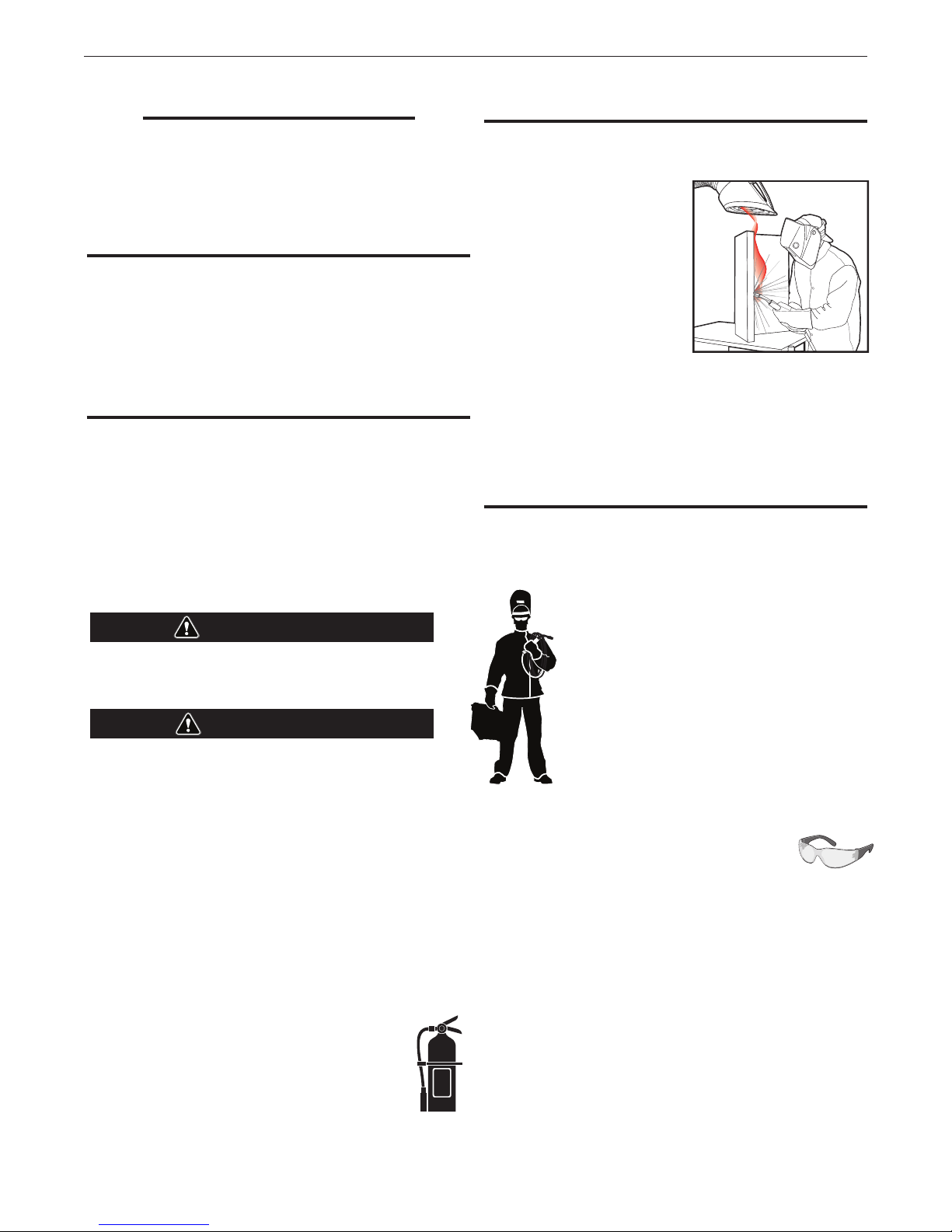
KEEP YOUR HEAD OUT OF THE FUMES.
DON’T get too close to the arc. Use corrective lenses if necessary to
stay a reasonable distance away from
the arc.
READ and obey the Material Safety
Data Sheet (MSDS) and the warning
label that appears on all containers of
welding materials.
USE ENOUGH VENTILATION or
exhaust at the arc, or both, to keep
the fumes and gases from your
breathing zone and the general area.
IN A LARGE ROOM OR OUTDOORS, natural ventilation may be
adequate if you keep your head out of the fumes (See below).
USE NATURAL DRAFTS or fans to keep the fumes away from your
face.
If you de velop unusual symptoms, see your supervisor. Perhaps the
welding atmosphere and ventilation system should be checked.
WEAR CORRECT EYE, EAR & BODY PROTECTION
PROTECT your eyes and face with welding helmet properly fitted and
with proper grade of filter plate (See ANSI Z49.1).
PROTECT your body from welding spatter and arc
flash with protective clothing including woolen
clothing, flame-proof apron and gloves, leather
leggings, and high boots.
PROTECT others from splatter, flash, and glare with
protective screens or barriers.
IN SOME AREAS, protection from noise may be
appropriate.
BE SURE protective equipment is in good condition.
Also, wear safety glasses in work area AT ALL
TIMES.
SPECIAL SITUATIONS
DO NOT WELD OR CUT containers or materials
which previously had been in contact with hazardous
substances unless they are properly cleaned. This is extremely
dangerous.
DO NOT WELD OR CUT painted or plated parts unless special
precautions with ventilation have been taken. They can release highly
toxic fumes or gases.
Additional precautionary measures
PROTECT compressed gas cylinders from excessive heat, mechanical
shocks, and arcs; fasten cylinders so they cannot fall.
BE SURE cylinders are never grounded or part of an electrical circuit.
REMOVE all potential fire hazards from welding area.
ALWAYS HAVE FIRE FIGHTING EQUIPMENT READY FOR IMMEDIATE
USE AND KNOW HOW TO USE IT.
2

APEX® 3 SERIES MIG PENDANT MANUAL
SECTION A:
WARNINGS
1.d. Keep all equipment safety guards, covers and
devices in position and in good repair.Keep
hands, hair, clothing and tools away from
V-belts, gears, fans and all other moving parts
when starting, operating or repairing equipment.
SAFETY
SAFETY
CALIFORNIA PROPOSITION 65 WARNINGS
Diesel Engines
Diesel engine exhaust and some of its constituents are known
to the State of California to cause cancer, birth defects, and other
reproductive harm.
Gasoline Engines
The engine exhaust from this product contains chemicals known
to the State of California to cause cancer, birth defects, or other reproductive harm.
ARC WELDING CAN BE HAZARDOUS. PROTECT
YOURSELF AND OTHERS FROM POSSIBLE SERIOUS
INJURY OR DEATH. KEEP CHILDREN AWAY.
PACEMAKER WEARERS SHOULD CONSULT WITH
THEIR DOCTOR BEFORE OPERATING.
Read and understand the following safety highlights. For additional
safety information, it is strongly recommended that you purchase a
copy of “Safety in Welding & Cutting - ANSI Standard Z49.1” from the
American Welding Society, P.O. Box 351040, Miami, Florida 33135
or CSA Standard W117.2-1974. A Free copy of “Arc Welding Safety”
booklet E205 is available from the Lincoln Electric Company, 22801
St. Clair Avenue, Cleveland, Ohio 44117-1199.
BE SURE THAT ALL INSTALLATION, OPERATION,
MAINTENANCE AND REPAIR PROCEDURES ARE
PERFORMED ONLY BY QUALIFIED INDIVIDUALS.
1.e. In some cases it may be necessary to remove safety guards
to perform required maintenance. Remove guards only when
necessary and replace them when the maintenance requiring
their removal is complete. Always use the greatest care when
working near moving parts.
1.f. Do not put your hands near the engine fan. Do not attempt to
override the governor or idler by pushing on the throttle control
rods while the engine is running.
1.g. To prevent accidentally starting gasoline engines while turning
the engine or welding generator during maintenance work,
disconnect the spark plug wires, distributor cap or magneto wire
as appropriate.
1.h. To avoid scalding, do not remove the radiator
pressure cap when the engine is hot.
ELECTRIC AND MAGNETIC FIELDS
MAY BE DANGEROUS
2.a. Electric current flowing through any conductor
causes localized Electric and Magnetic Fields
(EMF). Welding current creates EMF fields
around welding cables and welding machines
FOR ENGINE POWERED
EQUIPMENT.
1.a. Turn the engine off before troubleshooting and
maintenance work unless the maintenance
work requires it to be running.
1.b. Operate engines in open, well-ventilated areas
or vent the engine exhaust fumes outdoors.
1.c. Do not add the fuel near an open flame welding arc or when the
engine is running. Stop the engine and allow it to cool before
refueling to prevent spilled fuel from vaporizing
on contact with hot engine parts and igniting.
Do not spill fuel when filling tank. If fuel is
spilled, wipe it up and do not start engine until
fumes have been eliminated.
2.b. EMF fields may interfere with some pacemakers, and welders
having a pacemaker should consult their physician before
welding.
2.c. Exposure to EMF fields in welding may have other health effects
which are now not known.
2.d. All welders should use the following procedures in order to
minimize exposure to EMF fields from the welding circuit:
2.d.1. Route the electrode and work cables together - Secure
them with tape when possible.
2.d.2. Never coil the electrode lead around your body.
2.d.3. Do not place your body between the electrode and work
cables. If the electrode cable is on your right side, the
work cable should also be on your right side.
2.d.4. Connect the work cable to the workpiece as close as possible to the area being welded.
2.d.5. Do not work next to welding power source.
3
APEX® 3 SERIES MIG PENDANT MANUAL
SAFETY
SAFETY
ELECTRIC SHOCK
CAN KILL.
3.a. The electrode and work (or ground) circuits are
electrically “hot” when the welder is on. Do not
touch these “hot” parts with your bare skin or wet
clothing. Wear dry, hole-free gloves to insulate hands.
3.b. Insulate yourself from work and ground using dry insulation.
Make certain the insulation is large enough to cover your full area
of physical contact with work and ground.
In addition to the normal safety precautions, if
welding must be performed under electrically
hazardous conditions (in damp locations or while
wearing wet clothing; on metal structures such
as floors, gratings or scaffolds; when in cramped
positions such as sitting, kneeling or lying, if there
is a high risk of unavoidable or accidental contact
with the workpiece or ground) use the following
equipment:
• Semiautomatic DC Constant Voltage (Wire) Welder.
• DC Manual (Stick) Welder.
• AC Welder with Reduced Voltage Control.
3.c. In semiautomatic or automatic wire welding, the electrode,
electrode reel, welding head, nozzle or semiautomatic welding
gun are also electrically “hot”.
3.d. Always be sure the work cable makes a good electrical
connection with the metal being welded. The connection should
be as close as possible to the area being welded.
3.e. Ground the work or metal to be welded to a good electrical (earth)
ground.
3.f. Maintain the electrode holder, work clamp, welding cable and
welding machine in good, safe operating condition. Replace
damaged insulation.
3.g. Never dip the electrode in water for cooling.
3.h. Never simultaneously touch electrically “hot” parts of electrode
holders connected to two welders because voltage
the two can be the total of the open circuit voltage of both
welders.
3.i. When working above floor level, use a safety belt to protect
yourself from a fall should you get a shock.
3.j. Also see It ems 6.c. and 8.
between
ARC RAYS CAN BURN.
4.a. Use a shield with the proper filter and cover plates to protect
your eyes from sparks and the rays of the arc when welding or
observing open arc welding. Headshield and filter lens should
conform to ANSI Z87. I standards.
4.b. Use suitable clothing made from durable flame-resistant material
to protect your skin and that of your helpers from the arc rays.
4.c. Protect other nearby personnel with suitable, non-flammable
screening and/or warn them not to watch the arc nor expose
themselves to the arc rays or to hot spatter or metal.
FUMES AND GASES CAN
BE DANGEROUS.
5.a. Welding may produce fumes and gases
hazardous to health. Avoid breathing these
fumes and gases. When welding, keep your head out of the
fume. Use enough ventilation and/or exhaust at the arc to
keep fumes and gases away from the breathing zone. When
welding with electrodes which require special
ventilation such as stainless or hard facing (see
instructions on container or MSDS) or on lead or
cadmium plated steel and other metals or coatings
which produce highly toxic fumes, keep exposure
as low as possible and within applicable OSHA
PEL and ACGIH TLV limits using local exhaust
or mechanical ventilation. In confined spaces or
in some circumstances, outdoors, a respirator
may be required. Additional precautions are also
required when welding on galvanized steel.
5. b. The operation of welding fume control equipment is affected
by various factors including proper use and positioning of the
equipment, maintenance of the equipment and the specific
welding procedure and application involved. Worker exposure
level should be checked upon installation and periodically
thereafter to be certain it is within applicable OSHA PEL and
ACGIH TLV limits.
5.c. Do not weld in locations near chlorinated hydrocarbon vapors
coming from degreasing, cleaning or spraying operations. The
heat and rays of the arc can react with solvent vapors to form
phosgene, a highly toxic gas, and other irritating products.
5.d. Shielding gases used for arc welding can displace air and
injury or death. Always use enough ventilation, especially in
confined areas, to insure breathing air is safe.
cause
5.e. Read and understand the manufacturer’s instructions for this
equipment and the consumables to be used, including the
material safety data sheet (MSDS) and follow your employer’s
safety practices. MSDS forms are available from your welding
distributor or from the manufacturer.
5.f. Also see item 1.b.
4
APEX® 3 SERIES MIG PENDANT MANUAL
SAFETY
SAFETY
WELDING AND CUTTING
SPARKS CAN CAUSE
FIRE OR EXPLOSION.
6.a. Remove fire hazards from the welding area.
If this is not possible, cover them to prevent the welding sparks
from starting a fire. Remember that welding sparks and hot
materials from welding can easily go through small cracks and
openings to adjacent areas. Avoid welding near hydraulic lines.
Have a fire extinguisher readily available.
6.b. Where compressed gases are to be used at the job site, special
precautions should be used to prevent hazardous situations. Refer
to “Safety in Welding and Cutting” (ANSI Standard Z49.1) and the
operating information for the equipment being used.
6.c. When not welding, make certain no part of the electrode circuit
is touching the work or ground. Accidental contact can cause
overheating and create a fire hazard.
6.d. Do not heat, cut or weld tanks, drums or containers until the
proper steps have been taken to insure that such procedures will
not cause flammable or toxic vapors from substances inside. They
can cause an explosion even though they have been “cleaned”.
For information, purchase “Recommended Safe Practices for the
Preparation for Welding and Cutting of Containers and Piping That
Have Held Hazardous Substances”, AWS F4.1 from the American
Welding Society (see address above).
6.e. Vent hollow castings or containers before heating, cutting or
welding. They may explode.
6.f. Sparks and spatter are thrown from the welding arc. Wear oil free
protective garments such as leather gloves, heavy shirt, cuffless
trousers, high shoes and a cap over your hair. Wear ear plugs
when welding out of position or in confined places. Always wear
safety glasses with side shields when in a welding area.
CYLINDER MAY EXPLODE IF
DAMAGED.
7.a. Use only compressed gas cylinders containing
the correct shielding gas for the process used
and properly operating regulators designed for
the gas and pressure used. All hoses, fittings,
etc. should be suitable for the application and
maintained in good condition.
7.b. Always keep cylinders in an upright position securely chained to
an undercarriage or fixed support.
7.c. Cylinders should be located:
• Away from areas where they may be struck or subjected
to physical damage.
• A safe distance from arc welding or cutting operations
and any other source of heat, sparks, or flame.
7.d. Never allow the electrode, electrode holder or any other
electrically “hot” parts to touch a cylinder.
7.e. Keep your head and face away from the cylinder valve outlet
when opening the cylinder valve.
7.f. Valve protection caps should always be in place and hand tight
except when the cylinder is in use or connected for use.
7.g. Read and follow the instructions on compressed gas cylinders,
associated equipment, and CGA publication P-l, “Precautions for
Safe Handling of Compressed Gases in
from the Compressed Gas Association 1235 Jefferson Davis
Highway, Arlington, VA 22202.
Cylinders,” available
6.g. Connect the work cable to the work as close to the welding area
as practical. Work cables connected to the building framework
or other locations away from the welding area increase the
possibility of the welding current passing through lifting chains,
crane cables or other alternate circuits. This can create fire
hazards or overheat lifting chains or cables until they fail.
6.h. Also see item 1.c.
6.I. Read and follow NFPA 51B “ Standard for Fire Prevention During
Welding, Cutting and Other Hot Work”, available from NFPA, 1
Batterymarch Park, PO box 9101, Quincy, Ma 022690-9101.
6.j. Do not use a welding power source for pipe thawing.
FOR ELECTRICALLY
POWERED EQUIPMENT.
8.a. Turn off input power using the disconnect
switch at the fuse box before working on the
equipment.
8.b. Install equipment in accordance with the U.S. National Electrical
Code, all local codes and the manufacturer’s recommendations.
8.c. Ground the equipment in accordance with the U.S. National
Electrical Code and the manufacturer’s recommendations.
Refer to http://www.lincolnelectric.com/
safety for additional safety information.
5

APEX® 3 SERIES MIG PENDANT MANUAL
ELECTROMAGNETIC
COMPATIBILITY (EMC)
CONFORMANCE
Products displaying the CE mark are in conformity with European Community
Council Directive of 3 May 1989 on the approximation of the laws of the
Member States relating to electromagnetic compatibility (89/336/EEC). It
was manufactured in conformity with a national standard that implements a
harmonized standard: EN 60974-10
Electromagnetic Compatibility (EMC) Product Standard for Arc Welding
Equipment. It is for use with other Lincoln Electric equipment. It is designed
for industrial and professional use.
INTRODUCTION
All electrical equipment generates small amounts of electromagnetic
emission. Electrical emission may be transmitted through power lines or
radiated through space, similar to a radio transmitter. When emissions are
received by other equipment, electrical interference may result. Electrical
emissions may affect many kinds of electrical equipment; other nearby
welding equipment, radio and TV reception, numerical controlled machines,
telephone systems, computers, etc. Be aware that interference may result
and extra precautions may be required when a welding power source is used
in a domestic establishment.
INSTALLATION AND USE
The user is responsible for installing and using the welding equipment
according to the manufacturer’s instructions. If electromagnetic disturbances
are detected then it shall be the responsibility of the user of the welding
equipment to resolve the situation with the technical assistance of the
manufacturer. In some cases this remedial action may be as simple as
earthing (grounding) the welding circuit, see Note. In other cases it could
involve construction of an electromagnetic screen enclosing the power
source and the work complete with associated input filters. In all cases
electromagnetic disturbances must be reduced to the point where they are
no longer troublesome.
Note: The welding circuit may or may not be earthed for safety reasons according to national codes.
Changing the earthing arrangements should only be authorized by a person who is competent
to access whether the changes will increase the risk of injury, e.g., by allowing parallel welding
current return paths which may damage the earth circuits of other equipment.
ASSESSMENT OF AREA
Before installing welding equipment the user shall make an assessment of
potential electromagnetic problems in the surrounding area. The following
shall be taken into account:
a. other supply cables, control cables, signaling and telephone cables; above, below
and adjacent to the welding equipment;
b. radio and television transmitters and receivers;
c. computer and other control equipment;
d. safety critical equipment, e.g., guarding of industrial equipment;
e. the health of the people around, e.g., the use of pacemakers and hearing aids;
f. equipment used for calibration or measurement
g. the immunity of other equipment in the environment. The user shall ensure that
other equipment being used in the environment is compatible. This may require
additional protection measures;
h. the time of day that welding or other activities are to be carried out.
SAFETY
The size of the surrounding area to be considered will depend on the
structure of the building and other activities that are taking place. The
surrounding area may extend beyond the boundaries of the premises.
METHODS OF REDUCING EMISSIONS
Mains Supply
Welding equipment should be connected to the mains supply according
to the manufacturer’s recommendations. If interference occurs, it may be
necessary to take additional precautions such as filtering of the mains supply.
Consideration should be given to shielding the supply cable of permanently
installed welding equipment, in metallic conduit or equivalent. Shielding
should be electrically continuous throughout its length. The shielding should
be connected to the welding power source so that good electrical contact is
maintained between the conduit and the welding power source enclosure.
Maintenance of the Welding Equipment
The welding equipment should be routinely maintained according to the
manufacturer’s recommendations. All access and service doors and covers
should be closed and properly fastened when the welding equipment is
in operation. The welding equipment should not be modified in any way
except for those changes and adjustments covered in the manufacturers
instructions. In particular, the spark gaps of arc striking and stabilizing
devices should be adjusted and maintained according to the manufacturer’s
recommendations.
Welding Cables
The welding cables should be kept as short as possible and should be
positioned close together, running at or close to floor level.
Equipotential Bonding
Bonding of all metallic components in the welding installation and adjacent
to it should be considered. However, metallic components bonded to the
work piece will increase the risk that the operator could receive a shock by
touching these metallic components and the electrode at the same time. The
operator should be insulated from all such bonded metallic components.
Earthing of the Workpiece
Where the workpiece is not bonded to earth for electrical safety, not
connected to earth because of its size and position, e.g., ships hull or
building steelwork, a connection bonding the workpiece to earth may reduce
emissions in some, but not all instances. Care should be taken to prevent the
earthing of the work piece increasing the risk of injury to users, or damage
to other electrical equipment. Where necessary, the connection of the
workpiece to earth should be made by a direct connection to the work piece,
but in some countries where direct connection is not permitted, the bonding
should be achieved by suitable capacitance, selected according to national
regulations.
Screening and Shielding
Selective screening and shielding of other cables and equipment in the
surrounding area may alleviate problems of interference. Screening of the
entire welding installation may be considered for special applications.
1 Portions of the preceding text are contained in EN 60974-10: “Electromagnetic
Compatibility (EMC) product standard for arc welding equipment.”
6
APEX® 3 SERIES MIG PENDANT MANUAL
SAFETY
7

APEX® 3 SERIES MIG PENDANT MANUAL
TABLE OF CONTENTS
Safety ....................................................................................................................................................... 2
Symbols & Icons ................................................................................................................................... 10
Safety Precautions ............................................................................................................................... 11
Proper handling .................................................................................................................................11
Operation ............................................................................................................................................... 11
Explanation of Welding Terms ........................................................................................................... 11
System Start Up .............................................................................................................................. B-1
Startup Screen ......................................................................................................................... B-1
Pendant Operation ................................................................................................................... B-2
Button Actions .......................................................................................................................... B-2
Selection Buttons ..................................................................................................................... B-2
Navigation Controls .................................................................................................................. B-2
Menu Buttons ........................................................................................................................... B-3
Control Buttons ........................................................................................................................ B-3
Color Coding ............................................................................................................................ B-3
Fast Movement ......................................................................................................................... B-3
System Log In ................................................................................................................................. B-4
Fast Movement ......................................................................................................................... B-4
Log In Screen ........................................................................................................................... B-5
Idle Screen ...................................................................................................................................... B-6
Menu Option Variables ............................................................................................................. B-6
Idle Screen Buttons .................................................................................................................. B-7
Idle Screen Test/Weld Modes .........................................................................................................B-8
Weld Screen ............................................................................................................................. B-9
Weld Screen Buttons ................................................................................................................ B-9
Test Screen ............................................................................................................................... B-9
Test Screen Buttons ................................................................................................................. B-9
Jog Screen .................................................................................................................................... B-10
Jog Buttons ............................................................................................................................ B-11
Oscillation Screen ......................................................................................................................... B-12
Oscillation Buttons ................................................................................................................. B-13
Setup Menu .................................................................................................................................. B-14
Setup Screen Options ............................................................................................................ B-15
Track Setup ............................................................................................................................ B-15
Track Type .............................................................................................................................. B-15
Track Ring Size ....................................................................................................................... B-15
Pipe Size ................................................................................................................................. B-15
Heavy Wall Pipes .................................................................................................................... B-15
Positioner Setup ..................................................................................................................... B-15
Travel Setup Screen ............................................................................................................... B-16
Travel Pattern ........................................................................................................................ B-16
Process Setup Screen .................................................................................................................. B-17
Standard Process Options ..................................................................................................... B-17
Weave Process Options ......................................................................................................... B-17
Mode Select .................................................................................................................................. B-18
List Mode Select ..................................................................................................................... B-19
Advanced Process Setup ............................................................................................................ B-19
Advanced Options .................................................................................................................. B-19
Wave Controls ........................................................................................................................ B-19
Height/Sensitivity Recommendations .................................................................................... B-19
Start Settings ................................................................................................................................ B-20
End Settings .................................................................................................................................. B-20
8

APEX® 3 SERIES MIG PENDANT MANUAL
TABLE OF CONTENTS
GMAW/FCAW Timing Diagram ..................................................................................................... B-21
Service Menu ............................................................................................................................... B-22
Version .................................................................................................................................... B-22
Motion .................................................................................................................................... B-22
Faults ...................................................................................................................................... B-23
Settings .................................................................................................................................. B-23
Input Test ................................................................................................................................ B-23
How to Take a Snapshot ........................................................................................................ B-24
Users ............................................................................................................................................. B-25
Fast Movement ....................................................................................................................... B-25
Adding Users .......................................................................................................................... B-25
Deleting Users ........................................................................................................................ B-26
Changing User Access ........................................................................................................... B-27
Log Out ................................................................................................................................... B-27
Operator Log In ...................................................................................................................... B-27
Increments Settings ...................................................................................................................... B-28
Increment Options .................................................................................................................. B-28
Increment Reference .............................................................................................................. B-29
Programs ..................................................................................................................................... B-30
Fast Movement ....................................................................................................................... B-30
Saving an Independent Pass .................................................................................................. B-30
Saving a Program Base .......................................................................................................... B-31
Saving a Program Pass .......................................................................................................... B-31
Saving Program Updates ....................................................................................................... B-32
Hide Program Passes ............................................................................................................. B-33
Saving to a USB ..................................................................................................................... B-33
Copy to/from USB .................................................................................................................. B-33
Deleting a Program ................................................................................................................. B-34
Deleting a Program Base ........................................................................................................ B-34
Loading a Program ................................................................................................................. B-34
Overwriting a Program ........................................................................................................... B-35
Standard Piping Schedule Chart .......................................................................................................... 36
Wiring Diagram ...................................................................................................................................... 37
Parts ....................................................................................................................................................... 38
9
APEX® 3 SERIES MIG PENDANT MANUAL
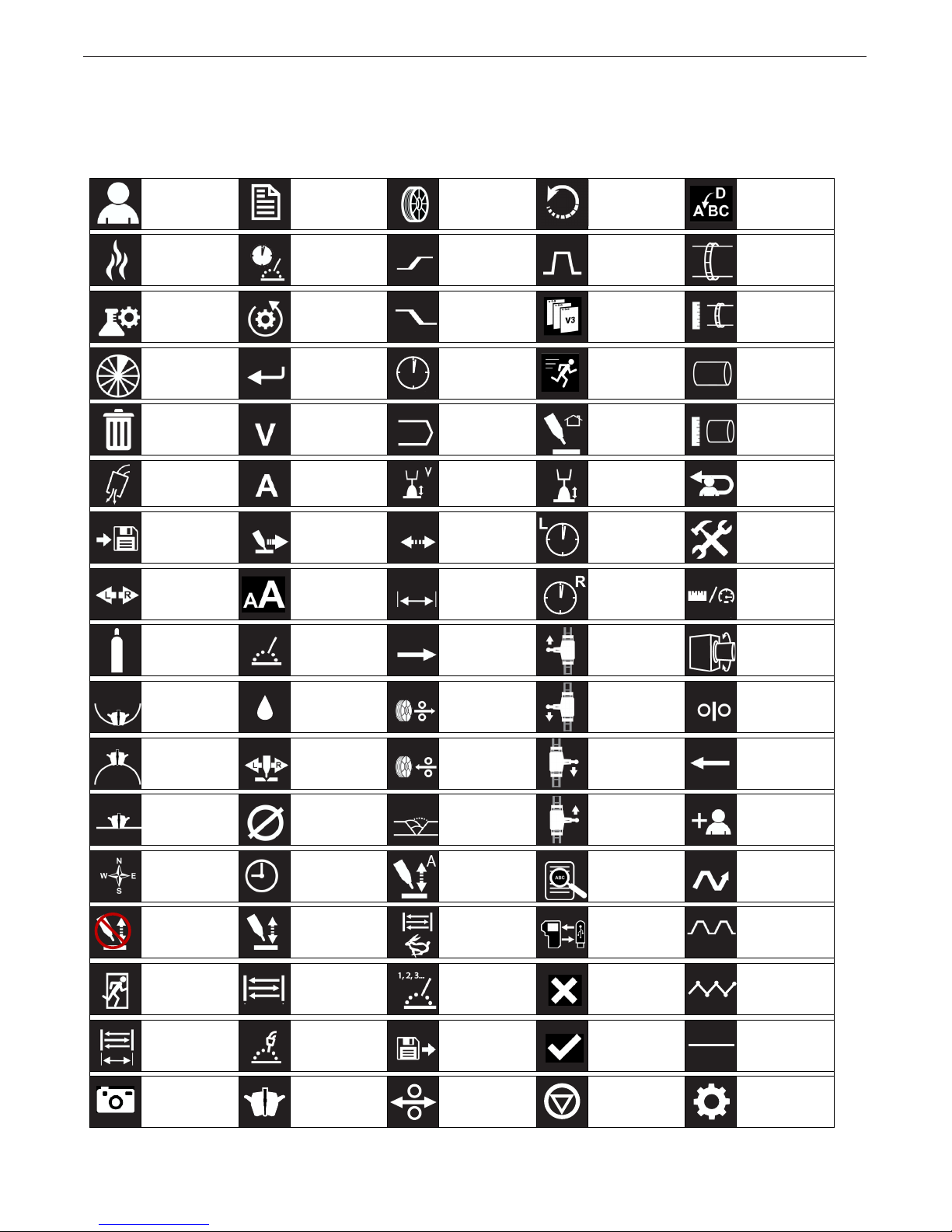
Symbols & Icons
This list is a quick reference for all icons from the
pendant and on the control unit.
OPERATION
Users Set Up/
Modes
Weld Weld Time Upslope /
Test Mode Reset
Settings
Segment Enter Time Motion Pipe
Trash Voltage Program Return Home Pipe
Gas Purge
Pre/Post Flow
Save Travel /
Swap Shift Case Osc Width Right Dwell Increment
Gas Advanced
Amperage Trim Volts Trim Log Out
Travel Setup
Settings
Wire Reboot Insert
Process Track Ring
Start Settings
Downslope /
End Settings
Osc Speed Left Dwell Settings /
Next /
Index
Version Track Ring
Diameter
Diameter
Service Page
Unit Settings
Travel
Direction
Positioner
ID Track
OD Track Steering /
Flat Track Wire Diam-
Direction Delay Amps Details Weave
Manual
Height
Exit Oscillation Mode
Oscillation
Width
Snapshot
Kilowatts Wire Feed Travel
Water
K
Wire
Oscillator
eter
Torch/Auto
Height
Weld Mode Load Okay No Weave
Weld Head Wire On Faults
Retract
Pass Travel
Oscillation
Speed
Select
Direction
Travel
Direction
Direction
Copy To Constant
Cancel Step
Wire / Wire
Feed Speed
Previous /
Index
Add User
Type
Travel
Travel
Travel
Settings
10
APEX® 3 SERIES MIG PENDANT MANUAL
OPERATION
Safety Precautions
Read entire manual before installation or operation.
WARNING
ELECTRIC SHOCK CAN KILL
• Only qualied personnel
should perform this
installation.
• Turn the input power OFF at
the disconnect switch or fuse
box before working on this
equipment turn off the input
power to any other equipment
connected to the welding system at the disconnect switch or fuse box before working on the
equipment.
• Do not touch electrically hot parts.
• Always connect the power supply grounding lug
to a proper safety (Earth) ground.
Proper handling
The APEX® 3 Series Pendant is designed to be turned
on and off through the welding power supply. The
pendant should be kept dry and sheltered from rain
and snow. Do not place or drop the pendant on wet
ground or in puddles. Always place the pendant on a
sturdy, at level surface when not in use and be sure to
unplug it.
Keep hands away from weld head, wire feeder and
other moving parts while in operation. Read this entire
process and operations manual before using the
equipment.
OPERATION
Explanation of Welding Terms
GMAW: Gas Metal Arc Welding
FCAW: Flux Cored Arc Welding
STT: Surface Tension Transfer
WFS: Wire Feed Speed
OSC: Oscillation
ACC: Automatic Current Control
AHC: Automatic Height Control
ID: Inside Diameter
OD: Outside Diameter
WFS: Wire Feed Speed
IPM: Inches per minute
CM/MIN: Centimeters per minute
Volts: Voltage
Amps: Amperage
Only operate the system while on a rm level surface.
Always verify that the system cart is secured in place
before operating the system.
Keep hands away from weld head, wire feeder and
other moving parts while in operation.
CAUTION
Never unplug or plug in control cables to the weld
head while the system is powered on.
Verify that the system is properly grounded before
beginning to weld.
Refer to the individual components manuals for additional instructions.
11
APEX® 3 SERIES MIG PENDANT MANUAL
System Start Up
Ensure all components are connected. Refer to the
individual component manuals for full connection
instructions.
Prior to beginning the weld, turn on the welding
power supply. The system is designed to be turned
on and off through the welding power supply.Ensure
all components are connected. Refer to the individual
component manuals for full connection instructions.
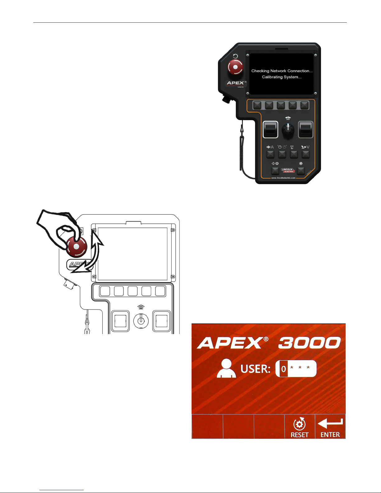
Note: With power applied to the system, check the
reset button. If the reset button is engaged
the system will not initialize. To disengage the
reset button, rotate the knob clockwise. See
FIGURE 1 - APEX Pendant Reset Button.
This reset button can be used to restart the system
for troubleshooting purposes and to halt welding and
system movement.
OPERATION
FIGURE 2 - Startup Screen
Startup Screen
When the system is reset at the Power Wave®, the
screen will display “Checking Network Connection...
Calibrating System – FIGURE 2 - Startup Screen.
This is a normal part of the initialization process.
Note: During the start up interval, the weld head goes
through a self-calibration cycle. The system will
not allow the user to log in until the calibration
cycle has been completed.
When the system is fully calibrated, the user is presented with a log in screen – see FIGURE 3 - Log In
Screen. Log in to begin use. See the next sections for
pendant operation.
FIGURE 1 - Pendant Reset Button
FIGURE 3 - Log In Screen
B-1

APEX® 3 SERIES MIG PENDANT MANUAL
OPERATION
Pendant Operation
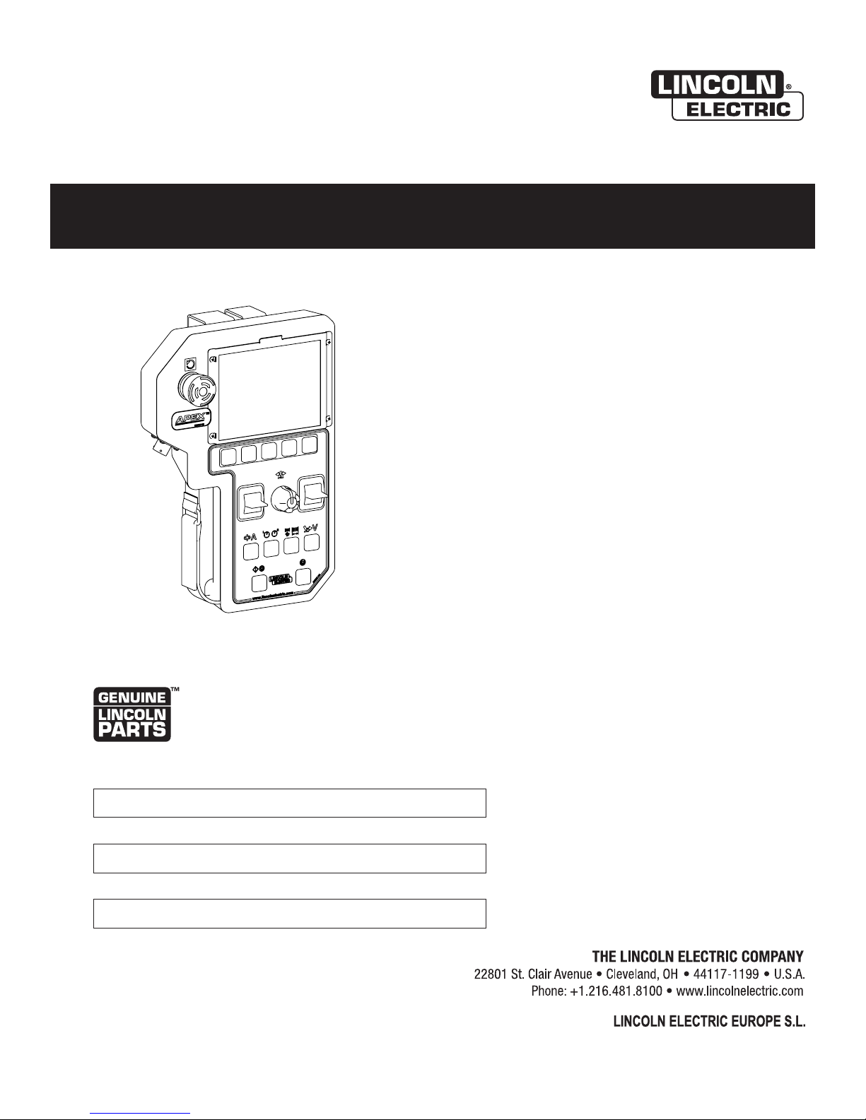
The APEX 3 Series Pendant is designed around full
functionality and easy operator experience. The pendant’s buttons serve multiple purposes, depending on
the screen display. See FIGURE 4 - Pendant Items on
page B-3 – to review each button, knob and switch on
the pendant.
Button Actions
Each of the buttons and toggles may perform
differently depending on how the buttons are pressed.
Listed below are the four types of button presses.
1. SHORT PRESS
A short press is a standard press that engages the
button and is not held in place. Most operations are
performed as a short press.
Example: Quickly pressing down button 7 will center the
oscillator.
2. LONG PRESS
For some screens, holding a button down for a
length of time exceeding two seconds signals the
system to perform an alternate function.
Example: A long press of more than two seconds on button 7 will start the oscillation test mode on some screens.
3. HOLD
By pressing and holding down a button or toggle,
the effects exhibited will continue or speed up.
Example: When pressing button 1 in the jog screen,
gas will purge for three seconds. Holding down button 1
will cause the gas to continuously purge.
4. HOLD AND ROTATE
The steering knob also acts as a button. It can be
pressed or rotated for different actions for some
screens. It can also be held down and rotated
for faster navigation.
6. LEFT TOGGLE (WHITE BORDER)
• Short Press – Navigates or changes the selected
value (in this example, it will change the value in
the left dwell box)
• Hold – Increases or decreases value / change
speed on some screens
7. STEERING KNOB
• Rotate – Steers oscillation in and out or changes
the selected variable
• Short Press – Centers the oscillation or moves to
the next variable
• Long Press – Starts / Stops oscillation test
(in idle mode only)
• Hold & Rotate – Fast navigation between
selected variables
8. RIGHT TOGGLE (GRAY BORDER)
• Short Press – Navigates or changes the selected
value (in this example, it will change the value in
the right dwell box)
• Hold – Increases or decreases value / changes
speed on some screens
Selection Buttons
Buttons 1 through 5 are selection buttons. Their
functions change depending on the screen. In each
screen there will be an icon just above the button to
indicate its function. A short press enables, disables or
selects the shown variable.
Navigation Controls
Items 6 through 8 control navigation. They function
primarily for navigating through the menus and
changing values while setting up the system.
Note: When welding, steering knob 7 functions
only for steering or oscillation steering
if oscillation is enabled.
B-2
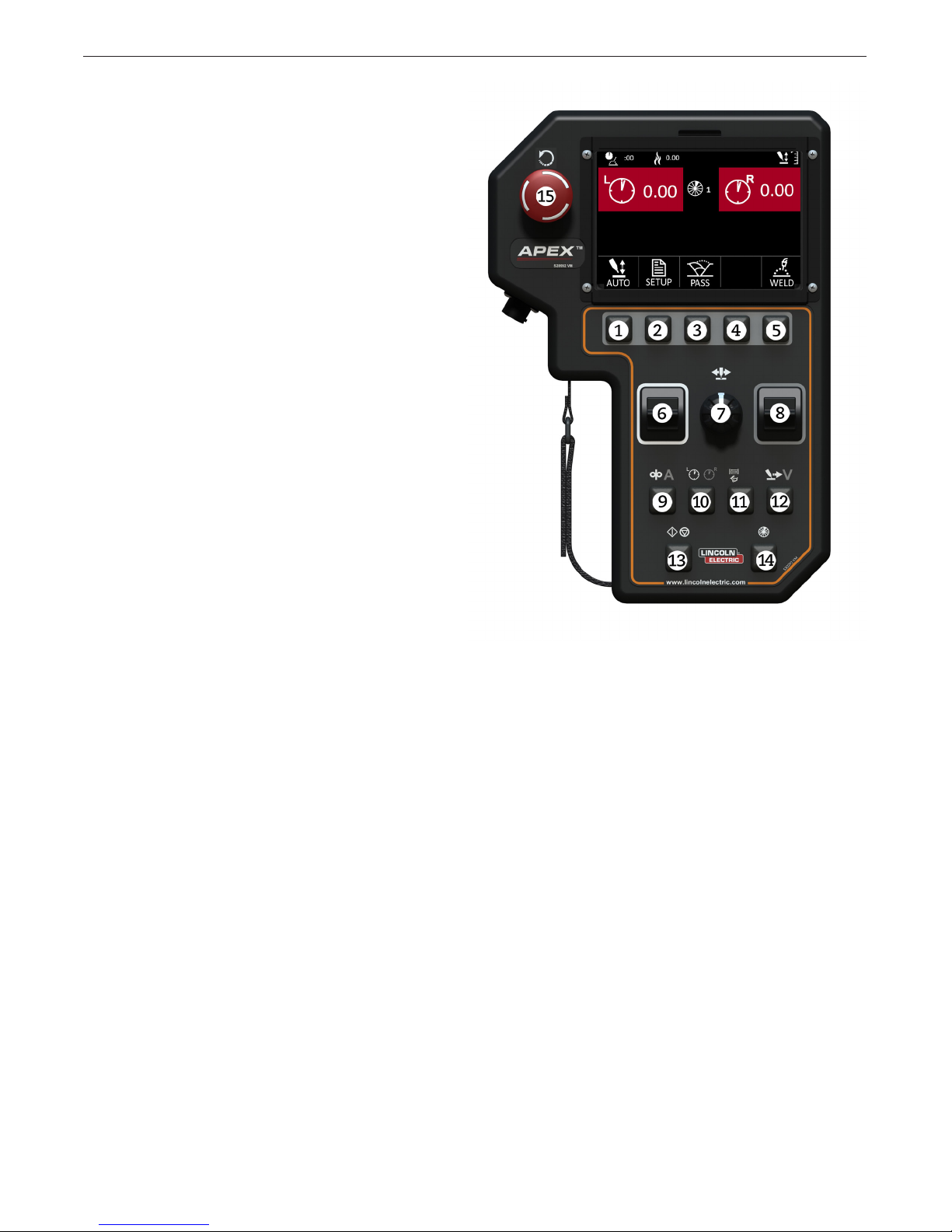
APEX® 3 SERIES MIG PENDANT MANUAL
Menu Buttons
Buttons 9 through 12 are the menu buttons. Pressing
one of these buttons will bring up a menu while in the
idle, test or welding screens.
9. WIRE FEED/AMPS
• Short Press – Wire Feed/Amps options
• Long Press – Navigates to the Jog Screen from
the Idle Weld screen
10. DWELL
• Short Press – Dwell options
• Long Press – Navigates to the Oscillation Screen
from the Idle Weld screen
11. OSCILLATION
• Short Press – Oscillation options
• Long Press – Navigates to the Oscillation Screen
from the Idle Weld screen
12. TRAVEL/VOLTS
OPERATION
• Short Press - Travel/voltage options
• Long Press - Navigates to the jog screen
from the idle weld screen
Control Buttons
Buttons 13 through 15 are the pendant control
buttons. These buttons have specic purposes that
typically do not change.
Note: The control buttons may be disabled in
menu screens.
13. START/STOP
• Short Press – Start if idle, stop if welding, stop/
start test weld when in test mode
14. SECTOR
• Short Press – Switches between sectors and
changes passes (if available) on the Increments
screen.
15. RESET –
• Short Press – stops the welding sequence
and all motion
• Twist Release
IMPORTANT! The reset button is not an emergency
stop button. Power is still being applied to the system.
FIGURE 4 - Pendant Items
Color Coding
The menu buttons and toggles are color-coded. For
example, the icons above button 9 are Wire Feed
(white icon) and Amps (gray icon). When the operator
presses the 9 button in the weld (idle) screen, the value
for the Wire Feed (white icon) will be presented and
can be changed by the left toggle (white border) and
the value for Amps (gray icon) will be presented and
can be changed by the right toggle (gray border).
Fast Movement
Certain screens allow for fast movement using the
steering knob. Movement and selection can still be
accomplished with the left and right toggle. In addition
the steering knob will allow the user to change the
selection by turning the knob and moving to the next
section by pressing the knob.
For fast movement between selections hold the steering knob down while turning to rapidly move from one
selection to the other.
B-3
APEX® 3 SERIES MIG PENDANT MANUAL
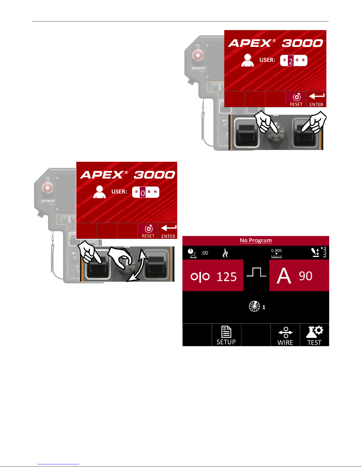
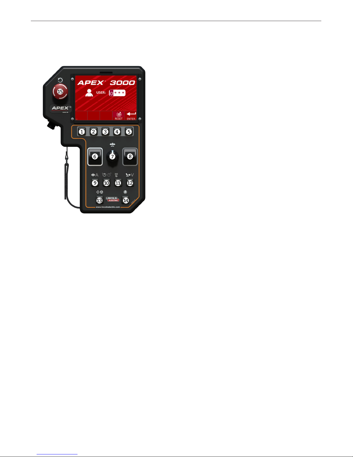
System Log In
When powered on, the system will go through a
self-calibration routine. Make sure the torch is free to
move before starting the system.
When the calibration routine is complete, the user
will be presented with a Log In Screen – see FIGURE
3 - Log In Screen on page B-1 and FIGURE 6 Change User. The system requires a four-digit user
code to log in.
Fast Movement
Fast movement using the steering knob is enabled on
this screen – see FIGURE 5 - Fast Movement. Use
the steering knob or left and right toggles for navigation and selection.
OPERATION
FIGURE 6 - Change User
Press the Enter Selection button when the complete
four digit user code has been entered. Once a four digit code is accepted, the system automatically moves
into the default Idle screen – see FIGURE 7- Idle
Screen Default. This screen is shown when a supervisor logs into the system. Logging in as an operator will
default to the Program Load Screen.
FIGURE 5 - Fast Movement
Use the left toggle or press the steering knob to
change from one variable to the next. Use the right
toggle or turn the steering knob to change the selected
variable.
FIGURE 7 - Idle Screen Default
B-4
APEX® 3 SERIES MIG PENDANT MANUAL
OPERATION
Log In Screen
The following buttons and options are available from
the log in screen – see FIGURE 8 - Log in Buttons.
7. STEERING KNOB
• Short Press – Moves cursor to the next space
• Rotation – Quickly cycles through available
character options
• Hold & Rotate – Quickly moves the cursor from
one selection to the next
8. RIGHT TOGGLE (Gray Border)
• Short Press – Pressing up or down changes
value of the selection
9. WIRE FEED/AMPS
• No Effect
10. DWELL
• No Effect
11. OSCILLATION
• No Effect
12. TRAVEL/VOLTs
• No Effect
13. START/STOP
• No Effect
FIGURE 8 - Log in Buttons
1. N/A
• No Effect
2. N/A
• No Effect
3. N/A
• No Effect
4. RESET
• Short Press – Will change password entry back
to “0000”
5. ENTER
• Short Press – Attempts to log in to the system
with the currently entered user code
6. LEFT TOGGLE (White Border)
• Short Press – Pressing up or down moves cursor
between spaces
14. SECTOR
• No Effect
15. Short Press – stops the welding sequence
and all motion
• Twist Release
B-5
APEX® 3 SERIES MIG PENDANT MANUAL
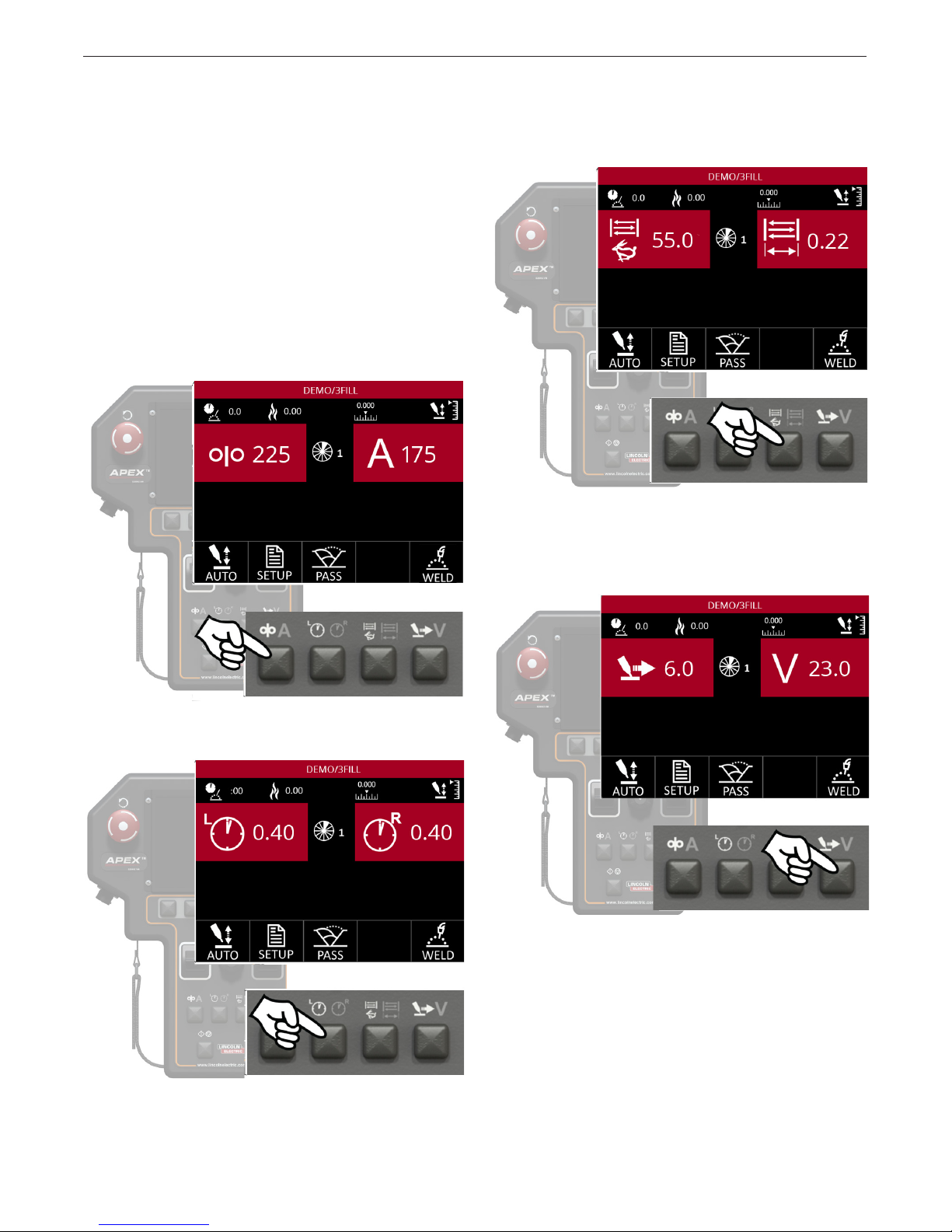
OPERATION
Idle Screen
The Idle Screen is the rst screen presented to a
supervisor when logging in – see FIGURE 7 - Idle
Screen Default on page B-4. This screen allows the
supervisor to set up all parameters for welding, test the
parameters if necessary and to start welding.
Menu Option Variables
The Idle Screen will show the user eight variables (two
variables on four separate screens), depending on
which Menu button has been pressed. Pressing the
different Menu buttons will change the values shown.
The different variables shown correspond to the icons
on the Menu buttons.
Similar variables are paired together. The variables
shown on the screen can be changed using the left
and right toggles. It is possible to change between
these menu options while idle or welding.
Press the Menu button to open the
Oscillation Menu options
Press the Menu button to open
the Wire Feed/Amps Menu options
Press the Menu button to open
the Dwell Menu options
Press the Menu button to open
the Travel/Voltage Menu options
B-6
 Loading...