

Page 1
Operator’s Manual
Register your machine:
www.lincolnelectric.com/register
Authorized Service and Distributor Locator:
www.lincolnelectric.com/locator
IM10458-A | Issue D ate Apr-19
© Lincoln Global, Inc. All Rights Reserved.
For use with machines having Code Numbers:
12759, 12877
Save for future reference
Date Purchased
Code: (ex: 10859)
Serial: (ex: U1060512345)
Activ8X
™
Page 2
THANK YOU FOR SELECTING
A QUALITY PRODUCT BY
LINCOLN ELEC TRIC.
PLEASE EXAMINE CARTON AND EQUIPMENT FOR
DAMAGE IMMEDIATELY
When this equipment is shipped, title passes to the purchaser
upon receipt by the carrier. Consequently, claims for material
damaged in shipment must be made by the purchaser against the
transportation company at the time the shipment is received.
SAFETY DEPENDS ON YOU
Lincoln arc welding and cutting equipment is designed and built
with safety in mind. However, your overall safety can be increased
by proper installation ... and thoughtful operation on your part.
DO NOT INSTALL, OPERATE OR REPAIR THIS EQUIPMENT
WITHOUT READING THIS MANUAL AND THE SAFETY
PRECAUTIONS CONTAINED THROUGHOUT. And, most importantly,
think before you act and be careful.
This statement appears where the information must be followed
exactly to avoid serious personal injury or loss of life.
This statement appears where the information must be followed
to avoid minor personal injury or damage to this equipment.
KEEP YOUR HEAD OUT OF THE FUMES.
DON’T get too close to the arc.
Use corrective lenses if necessary
to stay a reasonable distance
away from the arc.
READ and obey the Safety Data
Sheet (SDS) and the warning label
that appears on all containers of
welding materials.
USE ENOUGH VENTILATION or
exhaust at the arc, or both, to
keep the fumes and gases from
your breathing zone and the general area.
IN A LARGE ROOM OR OUTDOORS, natural ventilation may be
adequate if you keep your head out of the fumes (See below).
USE NATURAL DRAFTS or fans to keep the fumes away
from your face.
If you de velop unusual symptoms, see your supervisor.
Perhaps the welding atmosphere and ventilation system
should be checked.
WEAR CORRECT EYE, EAR &
BODY PROTECTION
PROTECT your eyes and face with welding helmet
properly fitted and with proper grade of filter plate
(See ANSI Z49.1).
PROTECT your body from welding spatter and arc
flash with protective clothing including woolen
clothing, flame-proof apron and gloves, leather
leggings, and high boots.
PROTECT others from splatter, flash, and glare
with protective screens or barriers.
IN SOME AREAS, protection from noise may be appropriate.
BE SURE protective equipment is in good condition.
Also, wear safety glasses in work area
AT ALL TIMES.
SPECIAL SITUATIONS
DO NOT WELD OR CUT containers or materials which previously
had been in contact with hazardous substances unless they are
properly cleaned. This is extremely dangerous.
DO NOT WELD OR CUT painted or plated parts unless special
precautions with ventilation have been taken. They can release
highly toxic fumes or gases.
Additional precautionary measures
PROTECT compressed gas cylinders from excessive heat,
mechanical shocks, and arcs; fasten cylinders so they cannot fall.
BE SURE cylinders are never grounded or part of an
electrical circuit.
REMOVE all potential fire hazards from welding area.
ALWAYS HAVE FIRE FIGHTING EQUIPMENT READY FOR
IMMEDIATE USE AND KNOW HOW TO USE IT.
WARNING
CAUTION
Safety 01 of 04 - 5/16/2018
Page 3
SECTION A:
WARNINGS
CALIFORNIA PROPOSITION 65 WARNINGS
WARNING: Breathing diesel engine exhaust
exposes you to chemicals known to the State
of California to cause cancer and birth defects,
or other reproductive harm.
• Always start and operate the engine in a
well-ventilated area.
• If in an exposed area, vent the exhaust to the outside.
• Do not modify or tamper with the exhaust system.
• Do not idle the engine except as necessary.
For more information go to
www.P65 warnings.ca.gov/diesel
WARNING: This product, when used for welding or
cutting, produces fumes or gases which contain
chemicals known to the State of California to cause
birth defects and, in some cases, cancer. (California
Health & Safety Code § 25249.5 et seq.)
WARNING: Cancer and Reproductive Harm
www.P65warnings.ca.gov
ARC WELDING CAN BE HAZARDOUS. PROTECT
YOURSELF AND OTHERS FROM POSSIBLE SERIOUS
INJURY OR DEATH. KEEP CHILDREN AWAY.
PACEMAKER WEARERS SHOULD CONSULT WITH
THEIR DOCTOR BEFORE OPERATING.
Read and understand the following safety highlights. For
additional safety information, it is strongly recommended
that you purchase a copy of “Safety in Welding & Cutting ANSI Standard Z49.1” from the American Welding Society,
P.O. Box 351040, Miami, Florida 33135 or CSA Standard
W117.2-1974. A Free copy of “Arc Welding Safety” booklet
E205 is available from the Lincoln Electric Company,
22801 St. Clair Avenue, Cleveland, Ohio 44117-1199.
BE SURE THAT ALL INSTALLATION, OPERATION,
MAINTENANCE AND REPAIR PROCEDURES ARE
PERFORMED ONLY BY QUALIFIED INDIVIDUALS.
FOR ENGINE POWERED
EQUIPMENT.
1.a. Turn the engine off before troubleshooting
and maintenance work unless the
maintenance work requires it to be running.
1.b. Operate engines in open, well-ventilated areas or vent the engine
exhaust fumes outdoors.
1.c. Do not add the fuel near an open flame welding
arc or when the engine is running. Stop the
engine and allow it to cool before refueling to
prevent spilled fuel from vaporizing on contact
with hot engine parts and igniting. Do not spill fuel when filling
tank. If fuel is spilled, wipe it up and do not start engine until
fumes have been eliminated.
1.d. Keep all equipment safety guards, covers
and devices in position and in good repair.
Keep hands, hair, clothing and tools away
from V-belts, gears, fans and all other
moving parts when starting, operating or
repairing equipment.
1.e. In some cases it may be necessary to remove safety guards to
perform required maintenance. Remove guards only when
necessary and replace them when the maintenance requiring
their removal is complete. Always use the greatest care when
working near moving parts.
1.f. Do not put your hands near the engine fan. Do not attempt to
override the governor or idler by pushing on the throttle control
rods while the engine is running.
1.g. To prevent accidentally starting gasoline engines while turning
the engine or welding generator during maintenance work,
disconnect the spark plug wires, distributor cap or magneto wire
as appropriate.
1.h. To avoid scalding, do not remove the radiator
pressure cap when the engine is
hot.
ELECTRIC AND
MAGNETIC FIELDS MAY
BE DANGEROUS
2.a. Electric current flowing through any conductor
causes localized Electric and Magnetic Fields (EMF).
Welding current creates EMF fields around welding cables
and welding machines
2.b. EMF fields may interfere with some pacemakers, and
welders having a pacemaker should consult their physician
before welding.
2.c. Exposure to EMF fields in welding may have other health effects
which are now not known.
2.d. All welders should use the following procedures in order to
minimize exposure to EMF fields from the welding circuit:
2.d.1. Route the electrode and work cables together - Secure
them with tape when possible.
2.d.2. Never coil the electrode lead around your body.
2.d.3. Do not place your body between the electrode and work
cables. If the electrode cable is on your right side, the
work cable should also be on your right side.
2.d.4. Connect the work cable to the workpiece as close as possible to the area being welded.
2.d.5. Do not work next to welding power source.
SAFETY
Safety 02 of 04 - 5/16/2018
Page 4
ELECTRIC SHOCK
CAN KILL.
3.a. The electrode and work (or ground) circuits are
electrically “hot” when the welder is on. Do
not touch these “hot” parts with your bare skin or wet clothing.
Wear dry, hole-free gloves to insulate hands.
3.b. Insulate yourself from work and ground using dry insulation.
Make certain the insulation is large enough to cover your full area
of physical contact with work and ground.
In addition to the normal safety precautions, if
welding must be performed under electrically
hazardous conditions (in damp locations or while
wearing wet clothing; on metal structures such as
floors, gratings or scaffolds; when in cramped
positions such as sitting, kneeling or lying, if there
is a high risk of unavoidable or accidental contact
with the workpiece or ground) use the following
equipment:
• Semiautomatic DC Constant Voltage (Wire) Welder.
• DC Manual (Stick) Welder.
• AC Welder with Reduced Voltage Control.
3.c. In semiautomatic or automatic wire welding, the electrode,
electrode reel, welding head, nozzle or semiautomatic welding
gun are also electrically “hot”.
3.d. Always be sure the work cable makes a good electrical
connection with the metal being welded. The connection should
be as close as possible to the area being welded.
3.e. Ground the work or metal to be welded to a good electrical (earth)
ground.
3.f. Maintain the electrode holder, work clamp, welding cable and
welding machine in good, safe operating condition. Replace
damaged insulation.
3.g. Never dip the electrode in water for cooling.
3.h. Never simultaneously touch electrically “hot” parts of electrode
holders connected to two welders because voltage
between the
two can be the total of the open circuit voltage of both
welders.
3.i. When working above floor level, use a safety belt to protect
yourself from a fall should you get a shock.
3.j. Also see It ems 6.c. and 8.
ARC RAYS CAN BURN.
4.a. Use a shield with the proper filter and cover plates to protect your
eyes from sparks and the rays of the arc when welding or
observing open arc welding. Headshield and filter lens should
conform to ANSI Z87. I standards.
4.b. Use suitable clothing made from durable flame-resistant material
to protect your skin and that of your helpers from the arc rays.
4.c. Protect other nearby personnel with suitable, non-flammable
screening and/or warn them not to watch the arc nor expose
themselves to the arc rays or to hot spatter or metal.
FUMES AND GASES
CAN BE DANGEROUS.
5.a. Welding may produce fumes and gases
hazardous to health. Avoid breathing these
fumes and gases. When welding, keep your head out of the fume.
Use enough ventilation and/or exhaust at the arc to keep fumes
and gases away from the breathing zone. When welding
hardfacing (see instructions on container or SDS)
or on lead or cadmium plated steel and other
metals or coatings which produce highly toxic
fumes, keep exposure as low as possible and
within applicable OSHA PEL and ACGIH TLV limits
using local exhaust or mechanical ventilation
unless exposure assessments indicate otherwise.
In confined spaces or in some circumstances,
outdoors, a respirator may also be required.
Additional precautions are also required when
welding
on galvanized steel.
5. b. The operation of welding fume control equipment is affected by
various factors including proper use and positioning of the
equipment, maintenance of the equipment and the specific
welding procedure and application involved. Worker exposure
level should be checked upon installation and periodically
thereafter to be certain it is within applicable OSHA PEL and
ACGIH TLV limits.
5.c. Do not weld in locations near chlorinated hydrocarbon vapors
coming from degreasing, cleaning or spraying operations. The
heat and rays of the arc can react with solvent vapors to form
phosgene, a highly toxic gas, and other irritating products.
5.d. Shielding gases used for arc welding can displace air and
cause
injury or death. Always use enough ventilation, especially in
confined areas, to insure breathing air is safe.
5.e. Read and understand the manufacturer’s instructions for this
equipment and the consumables to be used, including the
Safety Data Sheet (SDS) and follow your employer’s safety
practices. SDS forms are available from your welding
distributor or from the manufacturer.
5.f. Also see item 1.b.
SAFETY
Safety 03 of 04 - 5/16/2018
Page 5
WELDING AND CUTTING
SPARKS CAN CAUSE
FIRE OR EXPLOSION.
6.a. Remove fire hazards from the welding area. If
this is not possible, cover them to prevent the welding sparks
from starting a fire. Remember that welding sparks and hot
materials from welding can easily go through small cracks and
openings to adjacent areas. Avoid welding near hydraulic lines.
Have a fire extinguisher readily available.
6.b. Where compressed gases are to be used at the job site, special
precautions should be used to prevent hazardous situations.
Refer to “Safety in Welding and Cutting” (ANSI Standard Z49.1)
and the operating information for the equipment being used.
6.c. When not welding, make certain no part of the electrode circuit is
touching the work or ground. Accidental contact can cause
overheating and create a fire hazard.
6.d. Do not heat, cut or weld tanks, drums or containers until the
proper steps have been taken to insure that such procedures
will not cause flammable or toxic vapors from substances inside.
They can cause an explosion even though they have been
“cleaned”. For information, purchase “Recommended Safe
Practices for the Preparation for Welding and Cutting of
Containers and Piping That Have Held Hazardous Substances”,
AWS F4.1 from the American Welding Society
(see address above).
6.e. Vent hollow castings or containers before heating, cutting or
welding. They may explode.
6.f. Sparks and spatter are thrown from the welding arc. Wear oil free
protective garments such as leather gloves, heavy shirt, cuffless
trousers, high shoes and a cap over your hair. Wear ear plugs
when welding out of position or in confined places. Always wear
safety glasses with side shields when in a welding area.
6.g. Connect the work cable to the work as close to the welding area
as practical. Work cables connected to the building framework or
other locations away from the welding area increase the
possibility of the welding current passing through lifting chains,
crane cables or other alternate circuits. This can create fire
hazards or overheat lifting chains or cables until they fail.
6.h. Also see item 1.c.
6.I. Read and follow NFPA 51B “Standard for Fire Prevention During
Welding, Cutting and Other Hot Work”, available from NFPA, 1
Batterymarch Park, PO box 9101, Quincy, MA 022690-9101.
6.j. Do not use a welding power source for pipe thawing.
CYLINDER MAY EXPLODE IF
DAMAGED.
7.a. Use only compressed gas cylinders containing
the correct shielding gas for the process used
and properly operating regulators designed for
the gas and pressure used. All hoses, fittings,
etc. should be suitable for the application and
maintained in good condition.
7.b. Always keep cylinders in an upright position securely chained to
an undercarriage or fixed support.
7.c. Cylinders should be located:
• Away from areas where they may be struck or subjected
to physical damage.
• A safe distance from arc welding or cutting operations
and any other source of heat, sparks, or flame.
7.d. Never allow the electrode, electrode holder or any other
electrically “hot” parts to touch a cylinder.
7.e. Keep your head and face away from the cylinder valve outlet
when opening the cylinder valve.
7.f. Valve protection caps should always be in place and hand tight
except when the cylinder is in use or connected for use.
7.g. Read and follow the instructions on compressed gas cylinders,
associated equipment, and CGA publication P-l, “Precautions for
Safe Handling of Compressed Gases in Cylinders,” available from
the Compressed Gas Association, 14501 George Carter Way
Chantilly, VA 20151.
FOR ELECTRICALLY
POWERED EQUIPMENT.
8.a. Turn off input power using the disconnect
switch at the fuse box before working on
the equipment.
8.b. Install equipment in accordance with the U.S. National Electrical
Code, all local codes and the manufacturer’s recommendations.
8.c. Ground the equipment in accordance with the U.S. National
Electrical Code and the manufacturer’s recommendations.
Refer to
http://www.lincolnelectric.com/safety
for additional safety information.
SAFETY
Safety 04 of 04 - 5/16/2018
Page 6

2
ACTIV8X™
TABLE OF CONTENTS
GENERAL DESCRIPTION........................................................................................................................................3
RECOMMENDED PROCESSES ...............................................................................................................................3
PROCESS LIMITATIONS.........................................................................................................................................3
EQUIPMENT LIMITATIONS .....................................................................................................................................3
RECOMMENDED POWER SOURCES.......................................................................................................................3
OTHER POWER SOURCES......................................................................................................................................3
DESIGN FEATURES................................................................................................................................................3
INSTALLATION .............................................................................................................................................SECTION A
TECHNICAL SPECIFICATIONS ............................................................................................................................A-1
LOCATION .........................................................................................................................................................A-2
ACROSS THE ARC SET-UP WITH CROSSLINC™ (RECOMMENDED).....................................................................A-3
ACROSS THE ARC SET-UPS WITHOUT CROSSLINC™ ........................................................................................A-3
RECOMMENDED ELECTRODE AND WORK CABLE SIZES FOR ARC WELDING ......................................................A-5
TRIGGER CONNECTOR.......................................................................................................................................A-5
CHANGING THE GUN ADAPTER BUSHING ...........................................................................................................A-6
PROCEDURE TO INSTALL DRIVE ROLLS AND WIRE GUIDES................................................................................A-7
PRESSURE ARM ADJUSTMENT..........................................................................................................................A-7
GUN CONNECTION.............................................................................................................................................A-8
SHIELDING GAS CONNECTION ...........................................................................................................................A-8
OPERATION ................................................................................................................................................SECTION B
POWER-UP SEQUENCE......................................................................................................................................B-1
CASE FRONT CONTROLS...................................................................................................................................B-2
INTERNAL CONTROLS .......................................................................................................................................B-3
REAR CONTROLS ..............................................................................................................................................B-4
DIGITAL METER OPERATION..............................................................................................................................B-5
SET-UP MENU OPERATION................................................................................................................................B-6
CONSTANT CURRENT OPERATION.....................................................................................................................B-9
OPTIONS/ACCESSORIES...............................................................................................................................SECTION C
MAINTENANCE .............................................................................................................................................SECTION D
ROUTINE MAINTENANCE ...................................................................................................................................D-1
PERIODIC MAINTENANCE ..................................................................................................................................D-1
TROUBLESHOOTING .....................................................................................................................................SECTION E
DIAGRAMS .................................................................................................................................................SECTION F
PARTS LIST ...............................................................................................................PARTS.LINCOLNELECTRIC.COM
CONTENT/DETAILS MAY BE CHANGED OR UPDATED WITHOUT NOTICE. FOR MOST CURRENT INSTRUCTION
MANUALS, GO TO PARTS.LINCOLNELECTRIC.COM.
Page 7

ACTIV8X™
General Description
The Activ8X™ is a rugged, portable, across-the-arc wire feeder
with CrossLinc™ and True Voltage Technology™. With its 8 in.
spool, the Activ8X is specifically designed for shipyards or field
construction where a smaller, portable wire feeder is needed.
When used with a CrossLinc equipped power source, this Activ8X
allows the user to adjust the welding voltage at the wire feeder
front panel without the need for a control cable. As a result, setup
and changeover time s reduced while productivity is increased.
True Voltage Technology™ (TVT™) does the thinking so you don’t
have to. TVT learns. In as little as one weld, TVT begins to make
the necessary power source adjustments to ensure that the
voltage you set at the feeder will be the same voltage delivered to
the arc. TVT remembers. Set point adjustments remain – even
after the power to the Activ8X has been removed.
The Activ8X comes factory equipped with a K1500-2 Magnum
®
Tweco-compatible style #2-#4 gun adapter. Other K1500 series
gun adapters are available as field installed options.
In addition to CrossLinc, the Activ8X wire feeder has the following
features:
• Rating- 330 amp, 60% duty cycle rating.
• Gas apparatus – can be used for FCAW-G and GMAW
processes.
• The plastic case is molded from a high impact, flame
retardant plastic for high durability and low weight.
• The heart of the Activ8X is the 2 roll MAXTRAC®drive. The
patented features on the wire drive offer tool-less changing of
the drive rolls and wire guides for quick spool changes. A
tachometer controlled motor powers the patented drive rolls
for smooth, steady feeding without slippage.
recoMMenDeD processes
• GMAW
• FCAW
process liMitations
• Not recommended for stitch or spot welding.
eQUipMent liMitations
• The duty cycle of the wire feeder is 330A, 60%. Duty cycle is
based upon the amount of welding performed in a 10 minute
period.
• The maximum spool size diameter is 8”.
• Maximum recommended FCAW gun length is 15 ft.
• Maximum recommended GMAW gun length is 15 ft.
• Push-pull guns do not work with the Activ8X™.
recoMMenDeD poWer soUrces
• Flextec 350X
™
• Flextec 500X
™
• Flextec 650X
™
otHer poWer soUrces
• CV-250, 300, 305, 400, 655
• DC-400, 600, 655
• Invertec V-350 Pro, V-450
• Multi-Weld 350
• Ranger 10,000, 3 Phase, 225, 250, 250 GXT
• Ranger 250 LPG, 305
• Cross Country 300
• Vantage 322, 435, 549, 565
• Air Vantage 566
• Dual Vantage 700
• Flextec 450, 500, 500P, 650
• Engine Drive Welder with a wire feed module
DesiGn FeatUres
Loaded with Standard Features Controls
• Digital Displays with large voltage and wire feed speed knobs.
• Trigger interlock for comfort when making long welds.
• Cold-feed switch for wire feeding without activating welding
output.
• Gas Purge switch for purging the gas path without activating
welding output.
• True Voltage Technology™ (TVT™) automatically
compensates for voltage drop between the power source and
the Activ8X. This ensures that the actual welding voltage
matches the preset voltage.
• The following options are available from the setup menu:
- CC/CV operation for accommodating constant current
power sources.
- Variable run-in for smoother arc starting.
- Burnback time provides adjustable power source output
shutoff to prevent the electrode from sticking in the
crater.
- Preflow and Postflow ensures proper gas shielding
coverage before and after each weld.
3
Page 8

A-1
INSTALLATIONACTIV8X™
tecHnical speciFications -
INPUT - SINGLE PHASE
Input Voltage +/- 10%
Input Amperes @ Rated
Output
15 - 110V DC
4
MODEL SUMMARY
K# Description Meters
Drive Roll Kit
Included
Feed Plate Gun Adapter
Installed
K3519-1 ACTIV8X™ DIGITAL ---- K1500-2
K3519-2 ACTIV8X™ DIGITAL ---- K1500-2
RATED OUTPUT (ALL MODELS)
Duty Cycle Amperes
60% 330A
PHYSICAL DIMENSIONS
Model Height Width Depth Weight
K3519-1
11.75 in
(298 mm)
7.4 in
(188 mm)
18.7 in
(475 mm)
27.5 lbs
(12.4 kg)
K3519-2
11.75 in
(298 mm)
7.4 in
(188 mm)
18.7 in
(475 mm)
27.5 lbs
(12.4 kg)
TEMPERATURE RANGES
OPERATING TEMPERATURE
RANGE
STORAGE TEMPERATURE
RANGE
-14°F to 104°F (-10°C to 40°C) -40°F to 122°F (-40°C to 50°C)
Thermal tests have been performed at ambient temperature. The duty cycle
(duty factor) at 40°C has been determined by simulation.
Process Wire Diameter Range Wire Feed Speed Range
GMAW 0.023 - 0.052” (0.6 - 1.3mm)
50 - 700 IPM (1.3 - 20.3 m/minute)
FCAW 0.035 - 5/64” (0.9 - 2.0mm)
Page 9

A-2
INSTALLATIONACTIV8X™
READ ENTIRE INSTALLATION SECTION BEFORE
INSTALLING THE ACTIV8X™ .
INSTALLATION
ELECTRIC SHOCK CAN KILL.
• Turn the input power OFF at the
disconnect switch or fuse box before
attempting to connect or disconnect
input power lines, output cables or
control cables.
• Only qualified personnel should perform this
installation.
• Do not touch metal portions of the Activ8X™ work clip
when the welding power source is on.
• Do not attach the work clip to the wire feeder.
• Connect the work clip directly to the work, as close as
possible to the welding arc.
• Turn power off at the welding power source before
disconnecting the work clip from the work.
• Only use on power sources with open circuit voltages
less than 110 VDC.
select sUitable location
For best wire feeding performance, place the Activ8X™ on a
stable and dry surface. Keep the wire feeder in a vertical
position. Do not operate the wire feeder on an angled surface of
more than 15 degrees.
Do not submerge the Activ8X™.
The Activ8X™ is rated IP23 and is suitable for outdoor use.
The handle of the Activ8X™ is intended for moving the wire
feeder about the work place only.
When suspending a wire feeder, insulate the hanging device from
the wire feeder enclosure.
High Frequency Interference Protection
Locate the Activ8X™ away from radio controlled machinery.
The normal operation of the Activ8X™ may adversely affect
the operation of RF controlled equipment, which may result
in bodily injury or damage to the equipment.
CAUTION
WARNING
Page 10
A-3
INSTALLATIONACTIV8X™
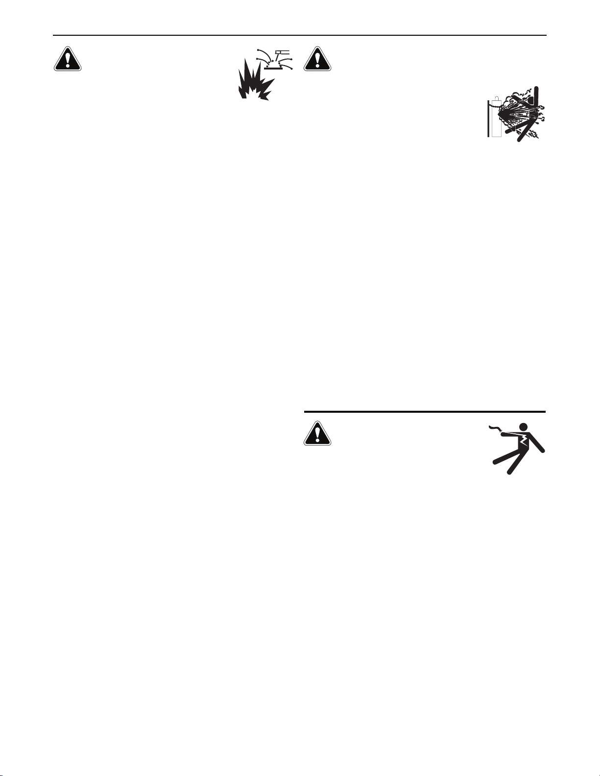
across tHe arc set-Up WitH crosslinc™
(recoMMenDeD)
Place the power source Local/Remote switch in the Remote
position. In many newer models of CrossLinc compatible power
sources, the Local/Remote switch is automatically overridden by
CrossLinc and there is no need to set it.
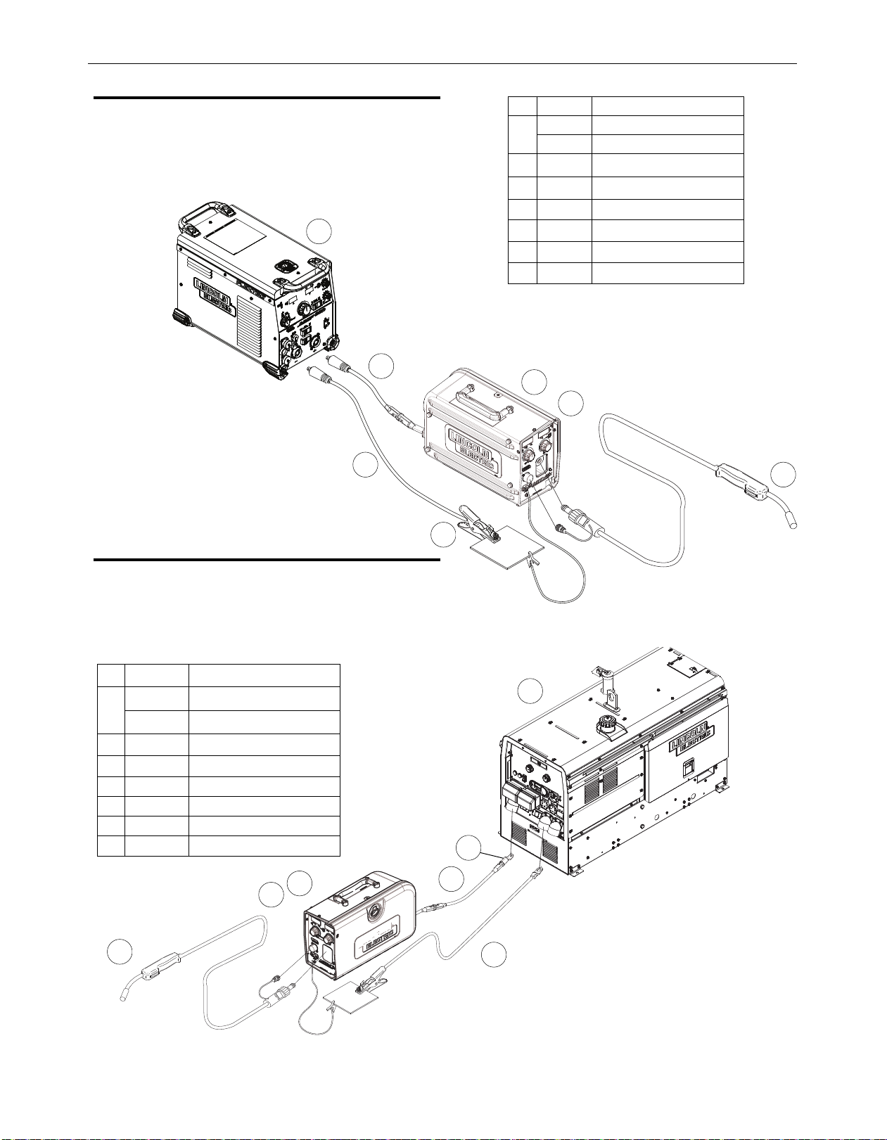
across tHe arc set-Ups WitHoUt crosslinc™
CV Power Sources with Stud Connectors with
Local/Remote Switch
Place the power source Remote/Local switch in the Local position.
+
_
Item
K#
Description
1
K3519-1
Activ8X™ (Tweco)
K3519-2
Activ8X™ CE (Twistmate/Dinse)
2
- Drive Roll Kit
3
- Welding Gun
4
-
Flextec 350X
™
5
- Work Cable
6
- Work Clamp
7
- Weld Power Cable
Item
K#
Description
1
K3519-1
Activ8X™ (Tweco)
K3519-2
Activ8X™ CE (Twistmate/Dinse)
2
- Drive Roll Kit
3
- Welding Gun
4
- CV power source
5
- Weld Power Cable
6
- Work Cable / w/ Clamp
7
- Lug to Tweco Adapter
1
1
3
3
7
5
7
6
5
6
4
4
2
2
CV-400
CV-600
DC-400
DC-600
DC-655
V450-PRO
SAE-400
w/ CV Adapter
Engine Drive Welder
w/ Wire Feed Module
Ranger 250 GXT
Vantage 520SD
Vantage 600
Air Vantage 600
Flextec 450
Flextec 500P
Page 11
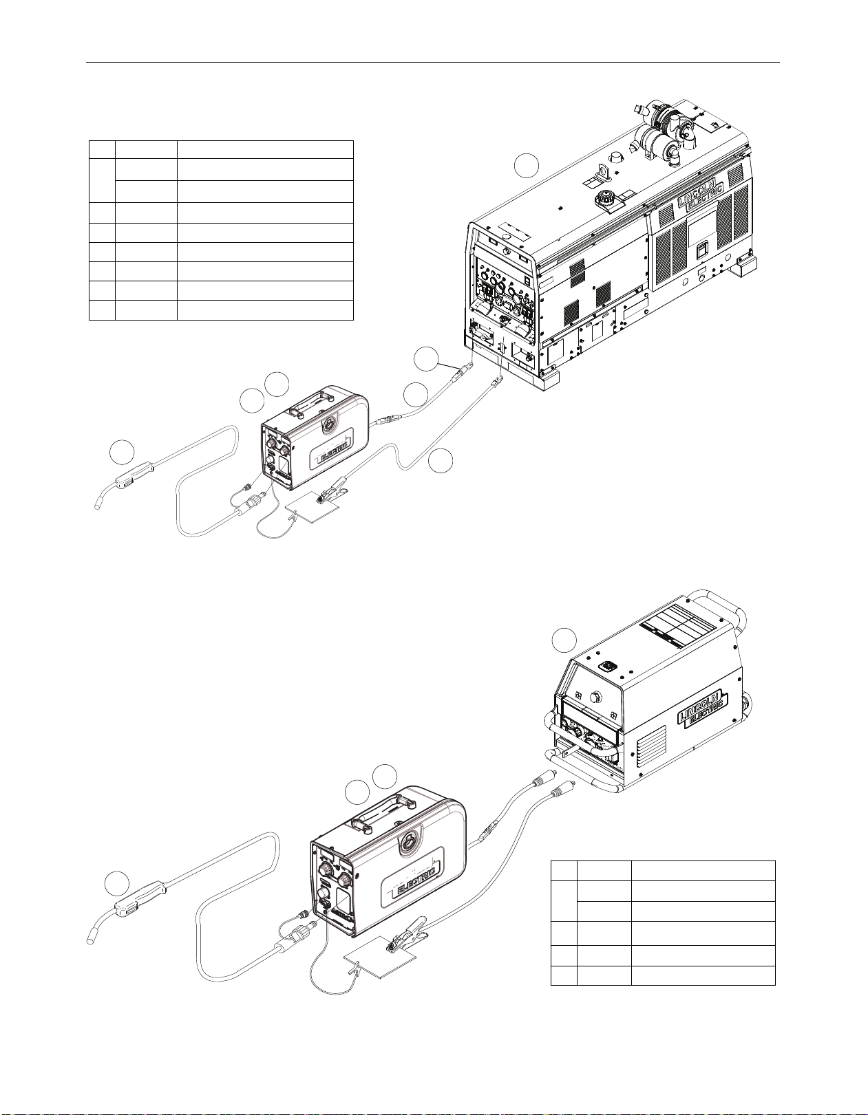
CV Power Sources with Stud Connectors and no
Remote/Local Switch
CV Power Source with Twist-Mate Connectors and
no Remote/Local Switch
A-4
INSTALLATIONACTIV8X™
Ranger 250
Ranger 250 LPG
Ranger 305G
Ranger 305D
Ranger 10,000
Ranger 3 Phase
Ranger 225
Ranger 225 GXT
Commander 300
Vantage 300
Vantage 400
Vantage 500
Air Vantage 500
Air Vantage 650
SAE 300
Dual Vantage 700
Classic 300
1
3
5
6
4
2
7
1
3
4
2
Item
K#
Description
1
K3519-1
Activ8X™ (Tweco)
K3519-2
Activ8X™ CE (Twistmate/Dinse)
2
- Drive Roll Kit
3
- Welding Gun
4
- CV power source
5
- Weld Power Cable
6
- Work Cable w/Clamp
7
- Lug to Tweco Adapter
Item
K#
Description
1
K3519-1
Activ8X™ (Tweco)
K3519-2
Activ8X™ CE (Twistmate/Dinse)
2
- Drive Roll Kit
3
- Welding Gun
4
- CV power source
+
_
Page 12

A-5
INSTALLATIONACTIV8X™
recoMMenDeD electroDe anD WorK cable
siZes For arc WelDinG
(See Table A.1)
Tabulated below are copper cable sizes recommended for
different currents and duty cycles. Lengths stipulated are the
distance from the welder through work and back to the welder
again. Cable sizes are increased for greater lengths primarily for
the purpose of minimizing cable drop.
triGGer connector
There is one circular connector for the gun trigger on the front of
the Activ8X™
ELECTRIC SHOCK CAN KILL.
• Do not touch electrically live parts.
WARNING
RECOMMENDED CABLE SIZES (RUBBER COVERED COPPER - RATED 167°F OR 75°C)**
Amperes
PERCENT
DUTY CYCLE
CABLE SIZES FOR COMBINED LENGTHS OF ELECTRODE AND WORK CABLES
0 to 50Ft.
(0 to15m)
50 to 100Ft.
(15 to 30m)
100 to 150 Ft.
(30 to 46m)
150 to 200 Ft.
(46 to 61m)
200 to 250 Ft.
(61 to 76m)
200
60
2
2
2
1 1/0
200
100
2 2
2
1 1/0
225
20
4 or 5
3
4 or 5
1
1/0
225
40 & 30
3
3
3
1
1/0
250
30
3
3
3
1 1/0
250
40
2
2
2
1
1/0
250
60
1 1
1
1
1/0
250
100
1 1
1
1 1/0
300
60
1 1
1
1/0 1/0
350
100
2/0
2/0
2/0
2/0 2/0
350
60
1/0 1/0
1/0
2/0 3/0
400
60
2/0 2/0
2/0
3/0 4/0
400
100
3/0 3/0
3/0
3/0
4/0
500
60
2/0
2/0
2/0
3/0 4/0
** Tabled values are for operation at ambient temperatures of 104°F(40°C) and below. Applications above 104°F(40°C) may require cables
larger than recommended, or cables rated higher than 167°F(75°C).
TABLE A.1
Picture Function Pin Wiring
5 PIN TRIGGER
CONNECTOR FOR
PUSH-ONLY GUNS.
A 15 VOLT SUPPLY
B NOT USED
C TRIGGER
D 83% WFS SWITCH
E 15 VOLT SUPPLY
A
E
C
B
D
Page 13

A-6
INSTALLATIONACTIV8X™
cHanGinG tHe GUn aDapter bUsHinG
ELECTRIC SHOCK CAN KILL.
• Turn the input power OFF at the welding
power source before installation or
changing drive rolls and/or guides.
• Do not touch electrically live parts.
• When inching with the gun trigger, electrode and drive
mechanism are "hot" to work and ground and could
remain energized several seconds after the gun trigger
is released.
• Do not operate with covers, panels or guards removed
or open.
• Only qualified personnel should perform maintenance
work.
Tools required:
• ¼" hex key wrench
Note: Some gun adapters do not require the use
of the thumb screw.
1. Turn power off at the welding power
source.
2. Remove the welding wire from the wire drive.
3. Remove the thumb screw from the wire drive.
4. Remove the welding gun from the wire drive.
5. Loosen the socket head cap screw that holds
the connector bar against the gun adapter.
Important: Do not attempt to completely
remove the socket head cap screw.
6. Remove the outer wire guide, and push the
gun adapter out of the wire drive. Because of
the precision fit, light tapping may be
required to remove the gun bushing.
7. Disconnect the shielding gas hose from the
gun bushing, if required.
8. Connect the shielding gas hose to the new
gun adapter, if required.
9. Rotate the gun adapter until the thumb screw
hole aligns with the thumb screw hole in the
feedplate. Slide the gun receiver bushing
into the wire drive and verify the thumb
screw holes are aligned.
10. Tighten the socket head cap screw.
11. Insert the welding gun into the gun adapter
and tighten the thumb screw.
WARNING
FIGURE A.2
Thumb Screw
Gun Adapter
Outer Wire Guide
TIGHTEN
¼" Hex Key Wrench
LOOSEN
Page 14

A-7
INSTALLATIONACTIV8X™
proceDUre to install Drive rolls anD
Wire GUiDes
ELECTRIC SHOCK CAN KILL.
• Turn the input power OFF at the welding power source
before installation or changing drive rolls and/or guides.
• Do not touch electrically live parts.
• When inching with the gun trigger,
electrode and drive mechanism are
"hot" to work and ground and could
remain energized several seconds
after the gun trigger is released.
• Do not operate with covers, panels or guards removed
or open.
• Only qualified personnel should perform maintenance
work.
1. Turn power off at the welding power source.
2. Release the idle roll pressure arm.
3. Remove the outer wire guide by turning the knurled
thumbscrews counter-clockwise to unscrew them from the
feedplate.
4. Rotate the locking hub lock and remove the drive rolls.
5. Remove the inner wire guide.
6. Insert the new inner wire guide, groove side out, over the
two locating pins in the feedplate.
7. Install a drive roll on each hub assembly secure with the
locking hub.
8. Install the outer wire guide by aligning it with the pins and
tightening the knurled thumbscrews.
9. Close the idle arm and engage the idle roll pressure arm.
Adjust the pressure appropriately.
pressUre arM aDjUstMent
ELECTRIC SHOCK CAN KILL.
• Turn the input power OFF at the welding
power source before installation or
changing drive rolls and/or guides.
• Do not touch electrically live parts.
• When inching with the gun trigger, electrode and drive
mechanism are "hot" to work and ground and could
remain energized several seconds after the gun trigger
is released.
• Do not operate with covers, panels or guards removed
or open.
• Only qualified personnel should perform maintenance
work.
The pressure arm controls the amount of force the drive rolls exert
on the wire. Proper adjustment of the pressure arm gives the best
welding performance.
Set the pressure arm as follows:
WARNING
WARNING
FIGURE A.3
Aluminum wires between 1 and 3
Cored wires between 3 and 4
Steel, Stainless wires between 4 and 6
UNLOCKED
POSITION
LOCKED
POSITION
1
Aluminum
2
3
FCAW
4
5
GMAW
6
Page 15

A-8
INSTALLATIONACTIV8X™
GUn connection
ELECTRIC SHOCK CAN KILL.
• Turn the input power OFF at the welding power source
before installation or changing drive
rolls and/or guides.
• Do not touch electrically live parts.
• When inching with the gun trigger,
electrode and drive mechanism are
"hot" to work and ground and could remain energized
several seconds after the gun trigger is released.
• Do not operate with covers, panels or guards removed
or open.
• Only qualified personnel should perform maintenance
work.
The Activ8X™ comes with a K1500-2 gun adapter installed, this
accepts #2 - #4 guns. To install a gun,
1. Turn power OFF at the welding power source.
2. Remove the thumb screw.
3. Push the gun the completely into the gun bushing.
4. Secure the gun in place with the thumb screw.
5. Connect the trigger cable from the gun to the trigger
connector on the front of the feeder.
Note: Not all gun bushings require the use of the thumb screw.
sHielDinG Gas connection
CYLINDER may explode if
damaged.
• Keep cylinder upright and chained
to support.
• Keep cylinder away from areas
where it may be damaged.
• Never lift welder with cylinder attached.
• Never allow welding electrode to touch cylinder.
• Keep cylinder away from welding or other live electrical
circuits.
Build up of shielding gas may
harm health or kill.
• Shut off shielding gas supply when
not in use.
• See American National Standard
Z-49.1, "Safety in Welding and
Cutting” Published by the American Welding Society.
Maximum inlet pressure is 100 psi. (6.9 bar.)
Install the shielding gas supply as follows:
1. Secure the cylinder to prevent it from falling.
2. Remove the cylinder cap. Inspect the cylinder valves and
regulator for damaged threads, dirt, dust, oil or grease. Remove
dust and dirt with a clean cloth. DO NOT ATTACH THE
REGULATOR IF OIL, GREASE OR DAMAGE IS PRESENT!
Inform your gas supplier of this condition. Oil or grease in the
presence of high pressure oxygen is explosive.
3. Stand to one side away from the outlet and open the cylinder
valve for an instant. This blows away any dust or dirt which
may have accumulated in the valve outlet.
4. Attach the flow regulator to the cylinder valve and tighten the
union nut(s) securely with a wrench. Note: if connecting to
100% CO2cylinder, insert regulator adapter between regulator
and cylinder valve. If adapter is equipped with a plastic washer,
be sure it is seated for connection to the CO2cylinder.
5. Attach one end of the inlet hose to the outlet fitting of the flow
regulator. Attach the other end to the welding system shielding
gas inlet. Tighten the union nuts with a wrench.
6. Before opening the cylinder valve, turn the regulator adjusting
knob counterclockwise until the adjusting spring pressure is
released.
7. Standing to one side, open the cylinder valve slowly a fraction
of a turn. When the cylinder pressure gage stops moving, open
the valve fully.
8. The flow regulator is adjustable. Adjust it to the flow rate
recommended for the procedure and process being used before
making a weld.
WARNING WARNING
Thumb
screw
Page 16

B-1
OPERATION
OPERATION
SAFETY PRECAUTIONS
ELECTRIC SHOCK can kill.
• Do not touch electrically live parts
or electrode with skin or wet
clothing.
• Insulate yourself from work and
ground.
• Always wear dry insulating gloves.
FUMES AND GASES can be
dangerous.
• Keep your head out of fumes.
• Use ventilation or exhaust to
remove fumes from breathing zone.
ARC RAYS can burn.
• Wear eye, ear and body protection.
Observe additional Safety Guidelines detailed
in the beginning of this manual.
The serviceability of a product or structure utilizing the Activ8X™
wirefeeder is and must be the sole responsibility of the
builder/user. Many variables beyond the control of The Lincoln
Electric Company affect the results obtained in using the
Activ8X™ wirefeeder. These variables include, but are not limited
to, welding procedure, plate chemistry and temperature,
weldment design, fabrication methods and service requirements.
The available range of the Activ8X™ wirefeeder may not be
suitable for all applications, and the builder/user is and must be
solely responsible for welding settings.
poWer-Up seQUence
If the gun trigger is activated during power up, the feeder will not
operate until the gun trigger is released.
GrapHic sYMbols tHat appear on tHis
MacHine or in tHis ManUal
WARNING
ACTIV8X™
INPUT VOLTAGE
WARNING OR CAUTION
HIGH TEMPERATURE
READ INSTRUCTION
MANUAL
GAS INPUT
SINGLE PHASE
PROTECTIVE
GROUND
OUTPUT ON
GAS PURGE
A
Page 17

B-2
OPERATION
case Front controls
1. Wire Feed Speed Digital Display
- The Activ8X™ has a digital
display that shows the wire feed speed. This display is also
capable of displaying amperage and the setup menu.
83% Wire Feed Speed The 83% wire feed speed reduces the
wire feed speed to 83% of the original set value when
activated. For example, if the original wfs = 200 in/min, the
feeder will regulate to 0.83 x 200 = 166 in/min.
The 83% trigger requires a gun with a dual procedure switch.
This feature is often useful when welding pipe, and a “cooler”
procedure is required on the bottom portion.
2. Wire Feed Speed Knob -
Use the Wire Feed Speed Knob to set
the rate of wire feed speed. The wire feed speed will be
displayed on the Wire Feed Speed Digital Display. During CV
operation, the wire feed speed will remain a constant value,
independent of arc voltage changes, as along as the arc
voltage does not drop below the values per the following
table.
3. Voltage Digital Display -
The Activ8X™ has a digital display
that shows the voltage between electrode and work. This
display is also capable of displaying the setup menu.
4. Voltage Knob -
Use the Voltage Knob to set the voltage when
connected to a CrossLinc™ Power Source. When not using a
CrossLinc™ compatible power source, the Activ8X™ voltage
display will show dashes. The voltage will be displayed on the
Voltage Digital Display. During CV operation, the voltage will
remain stable while welding.
5. Thermal LED, Motor Overload -
The thermal light illuminates
when the wire drive motor draws too much current. If the
thermal light illuminates, the wire drive will automatically
shutdown for up to 30 seconds to allow the motor to cool. To
start welding again, release the gun trigger, inspect the gun
cable, liner (and conduit). Clean and make repairs as
necessary. Start welding again when the problem has been
safely resolved.
For best results, keep the gun cable and conduit as straight
as possible. Perform regular maintenance and cleaning on
the gun liner, conduit and gun. Always use quality electrode,
such as L-50 or L-56 from Lincoln Electric.
6. CrossLinc™ LED -
The CrossLinc™ LED displays whether the
feeder is connected to a CrossLinc™ compatible power
source. When the feeder has successfully connected to the
power source, the LED will illuminate.
7. Wire Feed Speed LED -
The Wire Feed Speed and Amperage
LEDs will communicate what is being displayed on the Wire
Feed Speed Digital Display. When the Wire Feed Speed LED is
illuminated, wire feed speed is being displayed.
8. Amperage LED -
When the Amperage LED is illuminated,
amperage is being displayed.
9. Voltage LED -
The Voltage LED will be illuminated when the
Voltage Digital Display is displaying actual voltage or when its
displaying with a CrossLinc™ connection.
10. Five Pin Gun Trigger Connector -
The 5 Pin Gun Trigger
Connector is where the trigger that is attached to the welding
gun is connected. This will actuate the welding current when
the trigger is pulled.
11. Work Sense Lead -
The Work Sense Lead is used to power
the feeder and communicate with the power source.
Connecting the Work Sense Lead is critical for the operation
of the feeder, as it will not power up if it is disconnected.
12. True Voltage Technology (TVT) -
When the TVT LED is
illuminated, the CrossLinc™ enabled power source is
compensating for the voltage dropped across the electrode in
between the power source and Activ8X™.
1
5
3
6
12
4
9
8
7
2
10
11
Minimum Arc Volts Maximum WFS
15 V
280
17 V
340
21 V
440
24 V
520
27 V
600
ACTIV8X™
Page 18

B-3
OPERATION
internal controls
1. Pressure Arm Adjustment Knob
2. Spool Retainer
3. Spindle Brake
4. Gun Bushing
5. Thumb Screw
6. Socket Head Cap Screw for Gun Bushing
7. Drive Hubs
8. Inlet Wire Guide
9. COLD FEED / GAS PURGE SWITCH
- Place the toggle
(momentary) switch in the UP position for cold feeding, or in
the DOWN position for gas purge. When cold feeding, the
wire drive will feed electrode but neither the feedplate nor the
gas solenoid will be energized. Adjust the speed of cold
feeding by rotating the WFS knob. Cold feeding, or "cold
inching" the electrode is useful for threading the electrode
through the gun. When gas purging, the gas solenoid valve
will energize but neither the power source output nor the
drive motor will be turned on. The Gas Purge switch is useful
for setting the proper flow rate of shielding gas.
10. 2 Step - Trigger Interlock Switch
- The 2 Step - Trigger
Interlock switch changes the function of the gun trigger. 2
Step trigger operation turns welding on and off in direct
response to the trigger. Trigger Interlock operation allows
welding to continue when the trigger is released for comfort
on long welds.
Place the toggle switch in the DOWN position for 2 Step
operation or in the UP position for Trigger Interlock operation.
2 Step Trigger -
2 Step trigger operation is the most common.
When the gun trigger is pulled, the welding power source
energizes the electrode output and the wire feeder feeds wire
for welding. The power source and wire feeder continue
welding until the trigger is released.
Trigger Interlock -
Trigger Interlock operation provides for
operator comfort when making long welds. When the gun
trigger is first pulled, the welding power source energizes the
output and the wire feeder feeds wire for welding. The gun
trigger is then released while the weld is made. To stop
welding, the gun trigger is pulled again, and when it is
released the welding power source output turns off and the
wire feeder stops feeding wire.
ACTIV8X™
1
8
2
3
5
4
6
7
10
9
Page 19

B-4
OPERATION
rear controls
1. Electrode Lead
2. Shielding Gas Inlet
The serviceability of a product or structure utilizing the
Activ8X™ wire feeder is and must be the sole responsibility
of the builder/user. Many variables beyond the control of
The Lincoln Electric Company affect the results obtained in
using the Activ8X™ wire feeder. These variables include,
but are not limited to, welding procedure, plate chemistry
and temperature, weldment design, fabrication methods
and service requirements. The available range of the
Activ8X™ wirefeeder may not be suitable for all applications, and the builder/user is and must be solely
responsible for welding settings.
CAUTION
ACTIV8X™
2
1
Page 20

B-5
OPERATION
DiGital Meter operation
CrossLinc™
When connected to a power source that supports CrossLinc™, the
CrossLinc™ LED will be illuminated when a connection is made
between the feeder and power source.
When connected to a power source that does not support
CrossLinc™, the CrossLinc™ LED will not be illuminated.
Idle
The left display shows the preset wire feed speed. The right
display shows the preset voltage when it is connected to a power
source that supports CrossLinc™ and CrossLinc communication
is activated.. It will display dashes when connected to a power
source that does not support CrossLinc™, meaning that voltage
can not be preset from the feeder and must be set at the power
source.
When connected to a power source with CrossLinc
™
When connected to a power source without CrossLinc
™
During Welding
The value in the left display will be either amps or actual wire feed
speed, depending upon the selection chosen in the set-up menu.
The corresponding LED below the display will light. Note that
actual WFS may not match preset WFS, if welding at low voltages
with high wire feed speeds. The right display shows the arc
voltage. If the wire feeder is connected for electrode negative
welding, then the voltage display shows a minus sign.
After Welding
The display continues to hold the value of the amperage or WFS
and arc voltage for ten seconds after welding stops. The
amperage or WFS and voltage displays flash. For 10 sec or until
the WFS or V knobs are rotated.
Wire Feed Speed Voltage Preset
200 180
.
Wire Feed Speed
200 ----
Actual Amperage
300 -257
Actual Voltage
.
ACTIV8X™
CrossLinc™
Page 21

B-6
OPERATION
setUp MenU operation
The Activ8X™ setup menu is accessed through the hidden setup
menu push button that is located below a small hole just right of
the right 4 digit display.
To enter the setup menu, use a paper clip to quickly press and
release the small button located to the right of the voltage display
on the front of the Activ8X™.
The setup menu settings (in order) are:
• Wire feed speed units (metric or English)
• Preflow time
• Run in wire feed speed
• Burnback time
• Postflow time
• Display of actual wire feed speed or arc current
• Arc hours display on/off
• After weld display hold time
• True Voltage Technology (TVT) enable/disable
• CrossLinc™ enable/disable
• CC or CV power source
• Wire feed speed calibration
• Arc voltage display calibration
• Arc current display calibration
The left display will show the menu item, and the right display will
show the set value.
The left encoder is used to select the setup menu item to be
changed. The right encoder will be used to change the set value.
While in the setup menu, there are 3 ways to exit the menu and
return to showing preset settings on the displays.
1. A quick press and release of the setup button.
2. A quick gun trigger closure and release.
3. 30 seconds of inactivity while in the setup menu.
ACTIV8X™
Page 22

B-7
OPERATION
ACTIV8X™
Setup Menu Item
Left
Display
Right
Display
Factory
Default
Description
Wire feed speed units
US / Euro
US*
Changes the display of wire feed speed between inches per
minute (US) and meters per minute (Euro)
Preflow time
PrE / FLo
OFF / 0.10 -
10.0
OFF
The preflow timer range is OFF to 10 seconds. Preflow time
is the time delay from when the trigger is pulled to when the
wire starts to feed and is energized. Preflow is used to purge
the welding gun with shielding gas and helps to minimize
porosity at the start of the weld.
Run in wire feed speed
run
OFF/ 10 /
20/ 30 / 40/
50
OFF
"Run-in” refers to the wire feed speed during the time from
when the trigger is pulled to when an arc is struck. The RunIn range is Off, 10%,20%,30%,40%,50% of the set welding
wire feed speed.When a number is displayed, the Run-in
wire feed speed is that percentage of the welding wire feed
speed until an arc is struck. When Run-in is “OFF”, the wire
feed speed is the same as the welding wire feed speed. Turn
Run-In “OFF” for fast, crisp starts, especially when running
with .035 or .045 (0.9 or 1.2mm) solid steel wires at high
wire feed speeds.
Burnback time
burn /
bAC
OFF / 0.030
- 0.250
OFF
The burnback timer controls the additional amount of time
the power source output remains ON after the wire drive has
stopped feeding wire. The range for Burnback is Off, 0.1010sec. Burnback adjustment prevents the wire from sticking
to the weld at the end of a weld and helps to condition the
wire for the next weld.
Postflow time
POSt /
Flo
OFF / 0.10 -
10.0
OFF
Postflow is the time from when the power source output
turns off until the postflow timer expires. The range for
Postflow gas time is Off, .1-10sec. Use postflow to protect
the weld while the weld cools.
Display of actual wire
feed speed or arc
current
dISP Curr / FEEd
Curr
The left display can show either amperage (CUrr) or actual
WFS (FEEd) during welding.
Arc hours display on/off
hrS OFF / On
OFF
When on, the cumulative arc hours and arc minutes will be
displayed at power on.
After weld display hold
time
hoLd
5 or 300 /
SEC
5
The display of the actual wire feed speed or amperage and
voltage after welding has stopped will be held for either 5
seconds or 300 seconds.
True Voltage
Technology (TVT)
enable/disable
tUt OFF / On
On
Turns TVT functionality on or off.
CrossLinc™
enable/disable
CroS /
LInC
OFF / On
On
Turns CrossLinc™ functionality on or off. TVT is operational
only when CrossLinc™ is on.
CC or CV power source
CV / CC
CV
By default, CrossLinc is active and it is assumed the Activ8X
is being used with a CV output power source. In this case,
voltage will be presettable at the feeder and WFS will be the
actual WFS. When used with a CC output only power
source, voltage will not be presettable at the feeder and WFS
will be a function of the WFS setting and the actual welding
voltage. (refer to Fig B.4)
*K3519-2 has a factory default of EURO
Page 23

B-8
OPERATION
ACTIV8X™
Setup Menu Item
Left
Display
Right
Display
Factory
Default
Description
Wire feed speed
calibration
SPd / CAL 0.95 - 1.05
1
This is used to calibrate the wfs meter to a known calibrated
wfs meter. To calibrate the wire feed speed, before entering
the set-up menu:
• Set the display to the desired wire feed speed
(example: 400 inches per minute)
• Measure the actual wire feed speed
(example: 405 inches per minute)
While in the set-up menu, adjust the calibration factor as
follows:
Actual WFS / Set WFS = Calibration factor
Example: 405 / 400 = 1.01
Arc voltage display
calibration
UOL / CAL 0.90 - 1.10
1
This is used to calibrate the voltage meter. To calibrate the
arc voltage display, before entering the setup menu:
• Determine the ratio of the actual arc voltage and the arc
voltage displayed.
While in the setup menu, adjust the calibration factor as
follows:
Actual arc voltage / displayed arc voltage = calibration factor
Example: 20.0 / 20.5 = 0.97
Arc current display
calibration
Cur / CAL 0.90 - 1.10
1
This is used to calibrate the current meter to a know
calibrated voltmeter. To calibrate the arc current display,
before entering the setup menu:
• Determine the ratio of the actual arc current displayed by
the power source and the current displayed by the wire
feeder.
While in the setup menu, adjust the calibration factor as
follows:
Power source displayed arc current / Wire feeder displayed
arc current = calibration factor
Example: 205 / 200 = 1.03
Page 24

B-9
OPERATION
ACTIV8X™
constant cUrrent operation
Setting Wire Feed Speed in CC mode
When Across the Arc models are operated with CC power sources,
the wire feed speed changes as the arc voltage changes. When
the arc voltage increases, the wire feed speed will increase; and
when the arc voltage decreases, the wire feed speed will
decrease.
To preset the wire feed speed on CC power sources:
1. Set the Activ8X™ to "CC" in the setup menu.
2. Refer to the Figure B.4 graph to determine CC setting of the
wire feed speed knob. Select the horizontal line representing
the Desired Wire Feed Speed. (See Figure B.4 arrow for 375
in/min.)
3. Select the diagonal line representing the Arc Volts. (See
Figure B.4 for 29 volts.)
4. Determine the vertical line representing the CC Wire Feed
Speed setting where the above two lines cross. (See Figure
B.4 arrow line for 450.) Set the Activ8X™ wire feed speed
knob to this value.
CC WFS dial setting = desired WFS x 35
Arc Volts
Example:
375 in/min. (Horizontal Line) x 35
29 Arc Volts (Diagonal Line)
= 452.5 (Vertical Line)
(See Figure B.4)
(Actual wire feed speed)
50
100
150
200
250
300
350
400
450
500
550
600
650
700
50 100 150
35
31
29
27
25
23
21
19
17
15
33
M
1
5
2
4
2
-
2
V
M
FIGURE B.4
A constant voltage (CV) power source is
recommended for flux-cored arc welding.
(FCAW) and gas metal arc welding
(GMAW) to obtain code quality results.
However, this wire feeder may also be
used with a constant current (CC) power
source to obtain passable results for
noncritical quality applications.
ARC
VOLTS
=
Use 450 setting
V
200 250
300 350
CC
400
450 500
550
600
650 700
Page 25

B-10
OPERATION
ACTIV8X™
constant cUrrent operation
Lincoln Electric does NOT recommend constant current
semiautomatic welding for applications which need to meet
specified weld metal chemical or mechanical property
requirements or weld quality requirements.
Most semiautomatic welding processes perform better using
constant voltage power sources.
Welding codes usually do not address the power source selection
or specifically, whether the welding process is to be operated in
the constant voltage or constant current mode. Instead, codes
typically specify limitations on the current, voltage, heat input and
preheat temperature based on the material to be welded. The
intention is to assure that proper weld material properties will
develop.
Welding is sometimes performed using constant current power
sources. The operation can be more convenient because it may
allow the use of an existing stick (SMAW) power source and the
power source can be placed at a distant location without any
provision for adjusting the output settings.
For constant current operation, the power source is set to deliver
the specified current. The power source regulates this current
regardless of changes in the welding circuit, including cable
length, electrode diameter, wire feed speed, contact tip to work
distance, etc.
Changes in the wire feed speed (WFS) or contact tip to work
distance (CTWD) affect the arc voltage when constant current
power sources are used. Lowering the wire feed speed raises the
voltage, raising the wire feed speed lowers the voltage.
Lengthening the contact tip to work distance raises the voltage,
shortening the contact tip to work distance lowers the voltage.
If the contact tip to work distance is properly maintained, a satisfactory operating voltage range may be achieved, and a sound
weld may result. However, when a welder uses a longer contact
tip to work distance, an arc-sensing wire feeder compensates by
increasing the wire feed speed to regulate the voltage. Even if the
voltage and current remain unchanged, the increased wire feed
speed may result in a deposition rate well beyond the specified
range of the electrode. Under these conditions, the specified weld
metal properties may not be achieved.
Constant voltage power sources deliver large current surges to
stabilize the arc when the electrode is shorted or the
arc length is very short. However, a constant current power source
does not provide such a response to stabilize the arc. It may be
difficult to achieve required weld metal properties, or to achieve
the required quality of welds needed to pass nondestructive tests,
when such welds are made under constant current operation.
For these reasons, Lincoln Electric does NOT recommend constant
current semiautomatic welding for applications which need to
meet specified weld metal chemical or mechanical property
requirements or weld quality requirements.
CAUTION
Constant Current
Power Source
Current
Current
Wire
Feeder
WFS
CTWD
Welding Cable
(Electrode)
Welding Cable
(Work)
GUN AND CABLE
ASSEMBLY
+
-
FIGURE B.5
Page 26

C-1
OPTIONS/ACCESSORIES
The following options/accessories are available for your
Activ8X™ from your local Lincoln Electric Distributor.
ACTIV8X™
ACCESSORIES
DRIVE ROLL KITS, 2 ROLL DRIVE
Steel Wire Drive Roll Kits
KP1696-030S .023-.030 (0.6-0.8MM)
INCLUDES:
2 V GROOVE DRIVE ROLLS AND
INNER WIRE GUIDE.
KP1696-035S .035 (0.9MM)
KP1696-045S .045 (1.2MM)
KP1696-052S .052 (1.4MM)
KP1696-1/16S 1/16 (1.6MM)
KP1696-1 .035,.045 (0.9, 1.2MM)
KP1696-2 .040 (1.0MM)
Cored Wire Drive Roll Kits
KP1697-035C .030-.035" (0.8-0.9MM)
INCLUDES:
2 KNURLED DRIVE ROLLS AND
INNER WIRE GUIDE.
KP1697-045C .040-.045" (1.0-1.2MM)
KP1697-052C .052" (1.4MM)
KP1697-1/16C 1/16" (1.6MM)
KP1697-068 .068-.072" (1.7-1.8MM)
KP1697-5/64 5/64" (2.0MM)
Page 27

C-1
ACCESSORIES
Optional Kits & Accessories
K2485-2 Weld Cable Tweco Male to Tweco Female (2/0), 50ft.
K2485-3 Weld Cable Tweco Male to Tweco Female (3/0), 50ft.
K2487-1 Lug to Tweco Female adapter.
K489-7
Feed Plate Adapter
for Lincoln Fast-Mate guns.)
Includes: Gun receiver
bushing with trigger
connector.
K586-1
Deluxe Adjustable Gas Regulator
Includes: Deluxe Gas Regulator for
Mixed Gases, Adapter for CO2 and 10'
(3.0m) Hose.
K283
Wire Feed Speed Meter
Includes: A wire feed speed meter with
digital display.
K910-1 & K910-2
Work Clamp
Jaws open full 2-1/2 inches (63
mm). Welding cable lug bolts
directly to the work clamp. 60%
duty cycle. Select K910-1 for
300 Amp applications. K910-2
for 500 Amp.
K1500-1
Feed Plate Adapter
(for guns with K466-1 Lincoln gun
connectors; Innershield and Subarc guns)
Includes: Gun receiver bushing, set screw
and hex key wrench.
ACTIV8X™
Page 28

D-1
MAINTENANCE
ELECTRIC SHOCK CAN KILL.
• Turn the input power OFF at the
welding power source before
installation or changing drive rolls
and/or guides.
• Do not touch electrically live parts.
• When inching with the gun trigger, electrode and drive
mechanism are "hot" to work and ground and could
remain energized several seconds after the gun trigger
is released.
• Do not operate with covers, panels or guards removed
or open.
• Only qualified personnel should perform
maintenance work.
roUtine Maintenance
• Check weld cables and gas hoses for cuts.
• Clean and tighten all weld terminals.
perioDic Maintenance
• Clean the drive rolls and inner wire guide and replace if worn.
• Blow out or vacuum the inside of the feeder.
WARNING
ACTIV8X™
MAINTENANCE
Page 29

E-1
TROUBLESHOOTING
ACTIV8X™
This Troubleshooting Guide is provided to help you locate and repair
possible machine malfunctions. Simply follow the three-step procedure
listed below.
Step 1. LOCATE PROBLEM (SYMPTOM).
Look under the column labeled “PROBLEM (SYMPTOMS).” This column
describes possible symptoms that the machine may exhibit. Find the listing
that best describes the symptom that the machine is exhibiting.
Step 2. POSSIBLE CAUSE.
The second column labeled “POSSIBLE CAUSE” lists the obvious external
possibilities that may contribute to the machine symptom.
Step 3. RECOMMENDED COURSE OF
ACTION
This column provides a course of action for the Possible Cause, generally it
states to contact your local Lincoln Authorized Field Service Facility.
If you do not understand or are unable to perform the Recommended Course
of Action safely, contact your local Lincoln Authorized Field Service Facility.
TROUBLESHOOTING
Service and Repair should only be performed by Lincoln Electric Factory
Trained Personnel. Unauthorized repairs performed on this equipment may
result in danger to the technician and machine operator and will invalidate
your factory warranty. For your safety and to avoid Electrical Shock, please
observe all safety notes and precautions detailed throughout this manual.
WARNING
If for any reason you do not understand the test procedures or are unable to perform the tests/repairs safely, contact your
Lincoln Authorized Service Facility for technical troubleshooting assistance before you proceed.
WWW.LINCOLNELECTRIC.COM/LOCATOR
Page 30

Observe all Safety Guidelines detailed throughout this manual
E-2
TROUBLESHOOTING
ACTIV8X™
PROBLEM
POSSIBLE CAUSE RECOMMENDED COURSE OF ACTION
Err 81 Motor overload, long
term
The wire drive motor has
overheated.
1. Check that the electrode slides easily through the gun and cable.
2. Remove tight bends from the gun and cable.
3. Check that the spindle brake is not too tight.
4. Verify a high quality electrode is being used.
5. Wait for the error to reset and the motor to cool (approximately 1
minute).
6. Clean/inspect/replace liner.
Err 82 Motor overload, short
term
The wire drive motor current
draw has exceeded limits,
usually because the motor is in
a locked rotor state.
1. Check that motor can turn freely when idle arm is open.
2. Verify that the gears are free of debris and dirt.
Output Problems
The feeder does power up no voltage, no cold feed.
1. The work sense lead has a
poor electrical connection.
2. No output from power
source.
1. Connect the work sense lead to the work in a location free of dirt,
rust and paint.
2. Won’t power up if power source is off.
The wire feeder powers up
but there is no output when
the trigger is pulled. The
shielding gas is flowing and
the drive rolls turn
1. The contactor coil
connections are loose.
2. The contactor has failed.
1. Verify the contactor coil connections.
2. Replace the contactor.
No shielding gas. 1. The gas supply is OFF or
empty.
2. The gas hose is cut or
crushed
3. Dirt or debris is in the
solenoid.
4. There is a loose solenoid
connection.
5. The solenoid has failed.
1. Verify the gas supply is ON and flowing.
2. Route the gas hose so it avoids sharp corners and make sure
nothing is on top of it. Repair or replace damaged hoses.
3. Open the flow meter valve.
4. Apply filtered shop at 80psi to the solenoid to remove dirt.
5. Remove the cover and check that all connections are in good
condition.
Inconsistent wire feeding or
wire not feeding but drive
rolls turning.
1. The gun cable is kinked
and/or twisted
2. The wire is jammed in the
gun and cable.
3. The gun liner is dirty or
worn.
4. The electrode is rusty or
dirty.
5. The contact tip is partially
melted or has spatter.
6. Improper gun liner, tip, drive
1. Keep the gun cable as straight as possible. Avoid sharp corners
or bends in the cable.
2. Remove the gun from the wire feeder and pull the jammed wire
out of the gun and cable.
3. Blow dirt out of the liner with low pressure (40psi or less).
Replace the liner if worn.
4. Replace contact tip.
If for any reason you do not understand the test procedures or are unable to perform the tests/repairs safely, contact your
Lincoln Authorized Service Facility for technical troubleshooting assistance before you proceed.
WWW.LINCOLNELECTRIC.COM/LOCATOR
Page 31

E-3
Observe all Safety Guidelines detailed throughout this manual
TROUBLESHOOTING
ACTIV8X™
PROBLEM
POSSIBLE CAUSE RECOMMENDED COURSE OF ACTION
Inconsistent wire feeding or
wire not feeding but drive
rolls turning.
6. Improper gun liner, tip, drive
rolls and/or inner wire
guide.
7. Incorrect tension arm
pressure on the drive rolls.
8. The spindle brake is too
tight.
9. Worn drive roll.
6. Verify the proper parts are installed.
7. Adjust the tension arm per the Instruction Manual. Most
electrodes feed well at a tension arm setting of "3".
8. Verify the spool of wire moves with minimal effort.
9. Replace the drive rolls if worn or filled with dirt.
Wire feed speed
consistently operates at the
wrong value. The speed
changes when the wire feed
speed knob is adjusted.
1. The wrong gear is installed
in the wire drive.
2. The brushes on the motor
are worn.
1. Install the proper pinion gear in the wire drive.
2. Replace the motor/gearbox assembly.
The wire feed speed stuck
at 200-300 in/min and there
is no change when the wire
feed speed knob is
adjusted.
1. The tachometer is
connected improperly.
2. The tachometer has failed.
1. Verify all of the tachometer leads are properly connected.
2. Replace the motor and tachometer assembly.
Variable or "hunting" arc. 1. Wrong size, worn and/or
melted contact tip
2. Worn work cable or poor
work connection.
3. Wrong polarity.
4. The gas nozzle is extended
beyond the contact tip or
the wire stickout is too long.
5. Poor gas shielding on
processes requiring gas.
1. Replace the contact tip.
2. Verify all work and electrode connections are tight and that the
cables are in good condition. Clean/replace as necessary.
3. Adjust polarity to the recommended procedure. Verify DIP switch
#7 setting matches the electrode polarity.
4. Adjust the gas nozzle and shorten the stickout to ½ to ¾ inches.
5. Check gas flow and mixture. Remove or block sources of drafts.
When the trigger is pulled,
the wire feeds slowly.
The Run-In set to “ON” Use the set-up Push-button to turn Run-in OFF.
Poor arc starts with sticking
or "blast-offs", weld
porosity, narrow and ropy
looking bead.
Improper procedures or
techniques.
See "Gas Metal Arc Welding Guide" (GS-100)
If for any reason you do not understand the test procedures or are unable to perform the tests/repairs safely, contact your
Lincoln Authorized Service Facility for technical troubleshooting assistance before you proceed.
WWW.LINCOLNELECTRIC.COM/LOCATOR
Page 32

E-4
DIAGRAMS
ACTIV8X™
NOTE: This diagram is for reference only. It may not be accurate for all machines covered by this manual. The specific diagram for a particular code is pasted
inside the machine on one of the enclosure panels. If the diagram is illegible, write to the Service Department for a replacement. Give the equipment code number.
CONTROL P.C. BO ARD
CLEVELAND, OHIO U.S.A.
WIRING DIAGRAM- ACTIV8X
A.03
G9130PRINT
R
FEED
PLATE
P53/J53
8
MOTOR /
GEARBOX
W
R
TACH
U
B
531
B
B
W
TRIGGER
INTERLOCK /
2 STEP
J3
563
4
2
1
R
U
B
563
4
2
1
7
8
J6
1 2345678910 11 12 13 14 15 16
537
534
551
550
7
6
5
432
1
NOTES:
N.A. SWITCHES SHOWN FROM REAR CONNEC TION SIDE OF SWITCH.
S1
587A
N.A.
L2
L1
J4
1234567
8
9
10 11 12
9
10
J2
500
622
509A
530
690
531
537
587
507
612
509
509B
1
2345678910
J1
GENERAL INFORMATION
ELECTRICAL SYMBOLS PER E1537
LEAD COLOR CODING
B - BLACK R - RED
W - WHITE U - BLUE
507 578
CONTACTOR COIL
CONTACTOR
550
7
8
667
67A
821B
(SHOWN IN 2 STEP)
J1, J2
CAVITY NUMBERING SEQUENCE
(VIEWED FROM COMPONENT SIDE OF P.C. BOARD)
6
5
10
1
J6
9
8
16
1
4
6
1
3
J3, J5,
J52, J53
5
4
8
1
J32, J54
A
B
C
D
E
P14
J55,
J61, J62
3
4
1
2
J4, J31
7
6
12
1
B2
B1
555
E
D
C
B
500A
TRIGGER
CONNECTOR
622A
P14
A
622B
555A
COLD
FEED /
GAS
PURGE
530A
509B
612A
MOTOR FILTER P. C. BOARD
1234
J61
667D B1
667
B2
67B
INPUT ELECTRODE
CABLE CONNECTION
821C
821B
D1
TO WORK CLIP
661
67B
621
AC
AC
BRIDGE
RECTIFIER
+
-
J5
563
4
2
1
7
8
N.A.
L6
511
512
513
517
518
519
510
707
708
563
4
2
1
7
8
9
10
J31
12
11
J32
563
4
2
1
J33 FOR
PROGRAMMING
ONLY
U.I. PC BOARD
512
707
517
519
661A
821A
511
510
708
513
518
67
67
821A
661A
+
1234
J62
CURRENT
TRANSDUCER
805
804
801
802
805
804
FOR
PROGRAMMING
ONLY
661
D2
BRIDGE
RECTIFIER
667D
667D
AC
AC
+
-
L3
578691
534
551
690
691
GAS
SOLENOID
L4
L5
821D
802
801
L8
67A
L9
67A
67B
BLACK
RED
FAN
+
-
J52/P52
563
4
2
1
7
8
RED
BLACK
L7
621
S2
6
1
2
A
P55/J55
3
4
2
1
500
622
J54/P54
3
4
2
1
530
612
509
509A
587
587A
555
5
6
Page 33

E-5
DIAGRAMS
ACTIV8X™
L17408
A.01
13.00
CIRCLE
11.55
18.55
7.49
11.84
11.00 X 14.00 ELLIPSE
Page 34

WARNING
panish
S
AVISO DE
PRECAUCION
French
ATTENTION
erman
G
WARNUNG
ortuguese
P
ATENÇÃO
Japanese
Chinese
l Do not touch electrically live parts or
electrode with skin or wet clothing.
l Insulate yourself from work and
ground.
l
No toque las partes o los electrodos
bajo carga con la piel o ropa mojada.
l Aislese del trabajo y de la tierra.
l Ne laissez ni la peau ni des vête-
ments mouillés entrer en contact
avec des pièces sous tension.
l
Isolez-vous du travail et de la terre.
l Berühren Sie keine stromführenden
Teile oder Elektroden mit Ihrem
Körper oder feuchter Kleidung!
l Isolieren Sie sich von den
Elektroden und dem Erdboden!
l Não toque partes elétricas e elec-
trodos com a pele ou roupa molhada.
l
Isole-se da peça e terra.
l Keep flammable materials away.
l
Mantenga el material combustible
fuera del área de trabajo.
l
Gardez à l’écart de tout matériel
inflammable.
l Entfernen Sie brennbarres Material!
l
Mantenha inflamáveis bem guardados.
l Wear eye, ear and body protection.
l
Protéjase los ojos, los oídos y el
cuerpo.
l
Protégez vos yeux, vos oreilles et
votre corps.
l Tragen Sie Augen-, Ohren- und Kör-
perschutz!
l
Use proteção para a vista, ouvido e
corpo.
Korean
Arabic
READ AND UNDERSTAND THE MANUFACTURER’S INSTRUCTION FOR THIS EQUIPMENT AND THE CONSUMABLES TO BE
USED AND FOLLOW YOUR EMPLOYER’S SAFETY PRACTICES.
SE RECOMIENDA LEER Y ENTENDER LAS INSTRUCCIONES DEL FABRICANTE PARA EL USO DE ESTE EQUIPO Y LOS
CONSUMIBLES QUE VA A UTILIZAR, SIGA LAS MEDIDAS DE SEGURIDAD DE SU SUPERVISOR.
LISEZ ET COMPRENEZ LES INSTRUCTIONS DU FABRICANT EN CE QUI REGARDE CET EQUIPMENT ET LES PRODUITS A
ETRE EMPLOYES ET SUIVEZ LES PROCEDURES DE SECURITE DE VOTRE EMPLOYEUR.
LESEN SIE UND BEFOLGEN SIE DIE BETRIEBSANLEITUNG DER ANLAGE UND DEN ELEKTRODENEINSATZ DES HERSTELLERS. DIE UNFALLVERHÜTUNGSVORSCHRIFTEN DES ARBEITGEBERS SIND EBENFALLS ZU BEACHTEN.
Page 35

l Keep your head out of fumes.
l Use ventilation or exhaust to
remove fumes from breathing zone.
l Turn power off before servicing.
l Do not operate with panel open or
guards off.
WARNING
l Los humos fuera de la zona de res-
piración.
l Mantenga la cabeza fuera de los
humos. Utilice ventilación o
aspiración para gases.
l Gardez la tête à l’écart des fumées.
l Utilisez un ventilateur ou un aspira-
teur pour ôter les fumées des zones
de travail.
l
Vermeiden Sie das Einatmen von
Schweibrauch!
l Sorgen Sie für gute Be- und
Entlüftung des Arbeitsplatzes!
l Mantenha seu rosto da fumaça.
l Use ventilação e exhaustão para
remover fumo da zona respiratória.
l Desconectar el cable de ali-
mentación de poder de la máquina
antes de iniciar cualquier servicio.
l Débranchez le courant avant l’entre-
tien.
l
Strom vor Wartungsarbeiten
abschalten! (Netzstrom völlig öffnen; Maschine anhalten!)
l Não opere com as tampas removidas.
l Desligue a corrente antes de fazer
serviço.
l
Não toque as partes elétricas nuas.
l No operar con panel abierto o
guardas quitadas.
l N’opérez pas avec les panneaux
ouverts ou avec les dispositifs de
protection enlevés.
l
Anlage nie ohne Schutzgehäuse
oder Innenschutzverkleidung in
Betrieb setzen!
l
Mantenha-se afastado das partes
moventes.
l Não opere com os paineis abertos
ou guardas removidas.
Spanish
AVISO DE
PRECAUCION
rench
F
ATTENTION
German
WARNUNG
ortuguese
P
ATENÇÃO
Japanese
Chinese
Korean
Arabic
LEIA E COMPREENDA AS INSTRUÇÕES DO FABRICANTE PARA ESTE EQUIPAMENTO E AS PARTES DE USO, E SIGA AS
PRÁTICAS DE SEGURANÇA DO EMPREGADOR.
Page 36

cUstoMer assistance policY
The business of The Lincoln Electric Company is manufacturing
and selling high quality welding equipment, consumables, and
cutting equipment. Our challenge is to meet the needs of our
customers and to exceed their expectations. On occasion,
purchasers may ask Lincoln Electric for advice or information
about their use of our products. We respond to our customers
based on the best information in our possession at that time.
Lincoln Electric is not in a position to warrant or guarantee such
advice, and assumes no liability, with respect to such information
or advice. We expressly disclaim any warranty of any kind,
including any warranty of fitness for any customer’s particular
purpose, with respect to such information or advice. As a matter
of practical consideration, we also cannot assume any responsibility for updating or correcting any such information or advice
once it has been given, nor does the provision of information or
advice create, expand or alter any warranty with respect to the
sale of our products.
Lincoln Electric is a responsive manufacturer, but the selection
and use of specific products sold by Lincoln Electric is solely
within the control of, and remains the sole responsibility of the
customer. Many variables beyond the control of Lincoln Electric
affect the results obtained in applying these types of fabrication
methods and service requirements.
Subject to Change – This information is accurate to the best of our
knowledge at the time of printing. Please refer to
www.lincolnelectric.com for any updated information.
TABLE OF CONTENTS
GENERAL DESCRIPTION
INSTALLATION
OPERATION
ACCESSORIES
MAINTENANCE
TROUBLE SHOOTING
DIAGRAMS
 Loading...