

Page 1
IM3028
09/2010
Rev. 0b
LINC FEED 45
OPERATOR’S MANUAL
MANUALE OPERATIVO
BEDIENUNGSANLEITUNG
MANUAL DE INSTRUCCIONES
MANUEL D'UTILISATION
BRUKSANVISNING OG DELELISTE
GEBRUIKSAANWIJZING
INSTRUKCJA OBSŁUGI
KÄYTTÖOHJE
Lincoln Electric Bester Sp. z.o.o.
ul. Jana III Sobieskiego 19A, 58-260 Bielawa, Poland
www.lincolnelectric.eu
Page 2

English EnglishI
Declaration of conformity
Lincoln Electric Bester Sp. z.o.o.
Declares that the welding machine:
LINC FEED 45
conforms to the following directives:
2006/95/CEE, 2004/108/CEE
and has been designed in compliance with the
following standards:
EN 60974-1, EN60974-5, EN 60974-10
(2009)
Paweł Lipiński
Operations Director
Lincoln Electric Bester Sp. z.o.o., ul. Jana III Sobieskiego 19A, 58-260 Bielawa, Poland
12/05
Page 3

English EnglishII
12/05
THANKS! For having choosen the QUALITY of the Lincoln Electric products.
Please Examine Package and Equipment for Damage. Claims for material damaged in shipment must be notified
immediately to the dealer.
For future reference record in the table below your equipment identification information. Model Name, Code &
Serial Number can be found on the machine rating plate.
Model Name:
………………...…………………………….…………………………………………………………………………………………..
Code & Serial number:
………………….……………………………………………….. …………………………………………………….……………..
Date & Where Purchased:
…………………………………………………………………... ……………………….…………………………………………..
ENGLISH INDEX
Safety ..............................................................................................................................................................................1
Installation and Operator Instructions..............................................................................................................................2
Electromagnetic Compatibility (EMC)............................................................................................................................11
Technical Specifications................................................................................................................................................ 11
WEEE............................................................................................................................................................................11
Spare Parts....................................................................................................................................................................12
Electrical Schematic ......................................................................................................................................................12
Accessories...................................................................................................................................................................12
Page 4
English English1
Safety
11/04
WARNING
This equipment must be used by qualified personnel. Be sure that all installation, operation, maintenance and repair
procedures are performed only by qualified person. Read and understand this manual b efore operating this equipment.
Failure to follow the instructions in this manual could cause serious personal injury, loss of life, or damage to this
equipment. Read and understand the following explanations of the warning symbols. Lincoln Electric is not respons ible
for damages caused by improper installation, improper care or abnormal operation.
WARNING: This symbol indicates that instructions must be followed to avoid serious personal injury,
loss of life, or damage to this equipment. Protect yourself and others from possible serious injury or
death.
READ AND UNDERSTAND INSTRUCTIONS: Read and understand this manual before operating
this equipment. Arc welding can be hazardous. Failure to follow the instructions in this manual could
cause serious personal injury, loss of life, or damage to this equipment.
ELECTRIC SHOCK CAN KILL: Welding equipment generates high voltages. Do not touch the
electrode, work clamp, or connected work pieces when this equipment is on. Insulate yourself from
the electrode, work clamp, and connected work pieces.
ELECTRICALLY POWERED EQUIPMENT: Turn off input power using the disconnect switch at the
fuse box before working on this equipment. Ground this equipment in accordance with local electrical
regulations.
ELECTRICALLY POWERED EQUIPMENT: Regularly inspect the input, electrode, and work clamp
cables. If any insulation damage exists replace the cable immediately. Do not place the electrode
holder directly on the welding table or any other surface in contact with the work clamp to avoid the
risk of accidental arc ignition.
ELECTRIC AND MAGNETIC FIELDS MAY BE DANGEROUS: Electric current flowing through any
conductor creates electric and magnetic fields (EMF). EMF fields may interfere with some
pacemakers, and welders having a pacemaker shall consult their physician before o perating this
equipment.
CE COMPLIANCE: This equipment complies with the European Community Directives.
FUMES AND GASES CAN BE DANGEROUS: Welding may produce fumes and gases hazardous to
health. Avoid breathing these fumes and gases. To avoid these dangers the operator must use
enough ventilation or exhaust to keep fumes and gases away from the breathing zone.
ARC RAYS CAN BURN: Use a shield with the proper filter and cover plates to protect your eyes from
sparks and the rays of the arc when welding or observing. Use suitable clothing made from durable
flame-resistant material to protect you skin and that of your helpers. Protect other nearby personnel
with suitable, non-flammable screening and warn them not to watch the arc nor expose themselves to
the arc.
WELDING SPARKS CAN CAUSE FIRE OR EXPLOSION: Remove fire hazards from the welding
area and have a fire extinguisher readily available. Welding sparks and hot materials from the welding
process can easily go through small cracks and openings to adjacent areas. Do not weld on any
tanks, drums, containers, or material until the proper steps have been taken to insure that no
flammable or toxic vapors will be present. Never operate this equipment when flammable gases,
vapors or liquid combustibles are present.
WELDED MATERIALS CAN BURN: Welding generates a large amount of heat. Hot surfaces and
materials in work area can cause serious burns. Use gloves and pliers when touching or moving
materials in the work area.
SAFETY MARK: This equipment is suitable for supplying power for welding operations carried out in
an environment with increased hazard of electric shock.
Page 5
English English2
CYLINDER MAY EXPLODE IF DAMAGED: Use only compressed gas cylinders containing the
correct shielding gas for the process used and properly operating regulators designed for the g as an d
pressure used. Always keep cylinders in an upright position securely chained to a fixed support. Do
not move or transport gas cylinders with the protection cap removed. Do not allow the electrode,
electrode holder, work clamp or any other electrically live part to touch a gas cylinder. Gas cylinders
must be located away from areas where they may be subjected to physical damage or the welding
process including sparks and heat sources.
Installation and Operator Instructions
Read this entire section before installation or operation
of the machine.
Location and Environment
This machine will operate in harsh environments.
However, it is important that simple preventative
measures are followed to assure long life and reliable
operation:
Do not place or operate this machine on a surface
with an incline greater than 15° from horizontal.
Do not use this machine for pipe thawing.
This machine must be located where there is free
circulation of clean air without restrictions for air
movement to and from the air vents. Do not cover
the machine with paper, cloth or rags when
switched on.
Dirt and dust that can be drawn into the machine
should be kept to a minimum.
This machine has a protection rating of IP23. Keep
it dry when possible and do not place it on wet
ground or in puddles.
Locate the machine away from radio controlled
machinery. Normal operation may adversely affect
the operation of nearby radio controlled machinery,
which may result in injury or equipment damage.
Read the section on electromagnetic compatibility in
this manual.
Do not operate in areas with an ambient
temperature greater than 40°C.
Duty cycle and Overheating
The duty cycle of a welding machine is the percentage of
time in a 10 minute cycle at which the welder can
operate the machine at rated welding current.
Example: 60% duty cycle:
Welding for 6 minutes. Break for 4 minutes.
Excessive extension of the duty cycle will cause the
thermal protection circuit to activate.
The machine is protected from overheating by a
thermostat. When the machine is overheated the output
of the machine will turn "OFF", and the Thermal Indicator
Light (on front panel of wire feeder) will turn "ON". When
the machine has cooled to a safe temperature the
Thermal Indicator light will go out and the machine may
resume normal operation. Note: For safety reasons the
machine will not come out of thermal shutdown if the
trigger on the welding gun has not been released.
Minutes or decrease
duty cycle
Input Supply Connection
Check the input voltage, phase, and frequency of the
power source that will be connected to this wire feeder.
The allowable input voltage of the power source is
indicated on the rating plate of the wire feeder. Verify
the connection of grounding wires from the power source
to the input source.
Gas Connection
A gas cylinder must be installed with a proper flow
regulator. Once a gas cylinder with a flow regulator has
been securely installed, connect the gas hose from the
regulator to the machine gas inlet connector. Refer to
point [1] of the image Figure 2. The wire feeder supports
all suitable shielding gases including carbon dio x ide,
argon and helium at a maximum pressure of 5,0 bar.
Output Connections
Refer to point [9] of the image Figure 1.
Controls and Operational Features
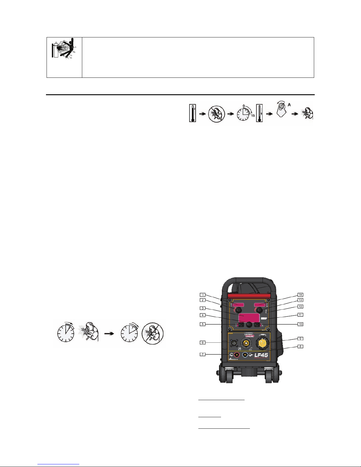
Figure 1.
1. Left Display Window: Shows Wire Feed Speed or
Amperage.
2. Left Knob: Adjusts values in left display.
3. MSP4 Display Window: Shows detailed welding
and diagnostic information.
Page 6
English English3
4. Set Knob: Changes the value on the MSP4 display.
5. Left Button: Changes the MSP4 display to show the
Weld Mode or Arc Control.
6. 12-pin Connector: Connector for a remote control
and a push-pull gun.
7. Water Cooling Line: Warm water from torch.
8. Water Cooling Line: Cool water to torch.
9. EURO Connector.
10. Right Button: Changes the MSP4 display to show
Start Options or End Options.
11. Set-Up: Lights when feeder is set-up.
12. Thermal: Lights when the drive overheats.
13. Right Knob: Adjusts values in the right display.
14. Right Display Window: Shows Voltage or Trim.
Figure 2.
1. Gas Connector: Connection for gas line.
2. 5-pin Connector: ArcLink connection to power
source.
3. Fast-Mate Adapter: Input power connection.
4 - 5. Quick Connect Couplings: If water cooled
torches are used, connect water lines from
water cooler here. Refer to torch and water
cooler guidelines for recommended cooling
liquid and flow rates.
Figure 3.
1. Wire Drive: 4-Roll wire drive compatible with 37mm
drive rolls.
2. Cold Inch / Gas Purge Switch: This switch enables
wire feeding or gas flow without turning on output
voltage.
3. Wire Spool Support: Maximum 15kg spools.
Accepts plastic, steel and fiber spools onto 51mm
spindle.
WARNING
The Linc Feed wire feeders must be used with the door
completely closed during welding.
Not use handle to move the Linc Feed during work.
Loading the Electrode Wire
Open the side cover of the machine.
Unscrew the fastening cap of the sleeve.
Load the spool with the wire on the sleeve such that the
spool turns clockwise when the wire is fed into the wire
feeder.
Make sure that the spool locating pin goes into the fitting
hole on the spool.
Screw in the fastening cap of the sleeve.
Put on the wire roll using the correct groove
corresponding to the wire diameter.
Free the end of the wire and cut off the bent end making
sure it has no burr.
WARNING
Sharp end of the wire can hurt.
Rotate the wire spool clockwise and thread the end of
the wire into the wire feeder as far as the Euro socket.
Adjust force of pressure roll of the wire feeder properly.
Adjustments of Brake Torque of Sleeve
To avoid spontaneous unrolling of the welding wire the
sleeve is fitted with a brake.
Adjustment is carried by rotation of its screw M10, which
is placed inside of the sleeve frame after unscrewing the
fastening cap of the sleeve.
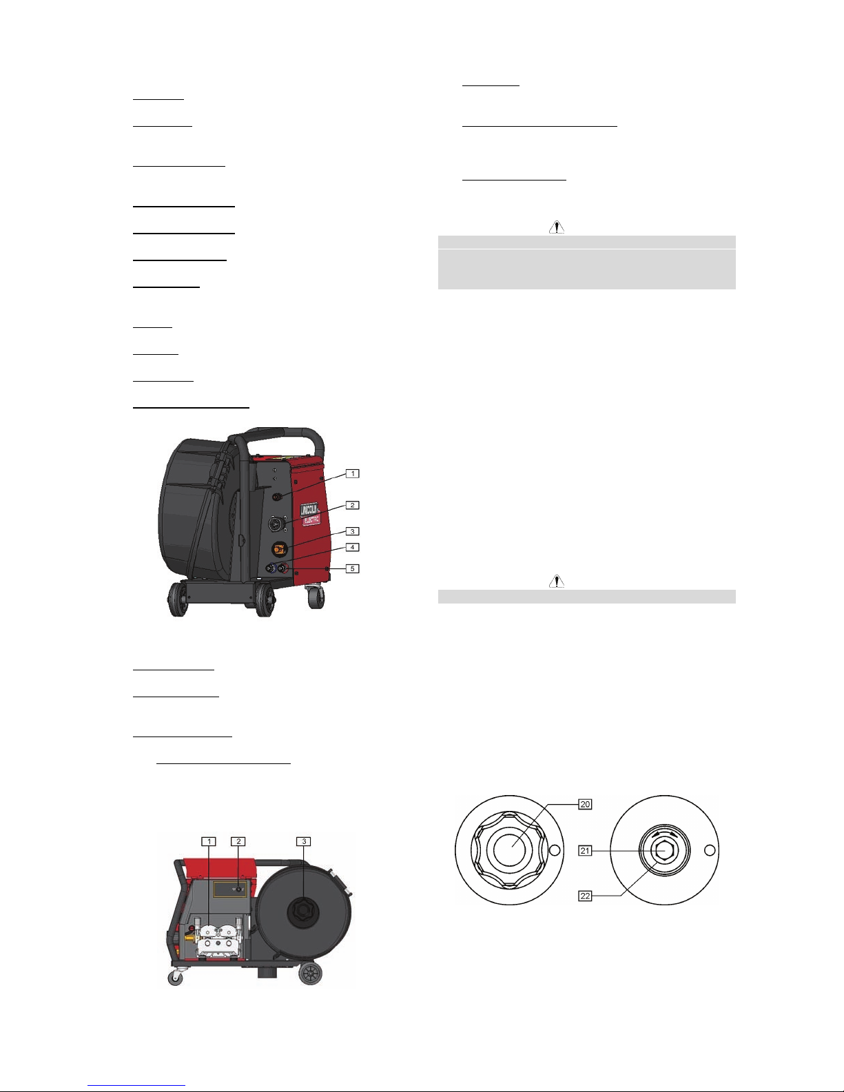
Figure 4.
20. Fastening cap.
21. Adjusting screw M10.
22. Pressing spring.
Turning the screw M10 clockwise increases the spring
tension and you can increase the brake torque.
Page 7
English English4
Turning the screw M10 counterclockwise decreases the
spring tension and you can decrease the brake torque.
After finishing of adjustment, you should screw in the
fastening cap again.
Adjusting of Pressure Roll Force
WARNING
ELECTRIC SHOCK can kill.
Turn the input power OFF at the welding power
source before installation or changing drive rolls
and/or guides.
Do not touch electrically live parts.
When inching with the gun trigger, electrode and
drive mechanism are "hot" to work and ground and
could remain energized several seconds after the
gun trigger is released.
Do not operate with covers, panels or guards
removed or open.
Only qualified personnel should perform
maintenance work.
Pressure force is adjusted by turning the adjustment nut
clockwise to increase force, counterclockwise to
decrease force.
The pressure arm controls the amount of force the drive
rolls exert on the wire. Proper adjustment of pressure
arm gives the best welding performance. Set the
pressure arm as follows:
Aluminum wires: between 1 and 3
Cored wires: between 3 and 4
Steel, Stainless wires: between 4 and 6
WARNING
If the roll pressure is too low the roll will slide on the wire.
If the roll pressure is set too high the wire may be
deformed, which will cause feeding problems in the
welding gun. The pressure force should be set properly.
Decrease the pressure force slowly until the wire just
begins to slide on the drive roll and then increase the
force slightly by turning of the adjustment nut by one
turn.
Inserting Electrode Wire into Welding
Torch
Connect the proper welding torch to the Euro socket, the
rated parameters of the torch and of the welding source
shall match.
Remove the gas diffuser and contact tip from the
welding torch.
Switch the Cold Inch / Gas Purge switch [2] (see Figure
3.) in the position "Cold Inch" and keep in this position
until the electrode wire leaves the contact tip of the
welding torch.
Set the wire feeding speed in the position of about
10m/min by the Left Knob [2] (see Figure 1.).
WARNING
Take precaution to keep eyes and hands away from the
end of the torch while feeding wire.
WARNING
Once the wire has finished feeding through the welding
gun turn the machine “OFF“ before replacing to contact
tip and gas diffuser.
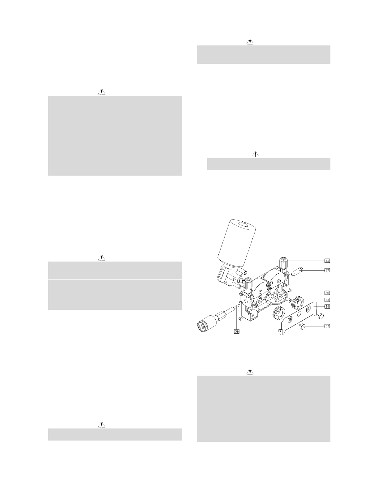
Changing Driving Rolls
The machine is equipped with drive rolls for the wire of
1.0 and 1.2mm (factory default). For others wire sizes,
is available the proper drive rolls kit (see chapter
Accessories for ordering the desired kit). Below is the
drive rolls replacement procedure:
Switch off the machine.
Release the pressure roll lever [32].
Unscrew the fastening cap [33].
Open the protection cover [34].
Change the drive rolls [35] with the compatible ones
corresponding to the used wire.
WARNING
For wires with the diameter greater than 1.6mm, the
following parts are to be changed:
The guide tube of the feeding console [36] and
[37].
The guide tube of the Euro socket [38].
Replace and tighten the protection cover [34] to the
drive rolls.
Screw the protection cover by fastening screws [33].
Figure 5.
Making A Weld With Waveform
Technology Power Sources
WARNING
The serviceability of a product or structure utilizing the
welding programs is and must be the sole responsibility
of the builder/user. Many variables beyond the control of
The Lincoln Electric Company affect the results obtained
in applying these programs. These variables include,
but are not limited to welding procedure, plate chemistr y
and temperature, weldment design, fabrication methods
and service requirements. The available range of a
welding program may not be suitable for all applications,
and the build/user is and must be solely responsible for
welding program selection.
Page 8

English English5
The steps for operating the Power Source will vary
depending upon the user interface of the welding
system. The flexibility of the Power Source lets the user
customize operation for the best performance.
First, consider the desired welding process and the
part to be welded. Choose an electrode material,
diameter, shielding gas and process (GMAW,
SMAW, etc.)
Second, find the program in the welding software
that best matches the desired welding process. The
standard software shipped with the Power Source
encompasses a wide range of common processes
and will meet most needs. All adjustments are
made on the user interface. Because of the
different configuration options your system may not
have all of the following adjustments.
Regardless of availability, all controls are described
below.
SMAW (Stick) Welding
SMAW is most often used for outdoor construction, pipe
welding and general repairs. The wire feeder speed
controls Amperage, Output Control and Arc Force.
During SMAW welding, the wire feeder sets the weld
parameters and the wire drive remains idle. The “Volts””Trim” control is used to turn the power Source Output
ON or OFF (See Figure below)
O F F
5
S t i c k
C C S t i c k
Figure 6. SMAW (Stick) Welding Display
GTAW (TIG) Welding
The SpeedTec is excellent for Touch Start TIG welding.
The wire feeder speed controls Amperage. During
SMAW welding, the wire feeder sets the weld
parameters and the wire drive remains idle. The “Volts””Trim” control is used to turn the power Source Output
ON or OFF (See Figure below)
O F F
5
TIG
3
Figure 7. GTAW (TIG) Welding Display
GMAW (MIG) Synergic Welding Display
Synergic CV programs feature an ideal voltage best
suited for most procedures. Use this voltage as a
starting point and adjust if needed for personal
preferences.
1 7. 5
1. 2 7
S t e e l 1. 0 mm
C V C O 2
1 0
Figure 8. GMAW (MIG) Synergic Welding Display
Synergic CV Voltage Display
When the voltage knob is rotated, the display will show
an upper or lower bar indicating if the voltage is above or
below the ideal voltage.
Preset voltage above ideal voltage
(upper bar displayed)
Preset voltage at ideal voltage
(no bar displayed)
Preset voltage below ideal voltage
(lower bar displayed)
MSP4 Operation
Left Button:
Weld Mode
Wire Size
Electrode Gas
0.8 1.0 1.2 1.6
Steel CO2 93 10 20 24
Steel Ar(mix) 94 11 21 25
Stainless Ar(mix) 61 31 41 ---
Stainless Ar/He/CO2 63 33 43
Alu 4043 Ar --- 148 71 --Alu 5356 Ar --- 151 75 77
FluxCore Gas Shld 155
Arc Con t rol
Effect Range Description
Pinch Effect
(-10.0 to +10.0)
Pinch controls the arc characteristics
when short-arc welding.
Page 9

English English6
Memory
Effect Range Description
Job1..Job8 Allows memorizing the selected weld
mode.
Right Button:
Start Options
Effect/Range Description
Preflow Time
0-25.0 seconds
Adjusts the time that shielding gas
flows after the trigger is pulled and prior
to feeding.
Run-in WFS
Off, 1 to 12 m/min
Run-in sets the wire feed speed from
the time the trigger is pulled until an arc
is established.
Start Procedure The Start Procedure controls the WFS,
Volts at a specified time at the
beginning of the weld. During the start
time, the machine will ramp up or down
from the Start Procedure to the preset
Welding Procedure.
End options
Effect/Range Description
Spot Timer
0 to 120.0 seconds
Adjust the time welding will continue even
if the trigger is still pulled. This option has
no effect in 4-Step Trigger Mode.
Postflow Time
0 to 25.0 seconds
Adjusts the time that shielding gas flows
after the welding output turns off.
Burnback The burnback time is the amount of time
that the weld output continues after the
wire stops feeding. It prevents the wire
from sticking in the puddle and prepares
the end of the wire for the next arc start.
Crater Procedure Crater Procedure controls the WFS and
volts for a specified time at the end of the
weld after the trigger is released. During
the Crater time, the machine will ramp up
or down from the Weld Procedure to the
Crater Procedure.
2/4 Step Mode
Effect Range Description
2-Step, 4-Step Selects between 2-Step and 4-Step mode
of weld.
2- STEP 4- STEP- Trigger Operation
The 2-Step - 4-Step switch changes the function of the
gun trigger. 2-Step trigger operation switches the
welding output ON-OFF in direct response to the trigger.
4-Step trigger operation provides 'trigger interlock'
capability and gives the ability to control the amount of
time spent in the arc start and arc crater steps. Press
the push button on the case front to toggle between 2Step and 4-Step operation. The 2-Step, 4-Step trigger
has no effect when welding with SMAW or CAG
procedures.
2-Step Trigger
2-Step trigger operation is the most common. When the
gun trigger is pulled, the welding system (power source
and wire feeder) cycles through the arc starting
sequence and into the main welding parameters. The
welding system will continue to weld as long as the gun
trigger is activated. Once the trigger is released, the
welding system cycles through the arc ending steps.
4-Step Trigger
4-Step trigger operation gives the welder additional
control in the welding sequence. 4-Step trigger allows
the welder to choose the arc start, weld and arc end
time. It may also be set-up to work as a trigger interlock.
Example 1:
2 Step Trigger: Simple operation
The simplest trigger operation occurs with a 2 Step
trigger and the Start, Crater and Burnback functions all
set to OFF (See Figure Below). For this sequence:
PREFLOW: Shielding gas begins to flow
immediately when the gun trigger is pulled.
RUN-IN: After preflow time expires, the power
source regulates to the welding output and wire is
advanced towards the work piece at the Run-In
WFS. If an arc is not established within 1.5
seconds, the wire feed speed will jump to the
welding wire feed speed.
WELD: The power source output and the wire feed
speed continue at the weld settings for as long as
the trigger is pulled.
POSTFLOW: As soon as the trigger is released,
the power source output and the wire feed speed
are turned OFF. Shielding gas continues until the
post flow timer expires.
On
Off
Off
Off
Weld
Weld
Run-in
Shielding
Gas
Power
Source
Output
WFS
Idle Preflow Run-in Weld Postflow Idle
Trigger Pull led
Arc Establi shed
Trigger Released
2 Step Trigger
Start = Off
Crater = Off
Burnback = Off
1.5s max
Example 2:
2 Step Trigger: Improved Arc Start and Arc End.
Tailoring the arc start and arc end is a common method
for reducing spatter and improving weld quality. This
can be accomplished with the Start and Burnback
functions set to a desired values and Crater set to OFF
(See Figure Below). For this sequence:
PREFLOW: Shielding gas begins to flow
immediately when the gun trigger is pulled.
RUN-IN: After preflow time expires, the power
source regulates to the start output and wire is
advanced towards the work piece at the Run-In
WFS. If an arc is not established within 1.5
seconds, the power source output and wire feed
speed skips to the weld settings.
START & UPSLOPE: Once the wire touches the
work and an arc is established, both the machine
output and the wire feed speed ramp to the weld
settings throughout the start time. The time period
of ramping from the start settings to the weld
settings is called UPSLOPE.
WELD: After upslope, the power source output and
the wire feed speed continue at the weld settings.
BURNBACK: As soon as the trigger is released,
the wire feed speed is turned OFF and the machine
output continues for the burnback time.
POSTFLOW: Next, the machine output is turned
OFF and shielding gas continues until the post flow
timer expires.
Page 10

English English7
On
Off
Off
Off
Weld
Weld
Run-in
Shielding
Gas
Power
Source
Output
WFS
Idle Preflow Strike Weld Postflow Idle
Trigger Pullled
Arc Establi shed
Trigger Released
2 Step Trigger
Start = On
Crater = Off
Burnback = On
1.5s max
Upslope Burnback
Start
Burnback T.
Start T.
Example 3:
2 Step Trigger: Customized Arc Start, Crater and Arc
End.
Sometimes it is advantageous to set specific arc start,
crater and arc ending parameters for the ideal weld.
Many times when welding aluminum crater control is
necessary to make a good weld. This is done by setting
Start, Crater and Burnback functions to desired values
(See Figure Below). For this sequence:
PREFLOW: Shielding gas begins to flow
immediately when the gun trigger is pulled.
RUN-IN: After preflow time expires, the power
source regulates to the start output and wire is
advanced towards the work piece at the Run-In
WFS. If an arc is not established within 1.5
seconds, the power source output and wire feed
speed skips to the weld settings.
START & UPSLOPE: Once the wire touches the
work and an arc is established, both the machine
output and the wire feed speed ramp to the weld
settings throughout the start time. The time period
of ramping from the start settings to the weld
settings is called UPSLOPE.
WELD: After upslope, the power source output and
the wire feed speed continue at the weld settings.
CRATER & DOWNSLOPE: As soon as the trigger
is released, the wire feed speed and power source
output ramp to the crater settings throughout the
crater time. The time period of ramping from the
weld settings to the crater settings is called
DOWNSLOPE.
BURNBACK: After the crater time expires, the wire
feed speed is turned OFF and the machine output
continues for the burnback time.
POSTFLOW: Next, the machine output is turned
OFF and shielding gas continues until the post flow
timer expires.
On
Off
Off
Off
Weld
Weld
Run-in
Shielding
Gas
Power
Source
Output
WFS
Idle Preflow Strike Weld Postflow Idle
Trigger Pullled
Arc Established
Trigger Released
2 Step Trigger
Start = On
Crater =On
Burnback = On
1.5s max
Upslope Burnback
Start
Burnback T.
Start T.
Down
slope
Crater
Crater T.
Crater
Example 4:
4 Step Trigger: Trigger Interlock
The 4 step trigger can be configured as a trigger
interlock. Trigger interlock adds to the welder’s comfort
when making long welds by allowing the trigger to be
released after an initial trigger pull. Welding stops when
the trigger is pulled a second time and then released, or
if the arc is interrupted (See Figure Below). For this
sequence:
PREFLOW: Shielding gas begins to flow
immediately when the gun trigger is pulled.
RUN-IN: After preflow time expires, the power
source regulates to the welding output and wire is
advanced towards the work piece at the Run-In
WFS. If an arc is not established within 1.5
seconds, the wire feed speed will jump to the
welding wire feed speed.
WELD: The power source output and the wire feed
speed continue at the weld settings. Welding
continues when the trigger is pulled a second time.
POSTFLOW: As soon as the trigger is released for
the second time, the power source output and the
wire feed speed are turned OFF. Shielding gas
flows until the post flow timer expires.
On
Off
Off
Off
Weld
Weld
Run-in
Shielding
Gas
Power
Source
Output
WFS
Idle Preflow Strike Weld Postflow Idle
Trigger Pullled
Arc Established
Trigger Released
4 Step Trigger
Start = Off
Crater =Off
Burnback = Off
1.5s max
Burnback
Start
Crater
Crater
Trigger Pullled
Trigger Released
Page 11

English English8
Example 5:
4 Step Trigger: Manual control of Start and Crater
times with Burnback ON
The 4 step trigger sequence gives the most flexibility
when the Start, Crater and Burnback functions are
active. This is a popular choice when welding aluminum
because extra heat may be needed during Start and less
heat desired during crater. With 4 step trigger, the
welder chooses the amount of time to weld at the Start,
Weld and Crater settings by using the gun trigger.
Burnback reduces the occurrence of wire to sticking into
the weld pool at the end of a weld and conditions the
end of the wire for the next arc start ( See Figure Below).
For this sequence:
PREFLOW: Shielding gas begins to flow
immediately when the gun trigger is pulled.
RUN-IN: After preflow time expires, the power
source regulates to the start output and wire is
advanced towards the work piece at the run-in
WFS. If an arc is not established within 1.5
seconds, the power source output and wire feed
speed skips to the weld settings.
START: The power source welds at the start WFS
and voltage until the trigger is released.
UPSLOPE: During upslope, the power source
output and the wire feed speed ramp to the weld
settings throughout the start time. The time period
of ramping from the start settings to the weld
settings is called UPSLOPE.
WELD: After upslope, the power source output and
the wire feed speed continue at the weld settings.
DOWNSLOPE: As soon as the trigger is released,
the wire feed speed and power source output ramp
to the crater settings throughout the crater time.
The time period of ramping from the weld settings to
the crater settings is called DOWNSLOPE.
CRATER: During CRATER, the power source
continues to supply output at the crater WFS and
voltage.
BURNBACK: When the trigger is released, the
wire feed speed is turned OFF and the machine
output continues for the burnback time.
POSTFLOW: Next, the machine output is turned
OFF and shielding gas continues until the post flow
timer expires.
On
Off
Off
Off
Weld
Weld
Run-in
Shielding
Gas
Power
Source
Output
WFS
Idle PreflowStri ke Weld
Postflow
Idle
Trigger Pullled
Arc Establi shed
Trigger Released
4 Step Trigger
Start = On
Crater =On
Burnback = On
1.5s max
Burnback
Start
Burnback T.
Start T.
Crater
Crater T.
Crater
Trigger Pullled
Trigger Rel eased
Start Upslope Downslope Crater
Start
SET-UP FEATURES MENU
The Setup Menu gives access to the set-up
configuration. Stored in the set-up configuration are
user parameters that generally need to be set only at
installation. The parameters are grouped as follows:
P.1 through P.99 Unsecured Parameters (always
adjustable).
P.101 through P.199 Diagnostic Parameters
(always read only).
P.501 through P.599 Secured Parameters
(accessible only though a p.c. or palm application).
To access the set-up menu, press the right and left
buttons of the MSP4 panel simultaneously. Note that
the set-up menu cannot be accessed if the system is
welding, or if there is a fault (The status LED is not solid
green). Change the value of the blinking parameter by
rotating the SET knob.
After changing a parameter it is necessary to press the
right hand button to save the new setting. Pressing the
left button will cancel the change. To exit the set-up
menu at any time, press the right and left buttons of the
MSP4 panel simultaneously. Alternately, 1 minute of
inactivity will also exit the setup menu.
Unsecured Parameters.
P.0 Press the left button to exit the set-up menu.
P.1 WFS units
Metric = m/min wire feed speed units
English = in/min wire feed speed units (default)
P.2 Arc Display Mode
Amps = The left display shows Amperage while
welding. (default)
WFS = The left display shows Wire Feed Speed
while welding.
P.4 Trigger Memory Recall
Enable = Selecting memories 2 through 6 with quick
trigger pulls is enabled when the optional dual
procedure/memory panel is installed. To recall a
memory with the gun trigger, quickly pull and
release the trigger the number of times that
correspond to the memory number. For example, to
recall memory 3, quickly pull and release the trigger
3 times. Trigger memory recall can only be
performed when the system is not welding.
Disable = Memory selection is performed only by
the buttons on the optional dual procedure/memory
panel (default).
P.5 Trigger Procedure Change
Quick Trigger = Allows switching between
Procedure A and procedure B while welding. The
optional dual procedure/memory panel is required.
To operate:
Select procedure “GUN” on the memory panel.
Start the weld by pulling the gun trigger. The
system will weld with procedure A settings.
While welding, quickly release and then pull the
gun trigger. The system will switch to
procedure B settings.
Release the trigger to stop welding. When the
next weld is made, the system will start again
with procedure A.
Integral TrigProc = Use Integral Trigger + Procedure
Page 12

English English9
Switch when using a Lincoln Dual Schedule gun.
When in 2-step, the system operates identical to the
External Switch selection. To operate in 4-step:
Select procedure “GUN” on the memory panel.
Start the weld by pulling the gun trigger. The
system will weld with procedure A settings.
While welding, quickly release and then pull the
gun trigger. The system will switch to
procedure B settings.
Release the trigger to stop welding. When the
next weld is made, the system will start again
with procedure A.
External Switch = Dual Procedure selection may
only be performed by the memory panel button or a
dual procedure gun (default).
P.6 Push Pull Gun, Stall Factor Adjustment
The stall factor controls the stall torque of the push
motor when using a push-pull gun. The wire feeder is
factory set to not stall unless there is a large resistance
to feeding wire. The stall factor can be reduced to stall
more easily and possibly prevent bird nesting. However,
low stall factors can cause motor stalling while welding
which results in the wire burning back to the tip. If you
are experiencing bird nests, check for other feeding
problems before adjusting the stall factor. Default value
for the stall factor is 75, with a range of 5 - 100. To
change the stall factor:
Use the VOLTS/TRIM knob to adjust the stall factor.
Increasing the stall factor raises the motor torque
and decreasing the stall factor lowers the motor
torque. Do not increase the stall factor more than
necessary. A high stall factor may increase the
occurrence of bird nesting and a low stall factor may
cause the wire to burn back to the tip.
Press the right hand button to save the new setting.
P.7 Push Pull Gun, Gun Offset Adjustment
The pushpull gun offset calibration adjusts the wire feed
speed calibration of the pull motor. The procedure
should only be performed when other possible
corrections do not solve the push-pull feeding problems.
A rpm meter is required to perform the pull gun motor
offset calibration. To perform the calibration procedure:
Release the pressure arm on both the pull and push
wire drives.
Set the wire feed speed to 200 rpm.
Remove wire from the pull wire drive.
Hold the rpm meter to the drive roll in the pull gun.
Pull the trigger on the push-pull gun.
Measure the rpm of the pull motor. The rpm should
be between 115 and 125 rpm. If necessary,
decrease the calibration setting to slow the pull
motor, or increase the calibration setting to speed
up the motor. The calibration range is -30 to +30,
with 0 as the default value.
Press the right hand button to save the new setting.
P.8 TIG Gas Control (Two Settings)
1. "Valve (manual)", the internal solenoid will not
actuate while TIG welding, gas flow is manually
controlled by an external valve.
2. "Solenoid (auto)", the internal gas solenoid will
turn on and off automatically while TIG welding as
follows:
Preflow time will not be accessible from the
MSP4.
Postflow time will be available in the MSP4
"End Options" and have a range of OFF to 10.0
seconds.
The postflow time value is maintained when
switching between MIG and TIG modes.
When machine output on/off is controlled via
the right encoder, gas flow will not start until the
tungsten touches, the work piece, gas flow will
stop after the postflow time when the arc is
broken.
When machine output on/off is controlled via an
arc start switch or foot Amptrol, gas will begin
flo
wing when the output is turned on and stop
flowing after the postflow period after the output
is turned off.
P.9 Crater Delay
Use the crater delay to skip the Crater sequence when
making short tack welds. If the trigger is released before
the Crater Delay Timer ends, then the Crater sequence
is skipped. If the trigger is released afterwards, the
Crater sequence functions normally.
Values = OFF to 10.0 seconds (OFF is default).
P.11 Set Timers
This menu is used to adjust timer values for Upslope,
Downslope and Restrike. Press the right button to enter
the Set Timer menu. Rotate the knob to select the timer
to adjust and then press the right button. Adjust the
value of the timer by rotating the knob. Press the left
MSP4 button to set the value and exit. Continue to
adjust other timers as necessary, and then press the left
button to exit the Set Timer menu.
P.12 Travel Options
This menu is used to change the travel options for a
travel carriage, including starting and ending functions.
The right MSP4 button to enter the Travel Options menu
and rotate the encoder to select either starting or ending
options. Press the right MSP4 button to select the
option. Press the left MSP4 button to set the value and
exit. Rotate the encoder to select other options, or press
the left MSP4 button to exit the menu.
P.13 Adjust Arc Force
Use this menu to adjust Arc Force values for Start, Weld
and Crater. Press the right MSP4 button to enter the
menu and rotate the knob to choose either Start, Weld or
Crater. Press the right MSP4 button and then rotate the
knob to the desired value. Press the left MSP4 button to
set the value and exit. Continue to adjust Arc Force for
other states, and then press the left MSP4 button to exit
the menu.
P.14 Reset Consumable Weight
This parameter only appears with systems using
Production Monitoring. Use this parameter to reset the
initial weight of the consumable package.
P.16 Push-Pull Gun Knob
Gun Pot Enabled = The wire feed speed is always
controlled by the potentiometer on the push-pull gun
(default).
Gun Pot Disabled = The wire feed speed is always
controlled by the left display knob on the feeder.
Gun Pot Proc A = When in procedure A, the wire
feed speed is set by the push-pull gun
potentiometer. When in procedure B, the wire feed
speed is set by the left display knob on the feeder.
P.25 Joystick Configuration
The new analog and digital gun controls have a joystick
Page 13

English English10
to allow the user to change various weld settings at the
gun rather than having to go to the user interface. P.25
can be used to change the behavior of the joystick. In all
configurations, the up and down joystick positions will
adjust the wire feed speed, while welding and while not
welding. P.25 is used to reconfigure the behavior of the
left and right joystick positions.
When P.25 is set to “Trim/Volts/etc.”, the left and
right joystick positions will adjust Arc Length Trim,
Arc Voltage, Power or STT Background Current
based on the selected weld mode. For example,
when a non-synergic STT weld mode is selected,
the left and right joystick positions will adjust
Background Current. When a Power mode is
selected, the left and right joystick positions will
adjust the Power (kW).
When P.25 is set to “Memory+Trim/etc.”, the left
and right joystick positions will select a user memory
while not welding and adjust
Trim/Voltage/Power/STT Background Current while
welding.
When P.25 is set to “Procedure A/B”, the left and
right joystick positions will be used to select
procedure A and B, while welding and while not
welding. The left joystick position selects procedure
A, the right joystick position selects procedure B.
Diagnostic Parameters
P.80 Sense from Studs
Use this parameter for diagnostic purposes only. When
power is cycled, P.80 is automatically reset to False.
False = Sensing for the electrode (67) and work (21)
is determined by the DIP switches of the system.
True = Sensing for the electrode (67) and work (21)
is measured at the studs of the power source and
the DIP switch settings are overridden.
P.99 Show Test Modes
Many weld tables include special modes for testing and
servicing the welding system. Set this parameter to YES
to show all test modes. When the power source is
turned off, the Show Test Modes parameter
automatically reverts back to "NO".
P.100 View Diagnostics
Diagnostics are only used for servicing the Power Wave
system.
Yes = Shows P.101 through P.500 in the SETUP
menu.
No = Only P.0 through P.100 are shown in the
SETUP menu.
P.101 Event Logs
Press the right MSP4 button to view the Event Logs.
Rotate the encoder to select the object to read and then
press the right MSP4 button. Various software
information will appear about key system events. Press
the left MSP4 button to exit.
P.102 Fatal Logs
Press the right MSP4 button to view the Fatal Logs.
Rotate the encoder to select the module to read and
then press the right MSP4 button. Various software
information will appear about critical module actions.
Press the left MSP4 button to exit.
P.103 Software Version
Press the right MSP4 button to view the software loaded
into each module (p.c. board). Rotate the encoder to
select the module to read and then press the right MSP4
button. The panel will display the main software version
loaded into the module. Press the left MSP4 button to
exit.
P.104 Hardware Version
Press the right MSP4 button to view the hardware
version of each module (p.c. board). Rotate the encoder
to select the module to read and then press the right
MSP4 button. The panel will display the main hardware
version loaded into the module. Press the left MSP4
button to exit.
P.105 Welding Software
Press the right MSP4 button to view the welding
software version inside the power source. Press the left
MSP4 button to exit.
P.106 Ethernet IP Address
Press the right MSP4 button to view the IP address of
the Ethernet board. If no Ethernet Board is installed, the
display shows "No Enet Found". Press the left MSP4
button to exit.
P.107 Power Source
Press the right MSP4 button to view the type of power
source connected to the control box. Press the left
MSP4 button to exit.
Maintenance
WARNING
For any maintenance or repair operations it is
recommended to contact the nearest technical service
center or Lincoln Electric. Maintenance or repairs
performed by unauthorized service centers or personnel
will null and void the manufacturers warranty.
The frequency of the maintenance operations may vary
in accordance with the working environment where the
machine is placed.
Any noticeable damage should be reported immediately.
Routine maintenance
Check condition of insulation and connections of the
work cables and input power supply cable.
Remove the spatters from the welding gun nozzle.
Spatters could interfere with the shielding gas flow
to the arc.
Check the welding gun condition: replace it, if
necessary.
Check condition and operation of the cooling fan.
Keep clean its airflow slots.
Periodic maintenance
Perform the routine maintenance and, in addition:
Keep clean the machine. Using a dry ( and low
pressure) airflow, remove the dust from the external
case and from inside of the cabinet.
Check condition of all connections and change if
necessary.
Check and tighten all screws.
WARNING
Mains supply network must be disconnected from the
machine before each maintenance and service. After
each repair, perform proper tests to ensure safety.
Page 14

English English11
Electromagnetic Compatibility (EMC)
11/04
This machine has been designed in accordance with all relevant directives and standards. However, it may still generate
electromagnetic disturbances that can affect other systems like telecommunications (telephone, radio, and television) or
other safety systems. These disturbances can cause safety problems in the affected systems. Read and understand
this section to eliminate or reduce the amount of electromagnetic disturbance generated by this machine.
This machine has been designed to operate in an industrial area. To operate in a domestic area it is
necessary to observe particular precautions to eliminate possible electromagnetic disturbances. The
operator must install and operate this equipment as described in this manual. If any electromagnetic
disturbances are detected the operator must put in place corrective actions to eliminate these disturbances
with, if necessary, assistance from Lincoln Electric.
Before installing the machine, the operator must check the work area for any devices that may malfunction because of
electromagnetic disturbances. Consider the following.
Input and output cables, control cables, and telephone cables that are in or adjacent to the work area and the
machine.
Radio and/or television transmitters and receivers. Computers or computer controlled equipment.
Safety and control equipment for industrial processes. Equipment for calibration and measurement.
Personal medical devices like pacemakers and hearing aids.
Check the electromagnetic immunity for equipment operating in or near the work area. The operator must be sure
that all equipment in the area is compatible. This may require additional protection measures.
The dimensions of the work area to consider will depend on the construction of the area and other activities that are
taking place.
Consider the following guidelines to reduce electromagnetic emissions from the machine.
Connect the machine to the input supply according to this manual. If disturbances occur if may be necessary to take
additional precautions such as filtering the input supply.
The output cables should be kept as short as possible and should be positioned together. If possible connect the
work piece to ground in order to reduce the electromagnetic emissions. The operator must check that connecting
the work piece to ground does not cause problems or unsafe operating conditions for personnel and equipment.
Shielding of cables in the work area can reduce electromagnetic emissions. This may be necessary for special
applications.
Technical Specifications
INPUT VOLTAGE WIRE FEED SPEED
34-44 Vdc 0.75-22 m/min
RATED OUTPUT AT 40°C
Duty Cycle
(based on a 10 min. period)
100%
60%
Output Current
385 A
500 A
OUTPUT RANGE
Welding Current Range
5-500 A
Maximum Open Circuit Voltage
113 Vdc or Vac peak
WIRE SIZES (mm)
Solid wires
0.6 to 1.6
Cored wires
1.0 to 2.0
Aluminium wires
1.0 to 1.6
PHYSICAL DIMENSIONS
Height
440 mm
Width
270 mm
Length
636 mm
Weight
17 Kg
Operating Temperature
–10°C to +40°C
Storage Temperature
-25°C to +55°C
WEEE
07/06
English
Do not dispose of electrical equipment together with normal waste!
In observance of European Directive 2002/96/EC on Waste Electrical and Electronic Equipment (WEEE)
and its implementation in accordance with national law, electrical equipment that has reached the end of its
life must be collected separately and returned to an environmentally compatible recycling facility. As the
owner of the equipment, you should get information on approved collection systems from our local
representative.
By applying this European Directive you will protect the environment and human health!
Page 15

English English12
Spare Parts
12/05
Part List reading instructions
Do not use this part list for a machine if its code number is not listed. Contact the Lincoln Electric Service
Department for any code number not listed.
Use the illustration of assembly page and the table below to determine where the part is located for your particular
code machine.
Use only the parts marked "X" in the column under the heading number called for in the assembly page (# indicate
a change in this printing).
First, read the Part List reading instructions above, then refer to the "Spare Part" manual supplied with the machine, that
contains a picture-descriptive part number cross-reference.
Electrical Schematic
Refer to the "Spare Part" manual supplied with the machine.
Accessories
K10349-PG-xM Source wire/feeder cable (gas). Available in 5, 10,15, 20, 25 or 30m.
K10349-PGW-xM Source wire/feeder cable (gas and water). Available in 5, 10,15, 20, 25 or 30m.
K10158 Plastic adaptor for 15-kg coils (delivered as standard).
K10343 Innershield torch adaptor.
Drive rolls and guide tubes 2 driven rolls
KP14017-0.8
KP14017-1.0
KP14017-1.2
KP14017-1.6
Solid wires:
0,6-0,8mm
0,8-1,0mm
1,0-1,2mm
1,2-1,6mm
KP14017-1.6R
KP14017-2.4R
Cored wires:
1.0-1.6mm
1.6-2.4mm
KP14017-1.2A
KP14017-1.6A
Aluminum wires:
1,0-1,2mm
1,2-1,6mm
Page 16

Italiano ItalianoI
Dichiarazione di conformità
Lincoln Electric Bester Sp. z.o.o.
Dichiara che il generatore per saldatura tipo:
LINC FEED 45
è conforme alle seguenti direttive:
2006/95/CEE, 2004/108/CEE
ed è stato progettato in conformità alle seguenti
norme:
EN 60974-1, EN60974-5, EN 60974-10
(2009)
Paweł Lipiński
Operations Director
Lincoln Electric Bester Sp. z.o.o., ul. Jana III Sobieskiego 19A, 58-260 Bielawa, Poland
12/05
Page 17

Suomi Suomi12
Varusteet
K10349-PG-xM Välikaapeli (kaasu), saatavissa 5, 10, 15 ja 30 m:n pituisena.
K10349-PGW-xM Välikaapeli (kaasu, vesi), saatavissa 5, 10, 15, 20, 25 ja 30 m:n pituisena.
K10158 Muoviadapteri 15 kg:n keloille.
K10343 Innershield poltin adapteri.
Syöttöpyörät ja ohjausputket 2 - pyörävedolle
KP14017-0.8
KP14017-1.0
KP14017-1.2
KP14017-1.6
Umpilangat:
0,6-0,8mm
0,8-1,0mm
1,0-1,2mm
1,2-1,6mm
KP14017-1.6R
KP14017-2.4R
Täytelangat:
1.0-1.6mm
1.6-2.4mm
KP14017-1.2A
KP14017-1.6A
Alumiinilangat:
1,0-1,2mm
1,2-1,6mm
Page 18

Spare Parts - Electrical Schematic Spare Parts - Electrical Schematic1
Spare Parts
SP50194 Rev. 1
07/03
LINC FEED 45
ASSEMBLY
PAGE NAME
Machine Assembly
Wire Drive Assembly
CODE
NO.:
K NO.: FIGURE NO.: A-B C
50194 K14072-1 LINC FEED 45 1 1
Figure A
Figure B
Page 19

Spare Parts - Electrical Schematic Spare Parts - Electrical Schematic2
Figure A-B: Machine Assembly
Item Description Part Number QTY 1 2 3 4
1 LOCK 0654-610-004R 1 X
2 QUICK CONNECTOR MALE 0744-000-151R 1 X
3 QUICK CONNECTOR FEMALE 0744-000-152R 4 X
4 WIRE REEL SPINDLE 0744-000-192R 1 X
5 WIRE DRIVE 0744-000-241R 1 X
6 PLASTIC SHROUD ASSEMBLY 0749-901-003R 1 X
7 SOCKET MALE 1158-641-110R 1 X
8 GAS SOLENOID 0972-423-038R 1 X
9 FRONT WHEEL 1029-660-003R 2 X
10 REAR WHEEL 1029-660-081R 2 X
11 PROTECTION WASHER 0744-200-108R 1 X
12 SWITCH 1158-650-022R 1 X
13 PIVOT TOP PART 1361-598-180R 1 X
14 EURO SLEEVE 1361-599-708R 1 X
15 SLEEVE 1361-599-720R 4 X
16 RUBBER BUTTON 1373-182-005R 2 X
17 WARNING DECAL 2719-107-728R 1 X
18 BASE 2719-107-732R 1 X
19 PLASTIC CAP B11035-1 1 X
20 CONTROL PC BOARD R-6042-053-1R 1 X
21 UI PC BOARD R-6042-054-1R 1 X
22 KNOB 9ET13639-3R 3 X
23 WASHER C-1661-004-5R 2 X
24 DINSE SOCKET C-2986-001-3R 1 X
25 SLEEVE D-1869-033-3R 2 X
26 SOCKET D-2985-002-1R 1 X
27 HINGE D-3574-007-1R 2 X
28 LEFT PANEL R-1019-227-1R 1 X
29 STICKER R-0010-282-1R 1 X
30 NAME PLATE R-0010-284-1R 1 X
31 UI LABEL R-0010-285-1R 1 X
32 STICKER R-0010-290-1R 1 X
33 CONDUCTOR RAIL R-1010-039-1R 1 X
34 CONDUCTOR RAIL R-1010-040-1R 1 X
35 RIGHT PANEL R-1019-224-1R 1 X
36 DIVIDER R-1019-207-1/08R 1 X
37 AXLE R-2013-021-1R 1 X
38 ALU RING R-2013-032-1R 1 X
39 COUPLER R-2013-060-1R 1 X
40 FRAME R-3019-156-1/08R 1 X
41 COVER R-3019-162-1/02R 1 X
42 FRONT PANEL R-3019-168-1/08R 1 X
43 DIVIDER R-3019-169-1/08R 1 X
44 PLATE R-3019-170-1/08R 1 X
45 REMOTE SOCKET 1158-641-149R 1 X
46 HARNESS R-5041-171-1R 1 X
47 MOTOR R-8040-024-3R 1 X
48 EURO SOCKET R-8040-140-3R 1 X
49 MAGNETIC RING 0943-719-005R 1 X
50 TACHO CAP 0744-200-008R 1 X
51 HALL SENSOR 0943-719-008R 1 X
52 SUPPRESSION CHOKE R-5041-228-1R 1 X
Page 20

Spare Parts - Electrical Schematic Spare Parts - Electrical Schematic3
Figure C
Figure C: Wire Drive Assembly
Item Description Part Number QTY 1 2 3 4
1 FEED PLATE 0646-233-002R 1 X
2 FIXING ARM COMPL. 0646-233-015R 2 X
3 INLET GUIDE 0646-233-025R 1 X
4 AXIS PRESSURE ARM 0646-233-003R 2 X
5 SPRING PRESSURE ARM 0646-233-013R 2 X
6 PRESSURE ARM COMPL.L 0646-233-007R 1 X
7 INTERMEDIATE GUIDE 0646-233-023R 1 X
8 AXIS DRIVE ROLL 0646-233-020R 2 X
9 GEAR WHEEL ROLL 0646-231-090R 2 X
10 GEAR WHEEL MOTOR 0646-233-028R 1 X
11 FIXING CAP 0646-233-022R 2 X
12 METAL COVER 0646-233-027R 1 X
13 PRESSURE ARM COMPL.R 0646-233-005R 1 X
14 WIRE FEED MOTOR R-8040-024-3R 1 X
15 WOODRUFF KEY 0646-231-102R 1 X
Page 21

Spare Parts - Electrical Schematic Spare Parts - Electrical Schematic4
Electrical Schematic
LINC FEED 45
Page 22

Spare Parts - Electrical Schematic Spare Parts - Electrical Schematic5
WEEE
Recycle ST
Ref. Fe Al Cu Brass Boards Plastics
Liquid
Cristal
External
Electric
Cables Capacitors
Base Assembly 15 X
Bolt 22 X
Brake 25,26 X
Cover 2 X
Divider 17, 21 X
Euro Socket 12 X X
Front Panel 6 X
Knob 5 X
Left Side Panel 4 X
Motor 27 X X
P.C. Board 3 X
P.C. Board 11 X
Quick Coupling 9 X
Rail 1 X X
Control Socket 7, 31 X X
Right Side Panel 23 X
Rotary Bracket 14 X
Rubber Button 10 X
Gas Switch 30 X X X
Spool Cover 28 X
Switch 24 X X X
Top Panel 29 X
Washer 19, 20 X
Welding Socket 8 X X
Wheels 13,16 X X
Wire Feeder 18 X
Suppression choke 32 X
 Loading...