

Page 1

Multi-Weld
TM
350
Distribution Box, Welding Cable Connectors, Input Cables, Remote
Output Control, Undercarriage
K1735-1 Multi-Weld 350
SAE-400, Vantage 500, DC-655, DC-1000, DC-1500
• Independent arcs. Starting or stopping one Multi-Weld doesn’t
affect the welding of the others.
• The Multi-Weld 350 is capable of continuous operation at 350
amps in 122°F (50°C) air temperature.
• No control cables are needed. Single weld cable output from the
power source to one or several Multi-Weld 350s.
• Controls are located close to the operator for quick access.
• High efficiency design uses less than half the power of other
grid systems.
• Lincoln Chopper Technology™ for quality welds with
instant control of the arc for superior welding results.
• Constant voltage (CV) for MIG or flux-cored wire welding.
• Constant current (CC) for stick welding or arc gouging.
• Additional stick welding controls include hot start, arc force,
electrode type selection (E7018 and E6010).
•Arc gouging capability with a single Multi-Weld 350 and up to
5/16" (8.0mm) electrode, or with paralleled units for up to 700
amps of power using a 3/8" (9.5mm) electrode.
• Manufactured under a quality system certified to ISO 9001
requirements and ISO 14001 environmental standards.
• Three-year warranty on parts and labor.
MULTI-OPERATOR
Connect Several DC+ Welders to One Power Supply.
Stick MIG Flux-Cored Gouging
Processes (DC+ Processes Only)
Description
Output Input
80
VDC
Advantage Lincoln
Recommended General Options
Recommended Power Source Options
LN-15 Across-the-Arc, LN-25 Across-the-Arc
Recommended Wire Feeder Options
Order
The Multi-Weld 350 is a 350 amp, DC+, 100% duty cycle welder capable of
CV-wire, CC-stick or arc gouging. With its high efficiency, the Multi-Weld 350
offers an entirely new and better way to build large structures. This unique
system offers a cleaner, safer job site, and allows operators to have high
performance welding control right where they need it — at the arc.
Publication E5.302 3/05
Web Update 6/05
www.lincolnelectric.com
TECHNICAL SPECIFICATIONS
Input Current Dimensions Net
Product Product Input Rated DC+ Output at Rated DC Output H x W x D Weight
Name Number Volts Current/Voltage/Duty Cycle Output (80V DC) Range in. (mm) lbs. (kg)
80V DC 15 - 40 Volts
Multi-Weld K1735-1 (50 - 113 350A / 34V / 100% DC
+ 165A 30 - 350 Amps 11.6 x 10 x 21.5 59
350 Peak Range) Max. OCV: 78V (295 x 254 x 546) (27)
Page 2
[2][2]
13
4
5
6
7
8
9
10
11
12
2
Access Door Removed for Clarity
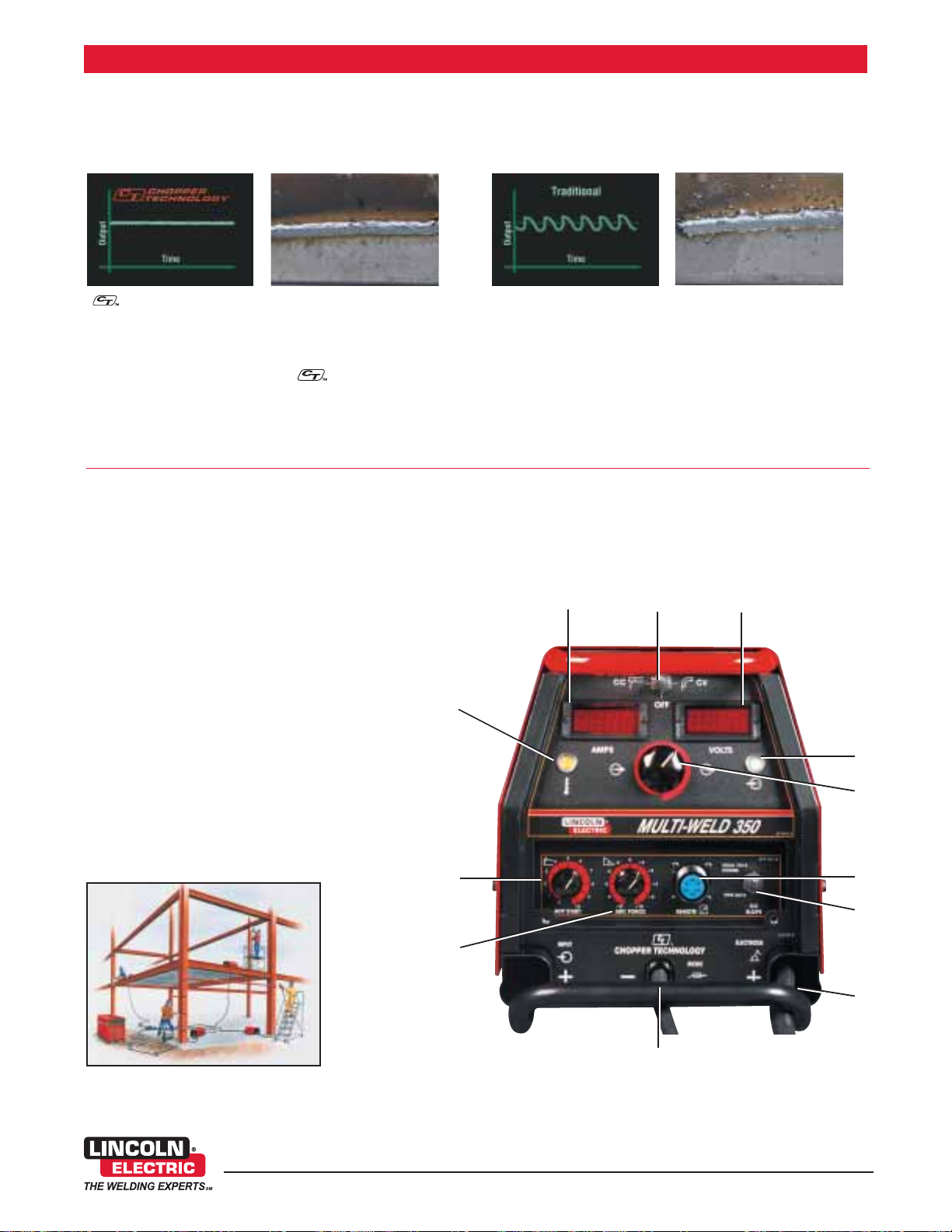
A CLOSER LOOK
1) Large, Easy to Read, Presettable Digital Amp Meter
2) Off/CC/CV Switch
3) Large, Easy to Read, Presettable Digital Volt Meter
4) Input Voltage OK Light
5) Large Control Knob for Gloved Hands
6) Remote Control Connection
7) Optimized Arc Switch for E7018 or E6010 Type Electrodes
8) “Pig Tail” Cables for Custom Quick Connectors. Front
and rear routings.
9) 10 ft. (3m) Work Clamp Lead
10) Arc Force Control
11) Hot Start Control For Fast and Easy Starts
12) Thermal Protection Trip Indicator Light
Multi-Weld 350
www.lincolnelectric.com
Key Controls
A single weld cable output from the power source to a distribution
box connects several work stations equipped with Multi-Weld 350s.
SUPERIOR WELDING PERFORMANCE
• Superior starting compliments the soft, stable welding arc
yielding very low spatter levels. Chopper control has an
extremely fast response for tighter output control than
tradition weld control.
• High efficient design and low input current draw means
more welding.
Patented and award-winning Lincoln Chopper Technology delivers superior DC arc welding performance for general purpose stick,
Downhill Pipe, DC TIG, MIG, cored-wire and arc gouging.
Benefits of Chopper Technology include: - Easy arc starting
- Smooth arc action
- Low spatter levels
- Excellent bead appearance
Traditional weld control is
more variable around the
desired output.
Chopper Technology
for extremely fast response
for smoother output control.
Chopper Technology
CV-Wire Mode
Traditional Reactor
Technology
CV-Wire Mode
• Each Multi-Weld 350 has easy-to-use controls and a large control
knob designed for gloved hands.
• Digital meters show preset values before welding and actual
values while welding. Memory holds the values for 5 seconds
after welding stops.
• Convenient carrying handles and skids double as extra protection
from abuse in the field.
FEATURES
Page 3

Description Diameter in. (mm) Process Kilowatts Used
(1),
Flux-Cored Wire .035 (0.9) 300 ipm WFS, 130A, 24V 3.4
Gas-Shielded .035 (0.9) 600 ipm WFS, 195A, 30V 6.4
.045 (1.2) 300 ipm WFS, 185A, 28V 5.7
500 ipm WFS, 255A, 29V 8.1
.052 (1.3) 250 ipm WFS, 210A, 26V 6.0
450 ipm WFS, 315A, 29V 10.4
1/16 (1.6) 200 ipm WFS, 255A, 26V 7.3
350 ipm WFS, 350A
(2)
, 29V 11.2
Flux Cored Wire 5/64 (2.0) 200 ipm WFS, 280A, 30V 10.1
Self-Shielded 300 ipm WFS, 350A
(2)
, 32V 13.7
MIG Wire .035 (0.9) 150 ipm WFS, 120A, 19V 2.5
250 ipm WFS, 175A, 22V 4.2
.045 (1.2) 125 ipm WFS, 145A, 19V 3.0
200 ipm WFS, 200A, 21V 4.6
Stick (7018) 1/8 (3.2) 130A, 27V 3.9
3/16 (4.8) 225A, 28V 6.9
Stick (7024) 3/16 (4.8) 260A, 27V 7.7
Stick (6010) 1/8 (3.2) 120A, 36V 4.7
NOTE: E6010 stick electrodes require higher
voltage to “whip” properly. Higher voltage power
sources are recommended.
Air Carbon 1/4 (6.4) 350A
(2),
, 34V 13.1
Arc Gouging 3/8 (9.5) 700A
(2),
, 34V Requires two Multi-Weld 350s in parallel. 26.2
System Selection is determined by kilowatts available on the power
source.
Note: For maximum output, set power source on Constant Current
and select maximum output. Constant Voltage power sources are not
recommended.
(1) Air Vantage and Vantage 500 output is 12 kW @ 58 volts.
(2) Vantage 300 output is 7 kW @ 58 volts.
Multi-Weld 350
www.lincolnelectric.com
[3]
A CLOSER LOOK
HOW MANY KILOWATTS DOES YOUR PROCESS REQUIRE?
SYSTEM SELECTION
4
POWER SOURCE/KILOWATTS AVAILABLE
(1)
Power Source KW = = KW input to Multi-Weld 350
(2)
Maximum rated output of Multi-Weld 350.
(KW)arc1 + (KW)arc2 + (KW)arcN(simultaneous)
.91 eff.
Kilowatts Available
Power Source
@60V Output
R3R-400 12
R3R-500 12
DC-600 15
DC-655 36
DC-1000 30
DC-1500 94
Classic 300D 12
SAE-400 22
Vantage 300
(2)
4.8
Vantage 500
(1)
5
Air Vantage 500
(1)
5
• Printed circuit boards are environmentally-shielded using Lincoln's
engineered potting and protective frame trays.
• Thermostat and voltage overload protection.
• Fan-As-Needed – solid state controlled fan operates cooling fan
only when needed. Minimizes power consumption, operating noise
and dust intake.
QUALITY AND RELIABILITY
Page 4

Process Electrode Wire/Stick Electrode Polarity Shielding Gas
Mild Steel FCAW .045" (1.2mm) UltraCore Positive
CO2 or Blended
Gas-Shielded Wire 71A75 Dual (DC+)
Mild Steel .045" (1.2mm) Metalshield MC-6 Positive
Blended
Composite MIG (DC+)
Mild Steel FCAW 5/64" (2.0mm) Innershield
®
Positive None Required
Self-Shielded Wire NS-3M Only (DC+) (Self-Shielded)
Hardfacing
.045 - 5/64" (1.2-2.0mm) Lincore
®
Positive
As Required
Self and Gas-Shielded (DC+)
Steel or Stainless 3/32" - 1/4" (2.4-6.4mm) Excalibur
®
7018 Positive None Required
SMAW, Stick and Fleetweld
®
6010 (DC+) (Stick Electrode)
Mild Steel or .025" - .052" (0.6-1.3mm) Super Arc
TM
Positive CO2 or CO2Ar Blended
Stainless MIG L-50 and L-56 and Blue Max
TM
(DC+) or Tri Mix
Aluminum 3/64" - 1/16" (1.2-1.6mm) SuperGlaze
TM
Positive
100% Argon
MIG 4043 and 5356 (DC+)
Air Carbon
5/32" - 5/16" (4.0-8.0mm)
Positive
Compressed Air
Arc Gouging (DC+)
[4]
www.lincolnelectric.com
1. Power Source
2. Input Cable, 4/0 - 100 ft. .......................................... L-4/0-100
3. Distribution Box ........................................................ K1736-1
4. Input Cable, 1/0 - 25 ft............................................... L-1/0-25
5. Welding Cable Connectors
Twist-Mate Male Connector.................................... K852-70
Twist-Mate Female Connector................................ K1759-70
6. Multi-Weld 350s ........................................................ K1735-1
7. LN-25 ........................................................................ K449
Multi-Weld 350
[4]
PROCESS CAPABILITIES
A CLOSER LOOK
SYSTEM SELECTION
SYSTEM SELECTION
Product Product Number
POWER SOURCE WITH 72V
MINIMUM OCV
(OPEN CIRCUIT VOLTAGE)
ACROSS THE ARC
WIRE FEEDER
(DC+ ONLY)
4
5
5
4
3
700 AMP ARC GOUGING TORCH
Page 5

RECOMMENDED OPTIONS
GENERAL OPTIONS
Distribution Box
Makes connecting up to 10
Multi-Weld 350’s quick and easy.
Contains copper bus bar for
connecting multiple “pig-tails”.
Four “pig tails” included.
Order K1736-1
Twist-Mate Cable Plug
For connecting welding cable to
output terminal receptacles. For
1/0-2/0 (50-70mm
2
) cable.
Order K852-70
Twist-Mate Cable Plug
For connecting welding cable to
output terminal receptacles. For
2/0-3/0 (70-95mm2) cable.
Order K852-95
Twist-Mate Cable Receptacle
For connecting welding cable to
Twist-Mate cable plug. For
1/0-2/0 (50-70mm2) cable.
Order K1759-70
Twist-Mate Cable Receptacle
For connecting welding cable to
Twist-Mate cable plug. For
2/0-3/0 (70-95mm2) cable.
Order K1759-95
GENERAL OPTIONS CONT.
Remote Output Control
Provides 25 ft. or 100 ft. (7.6m or
30m) of remote output control.
Connects to 6-pin receptacle on
front of Multi-Weld 350.
Order K857 — 25 ft. cable.
Order K857-1 — 100 ft. cable.
Undercarriage
Valet style undercarriage with
unique pull-out handle. Provides
torch cable storage (up to 50 ft.
lengths), work cable storage and
input cord wrap for the ultimate in
portability.
Order K1838-1
WIRE FEEDER OPTIONS
LN-15 Across-The-Arc
Wire Feeder
Portable, lightweight, compact
CC/CV unit for flux-cored and MIG
welding. Includes gas solenoid,
adjustable flow meter and internal
contactor. For 10-15 lb.
(4.5 - 6.8 kg) spools. For more
information, see publication E8.60.
Order K1870-1
LN-25 Across-the-Arc
Wire Feeder
Designed to run “across-the-arc”
with no control cables. This portable
wire feeder offers constant wire feed
speed in a rugged case. For more
information, see publication E8.100.
Order K449
Multi-Weld 350
www.lincolnelectric.com
[5]
Page 6

MULTI-WELD SYSTEM ORDER FORM
PRODUCT DESCRIPTION ORDER NUMBER QUANTITY PRICE
MULTI-WELD 350 K1735-1
Recommended General Options
Distribution Box K1736-1
Twist-Mate Cable Plug 1/0-2/0 (50-70mm2) K852-70
Twist-Mate Cable Plug 2/0-3/0 (70-95mm2) K852-95
Twist-Mate Cable Receptacle 1/0-2/0 (50-70mm2) K1759-70
Twist-Mate Cable Receptacle 2/0-3/0 (70-95mm2) K1759-95
Input Cable, 1/0 - 25 ft. (7.6m) L-1/0-25
Input Cable, 4/0 - 100 ft. (30m) L-4/0-100
Remote Output Control - 25 ft. (7.6m) K857
Remote Output Control - 100 ft. (30m) K857-1
Undercarriage K1838-1
Recommended Power Source Options
SAE-400 See publication E6.180
Vantage 500 See publication E6.216
DC-655 See publication E5.46
DC-1000 See publication E5.50
DC-1500 See publication E5.60
Recommended Wire Feeder Options
LN-15 Across-the-Arc K1870-1
LN-25 Across-the-Arc K449
TOTAL:
THE LINCOLN ELECTRIC COMPANY
22801 St. Clair Ave., Cleveland, OH 44117-1199 • 216.481.8100 • www.lincolnelectric.com
CUSTOMER ASSISTANCE POLICY
The business of The Lincoln Electric Company is manufacturing and selling high quality welding equipment, consumables, and cutting equipment. Our challenge is to meet the
needs of our customers and to exceed their expectations. On occasion, purchasers may ask Lincoln Electric for advice or information about their use of our products. We respond
to our customers based on the best information in our possession at that time. Lincoln Electric is not in a position to warrant or guarantee such advice, and assumes no liability,
with respect to such information or advice. We expressly disclaim any warranty of any kind, including any warranty of fitness for any customer’s particular purpose, with respect to
such information or advice. As a matter of practical consideration, we also cannot assume any responsibility for updating or correcting any such information or advice once it has
been given, nor does the provision of information or advice create, expand or alter any warranty with respect to the sale of our products.
Lincoln Electric is a responsive manufacturer, but the selection and use of specific products sold by Lincoln Electric is solely within the control of, and remains the sole responsibility
of the customer. Many variables beyond the control of Lincoln Electric affect the results obtained in applying these types of fabrication methods and service requirements.
Subject to Change – This information is accurate to the best of our knowledge at the time of printing. Please refer to www.lincolnelectric.com for any updated information.
 Loading...