

Lincoln VSG-KR, VSL-KR Owner's Manual
Subject to modifications
Owner’s Manual
Operating Instructions and Spare Parts Lists
Page 1 of 14
1.2A-28001-C05
LINCOLN GmbH & Co. KG • Postfach 1263 • D-69183 Walldorf • Tel +49 (6227) 33-0 • Fax +49 (6227) 33-259
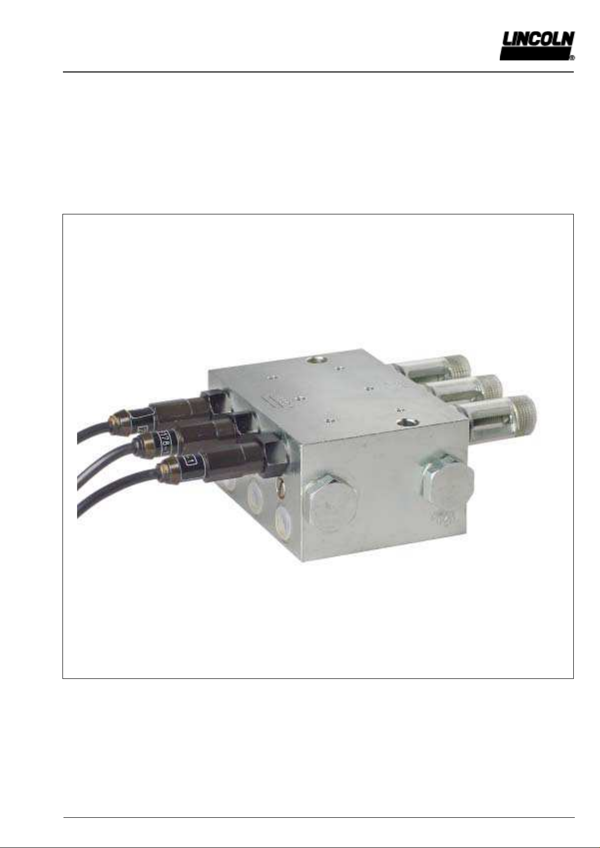
Two-line Lubricant Metering Devices
Model VSG-KR / VSL-KR
4289a00
Owner’s Manual
Operating Instructions and Spare Parts Lists
Page 2 of 14
1.2A-28001-C05
Subject to modifications
LINCOLN GmbH & Co. KG • Postfach 1263 • D-69183 Walldorf • Tel +49 (6227) 33-0 • Fax +49 (6227) 33-259
General Information
Appropriate Use
Use the two-line metering devices of the VSG/VSL series only
for the supply of lubricant in centralized lubrication systems.
Geeneral Safety Instructions
Do not install or remove the metering devices when the
system is under pressure or the pump in operation.
•
Always protect the centralized lubrication system
connected to the pump with a pressure reducing valve.
•
Incorrect operation may lead to damage resulting from
insufficient or excessive lubrication of bearings or
lubrication points.
•
Your own alterations or modifications of an installed
sy stem should only be carried out if approved with the
manufacturer or his appointed dealer.
•
Use only original LINCOLN spare parts or parts
authorized by LINCOLN
Regulations for Prevention of Accidents
• Adhere to the rules valid in the country where the unit
will be in operation.
Installation
For all work at the metering device, observe extreme
cleanliness
– Attach the metering devices to even surfaces without
tension.
When base plates are used (see Accessories), first weld
the base plates without the metering devices and then
attach the metering devices onto them.
– Protect the metering devices from dust and influences of
heat (observe the maximum admissible operating
temperatures).
– The metering devices must be easily accessible for .
check and installation work.
· Before connecting the feed lines to the metering
devices, fill them with lubricant.
· When connecting the main lines take care to always
connect the same line (I or II) to the same metering
device inlet.
This makes it easier to check of the metering device
because all indicator pins are either in or out after each
cycle.
Table of Contents
Page
General information ................................................................ 2
Technical data ........................................................................ 3
Model identification ................................................................. 5
Description of operation .......................................................... 6
Installation ............................................................................ 10
Accessories ........................................................................... 11
Spare parts ........................................................................... 12
Operation, Maintenance and Repair
Repairs should be carried out only by qualified persons who
have been charged with the repair work and are familiar with
centralized lubrication systems.
Since the pistons in the metering devices are fit with the
smallest tolerances, the metering device must be replaced
when the pistons are worn.
When synthetic lubricants are used, bear in mind that they
must be compatible with the sealing material of the metering
devices (polyurethane or FKM).
Use only lubricants which are appropriate for centralized
lubrication systems. If in doubt, ask the supplier.
Further Information:
For the VSG-MR version:
Adjusting device with magnetically operated indication of
function (1.2A-18002-A96)
For the VSG-KR-NP version:
Data sheet „Piston detector“ (9.3A-20016-A00)
Subject to modifications
Owner’s Manual
Operating Instructions and Spare Parts Lists
Page 3 of 14
1.2A-28001-C05
LINCOLN GmbH & Co. KG • Postfach 1263 • D-69183 Walldorf • Tel +49 (6227) 33-0 • Fax +49 (6227) 33-259
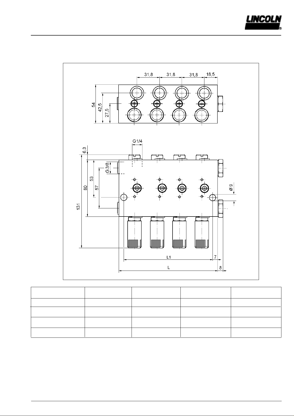
Technical Data:
Output volume: Q = 0-2,2 cm3/stroke, adjustable
Operating pressure: p
max
= 400 bar,
p
min
= 35 bar
Main line connection: G3/
8
Feed line connection: G1/
4
T echnical Dat a VSG-KR
TYPE VSG2-KR VSG4-KR VSG6-KR VSG8-KR
Number of outlets 2 4 6 8
L1 (mm) 30,5 62 94 126
L (mm) 44,5 76 108 140
Part no. 620-40015-1 620-40015-3 620-40015-5 620-40015-7
4290a00
Owner’s Manual
Operating Instructions and Spare Parts Lists
Page 4 of 14
1.2A-28001-C05
Subject to modifications
LINCOLN GmbH & Co. KG • Postfach 1263 • D-69183 Walldorf • Tel +49 (6227) 33-0 • Fax +49 (6227) 33-259
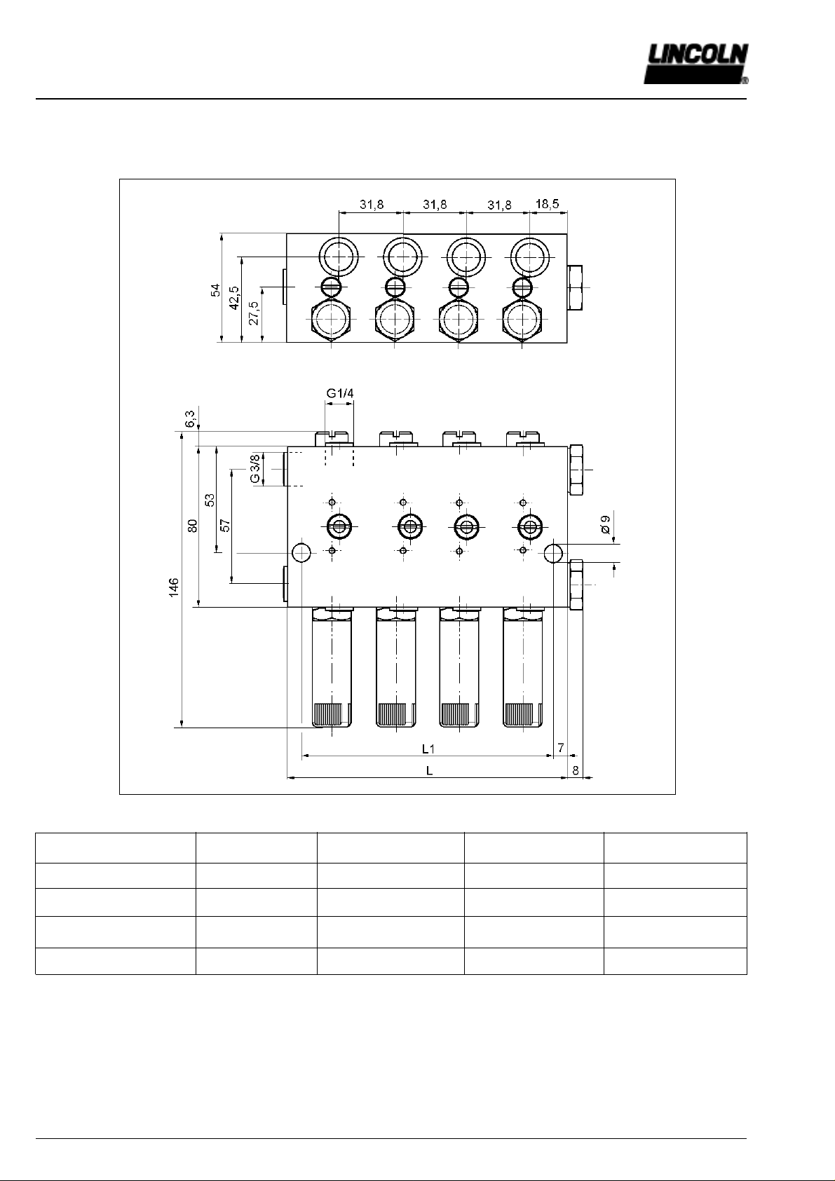
T echnical Dat a VSL-KR
Technical Data:
Output volume: Q = 0-5 cm3/stroke, adjustable
Operating pressure: p
max
= 400 bar,
p
min
= 35 bar
Maine line connection: G3/
8
Feed line connection: G1/
4
TYPE VSL2-KR VSL4-KR VSL6-KR VSL8-KR
Number of outlets 2 4 6 8
L1 (mm) 30,5 62 94 126
L (mm) 44,5 76 108 140
Part no. 620-40062-3 620-40062-7 620-40064-3 620-40064-7
4291a00
Subject to modifications
Owner’s Manual
Operating Instructions and Spare Parts Lists
Page 5 of 14
1.2A-28001-C05
LINCOLN GmbH & Co. KG • Postfach 1263 • D-69183 Walldorf • Tel +49 (6227) 33-0 • Fax +49 (6227) 33-259
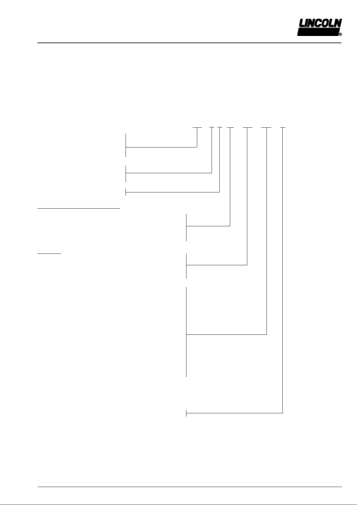
VSG/VSL Idendification Chart
Examples of type designations:
VSG 2 - D 1,1
VSL 8 - KR FKM protection cap MS
VSG 6 KR - NP
VSG VA3 - KR VA
VS G 4 - KR - KNTU - A
VSG 1 - MR
VSL 8 - KR - KSC
Basic type
G : Max. output volume 2,2 cm³
L : Max. output volume 5 cm³
Standard version
Steel body, galvanized
VA : stainless body 1.4305
Number of outlets 1 to 8
Adjusting of output and monitoring
KR : with indicator pin and progressive adjustment
KD : with indicator pin and metering screws
D : with metering screws (output volume in cm³)
MR: adjustment with magnetically operated indication
Adjusting:
Standard version: steel, galvanized
VA : stainless steel 1.4305
FKM : adjustment with FKM seal (over 80°C)
(standard: polyurethane)
KN : with indicator pin and progressive adjustment
as well as fitted proximity switch per pair
of outlets
KA : with indicator pin and adapter
(proximity switch to be supplied by customer)
KS : with indicator pin and progressive adjustment
as well as fitted limit switch per pair of outlets
NP : with integrated proximity switch
(piston detector)
Protection cap MS: Protection cap brass
C,TU : internal abbreviations
A : USA-version (NPT thread)
Note: The metering devices model D and KD are supplied
with metering screws for maximum output (2.2 or 5 cm3)
when no other specification is indicated.
 Loading...