

Page 1

VRTEX™360
IM10046-A
July, 2010
For use with machines having Code Numbers:
Safety Depends on You
Lincoln equipment is designed
an d bu ilt with sa fety in min d.
However, your overall safety can
be increased by proper installation ... and thoughtful operation
on your part. DO NOT INSTALL,
OPERATE OR REPAIR THIS
EQUIPMENT WITHOUT READING THIS MANUAL AND THE
SAFETY PRECAUTIONS CONTAINED THROUGHOUT. And,
most importantly, t hink before
you act and be careful.
AD1332-1 Software Version 1.0.7.7
AD1332-2
NOTICE
The VRTEX
tual reality arc welding
training machine only
and NOT a real arc
welder. When welding
with arc welding equipment, be aware of all
standard safety practices
associated with arc welding. Some standard
warnings are included in
this manual.
TM
360 is a vir-
OPERATOR’S MANUAL
• Sales and Service through Subsidiaries and Distributors Worldwide •
Cleveland, Ohio 44117-1199 U.S.A. TEL: 888.935.3878 FAX: 216.383.8823 WEB SITE: www.VRTEX360.com
Copyright © Lincoln Global Inc.
• World's Leader in Welding and Cutting Products •
Page 2

Page 3
i
SAFETY
i
WARNING
CALIFORNIA PROPOSITION 65 WARNINGS
Diesel engine exhaust and some of its constituents
are known to the State of California to cause cancer, birth defects, and other reproductive harm.
The Above For Diesel Engines
ARC WELDING CAN BE HAZARDOUS. PROTECT YOURSELF AND OTHERS FROM POSSIBLE SERIOUS INJURY OR DEATH.
KEEP CHILDREN AWAY. PACEMAKER WEARERS SHOULD CONSULT WITH THEIR DOCTOR BEFORE OPERATING.
Read and understand the following safety highlights. For additional safety information, it is strongly recommended that you
purchase a copy of “Safety in Welding & Cutting - ANSI Standard Z49.1” from the American Welding Society, P.O. Box
351040, Miami, Florida 33135 or CSA Standard W117.2-1974. A Free copy of “Arc Welding Safety” booklet E205 is available
from the Lincoln Electric Company, 22801 St. Clair Avenue, Cleveland, Ohio 44117-1199.
BE SURE THAT ALL INSTALLATION, OPERATION, MAINTENANCE AND REPAIR PROCEDURES ARE
PERFORMED ONLY BY QUALIFIED INDIVIDUALS.
The engine exhaust from this product contains
chemicals known to the State of California to cause
cancer, birth defects, or other reproductive harm.
The Above For Gasoline Engines
FOR ENGINE
powered equipment.
1.a. Turn the engine off before troubleshooting and maintenance
work unless the maintenance work requires it to be running.
____________________________________________________
1.b. Operate engines in open, well-ventilated
areas or vent the engine exhaust fumes
outdoors.
____________________________________________________
1.c. Do not ad d the fuel near an open flame
welding arc or when the engine is running.
Stop the engine and allow it to cool before
refueling to prevent spilled fuel from vaporizing on con tac t with hot engine parts and
igniting. Do not spill fuel when filling tank. If
fuel is spilled, wipe it up and do not start
engine until fumes have been eliminated.
____________________________________________________
1.d. Keep all equipment safety guards, covers and devices in
position and in good repair.Keep hands, hair, clothing and
tools away from V-belts, gears, fans and all other moving
parts when starting, operating or repairing equipment.
____________________________________________________
1.e. In so me ca se s it may be ne ce ss ar y to remove safety
gu a rds to p erf o rm r equ ire d ma i nt e nan ce. Rem ove
guards only when necessary and replace them when the
ma i nte nan ce re q uir ing th ei r remo val is co mpl ete .
Always use the greatest care when working near moving
parts.
___________________________________________________
1.f. Do not put your hands near the engine fan.
Do not attempt to override the governor or
idler by pushing on the throttle control rods
while the engine is running.
1.h. To avoid scalding, do not remove the
radiator pressure cap when the engine is
hot.
ELECTRIC AND
MAGNETIC FIELDS
may be dangerous
2.a. Electric current flo wing thr ough any conductor caus es
localized Electri c and Mag netic Field s (EMF). Welding
current cre ates EMF fields aro und welding ca bles and
welding machines
2.b. EMF fields may interfere wi th so me pa ce makers, and
welders having a pacemaker should consult their physician
before welding.
2.c. Exposure to EMF fields in welding may have other health
effects which are now not known.
2.d. All welders should use the following procedures in order to
minimize exposure to EMF fields from the welding circuit:
2.d.1.
Route the electrode and work cables together - Secure
them with tape when possible.
2.d.2. Nev er co il th e electr ode l ead around your body .
2.d.3. Do not place your body between the electrode and
work cables. If the electrode cable is on your right
side, the work cable should also be on your right side.
___________________________________________________
1.g. To prevent accidentally starting gasoline engines while
turning the engine or welding generator during maintenance
work, disconnect the spark plug wires, distributor cap or
magneto wire as appropriate.
2.d.4. Connect the work cable to the workpiece as close as
possible to the area being welded.
2.d.5. Do not work next to welding power source.
VRTEXTM360
Page 4
ii
SAFETY
ii
ELECTRIC SHOCK can
kill.
3.a. The electrode and work (or ground) circuits
are electrically “hot” when the welder is on.
Do not touch these “hot” parts with your bare
skin or wet clothing. We ar dry, hole-free
gloves to insulate hands.
3.b. Insulate yourself from work and ground using dry insulation.
Make certain the insulation is large enough to cover your full
area of physical contact with work and ground.
In addition to the normal safety precautions, if welding
mu st be perform ed under electrically hazardous
conditions (in damp locations or while wearing wet
clothing; on metal structures such as floors, gratings or
scaffolds; when in cramped positions such as sitting,
kneeling or lying, if there is a high risk of unavoidable or
accidental contact with the workpiece or ground) use
the following equipment:
• Semiautomatic DC Constant Voltage (Wire) Welder.
• DC Manual (Stick) Welder.
• AC Welder with Reduced Voltage Control.
3.c. In semiautomatic or automatic wire welding, the electrode,
electrode reel , welding head , nozzle or semiautomatic
welding gun are also electrically “hot”.
3.d. Always be sure the work cable makes a good electrical
connection with the metal being welded. The connection
should be as close as possible to the area being welded.
3.e. Ground the work or metal to be welded to a good electrical
(earth) ground.
3.f.
Maintain the electrode holder, work clamp, welding cable and
welding machine in good, safe operating condition. Replace
damaged insulation.
3.g. Never dip the electrode in water for cooling.
3.h. Never simultaneously t ou ch el ec tr ic al ly “hot” pa rt s of
electrode holders connected to two welders because voltage
between the two can be the total of the open circuit voltage
of both welders.
3.i. When working above floor level, use a safety belt to protect
yourself from a fall should you get a shock.
3.j. Also see Items 6.c. and 8.
ARC RAYS can burn.
4.a. Use a shield with the proper filter and cover
plates to protect your eyes from sparks and
the rays of the arc when welding or observing
open arc welding. Headshield and filter lens
should conform to ANSI Z87. I standards.
4.b. Use suitable clothing made from durable flame-resistant
material to protect your skin and that of your helpers from
the arc rays.
4.c. Protect other nearby personnel with suitable, non-flammable
screening and/or warn them not to watch the arc nor expose
themselves to the arc rays or to hot spatter or metal.
FUMES AND GASES
can be dangerous.
5.a. Weldi ng may produce fumes and gases
hazardous to health. Avoid breathing these
fumes and gases. Wh en welding , k eep
your head out of the fume. Use enough
ventilation and/or exhaust at the arc to keep
fumes and gases away from the breathing zone. When
we lding with ele ctr odes wh ich req uir e sp eci al
ve nti lat ion such as sta inl ess or hard fac ing (see
instructions on container or MSDS) or on lead or
cadmium plated steel and other metals or coatings
which produce highly toxic fumes, keep exposure as
low as possible and within applicable OSHA PEL and
ACGIH TLV limits using local exhaust or mechanical
ventilation. In confined spaces or in some circumst anc es, outdoors, a res pir ato r ma y be r equ ire d.
Additional precautions are also required when welding
on galvanized steel.
5. b. The operation of welding fume control equipment is affected
by various factors including proper use and positioning of
the equipment, maintenance of the equipment and the specific welding procedure and application involved. Worker
exposure level should be checked upon installation and
periodically thereafter to be certain it is within applicable
OSHA PEL and ACGIH TLV limits.
5.c.
Do not weld in locations near chlorinated hydrocarbon
coming from degreasing, cleaning or spraying operations.
The heat and rays of the arc can react with solvent vapors
form phosgene, a highly toxic gas, and other irritating products.
5.d. Shielding gases used for arc welding can displace air and
cause injury or deat h. Al wa ys use e nough ventil at ion,
especially in confined areas, to insure breathing air is safe.
vapors
to
5.e. Read and understand the manufacturer’s instructions for this
equipment and the consumables to be used, including the
ma t eri al safe ty da ta shee t ( MSD S) and fo llo w you r
employer’s safety practices. MSDS forms are available from
yo u r weld ing di str i but or or fro m th e manu fac tur er.
5.f. Also see item 1.b.
VRTEXTM360
Page 5
iii
SAFETY
iii
WELDING and CUTTING
SPARKS can
cause fire or explosion.
6.a.
Remove fire hazards from the welding area.
If this is not possible, cover them to prevent
Re m emb er t hat wel din g sp ark s an d hot
materials from welding can easily go through small cracks
an d open ings t o adj acent areas . Avo id w el ding n ear
hydraulic lines. Have a fire extinguisher readily available.
6.b. Where compressed gases are to be used at the job site,
special precautions should be used to prevent hazardous
situations. Refer to “Safety in Welding and Cutting” (ANSI
Stand ard Z49.1) and the operating information for the
equipment being used.
6.c. When not welding, make certain no part of the electrode
circuit is touching the work or ground. Accidental contact
can cause overheating and create a fire hazard.
6.d. Do not heat, cut or weld tanks, drums or containers until the
proper steps have been taken to insure that such procedures
will not cause flammable or toxic vapors from substances
inside. They can cause an explosion even
been “cleaned”. For information, purchase “Recommended
Safe Practices for the
Co n tai ner s and Pip ing Th at Hav e Held Ha zar dou s
Substances”, AWS F4.1 from the American Welding Society
(see address above).
6.e. Vent hollow castings or containers before heating, cutting or
welding. They may explode.
Sparks and spatter are thrown from the welding arc. Wear oil
6.f.
free protective garments such as leather gloves, heavy shirt,
cuffless trousers, high shoes and a cap over your hair. Wear
ear plugs when welding out of position or in confined places.
Always wear safety glasses with side shields when in a
welding area.
6.g. Connect the work cable to the work as close to the welding
area as practical. Work cables connected to the building
framework or other locations away from the welding area
increase th e possibili ty of the welding current pas sing
through lifting chains, crane cables or other alternate circuits. This can create fire hazards or overheat lifting chains
or cables until they fail.
6.h. Also see item 1.c.
the welding sparks from st arting a fire.
though
they have
Preparation
for Welding and Cutting of
CYLINDER may explode
if damaged.
7.a. Us e onl y com pre sse d gas c yli nde r s
containing the correct shielding gas for the
pr o ces s us ed a n d pr ope rly o per ati ng
re g ula tor s d esi gne d f or th e g as an d
pressure used. All hoses, fittings, etc. should be suitable for
the application and maintained in good condition.
7.b. Always keep cylinders in an upright position securely
chained to an undercarriage or fixed support.
7.c. Cylinders should be located:
• Away from areas where they may be struck or subjected to
physical damage.
• A safe distance from arc welding or cutting operations and
any other source of heat, sparks, or flame.
7.d. Never allow the electrode, electrode holder or any other
electrically “hot” parts to touch a cylinder.
7.e. Keep your head and face away from the cylinder valve outlet
when opening the cylinder valve.
7.f. Valve protection caps should always be in place and hand
tight except when the cylinder is in use or connected for
use.
7.g. Re ad and fo ll ow the in struction s on c om pressed ga s
cylinders, associated equipment, and CGA publication P-l,
“Precautions for Safe Handling of Compressed Gases in
Cylinders,” available from the Compressed Gas Association
1235 Jefferson Davis Highway, Arlington, VA 22202.
FOR ELECTRICALLY
powered equipment.
8.a. Turn off input power using the disconnect
switch at the fuse box before working on
the equipment.
8.b. Ins tall equipment in ac cordance with the U.S. National
Electrical Co de, all local codes and the manufacturer’s
recommendations.
8.c. Ground the equipment in accordance with the U.S. National
Electrical Code and the manufacturer’s recommendations.
6.I. Read and follow NFPA 51B “ Standard for Fire Prevention
During Welding, Cutting and Other Hot Work”, available
from NFPA, 1 Batterymarch Park, PO box 9101, Quincy, Ma
022690-9101.
6.j. Do not use a welding power source for pipe thawing.
Refer to http://www.lincolnelectric.com/safety for additional safety information.
VRTEXTM360
Page 6

iv
SAFETY
iv
PRÉCAUTIONS DE SÛRETÉ
Pour votre propre protection lire et observer toutes les instructions
et les précautions de sûreté specifiques qui parraissent dans ce
manuel aussi bien que les précautions de sûreté générales suivantes:
Sûreté Pour Soudage A L’Arc
1. Protegez-vous contre la secousse électrique:
a. Les circuits à l’électrode et à la piéce sont sous tension
quand la machine à souder est en marche. Eviter toujours
tout contact entre les parties sous tension et la peau nue
ou les vétements mouillés. Porter des gants secs et sans
trous pour isoler les mains.
b. Faire trés attention de bien s’isoler de la masse quand on
soude dans des endroits humides, ou sur un plancher
metallique ou des grilles metalliques, principalement dans
les positions assis ou couché pour lesquelles une grande
partie du corps peut être en contact avec la masse.
c. Maintenir le porte-électrode, la pince de masse, le câble
de soudage et la machine à souder en bon et sûr état
defonctionnement.
d.Ne jamais plonger le porte-électrode dans l’eau pour le
refroidir.
e. Ne jamais toucher simultanément les parties sous tension
des porte-électrodes connectés à deux machines à souder
parce que la tension entre les deux pinces peut être le
total de la tension à vide des deux machines.
f. Si on utilise la machine à souder comme une source de
courant pour soudage semi-automatique, ces precautions
pour le porte-électrode s’applicuent aussi au pistolet de
soudage.
2. Dans le cas de travail au dessus du niveau du sol, se protéger
contre les chutes dans le cas ou on recoit un choc. Ne jamais
enrouler le câble-électrode autour de n’importe quelle partie
du corps.
5. Toujours porter des lunettes de sécurité dans la zone de
soudage. Utiliser des lunettes avec écrans lateraux dans les
zones où l’on pique le laitier.
6. Eloigner les matériaux inflammables ou les recouvrir afin de
prévenir tout risque d’incendie dû aux étincelles.
7. Quand on ne soude pas, poser la pince à une endroit isolé de
la mas se. Un court-circ uit ac cidental peut pro voquer un
échauffement et un risque d’incendie.
8. S’assurer que la masse est connectée le plus prés possible
de la zone de travail qu’il est pratique de le faire. Si on place
la masse sur la charpente de la construction ou d’autres
endroits éloignés de la zone de travail, on augmente le risque
de voir passer le courant de soudage par les chaines de levage, câbles de grue, ou autres circuits. Cela peut provoquer
des risques d’incendie ou d’echauffement des chaines et des
câbles jusqu’à ce qu’ils se rompent.
9. Assurer une ventilation suffisante dans la zone de soudage.
Ceci est particuliérement important pour le soudage de tôles
galvanisées plombées, ou cadmiées ou tout autre métal qui
produit des fumeés toxiques.
10. Ne pas souder en présence de vapeurs de chlore provenant
d’o pérations de dégraissage, nettoyage ou pistolage. La
chaleur ou les rayons de l’arc peuvent réagir avec les vapeurs
du solvant pour produire du phosgéne (gas fortement toxique)
ou autres produits irritants.
11. Pour obtenir de plus amples renseignements sur la sûreté,
voir le code “Code for safety in welding and cutting” CSA
Standard W 117.2-1974.
PRÉCAUTIONS DE SÛRETÉ POUR
3. Un coup d’arc peut être plus sévère qu’un coup de soliel,
donc:
a. Utiliser un bon masque avec un verre filtrant approprié
ainsi qu’un verre blanc afin de se protéger les yeux du rayonnement de l’arc et des projections quand on soude ou
quand on regarde l’arc.
b. Porter des vêtements convenables afin de protéger la
peau de soudeur et des aides contre le rayonnement de
l‘arc.
c. Protége r l ’autre person nel travaillant à proximité au
soudage à l’aide d’écrans appropriés et non-inflammables.
4. Des gouttes de laitier en fu sion sont émise s de l’arc de
soudage. Se protéger avec des vêtements de protection libres
de l’huile, tels que les gants en cuir, chemise épaisse, pantalons sans revers, et chaussures montantes.
LES MACHINES À SOUDER À
TRANSFORMATEUR ET À
REDRESSEUR
1. Relier à la terre le chassis du poste conformement au code de
l’électricité et aux recommendations du fabricant. Le dispositif
de montage ou la piece à souder doit être branché à une
bonne mise à la terre.
2. Autant que possible, I’installation et l’entretien du poste seront
effectués par un électricien qualifié.
3. Avant de faires des travaux à l’interieur de poste, la debrancher à l’interrupteur à la boite de fusibles.
4. Garder tous les couvercles et dispositifs de sûreté à leur
place.
VRTEXTM360
Page 7

v
SAFETY
v
WARNINGS
Do not place objects on the VR Table, Arm
or Weld Machine.
Handle the Face Mounted Display (FMD)
integrated helmet with care. When not in
use, the Helmet should be placed on the
helmet hanger peg. If you will not be
using the system for longer than 4 hours,
shut down your VRTEX(TM) 360 System.
Handle t h e VR SMAW device and V R
GMAW/FCAW gun with care. When not in
use, these items should be placed on the
appropriate holders located on the sides
of the VR machine. These devices are
customized and cannot be used on normal welding machines.
Handle the VR Coupons with care. When
not in use, store them in the Coupon
Drawer at the b a c k o f the VR Weld
Machine.
During lightning storms, turn off the system and unplug it from the power outlet.
VRTEXTM360
Page 8
vi
SAFETY
vi
Recycling Welding Equipment at End of Life
Waste Electrical and Electronic Equipment (WEEE)
Recycling
Recycling and reclamation of used electrical and electronic equipment is important to many nations and localities. Lincoln
Electric provides information to assist in the recycling of welding equipment.
This parts list contains a “WEEE” column. The WEEE column describes potential recyclable materials. Materials that
require selective treatment, according to national regulations, are also identified in the WEEE column.
The following table describes substances that are potentially recyclable. Components with high substance content are
identified within the parts list. Easily identified and common components such as steel screws, steel nuts, steel washers
and copper wire are not identified on the list, but are also recyclable. Some components may contain mixed substances.
Substance
Steel, Iron Fe
Aluminum
Copper
Recyclable Material
Identification
Al
Cu
WEEE in Europe
This instruction is mandatory for equipment in Europe that displays this symbol:
Do not dispose of electrical equipment together with normal waste!
In observance of European Directive 2002/96/EC on Waste Electrical and Electronic Equipment (WEEE) and its implementation in accordance with national law, electrical equipment that has reached the end of its life must be collected separately and returned to an environmentally compatible recycling facility. As the owner of the equipment, you should get
information on approved collection systems from your local Lincoln representative. By applying this European Directive
you will protect the environment and human health!
The following components must be removed from the welding equipment and shall be selectively treated. They shall be
disposed of or recovered in compliance with Council Directive 75/442/EEC. They are identified within the parts pages:
Component
Selective Treatment
Identification
Printed circuit boards with surface greater than 10 square centimeters ST
Liquid crystal displays with surface greater than 100 square centimeters ST
External electric cables (not all external cables are shown on parts pages) ST
Electrolyte capacitors with height >25 mm and diameter >25 mm or proportionately
similar in volume
ST
VRTEXTM360
Page 9
Thank You
viivii
for selecting a QUALITY product by Lincoln Electric. We want you
to take pride in operating this Lincoln Electric Company product
••• as much pride as we have in bringing this product to you!
The business of The Lincoln Electric Company is manufacturing and selling high quality welding equipment, consumables, and cutting equipment. Our challenge is to meet the needs of our customers and to exceed their expectations. On occasion, purchasers may ask Lincoln
Electric for advice or information about their use of our products. We respond to our customers based on the best information in our possession at that time. Lincoln Electric is not in a position to warrant or guarantee such advice, and assumes no liability, with respect to such information or advice. We expressly disclaim any warranty of any kind, including any warranty of fitness for any customer’s particular purpose,
with respect to such information or advice. As a matter of practical consideration, we also cannot assume any responsibility for updating or
correcting any such information or advice once it has been given, nor does the provision of information or advice create, expand or alter any
warranty with respect to the sale of our products.
Lincoln Electric is a responsive manufacturer, but the selection and use of specific products sold by Lincoln Electric is solely within the control
of, and remains the sole responsibility of the customer. Many variables beyond the control of Lincoln Electric affect the results obtained in
applying these types of fabrication methods and service requirements.
Subject to Change – This information is accurate to the best of our knowledge at the time of printing. Please refer to www.lincolnelectric.com
for any updated information.
CUSTOMER ASSISTANCE POLICY
Please Examine Carton and Equipment For Damage Immediately
When this equipment is shipped, title passes to the purchaser upon receipt by the carrier. Consequently, Claims
for material damaged in shipment must be made by the purchaser against the transportation company at the
time the shipment is received.
Please record your equipment identification information below for future reference. This information can be
found on your machine nameplate.
Product _________________________________________________________________________________
Model Number ___________________________________________________________________________
Code Number or Date Code_________________________________________________________________
Serial Number____________________________________________________________________________
Date Purchased___________________________________________________________________________
Where Purchased_________________________________________________________________________
Whenever you request replacement parts or information on this equipment, always supply the information you
have recorded above. The code number is especially important when identifying the correct replacement parts.
On-Line Product Registration
- Register your machine with Lincoln Electric either via fax or over the Internet.
• For faxing: Complete the form on the back of the warranty statement included in the literature packet
accompanying this machine and fax the form per the instructions printed on it.
• For On-Line Registration: Go to our
“Product Registration”. Please complete the form and submit your registration.
Read this Operators Manual Completely before attempting to use this equipment. Save this manual
and keep it handy for quick reference. Pay particular attention to the safety instructions we have provided for your protection. The level of seriousness to be applied to each is explained below:
WEB SITE at www.lincolnelectric.com. Choose “Quick Links” and then
WARNING
This statement appears where the information must be followed exactly to avoid serious personal injury or loss of life.
CAUTION
This statement appears where the information must be followed to avoid minor personal injury or damage to this equipment.
VRTEXTM360
Page 10

viii
TABLE OF CONTENTS
Page
Installation .......................................................................................................Section A
Graphic Symbols ..................................................................................................................A-1
Technical Specifications.......................................................................................................A-2
Safety ...................................................................................................................................A-3
Location................................................................................................................................A-3
Environmental Area..............................................................................................................A-3
Stacking/Tilting/Lifting ..........................................................................................................A-3
High Frequency Interference Protection...............................................................................A-3
General Description..............................................................................................................A-4
Design Features ...................................................................................................................A-4
Hardware Uncrating & Set-up........................................................................................A-4/A-7
________________________________________________________________________________
Operation .........................................................................................................Section B
Product Description ..............................................................................................................B-1
User Interface Overview.......................................................................................................B-2
Hardware Specifications ................................................................................................B-3/B-5
Powering Up.........................................................................................................................B-6
Login Screen ........................................................................................................................B-7
Joint Configuration ...............................................................................................................B-8
Process Selection.................................................................................................................B-9
Stand Set-up ........................................................................................................................B-9
VR Coupons .........................................................................................................................B-9
Table/Arm Rotation ............................................................................................................B-10
Environment .......................................................................................................................B-11
VR Gas Set-up ...................................................................................................................B-11
Weld Machine Settings.......................................................................................................B-12
Push Buttons ......................................................................................................................B-13
Travel / Work Angle............................................................................................................B-14
Welders View .....................................................................................................................B-15
Instructors View..................................................................................................................B-15
LASER (Live Action Student Evaluation Report)................................................................B-15
Technique Parameters .......................................................................................................B-16
Position...............................................................................................................................B-17
Work/Travel Angle..............................................................................................................B-17
Pass Number, Travel Direction, Discontinuities .................................................................B-18
Instructor Mode ..................................................................................................................B-19
Updates ..............................................................................................................................B-19
Weldometer
Tolerance Editor .................................................................................................................B-21
Choosing Tolerance Set-up................................................................................................B-22
Choosing Tolerance To Load .............................................................................................B-22
Tolerances Screen(s) ................................................................................................B-22/B-25
Tolerances Whip & Travel Speed.......................................................................................B-26
Default Weld Processes Settings .......................................................................................B-27
________________________________________________________________________________
TM
.....................................................................................................................B-20
viii
Maintenance ....................................................................................................Section D
Cleaning & Maintenance .......................................................................................D-1
________________________________________________________________________
Troubleshooting..............................................................................................Section E
How to Use Troubleshooting Guide.......................................................................E-1
Troubleshooting Guide....................................................................................E-2/E-3
________________________________________________________________________
Wiring Diagrams..............................................................................................Section F
________________________________________________________________________
Parts Pages..............................................................................................................P638
VRTEXTM360
Page 11
A-1
INSTALLATION
GRAPHIC SYMBOLS THAT APPEAR ON
THIS MACHINE OR IN THIS MANUAL
A-1
1
INPUT POWER
ON
OFF
CIRCUIT BREAKER
INPUT POWER
SINGLE PHASE
ALTERNATING CURRENT
READ THIS OPERATORS
MANUAL COMPLETELY
U
1
I
1
INPUT VOLTAGE
INPUT CURRENT
PROTECTIVE
GROUND
WARNING or CAUTION
Documentation must be consulted in all cases where this
symbol is displayed.
Explosion
Dangerous Voltage
USB
Shock Hazard
Shock Hazard
VRTEXTM360
Page 12

A-2
INSTALLATION
TECHNICAL SPECIFICATIONS: AD1332-1 (STD. FREQ.) / AD1332-2 (ALT. FREQ.)
VRTEX™360 - VIRTUAL REALITY WELDING TRAINER
INPUT
MAKE/MODEL DESCRIPTION INPUT VOLTAGE INPUT CURRENT
+/- 10% (MAX.)
A-2
AD1332-1
AD1332-2
Standard Frequency 115-230 VAC (50-60 HZ) 4A-2A Single Phase
Alternate Frequency 115-230 VAC (50-60 HZ) 4A-2A Single Phase
WARNING
THIS PRODUCT INCORPORATES A PROTECTIVE EARTH IN THE AC POWER CORD. THE AC PLUG
SHOULD ONLY BE INSERTED INTO A SOCKET OUTLET PROVIDED WITH A
PROTECTIVE EARTH CONTACT.
TRACKING SYSTEM FREQUENCY
MAKE/MODEL DESCRIPTION OPERATING FREQUENCY
AD1332-1
AD1332-2
PHYSICAL DIMENSIONS (MACHINE W/MONITOR)
HEIGHT WIDTH DEPTH WEIGHT
71.0 in. 30.0 in. 50.0 in. 360 lbs.
1803 mm 762 mm 1270 mm 163 kg.
Standard Frequency HIGH
Alternate Frequency LOW
1
C
PHYSICAL DIMENSIONS (STAND)
HEIGHT WIDTH DEPTH WEIGHT
78.0 in. 39.0 in. 47.0 in. 102 lbs.
1981 mm 990 mm 1194 mm 46 kg.
TEMPERATURE RANGES
OPERATING TEMPERATURE RANGE STORAGE TEMPERATURE RANGE
0
- 950F5
41
0
- 350C 320 - 1490F 00 - 650C
RELATIVE HUMIDITY OPERATING ALTITUDES
80% For Temperatures Up To 880F / 310C
50% @ 1040F / 400C 6562 Feet (2000 Meters)
ENVIRONMENT
This Product is Pollution Degree 1.
THIS PRODUCT HAS BEEN TESTED TO THE REQUIREMENTS OF CAN/CSA-C22.2 NO. 61010-1,
2ND EDITION, INCLUDING AMENDMENT 1, OR A LATER VERSION OF THE SAME STANDARD
INCORPORATING THE SAME LEVEL OF TESTING REQUIREMENTS.
VRTEXTM360
Page 13
A-3
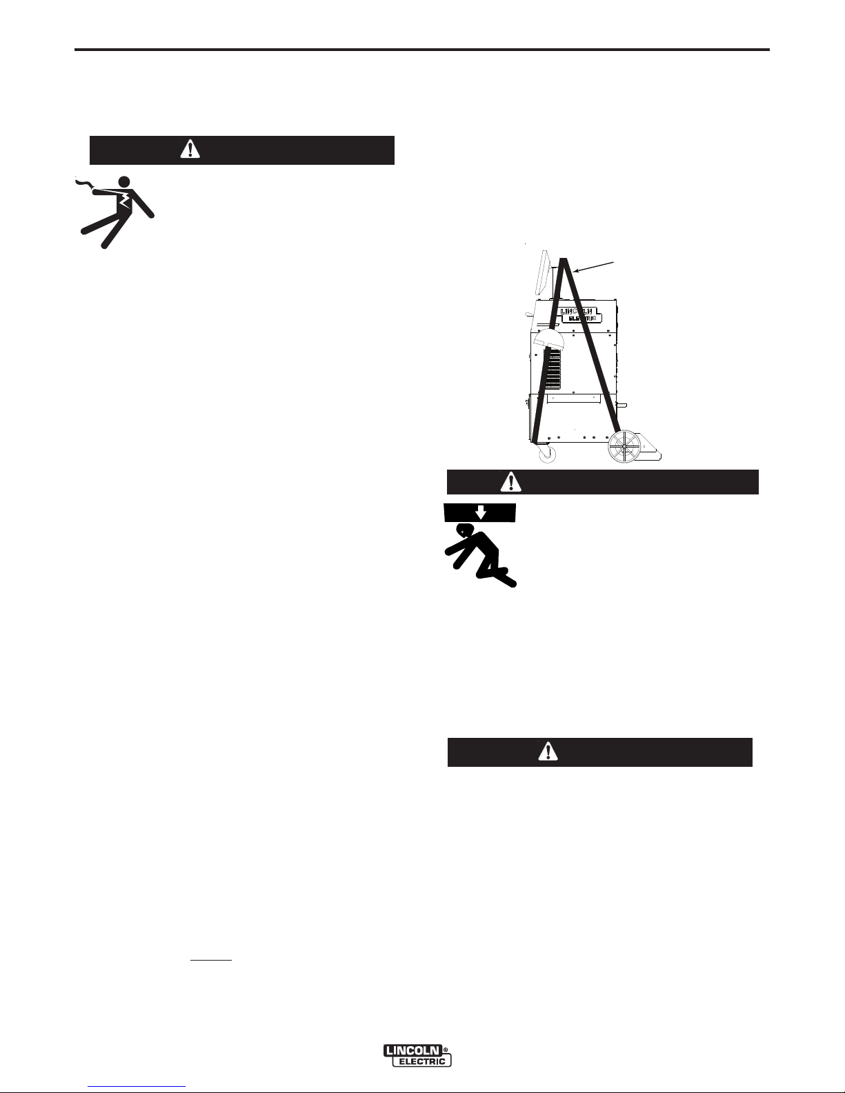
STRAPS
STRAPS
READ ENTIRE INSTALLATION SECTION BEFORE
STARTING INSTALLATION.
INSTALLATION
Safety Precautions
A-3
TILTING
Place the VRTEXTM360 directly on a secure, level surface.
WARNING
ELECTRIC SHOCK can kill.
• Only qualified personnel should perform this installation.
• Tur n the input p ower OFF and
unplug the machine from the receptacle before working on this equipment.
•
• Always connect the
ply grounded according to the National Electrical
Code and local codes.
------------------------------------------------------------
SELECT SUITABLE LOCATION
The machine will not operate in harsh environments.
It is important that simple preventative measures are
followed in order to assure long life and reliable operation. This product is for INDOOR USE ONLY.
• Dirt and dust that can be drawn into the machine
should be kept to a minimum. Failure to observe
these precautions can result in excessive operating
temperatures and nuisance shutdown.
• Do not locate where monitor is exposed to direct
sunlight.
VRTEXTM360
to a power sup-
If lifting the
rated for 500 pounds (226.8 kg) or more. Do not attempt to
lift the
VRTEXTM360
VRTEXTM360
is required, use two straps, each
with accessories attached to it.
• Lift only with equipment of adequate lifting capacity.
• Be sure machine is stable when
lifting.
• Do not operate machine while
suspended or when lifting.
• Do not place equipment near radiant heat sources.
• Do not place in a confined space. Allow a minimum
of 3 feet of clearance around machine and stand at
all times. Adequate ventilation is necessary.
• The circuit breaker switch on the rear panel is the
input power disconnect device. Do not position the
equipment so that it is difficult to operate the circuit
breaker.
• Route and protect power cable to minimize exposure
to damage.
ENVIRONMENTAL AREA
Keep the machine inside and dry at all times. Do not
place it on wet ground or in puddles. Never place liquids on top of the machine.
STACKING
The VRTEXTM360 cannot be stacked.
FALLING EQUIPMENT can cause injury.
------------------------------------------------------------------------
HIGH FREQUENCY INTERFERENCE PROTECTION
CAUTION
USE CAUTION WHEN OPERATING THIS MACHINE
AROUND OTHER EQUIPMENT.
• Large equipment, such as cranes, may interfere
with the operation of this machine.
• This machine may interfere with the operation of
other equipment in work/training area.
VRTEXTM360
Page 14

A-4
-1-2-1-2
-2-1-2-1
-1 -2 -1 -2
-2 -1 -2 -1
INSTALLATION
GENERAL DESCRIPTION
The VRTE XTM360 is a Virtual W elding Training
System and VRAW
Solution. This computer controlled interactive system
simulates arc welding through the use of realistic puddle graphics and sounds. This training system simulates multiple arc welding processes on a wide variety
of weld joint configurations. The VRTEX
sents the next generation of Virtual Reality (VR) welding training.
TM
(Virtual Reality Arc Welding)
TM
360 repre-
DESIGN FEATURES
HARDWARE OVERVIEW:
• Virtual Welding Machine, including:
o Monitor
o Coupon Drawer (back drawer)
o VR GMAW/FCAW Gun
o VR SMAW Device
o VR GMAW/FCAW Gun Holder
o VR SMAW Device Holder
o VR Helmet w/Face Mounted Display (FMD)
o Five VR Coupons - Flat Plate
Tee Joint
Groove Joint
2” Pipe XXS
6” Pipe Schedule 40
• Stand, including:
o Post
o Arm
o Table
o Pins
o Base
o Weights
A-4
HARDWARE UNCRATING:
TOOLS NEEDED
3/8” (9.5 mm) Wrench
3/16” (4.8 mm) Allen Wrench
Phillips Screwdriver
1. Decide on a location for your unit.
NOTE: The system requires approximately 8’ L x 8’
D x 8’ H (2.4 m L x 2.4 m D x 2.4 m H) of
space. Keep at least 3 feet in all directions
of both the stand and VR weld machine free
from obstruction. In addition, be conscious
of where you are placing the unit to avoid
magnetic fields, conductive, and high frequency ob jects and processes. H aving
these types of objects in the area can cause
interference and result in increased jitter
and/or distortion in the motion tracking.
TM
For best results, do not install VRTEX
machine in the welding lab. Electrical interference from power lines, though generally
small, can be present. Therefore all electrical power or lighting wiring within 50 feet of
the we lding area sha l l be e n closed in
grounded rigid metallic conduit. In the event
the VRTEX
TM
360 is affected by interference,
it is the user's responsibility to take steps to
isolate and/or eliminate the interference.
An uninterruptible power supply (UPS) may
be required for the protection of the system
from power irregularities or disruption.
MULTIPLE SYSTEM INSTALLATIONS
If multiple systems are required to operate together in
one location, a unique frequency transmitter can be
installed during the manufacturing process at Lincoln
Electric to reduce potential interference between systems. AD1332-1 systems have a standard frequency
source installed. AD1332-2 systems have an alternate
frequency source installed. For multiple system installations, alternate the -1 and -2 systems for best operation:
360
For Example: If 8 systems are to be installed in the VR
welding lab, the standard and alternate frequencies
should be positioned as seen below.
2. Using the 3/8” (9.5 mm) wrench, remove the screws
from the upper and lower front panels on the shipping crate.
NOTE: The rear of the crate is nailed on. Nail removal is
not required during the installation of this equipment.
VRTEXTM360
Page 15

A-5
INSTALLATION
FRONT
(upper)
FRONT
(lower)
BOLTS
3. Remove the six 3/8” (9.5 mm) bolts (three on each
side) from the bottom of the crate assembly.
A-5
6. Remove the monitor from the back of the machine.
7. Using the 3/8” (9.5 mm) wrench, remove the two
screws from the rear base securing the unit to the
wooden crate.
4. Car efull y s lide the cra te assem bly from the
VRTEXTM360 towards the rear of the machine. Be
careful to avoid damaging the welding device holders located on each side of the machine.
6. Carefu lly rem ove the po st (lo ng rectang ular
shaped cardboard box) from the crate.
5. Carefully cut and remove plastic wrapping from
the machine.
8. Remove the four screws from the wooden rear
cross brace.
9. Remove the wooden cross brace while ensuring
the unit is steady and secure.
10. Carefully roll the machine off the rear of the skid.
Ramping may be required.
11. Uncrate and unpack the table and table base.
VRTEXTM360
Page 16
A-6
Table
Weights
Stand
Screws
Table
Weights
Stand
Screws
INSTALLATION
5. Obtain the three post collar pins from the factory
packaging of the VRTEXTM360.
A-6
TABLE & SWING ARM SET-UP:
1. Place counter weights on base.
2. Using the 3/16” (4.8 mm) allen wrench, remove the
two ¼” x 20 Allen-head screws from the base
assembly.
NOTE: The longer screw is in the top.
Swing Arm
Table
Collar
Pins
6. Insert one of the collar pins into the post at the #6
location.
7. From the top, slide the table onto the post letting it
rest on the collar pin inserted in previous step.
8. Insert the second collar pin into the post at the #13
position.
9. Obtain the swing-arm from the rear of the VRTEX
360 by removing the cable ties from the swing arm
and cable. Grey cable should remain connected to
the VRTEX
TM
360 (DO NOT CUT!).
Post
T Pin
TM
3. Insert red post into base assembly aligning the flat
on the pole with the hole.
NOTE: The post will only insert one way.
4. Using the 3/16” (4.8 mm) allen wrench, secure the
post into position by replacing and tightening the
screws.
Cable Tie
Grey Cable
(DO NOT CUT)
VRTEXTM360
Page 17

A-7
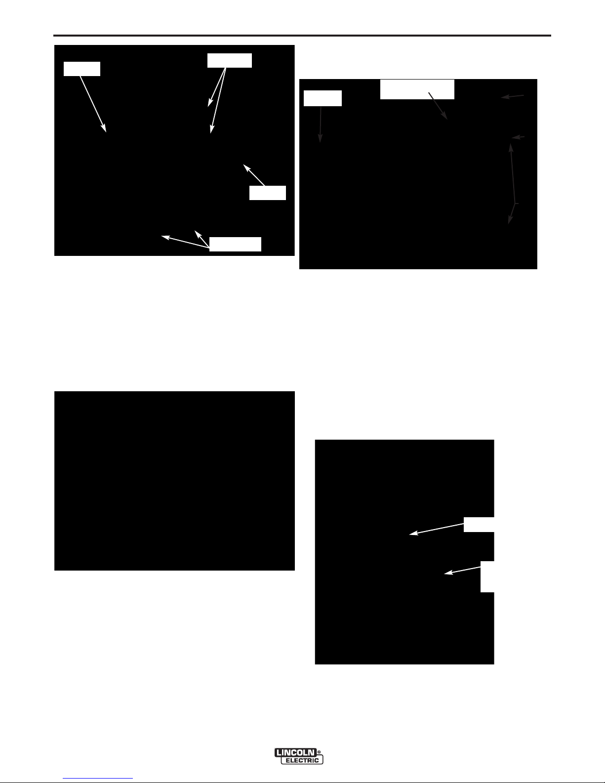
SVGA Out
Audio Jack
Always i
n
the On posi
tion
Input Power
connection
SVGA Out
Audio Jack
Always i
n
the On posi
tion
Input Power
connection
INSTALLATION
A-7
9. Carefully slide swing-arm onto post with the letters
(on the collar) “ABC” up and the grey cable located
on the bottom of the swing arm assembly.
10. Insert a third collar pin at a convenient height for
holding the helmet.
MONITOR:
Note: always use the factory supplied
monitor with the VRTEX(TM) 360
1. Remove monitor from cardboard box.
MONITOR (Mounting Screws)
Screws
BACK OF MACHINE
3. External speakers may be connected using the
audio jack located on the back of the machine.
TRACKING SYSTEM FUNDAMENTALS:
The magnetic tracking system is composed of the
following:
Input
VGA
Power
2. Remo v e the cable ties from monito r cabl e s
secured to the monitor mounting post.
3. Using a Phillips-head screwdriver to carefully
mount the monitor onto the mounting post bracket.
Tighten the four Phillips-head screws securely.
4. Connect input power cable and VGA cable into the
monitor.
APPLY SYSTEM POWER:
1. Insert the input supply power cord into the back
of the VRTEXTM360 and into a standard electrical
outlet capable of 115 to 230 VAC at 4 to 2 Amps.
ADDITIONAL FEATURES:
• Control Unit (Inside VR Machine)
o Contains the hardware and software neces-
sary to compute position and orientation.
• Source (part of the Swing Arm)
o The source contains electromagnetic coils
enclosed in a plastic shell that emit a magnetic
field. The source is the system’s reference
frame for sensor measurements.
• Sensor (in the VR GMAW/FCAW gun, VR SMAW
device, and helmet)
o The sensor contains electromagnetic coils
enclosed in a plastic shell that detect the magnetic fields emitted by the source. The sensor’s position and orientation are precisely
measured as it moves in reference to the
source. The sensor is completely passive,
having no active voltage applied to it.
1. The welding coupons are stored in the coupon
drawer in the rear of the machine.
2. The weld simulation can be displayed on an external monitor or projector by using the SVGA output
on the back of the machine. The external display
must support 1024x780 resolution.
VRTEXTM360
Page 18

B-1
1
2
3
6
7
8
10
11
9
6
5
4
12
14
13
1
2
3
6
7
8
10
11
9
6
5
4
12
14
13
PRODUCT DESCRIPTION
OPERATION
B-1
The VRTEXTM360 is a virtual reality arc welding training machin e only and NOT a real arc w elding
machine. Please be aware of all standard safety
practices associated with welding. Some standard
warnings are included in this manual.
If the equipment is used in a manner not specified by
the manufacturer, the protection provided to the
equipment and user may be impaired.
FRONT OF MACHINE
Access panels are not to be removed except by qualified service personnel due to risk of electric shock
from accessible live parts.
VRTEXTM360
Page 19

B-2
OPERATION
B-2
USER INTERFACE OVERVIEW
The VRTEXTM360 is a virtual reality arc welding trainer. This computer based training system is an educational tool designed to allow students to practice their
welding technique in a simulated environment. It promotes the efficient transfer of welding skills from the
classroom to the welding booth, while reducing material waste and energy consumption associated with traditional welding training.
See figure on page B-1 for locations of operator controls and indicators.
1. The monitor allows the student to view the setup
screens and provides an active view of the actual
welding process for teachers and students. The
monitor can be rotated for ease of viewing. Make
certain the power button on the monitor is ON and
the green LED is lit.
2. Th e joys tic k allo ws the op erator to nav igate
through various options by moving the red highlighted box and zoom / r o tate the coupon in the
Instructor View.
3. The colored buttons on the front of the machine
correlate to the colored rectangles at the bottom of
the monitor screen when the simulation software is
running. These buttons perform various functions
depending upon the command shown in the corresponding box on the screen.
10. The key switch is located on the lower right of the
control panel. When the system is in the login
screen the instructor may insert the key shipped
with the system into the key lock and then rotate it
90 degrees to the right. This allows the instructor
to access the instructor mode which includes the
Weldometer
Update screens.
11 Pressing and holding the green circular button
for 3 seconds powers up the VRTEX
Note: The green power button does not power
down the system. Select Log Out and Shutdown
from the red menu to turn off the system
12. The red select button accepts (enters) the data
displayed or highlighted on the monitor.
13. VR GMAW/FCAW gun holder should be used to
store the VR GMAW/FCAW gun when not in use.
14. VR SMAW devi ce hold er sho uld be used t o
store the VR SMAW device when not in use.
TM
, Tolerance Editor, Options and
TM
360 system.
4. The wire feed speed/amperage dial allows the
user to input wire feed speed or amperage depending on the VR welding process selected.
5. The voltage dial allows the user to input the weld-
ing voltage. This dial also allows input of trim values when pulse process is in use.
6. The left and right white screen select arrows
allow the operator to cycle through various screens.
7. The process selector switch is used to selected
the virtual welding process. (GMAW, FCAW, or
SMAW)
8. The polarity selector switch is used to indicate
the welding polarity for any given process. (DC+,
DC-, or AC).
9. The USB port is used to upload software and
download user data from the system.
VRTEXTM360
Page 20

B-3
OPERATION
B-3
HARDWARE SPECIFICS:
VR GMAW/FCAW GUN
The VR gun has a trigger that is used during the simulation of GMAW and FCAW processes to initiate and
main t ain the simul a ted weldin g a r c. T he V R
GMAW/FCAW gun should be placed on the round gun
holder on the right side when not in use.
VR GMAW/FCAW GUN
CAUTION
In order to strike an arc with the VR SMAW device,
strike or tap the tip of the rod (of the VR SMAW
device) on the coupon being welded. To break the
arc, move the VR SMAW device rod away from the
work piece.
CAUTION
Do not try to strike the arc with excessive force,
as the arc start is distance based. Excessive
force may result in da mage to the VR SM AW
device.
The angle of the rod can be changed by squeezing
the handle of the VR SMAW device. This allows the
rod to be moved into the 45 or 90 degree position.
Once the rod is at one of these angles, release the
handle. The rod should now be fixed in that position.
Do not change the rod angle while the rod is
extending or retracting.
VR SMAW DEVICE
Store gun as shown below to
avoid damage.
VR GMAW/FCAW GUN (Properly Stored)
VR SMAW DEVICE
The VR SMAW device has a rod that represents a
stick electrode. This rod retracts when a virtual arc is
struck to simulate the electrode burning off during the
virtual welding process. When the virtual electrode
burns down to a stub, the rod will stop retracting and
the user will no longer be able to weld. When the user
presses “new stick” in the orange actions menu button, the rod extends out, simulating that a new electrode was put into the VR SMAW device. When not in
use, the VR SMAW device should be placed in the VR
SMAW holder on the left side of the VR weld machine.
CAUTION
Store device as shown below to
avoid damage.
VR SMAW DEVICE (Properly Stored)
VRTEXTM360
Page 21

B-4
RATCHET KNOB
HEAD GEAR
FORE / AFT ADJUSTMENT
TILT ADJUSTMENT
CROWN
A
DJUSTMENT
PIN HOLES FOR
ADJUSTMENT
RATCHET KNOB
HEAD GEAR
FORE / AFT ADJUSTMENT
TILT ADJUSTMENT
CROWN
A
DJUSTMENT
PIN HOLES FOR
ADJUSTMENT
OPERATION
B-4
Helmet
Adjust the helmet so it fits comfortably. Adjustments
can be made by depressing and turning the knob at
the b ack of th e helm et unt il the de sired size i s
achieved. If necessary, the user may also have to
adjust the top crown adjustment to fit their head size.
HELMET FUNCTIONS
The helmet has an FMD (Face Mounted Display) on
the inside. These FMD lenses display the virtual environment to the user. Each lens can be shifted left or
right to align with the users eyes by applying gentle
pressure. In addition, the lenses can be lifted up and
down as well as shifted forward and back for the best
fit. The user should make sure the lenses are parallel
to their eyes. Keep the lenses clean at all times. See
Cleaning and Maintenance Section.
HELMET LENSES
Coupon Drawer
The coupon drawer houses the physical coupons.
When not in use, the coupons should be stored in the
drawer. To open the drawer, press the top indent
down, and slide the drawer out. Each coupon fits in
its own area defined by the foam locator in the drawer.
COUPON DRAWER
Coupons
The coupons represent the various workpieces on
which the user can virtually weld. During the virtual
welding process, they provide physical feedback to
the student.
There are five VR Coupons:
1. Flat Plate
2. Tee Joint
3. 3/8” Groove Joint w/Backing Bar
4. 2” Diameter XXS Pipe
5. 6” Diameter Schedule 40 Pipe
LENSES
When not in use, the helmet should be hung from the
stand or placed in the right front drawer to avoid being
damaged.
EAR
BUDS
VRTEXTM360
VR COUPONS
5
2
4
1
The coupons along with the VR SMAW device and VR
GMAW/FCAW gun have been factory calibrated at
Lincoln Electric.
3
Page 22

B-5
OPERATION
B-5
Stand
The stand is comprised of the post, arm, table, collar
pins, base and two weights. Users should position
themselves at the stand during virtual welding.
Post
The arm and table slide up and down and rest on the
collar pins that are inserted into the post. Hole numbers 0 through 28 indicate position of welding for program accuracy. The position that the table or arm is
located is read by identifying the numbered hole that
the pin has been inserted into.
POST W/PIN INSERTED IN #18
SWING ARM ROTATION
POS. A
POS. B
POS. C
Table
The table can be used to gain stability and learn proper body positioning. The base supports the stand and
has weights on the back to maintain stability. The
table can be swung out of the way when not in use.
CAUTION
Do n ot us e the Stand/Table w ithou t the base
counter weights properly positioned.
___________________________________________
Coupon Positioning In Swing Arm
The coupons can be inserted into the arm to accommodate flat, horizontal, vertical or overhead welding
positions. The knob on the front of the swing arm can
be pulled out for coupons to be inserted or removed
and pushed in for coupons to be secured. The front of
the swing arm can be rotated down at a 45 or 90degree angle to allow 2G, 5G and 6G pipe welding
positions. The arm can also be rotated around the
post to comfortably accommodate left and right handed welders or simulate specific welding applications.
COUPON INSERTION / REMOVAL
TABLE ROTATION
Do not use excessive force when inserting and
removing coupons into the arm.
VRTEXTM360
Page 23

B-6
OPERATION
B-6
Powering Up Your System:
1. After you have set up the hardw are and have
become familiar with the user controls, you will be
ready to use your system.
2. Plug the power cord into a standard outlet.
3. Press and hold the green circular button on the
front panel until it lights up and you hear fans running inside the machine. (approx. 3 seconds)
GREEN CIRCULAR BUTTON LOCATION
4. Your system will start up.
However, users can set and use their own tolerances
for teaching beginner welders. The tolerances also
determine how the user is scored on such parameters
as work angle, travel angle, travel speed, position,
and contact tip to work distance or arc length. The
software will step the user through the following setup
screens:
• Login
• Joint configuration selection
• Process selection
• Stand set up
• Environment
• Gas set up
• Weld machine settings
• Instructor’s view
• Welder’s view
• LASER (Live Action Student Evaluation Report)
The key provided with the system allows the user to
access the Instructor Mode with additional information
and set-up pages.
• Weldometer
TM
• Tolerance Editor
• Options
• Update
5. Wait a few minutes until your system displays the
login screen on your monitor.
LOGIN SCREEN
System Setup Information
When setting up the virtual equipment, the user must
set the welding parameters (e.g. wire feed speed for
VR GMAW) within the ranges set in the tolerance editor. The system ships with Lincoln default tolerances.
Lincoln default tolerances can be reviewed in the tolerance editor, or refer to the Default Weld Process
Settings Chart (if using the default settings) located at
the end of this OPERATION SECTION. The WPS’s
are also available on www.VRTEX360.com.
VRTEXTM360
Page 24

B-7
OPERATION
B-7
Login Screen:
Overview
This page allows the user to:
• Enter Username
• Select Language Preference
• Select Imperial or Metric Units
• Shutdown System
• Continue to the next Setup Screen
1. On Screen Keyboard
The user enters their name by using the joystick and
red select button on the VR weld machine. The joystick allows the user to navigate the keyboard graphic
to highlight letters. Pressing the red select button
enters the letter highlighted into the enter name box
as indicated. The virtual keyboard starts with shift
enabled, so the first letter is automatically capitalized.
The user can select shift or lock (equivalent to caps
lock on a standard keyboard) at any time. If the user
makes a mistake, they can select the back arrow to
delete the last character entered.
LOGIN SCREEN
Press the red select button to accept.
Press the yellow button again to exit the language
menu. The system stores the language selection and
will automatically start up in the same language the
next time.
3. Measurement Units
The blue unit menu button brings up the measurement
system. Use the joystick to highlight the desired unit
of measurement. Press the red select button to
accept. Press the blue again to exit the measurement
unit menu. Selecting Metric or Imperial converts the
user interface into the corresponding measurement
system. The system stores the measurement selection, so it will automatically start up in the same unit of
measurement the next time. The system uses the
units shown in Table B.1.
4. Menu
The red menu button allows the student to shut down
the system. If the user selects shutdown, a submenu
appears asking the user if they are sure that they want
to shut down the system. This prompt prevents the
user from accidentally shutting down the system. If
the user selects “Yes”, the VRTEX
down.
TM
360 will shut
2. Language
Selecting the yellow language menu button brings up
the list of languages the software supports. Use the
joystick to highlight the desired language.
TABLE B.1
CAUTION
THIS METHOD SHOULD ALWAYS BE USED TO
SHUT DOWN THE VRTEX
could cause damage to the system.
5. Continue
After the user enters their name and all selections
outlines above have been made
panel button is pressed to continue to set up process.
TM
360. Failure to do this
, the green
VRTEXTM360
Page 25

B-8
OPERATION
B-8
Join t Confi gura tion Se lection
Screen:
Overview
The user selects which joint configuration they want to
virtually weld. First, the user selects the joint and
position. Using the joystick and the red select button,
the user highlights and selects the joint type and position in which to weld. A rotating view of the highlighted coupon shows in the upper area. For some configurations, the user will be given the choice of material
thicknesses to choose from. The user selects material thickness by using the joystick and red select button. See Table B.2 for supported joint configurations.
JOINT CONFIGURATION SELECTION SCREEN
Menu
Selecting Logout takes the user to the login screen,
with the user’s name removed.
Back
Selecting Back takes the user back to the previous
screen.
TABLE B.2
VRTEXTM360
Page 26

B-9
OPERATION
B-9
Process Selection Screen:
Overview
This screen allows the user to select the welding
processes. To change among VR GMAW, VR FCAW,
and VR SMAW, the user moves the process switch on
the front of the weld machine. See the joint configuration chart for available processes. If a process is not
supported for the selected material/thickness, it is
greyed out on this screen and cannot be selected. To
choose among different sub-processes, use the joystick and red select button or green continue button.
At the top of the screen, the user can see the coupon
position and thickness selected. As the user continues to set up the simulation, additional information will
be added to the right of this readout, so that the user
can reference what has previously been selected.
PROCESS SELECTION SCREEN
Stand Set-Up Screen:
Overview
The correct VR stand information must be put into
the software for the VRTEX
erly in all virtual welding applications.
STAND SET-UP SCREEN
Coupon Insertion
Insert one of the VR coupons into the desired position
in the physical VR stand. Make sure the coupon is
fully seated into the track and then lock the coupon in
place by pushing in the knob at the end of the arm.
To release, pull the knob into the unlocked position
and remove the coupon. When the system is in use,
the coupon should always be lock ed in place to
assure system accuracy.
TM
360 to operate prop-
Menu
Selecting Logout brings the user back to the login
screen, with the user’s name removed.
Change Coupon Type
Selecting Change Coupon Type goes back to the
configuration selection screen.
Back
Selecting Back takes the user to the previous screen.
VRTEXTM360
VR COUPON (UNLOCKED POSITION)
Page 27

B-10
OPERATION
B-10
Table/Arm Rotation
Move the physical VR table and arm to the desired
location for the position and joint configuration selected. To raise or lower the arm or table, hold the
arm/table in place and pull out the pin in the pole supporting it. Replace the pin in the hole that supports
th e arm/table at the proper height a nd res t the
arm/table on the pin. If the table is not needed,
swing the table to the left or right and out of the way.
The arm can also be rotated to the left (A), center (B)
or right (C) of the table.
SWING ARM ROTATION
POS. A
POS. B
POS. C
Pin Positions
When the physical stand is in the desired position,
proceed with the following: Use the joystick and red
select button to enter the numbers that appear next to
the pin positions for the table and arm height into the
stand setup screen. The image on the right side of
the stand setup screen moves to match the selections
entered on the left. If the table is in the “away” position, enter a table height value of 0. Next, enter the
arm rotation position A (left), B (center), or C (right).
The arm position letter aligns with the vertical pin
number sticker. An arm height of 18 and and arm
rotation of A are shown in the picture below.
PIN POSITIONS 18 A
TABLE ROTATION
Note: If the table height indicator in the software
cannot be moved to the pin height indicated
on the post, move the arm height indicator
in the software to a higher position and try
again. See Troubleshooting Guide if necessary.
VRTEXTM360
Page 28

B-11
Indicate the coupon orientation used on the physical
stand in the coupon rotation area of the stand setup
screen. The red arrow indicates which side of the
coupon that the weld will be made. For pipe configurations, the coupon rotation is replaced with arm
angle. The arm angle can be adjusted by removing
the pin at the end of the arm, rotating the arm to 45 or
90 degrees from its original location, and reinserting
the pin. This is only used to accommodate 2G, 5G
and 6G pipe welding.
STAND SET-UP SCREEN (PIPE)
The physical stand should match the stand image
when these selections are completed. To continue,
press the green continue button. The stand setup verification screen will be displayed. This screen serves
as a reminder to make sure VR stand components
match the screen. When verified, press the green
continue button again.
STAND SET-UP SCREEN OVERLAY
OPERATION
B-11
ENVIRONMENT SCREEN
Menu
Selecting Logout takes the user back to the login
screen, with the user’s name removed.
Back
Selecting Back takes the user to the previous screen.
Gas Set-Up Screen:
Overview
On this screen, the user selects the gas mixture and
gas flow rate. The correct gas mixture and flow rate
must be entered according to the tolerance editor. If
acceptable values are not entered, this will be indicated on a later screen and the user may have to go
back and change the selection on this screen.
To select the gas mixture, use the joystick and the red
select button. The available gas mixtures are shown
on the gas set-up screen below.
To select the gas flow rate, use the joystick. Press
the red select button or green continue button to proceed.
GAS SET-UP SCREEN
Back
Selecting Back takes the user to the previous screen.
Environment Screen:
Overview
The VRTEXTM360 comes pre-configured with a number of different virtual welding environments. To
select an environment, the user moves the joystick left
or right and then presses the red select button or
green continue button to choose the environment.
Menu
Selecting Logout takes the user back to the login
screen, with the user’s name removed.
Back
Selecting Back takes the user to the previous screen.
VRTEXTM360
Page 29

B-12
OPERATION
B-12
Weld Machine Settings Screen:
Overview
The user must enter the proper welding procedure
and process settings, including wire feed speed,
amperage, voltage, polarity, and trim where applicable. As in the gas setup screen, the user must enter
values within the acceptable range as governed by
the tolerance editor. If not, they will be notified by the
incorrect weld setting screen when the green check
settings button is pressed.
The user changes the wire feed speed or amperage
by rotating the wire feed speed/amperage dial. The
display above the dial indicates the setting.
The user changes the voltage by rotating the voltage
dial. The display above the dial indicates the setting.
Some processes may not allow the user to pre-set
the voltage, in which case the display will be blank.
WELD MACHINE SETTINGS SCREEN
Once the user has set the welding parameters, they
should press the green check settings button. If the
user has entered any settings outside the acceptable
range specified by the settings in the tolerance editor,
the incorrect weld setting screen will appear. The
user will then have to change any settings that are not
correct. If the settings are correct and the green
check settings button is pressed, the welder’s view
screen will appear on the monitor and in the helmet’s
stereo visor. The user will then be able to start virtual
welding.
THE INCORRECT WELD SETTINGS SCREEN
Polarity Selector
Change the polarity by rotating the polarity selector
switch. The user can select the following:
• AC
• DC+
• DC-
If default tolerances are being used, refer to the
Default Weld Process Settings included in this
manual.
Menu
Selecting Logout brings the user back to the login
screen, with the user’s name removed.
Back
Pressing Back goes back to the previous screen.
Virtual Welding Overview
Wh ile a user is welding, observers can see t he
Welder’s view, LASER screen, or Instructor’s view
displayed on the monitor. The Welder’s view shows
what the user with the helmet on is seeing through the
FMD. The LASER screen displays a real time graph
of the weld being made and gives a score when the
user selects “end pass”. The Instructor’s view allows
another user to zoom in/out and rotate the coupon to
view the weldment from different angles in real time.
VRTEXTM360
Page 30

B-13
Distance)cue is only
Distance) cue is only
OPERATION
B-13
Upper Overlays
The welding technique set in the tolerance editor and
other process details are displayed on the upper right
portion of the screen.
Push Buttons
Menu
Selecting Logout brings the user back to the login
screen, with the user’s name removed.
Action Button
The orange action menu button has the following
options:
• Clean
• Trim
• Quench
• New Stick
These options are only available when applicable to
the welding process.
Clean removes the weld slag. Trim cuts back the VR
GMAW or VR FCAW wire. Quench simulates quickly
cooling the metal. New Stick extends the rod stick
out to a fixed length on the VR SMAW device to simulate replacing the consumed rod.
Generally, these cues are color coded as well as symbolic. When cues are red, they indicate being out of
tolerance. Yellow cues indicate close to tolerance, but
not optimal. Green cues indicate being within tolerance and close to optimal.
The “Cheater” Lens magnifies the image as seen by
the user in the helmet and in the welder’s view. The
user can toggle between Off, 1.25X, 1.5X, 1.75X, 2X
select their option with the red select button.
Travel Speed turns on the travel speed visual cue.
This cu e is lo cated on the si d e of th e VR
GMAW/FCAW Gun or VR SMAW device. This cue
uses the color coding position to indicate travel speed.
Note: The goal is to keep the arrow in the center of
the graph which will also keep it green.
TRAVEL SPEED VISUAL CUE
Visual Cues
The yellow visual cues menu button has the following
options:
• “Cheater” Lens – Off, 1.25X, 1.5X, 1.75X, 2X
• Travel Speed Visual Cue
• CTWD (Contact To Work Distance) Visual Cue
• Arc Length Visual Cue
• Travel/Work Angles Visual Cue
Visual cues are aids to help users learn faster. The
travel speed, CTWD, arc length, and travel/work angle
cues indicate whether the user is within the tolerances
set in the tolerances editor.
The CTWD (Contact To Work Distance) cue is only
available for VR GMAW and VR FCAW processes.
This cue uses color and position to indicate proper
CTWD. The goal is to get the tip of the green arrow
on the line of the “H” bar and keep the arrow color
green.
CTWD (Contact To Work Distance)
VRTEXTM360
Page 31

B-14
OPERATION
B-14
The Arc Length cue is similar to the CTWD cue but
represents arc length distance for the VR SMAW
process. The goal is to get the tip of the arrow on the
line and keep the arrow color Green.
The Travel/Work Angle cue can be used with the
SMAW, GMAW or FCAW processes. The goal of this
cue is to center the circle in the cross hair and keep
the color green.
TRAVEL/WORK ANGLE
The Whip cue can be used with the E6010 VR SMAW
process. This cue helps the student use correct spacing between whipping motions, puddle time and whip
time. Correct whipping technique is indicated by a
green outter ring (spacing) with a green center (puddle
and whip timing).
Whip
The Aim cue can be used with the VR SMAW, VR
GMAW or VR FCAW processes. The goal of this cue
is to position the VR GMAW/FCAW Gun or VR SMAW
device so the aim cue is a thin green line. This indicated that the weld is being made in the correct location
or position.
AIM
The Weave cue can be used with the VR SMAW, VR
GMAW or VR FCAW processes but is only available if
the technique identified in the Tolerance Editor is a
type of weave. The goal of this cue is to space the
weave so the outter ring is green (good weave spacing), set the width of the weave so line is green (good
weave width) and a green filled ring (good dwell time
on the toes of the previous weld).
Weave
VRTEXTM360
Page 32

B-15
OPERATION
B-15
New Coupon
Pressing the blue new coupon menu button instantly
replaces the current coupon with a fresh, unwelded
coupon. Note that this is a quick way to start over on
the same configuration and process but that it will
remove all passes from the coupon and the graphs on
the LASER screen.
White Screen Select Arrows
Pressing the white screen select arrows allow the user
to rotate through the LASER screen, instructor’s view
and welder’s view.
Welder’s View screen
Overview
This screen shows the virtual view as seen by the
user wearing the helmet.
Instructor’s View screen
Overview
This screen shows the coupon and virtual weld in real
time. An observer can rotate and/or zoom in or out on
the co upon. T h is v iew also sh ows the VR
GMAW/FCAW gun or VR SMAW device being used.
Move the joystick to rotate the coupon. Press the red
select button to toggle the joystick from rotate to zoom
mode. Use the joystick to zoom in and out when in
zoom mode.
LASER SCREEN
(Live Action Student Evaluation Report)
Overview
This screen summarizes the student’s welding performance. Detailed information about the student’s
welding technique for each pass are displayed on this
screen.
LASER SCREEN (GOOD WELD)
LASER SCREEN (HORIZONTAL WELD)
NO WELD
NOTE: Changing views on the monitor does not
change the user’s view in the helmet.
INSTRUCTORS VIEW (POOR WELD)
LASER SCREEN (GOOD VERTICAL WELD)
VRTEXTM360
Page 33

B-16
OPERATION
LASER SCREEN
(GRAPH, DEFECTS, DISCONTINUITIES, ETC.)
B-16
TECHNIQUE PARAMETERS
The upper left area of the screen shows the technique parameters being tracked and the graph of these parameters is located to the right. When the user welds, each parameter is graphed using a line that is of the same
color as the technique parameter box. For example, “position” is written in the blue box and indicated by the blue
line. The left side of the graph represents the left side of the coupon, and the right side represents the right side
of the coupon. For vertical welds, the graph is rotated so that it is vertical, with the bottom representing the bottom of the coupon and the top representing the top of the coupon. The graph also shows how close the parameter was to the ideal value. The ideal value is indicated by the red line located in the center of the graph. This
value is determined by the tolerance editor settings. The upper and lower white lines represent the acceptable
maximum and minimum values that the parameter should be within. These values are also determined by the
tolerance editor setting. Anything above the top white line or below the bottom white line is out of tolerance. The
closer the user is to the ideal line, the better the weld. Each parameter can be toggled on or off of the graph by
highlighting the parameter with the joystick and pressing the red select button. Whipping and weaving parameters are graphed when the system is set up to use these welding techniques (see tolerance editor section). The
following technique parameters are used (See Table B.3).
TABLE B.3
VRTEXTM360
Page 34

B-17
OPERATION
B-17
Position is the user’s ideal weld root location. This
location can change with each pass. When weaving,
the ideal location is considered the centerline of the
weave.
Contact Tip to Work Distance (CTWD) (for VR
GMAW and VR FCAW) and Arc Length (for VR
SMAW) are the distances from the tip of the VR
GMAW/FCAW gun or VR SMAW device to a plane
going through the ideal position location.
Travel Angle is the angle between the electrode and
the workpiece in the direction of travel. The upper right
area of the screen displays if the user should be pushing or dragging. If the user pushes when they should
be dragging, they will not receive maximum points. For
pipe welding, this is the angle between the electrode
and the tangent of the pipe at that point.
Work Angle is the angle between the electrode and
workpiece as seen in the work angle picture below.
VRTEXTM360
Page 35

B-18
OPERATION
B-18
Travel Speed is how fast the electrode is traveling in
respect to the workpiece.
Dime Spacing is the distance from one solidified weld
puddle to the next. (whip technique only)
Whip Time is the time the user is in the whipping
motion, or not dwelling in the weld puddle. (whip technique only)
Dwell Time is the time the user is dwelling, or keeping
the VR Stick electrode in the virtual puddle. (whip
technique only)
Width of Weave is the side-to-side distance of where
the VR GMAW/FCAW gun or VR SMAW device was
aimed when completing one weave cycle in a series
that make up a weld. (weave technique only)
Weave Timing is the time taken to complete one side
to side weaving motion. (weave technique only)
Weave Spacing is the distance in the overall direction
of travel between one weave cycle in a series that
make up a weld. (weave technique only)
Bead Render
An image of the completed pass appears in the middle of the screen.
Discontinuity Indicator
The lower left side of the screen list potential discontinuities. When a student uses incorrect welding techniques, this causes specific weld discontinuities. A
line is drawn at the location indicating these discontinuities. For example, too long an arc length will cause
porosity.
Potential discontinuities include:
• Incomplete Fusion/Penetration
• Slag Inclusion
• Porosity
• Undercut
• Poor Bead Placement
• Wrong Weld Size
• Convex/Excessive Reinforcement
• Concave/Underfill
• Excess Spatter
• Melt Through/Blow Through
Pass number
The pass number is displayed on the left center of the
screen. To change the pass being viewed, use the
joystick to highlight the pass number and then joystick
left or right to change the pass number. For pipe, the
information is displayed in a similar manner on a 2D
screen as though the pipe is unraveled and put on a
flat surface. The user can choose between viewing
the whole pipe or one of the four quadrants of the
pipe. Use the joystick to highlight the pipe section
desired.
Travel Direction
The travel direction is located on the right side in the
middle of the screen. When the user first starts to
weld, a travel direction is sensed by the system and
an arrow indicating the direction is displayed. For
visual cues, the system assumes these directions.
The visual cues will automatically adapt to the travel
direction used when the arc is struck.
VRTEXTM360
Page 36

B-19
OPERATION
B-19
End Pass
When the user presses the green “End Pass” menu
button, the pass is scored, a snapshot of the weld is
taken, and the percentages of the weld containing discontinuities are calculated. If the user has inserted
a USB device, pressing “End Pass” also automatically saves a student report to the USB memory
device at the front of the weld machine. Allow 10
seconds after pressing the “End Pass” button to allow
time for the file to be saved. Student reports are not
saved internally on the VRTEX
saved on the USB device at the time of the weld, and
another weld is made, the previous weld data will be
lost.
TM
360. If the file is not
Score
On the upper right of the screen, a score for each
parameter is calculated. The closer each parameter
is to the ideal value, the higher the score will be (out
of 100). The total score at the bottom of the scoring
section is calculated as an average of each parameter. To achieve the maximum score, the weld must be
made on the entire length of the coupon.
Student Report
The student report is a PDF file that captures the
graph, discontinuities, bead render, score and other
information about the weld. This PDF can be printed
or archived from another computer to track student
progress.
Peak and Background Current
These welding parameters are shown on the LASER
screen when the student is using the STT welding
process. These settings cannot be modified but are
in dic ate d on the s yst em to allow the student t o
become familiar with the terms.
Instructor Mode
Overview
The Instructor Mode gives users the option of viewing
the WeldometerTM, using the tolerance editor and setting other preferences. In order to access instructor
mode, the user must first go back to the login screen.
This can be done on most screens by pressing menu,
logout, and selecting yes. Then the user must place
the key into the turn key slot at the front of the weld
machine and rotate the key 90 degrees to the right.
Selecting the orange back menu button brings the
system out of the instructor mode.
INSTRUCTOR MODE
Options
The options screen in the instructor mode allows the
user to change the volume of the user interface
sounds and welding sounds. Move the joystick left
and right and then hit the select button to choose the
volume. A volume of 0 will mute the sound, while a
volume of 10 is the loudest.
Update
Overview
The update screen in the instructor mode allows the
user to update their software or to update specific
configuration files from the USB memory device in the
front of the weld machine. Clicking on this brings up
two options:
Update Software
Update Configuration File
Software
Selecting this option loads a newer version of the software if one is available on the USB in the front of the
machine. Updating to a different version may shut
down or restart the system.
After updating, the system may need to be shut down
and restarted for changes to take effect.
Configuration File
Selecting this option loads any configuration changes
from the USB in the front of the machine. This is
used for part replacement.
Instructor mode includes the following:
• Options
• Update
• Weldometer
• Tolerances
TM
VRTEXTM360
Page 37

B-20
OPERATION
B-20
Weldometer
TM
Overview
The WeldometerTMtracks virtual consumables, base material and gas usage. This information can be used to
track materials and cost savings incurred by the use of virtual welding training. The WeldometerTMtracks material
usage and arc time over a “trip” (since last reset) and over the VR system’s lifetime.
Arc Time keeps track of the amount of time (hours:min:seconds) students have a virtual arc struck with each
process.
Base Metal tracks how many virtual coupons have been used and their cumulative weight. Note that plate 3/8”
includes groove joints as well as tee joints, while plate 1/4" includes both tee joints and practice plates.
Gas tracks how much virtual gas was used.
Consumables tracks the cumulative weight of each type of virtual consumable used. It also displays how many
virtual SMAW electrodes are used.
At the bottom of the screen, the Simulated Welder Time keeps track of how long the unit has been on (time in
hours:minutes:seconds).
WELDOMETER
TM
VRTEXTM360
Page 38

B-21
OPERATION
B-21
Reset Trip
Pressing Reset Trip zeroes out all items in the trip
column. This allows an instructor to track VR material
savings over a certain time period.
Save to File
If a USB memory device is in the front of the unit,
selecting “save to file” saves a file with all of the current WeldometerTMinformation. Once the file has
saved, the user can take the USB to a computer or
printer to print, email, copy, store or view the file.
Back
Pressing Back takes the user to the previous screen.
Tolerance Editor
Overview
The tolerance editor allows users to modify the system settings from the default to fit their curriculum.
TM
The VRTEX
parameters pre-installed. The parameters can be
modified by the instructor to reflect a specific welding
application or technique. The welding parameters that
can be modified include:
- WFS range
- Voltage range
- Amperage range
- Gas mixture
- Gas flow rate
The technique parameters ideal range values can also
be modified:
- Position
- CTWD/Arc length
- Work angle
- Travel angle
- Travel Speed
- Whip
- Weave
360 ships with Lincoln “default” welding
TOLERANCES
CAUTION
Changing the settings in the tolerance editor will
dramatically affect how the system runs, including
scoring, visual cues, and discontinuities. Take
care in changing the settings of the tolerance edi-
tor as not to reflect unrealistic welding situations.
VRTEXTM360
Page 39

B-22
OPERATION
Choose Tolerance Set-up
This displays the list of all tolerance settings currently
stored on the unit. All units ship with default settings.
If the user creates multiple tolerance files, the file in
use is selected by pressing the red button. This
affects the visual cues, graphs, discontinuities and
score. The current tolerance settings in use are also
listed on this screen.
Choose Tolerance to Load
This displays the list of all tolerance sets currently
stored on the USB device. Files can be transferred to
and from a VRTEX
TM
360 with a USB memory device.
Back
Pressing back returns the system to the login screen.
B-22
USB Edit
This menu relates only to the files on the USB memory device. If there is a file name currently listed in the
choose tolerance to load box, pressing the options on
the menu will take action on that file. This menu has
the following options:
• Copy to List
• Delete
• Rename
• Load from USB
Pressing Copy to List copies the file currently being
shown on the choose tolerance to load box and saves
it to the VRTEX
TM
360.
Edit
This menu button affects the file currently being
shown in the choose tolerance setup window. This
menu has the following options:
• Create New
• Save to File
• Copy
• Delete
• Rename
Pressing Create New creates a new file on the unit.
The file starts with the default settings. Pressing this
button takes the user to a keyboard screen so that a
new file name can be entered.
Pressing Save to File saves the current file to a USB
memory device if USB is inserted in the front of the
machine.
Pressing Copy makes a copy of the file currently
being shown on the choose tolerance setup window.
The copy is identified with the same name plus an
incremented number after it.
Pressing Delete brings up an “are you sure” dialogue.
Selecting yes deletes the file currently being shown on
the choose tolerance to load. This deletes the file
from the USB memory device. The user can also cancel out by pressing no or pressing the back button.
Pressing Rename brings the user to a keyboard
screen where the name of the current file can be
changed.
Pressing Load loads the names of the files currently
on the USB memory device. The names show up in
the choose tolerance to load box. The user will need
to select this in order to see what is on their USB
memory device.
Tolerances Keyboard Screen
Overview
Allows the user to name or rename tolerance files.
TOLERANCES (KEYBOARD SCREEN)
Pressing Delete brings up an “are you sure” dialogue.
Selecting yes deletes the file currently shown. The
user can cancel out by pressing no or pressing the
back button.
Pressing Rename brings the user to a keyboard
screen where the name of the current file can be
changed.
VRTEXTM360
Page 40

B-23
TOLERANCES SELECTED (DEFAULTS)
OPERATION
Back
Pressing back returns the user to the previous page
screen.
Continue
Pressing continue goes to the tolerance configuration
selection screen, unless the user was renaming a file,
in which case it goes back to the previous page.
B-23
Back
Pressing Back goes back to the previous screen.
Continue
Pressing Continue goes to the tolerance process
selection screen.
Tolerance s Proc ess Se lect ion
Screen
Overview
The user selects which process to modify.
TOLERANCES PROCESS SELECTION SCREEN
Tolerance s Joint C onfig urat ion
Selection Screen
Overview
The user selects which configuration to modify.
TOLERANCE CONFIGURATION SELECTION
Menu
Menu
Selecting Logout and then yes in the submenu brings
the user back to the login screen in welding mode.
Selecting Change Coupon Type takes the user back
to the tolerances configuration selection screen.
Back
Pressing Back goes back to the tolerance configuration selection screen.
Continue
Pressing Continue goes to the tolerance equipment
settings screen.
Selecting Logout and then yes in the submenu takes
the user back to the Login screen.
Selecting Change Process brings the user back to
the tolerances process selection screen.
VRTEXTM360
Page 41

B-24
OPERATION
B-24
Modifying Tolerances
Overview
The user can modify the tolerance values. This is
done by:
1) Use the joystick to highlight the equipment setting
or parameter to change.
2) Press the red select button.
3) Use the joystick to change the value. Pressing the
green set tolerances button will save the changes.
The following screens are used to modify tolerances:
• Tolerances Equipment Settings screen
• Tolerances Gas screen
• Tolerances Welding Technique Parameters screen
• Tolerances Pattern and Aim screen
• Tolerances Whip and Travel Speed screen
• Tolerances Weave screen
Next & Previous
Use the arrow buttons to cycle through the tolerance
editor screens.
The configuration and process selected are shown at
the top of the screen.
In the upper right of the screen is the name of the tolerance set being modified.
Ideal values represent the ideal weld technique parameters. If the user welds using the technique listed as
ideal, they will get the best score. The ideal values
are represented by the red line on the LASER screen.
Changing the +/- changes the acceptable tolerance
indicated by the white lines on the LASER screen.
Any welding technique used within that +/- range is
acceptable but will be scored lower the further it is
from the ideal value. As an example, a work angle
with an ideal of 45 degrees and a +/- of 10 degrees
means that the user can use a work angle between 35
and 55 degrees and create an acceptable weld.
Next Pass
The next pass button changes the pass being modified to the next pass in the series. If this is the last
pass, this option will not be available.
Tolera nces E quipment Sett ings
Screen
TOLERANCES EQUIPMENT SETTINGS SCREEN
Overview
This screen allows for the modification of the following
welding parameters:
• Wire Feed Speed
• Amperage
• Voltage
• Polarity
Tolerances Gas screen
Overview
This screen allows for the modification of:
• Gas Mixture Selected
• Gas Flow Rate
TOLERANCES GAS SCREEN
Settings that are non-applicable to the process selected are greyed out and cannot be changed.
Menu
This is the same as the tolerance configuration selection screen.
Back
Pressing back goes to the previous screen without
saving changes.
Prev Pass
The previous pass button changes the pass being
modified. If this is the first pass, this option is not
available. The pass number currently being modified
is shown in the upper right of the screen.
VRTEXTM360
Page 42

B-25
Z
Y
X
XX
X
Z
TEE PIPE GROOVE
Z
Y
X
XX
X
Z
TEE PIPE GROOVE
OPERATION
B-25
Tolerances Welding Technique
Parameters Screen
Overview
This screen allows the modification of:
• CTWD/Arc Length
• Work Angle
• Travel Angl
TOLERANCES WELDING
TECHNIQUE PARAMETERS
Tolerances Pattern and Aim Screen
Overview
This screen allows the user to change the type of pattern being used (stringer, box weave, straight weave,
whip, triangle weave) and the position of the root of
the weld. The X and Y values change the location of
where the weld bead should be placed. This affects
the position parameter on the LASER screen. The +/determines how far off from the ideal position the student can place the electrode before it results in a misplaced weld.
PATTERN & AIM SCREEN
Note: The travel angle for drag welding techniques
should always be less than 90 degrees. The
travel an gle for p ushi ng tec hnique sho uld
always be greater than 90 degrees.
COORDINATE CHART FOR WELD PLACEMENT (POSITION)
VRTEXTM360
Page 43

B-26
OPERATION
Tolerances Whip and Travel Speed
Screen
Overview
This screen allows for the modification of technique
parameter relating to the whipping welding technique
and travel speed including:
• Dime Spacing
• Whip Time
• Puddle Time
• Travel Speed
WHIP & TRAVEL SPEED SCREEN
B-26
Tolerances Weave Screen
Overview
This screen allows for the modification of weaving
welding technique including:
• Width of Weave
• Weave Timing
• Weave Spacing
TOLERANCES WEAVE SCREEN
VRTEXTM360
Page 44

B-27
SMAW1/8" E6010Fleetweld 5P+NANAFlat.25"90 (±5)NADC+
SMAW1/8" E6010Fleetweld 5P+NANA2F, 3F up, 4F.375"90 (±5)NADC+
SMAW1/8" E6010Fleetweld 5P+NANA1G, 2G, 3G up, 4G.375"90 (±5)NADC+
SMAW 1/8" E7018Excalibur 7018NANAFlat.25"125 (±5)NADC+
SMAW 1/8" E7018Excalibur 7018NANA2F, 3F up, 4F.375"125 (±5)NADC+
SMAW 1/8" E7018Excalibur 7018NANA1G, 2G, 3G up, 4G.375"125 (±5)NADC+
Root: 80 (±5)
Hot:100 (
+ 5)
Fill/Cap: 80 (±5)
Root: 80 (±5)
Hot:100 (
+ 5)
Fill/Cap: 80 (±5)
Root: 80 (±5)
Hot:100 (
+ 5)
Fill/Cap: 80 (±5)
1/8" E6010Fleetweld 5P+Root: 90 (±5)
Hot: 100 (±5)
Fill/Cap: 80 (
+ 5)
1/8" E6010Fleetweld 5P+Root: 90 (±5)
Hot: 100 (±5)
Fill/Cap: 80 (
+ 5)
1/8" E6010Fleetweld 5P+Root: 90 (±5)
Hot: 100 (±5)
Fill/Cap: 80 (
+ 5)
1/8" E6010Fleetweld 5P+Root: 90 (±5)
Hot: 100 (±5)
Fill/Cap: 80 (
+ 5)
1/8" E6010Fleetweld 5P+Root: 90 (±5)
Hot: 100 (±5)
Fill/Cap: 80 (
+ 5)
1/8" E6010Fleetweld 5P+Root: 90 (±5)
Hot: 100 (±5)
Fill/Cap: 80 (
+ 5)
GTAW Root: NA
Fill/Cap: 80 (±5)
GTAW Root: NA
Fill/Cap: 80 (±5)
GTAW Root: NA
Fill/Cap: 80 (±5)
GMAW - S.035" ER70S-6SuperArc L-5675A/25C15 - 35Flat.25"
250 (
+ 5)18DC+
GMAW - S.035" ER70S-6SuperArc L-5675A/25C15 - 352F, 3F down.125"250 (+ 5) 18DC+
GMAW - S.035" ER70S-6SuperArc L-5675A/25C15 - 352F.25"375 (+ 5)20DC+
GMAW - S.035" ER70S-6SuperArc L-5675A/25C15 - 353F up.25"275 (+ 5)18DC+
GMAW - S.035" ER70S-6SuperArc L-5675A/25C15 - 354F.25"325 (+ 5)19DC+
GMAW - S.035" ER70S-6SuperArc L-5675A/25C15 - 351G.375"350 (+ 5)20DC+
GMAW - S.035" ER70S-6SuperArc L-5675A/25C15 - 352G.375"320 (+ 5)19.5DC+
GMAW - S.035" ER70S-6SuperArc L-5675A/25C15 - 353G up.375"
250 (
+ 5)17.9DC+
GMAW - S.035" ER70S-6SuperArc L-5675A/25C15 - 354G.375"
270 (
+ 5)18DC+
GMAW - Spray.045" ER70S-6SuperArc L-5690A/10C25-40Flat0.25
400 (
+ 5)27.1DC+
GMAW - Spray.045" ER70S-6SuperArc L-5690A/10C25-402F.375"
375 (
+ 5)26.5DC+
GMAW - Spray.045" ER70S-6SuperArc L-5690A/10C25-401G.375"
370 (
+ 5)26.5DC+
GMAW - Pulse.045" ER70S-6SuperArc L-5690A/10C25-402G.375"
130 (
+ 5).95(trim)DC+
GMAW - Pulse.045" ER70S-6SuperArc L-5690A/10C25-403G up.375"
130 (
+ 5).95(trim)DC+
GMAW - STT.045" ER70S-6SuperArc L-56100C15 - 352G Pipe
130 - 150NA
GMAW - Pulse.045" ER70S-6SuperArc L-5690A/10C25-402G Pipe125-130.95(trim)
GMAW - STT.045" ER70S-6SuperArc L-56100C15 - 355G Pipe down
130 to 150NA
GMAW - Pulse.045" ER70S-6SuperArc L-5690A/10C25-405G Pipe up125-130.95(trim)
GMAW - STT.045" ER70S-6SuperArc L-56100C15 - 356G Pipe down
130 to 150NA
GMAW - Pulse.045" ER70S-6SuperArc L-5690A/10C25-406G Pipe up125-130.95(trim)
FCAW - G.045" E71T-1UC 71A8575A/25C25-50Flat.25"
275 (
+ 5)25DC+
FCAW - G.045" E71T-1UC 71A8575A/25C25-502F, 3F up, 4F.375"
275 (
+ 5)25DC+
FCAW - G.045" E71T-1UC 71A8575A/25C25-501G, 2G, 3G up, 4G.375"
275 (
+ 5)25DC+
GMAW - STT.045" ER70S-6SuperArc L-56100C15-35
130 to 150NA
FCAW - G.045" E71T-1UC 71A8575A/25C25-50
275 (
+ 5)25
GMAW - STT.045" ER70S-6SuperArc L-56100C15-355G Pipe down
130 to 150NA
FCAW - G.045" E71T-1UC 71A8575A/25C25-505G Pipe up
275 (
+ 5)25
GMAW - STT.045" ER70S-6SuperArc L-56100C15-356G Pipe down
130 to 150NA
FCAW - G.045" E71T-1UC 71A8575A/25C25-506G Pipe up
275 (
+ 5)25
FCAW - S5/64" E71T-8NR- 232/233NANAFlat.25"14020DC-
FCAW - S5/64" E71T-8NR- 232/233NANA2F, 3F up.375"15521DC-
FCAW - S5/64" E71T-8NR- 232/233NANA4F.375"14520DC-
6"
DC+
DC+
6"6"DC+
NA
NA
NA
2"
DC+
DC+
NA
DC+
DC+
NA
NA
DC+
DC+
DC+
DC+
DC+NANA
NA
wfs (ipm) or amps
Voltage
NA
NA
Pol
VRTEX 360 - Default Weld Process Settings
Position
Mat'l (in)
VR Welding
Process
Consumable
Type
Gas Flow
(cfh)
NA
Excalibur 7018
NA
NA
Lincoln Brand
Gas Mixture
Excalibur 7018
NA
6"
Excalibur 7018
NA
Fleetweld 5P+6"6G Pipe up
6"
NA
Excalibur 7018NA3/32" E7018
SMAW
SMAW
3/32" E7018
3/32" E7018
SMAWNANA
SMAW
Excalibur 7018
Excalibur 7018
Excalibur 7018
NA
3/32" E7018
3/32" E7018
3/32" E7018
SMAW
SMAW
3/32" E7018
SMAW
3/32" E7018
6"
5G Pipe up
1/8" E6010
SMAW
6"
2G PipeNA2G Pipe
5G Pipe up
NA
5G Pipe up
6G Pipe up
NA
NA
SMAW
3/32" E7018
Excalibur 7018
NA
6"
DC+6"6"
DC+
DC+NADC+
DC+
NA
DC+
NA
6G Pipe up
2"2"2"
SMAW
1/8" E6010
Fleetweld 5P+
NANA2G Pipe
5G Pipe up2"2"
6G Pipe up
Fleetweld 5P+
1/8" E6010
SMAW
2G PipeNANA
Excalibur 7018
NA
SMAW6"2G PipeNANA
FCAW - S5/64" E71T-8NR- 232/233NANA1G,2G.375"13021DC-
FCAW - S5/64" E71T-8NR- 232/233NANA3G up.375"12519.5DC-
SMAW 1/8" E6010 Fleetweld 5P+ NA NA Flat .25" 90 (±5) NA DC+
SMAW 1/8" E6010 Fleetweld 5P+ NA NA 2F, 3F up, 4F .375" 90 (±5) NA DC+
SMAW 1/8" E6010 Fleetweld 5P+ NA NA 1G, 2G, 3G up, 4G .375" 90 (±5) NA DC+
SMAW 1/8" E7018 Excalibur 7018 NA NA Flat .25" 125 (±5) NA DC+
SMAW 1/8" E7018 Excalibur 7018 NA NA 2F, 3F up, 4F .375" 125 (±5) NA DC+
SMAW 1/8" E7018 Excalibur 7018 NA NA 1G, 2G, 3G up, 4G .375" 125 (±5) NA DC+
Root: 80 (±5)
Hot:100 (
+ 5)
Fill/Cap: 80 (±5)
Root: 80 (±5)
Hot:100 (
+ 5)
Fill/Cap: 80 (±5)
Root: 80 (±5)
Hot:100 (
+ 5)
Fill/Cap: 80 (±5)
1/8" E6010 Fleetweld 5P+ Root: 90 (±5)
Hot: 100 (±5)
Fill/Cap: 80 (
+ 5)
1/8" E6010 Fleetweld 5P+ Root: 90 (±5)
Hot: 100 (±5)
Fill/Cap: 80 (
+ 5)
1/8" E6010 Fleetweld 5P+ Root: 90 (±5)
Hot: 100 (±5)
Fill/Cap: 80 (
+ 5)
1/8" E6010 Fleetweld 5P+ Root: 90 (±5)
Hot: 100 (±5)
Fill/Cap: 80 (
+ 5)
1/8" E6010 Fleetweld 5P+ Root: 90 (±5)
Hot: 100 (±5)
Fill/Cap: 80 (
+ 5)
1/8" E6010 Fleetweld 5P+ Root: 90 (±5)
Hot: 100 (±5)
Fill/Cap: 80 (
+ 5)
GTAW Root: NA
Fill/Cap: 80 (±5)
GTAW Root: NA
Fill/Cap: 80 (±5)
GTAW Root: NA
Fill/Cap: 80 (±5)
GMAW - S .035" ER70S-6 SuperArc L-56 75A/25C 15 - 35 Flat .25"
250 (
+ 5) 18 DC+
GMAW - S .035" ER70S-6 SuperArc L-56 75A/25C 15 - 35 2F, 3F down .125" 250 (+ 5) 18 DC+
GMAW - S .035" ER70S-6 SuperArc L-56 75A/25C 15 - 35 2F .25" 375 (+ 5) 20 DC+
GMAW - S .035" ER70S-6 SuperArc L-56 75A/25C 15 - 35 3F up .25" 275 (+ 5) 18 DC+
GMAW - S .035" ER70S-6 SuperArc L-56 75A/25C 15 - 35 4F .25" 325 (+ 5) 19 DC+
GMAW - S .035" ER70S-6 SuperArc L-56 75A/25C 15 - 35 1G .375" 350 (+ 5) 20 DC+
GMAW - S .035" ER70S-6 SuperArc L-56 75A/25C 15 - 35 2G .375" 320 (+ 5) 19.5 DC+
GMAW - S .035" ER70S-6 SuperArc L-56 75A/25C 15 - 35 3G up .375"
250 (
+ 5) 17.9 DC+
GMAW - S .035" ER70S-6 SuperArc L-56 75A/25C 15 - 35 4G .375"
270 (
+ 5) 18 DC+
GMAW - Spray .045" ER70S-6 SuperArc L-56 90A/10C 25-40 Flat 0.25
400 (
+ 5) 27.1 DC+
GMAW - Spray .045" ER70S-6 SuperArc L-56 90A/10C 25-40 2F .375"
375 (
+ 5) 26.5 DC+
GMAW - Spray .045" ER70S-6 SuperArc L-56 90A/10C 25-40 1G .375"
370 (
+ 5) 26.5 DC+
GMAW - Pulse .045" ER70S-6 SuperArc L-56 90A/10C 25-40 2G .375"
130 (
+ 5) .95(trim) DC+
GMAW - Pulse .045" ER70S-6 SuperArc L-56 90A/10C 25-40 3G up .375"
130 (
+ 5) .95(trim) DC+
GMAW - STT .045" ER70S-6 SuperArc L-56 100C 15 - 35 2G Pipe
130 - 150 NA
GMAW - Pulse .045" ER70S-6 SuperArc L-56 90A/10C 25-40 2G Pipe 125-130 .95(trim)
GMAW - STT .045" ER70S-6 SuperArc L-56 100C 15 - 35 5G Pipe down
130 to 150 NA
GMAW - Pulse .045" ER70S-6 SuperArc L-56 90A/10C 25-40 5G Pipe up 125-130 .95(trim)
GMAW - STT .045" ER70S-6 SuperArc L-56 100C 15 - 35 6G Pipe down
130 to 150 NA
GMAW - Pulse .045" ER70S-6 SuperArc L-56 90A/10C 25-40 6G Pipe up 125-130 .95(trim)
FCAW - G .045" E71T-1 UC 71A85 75A/25C 25-50 Flat .25"
275 (
+ 5) 25 DC+
FCAW - G .045" E71T-1 UC 71A85 75A/25C 25-50 2F, 3F up, 4F .375"
275 (
+ 5) 25 DC+
FCAW - G .045" E71T-1 UC 71A85 75A/25C 25-50 1G, 2G, 3G up, 4G .375"
275 (
+ 5) 25 DC+
GMAW - STT .045" ER70S-6 SuperArc L-56 100C 15-35
130 to 150 NA
FCAW - G .045" E71T-1 UC 71A85 75A/25C 25-50
275 (
+ 5) 25
GMAW - STT .045" ER70S-6 SuperArc L-56 100C 15-35 5G Pipe down
130 to 150 NA
FCAW - G .045" E71T-1 UC 71A85 75A/25C 25-50 5G Pipe up
275 (
+ 5) 25
GMAW - STT .045" ER70S-6 SuperArc L-56 100C 15-35 6G Pipe down
130 to 150 NA
FCAW - G .045" E71T-1 UC 71A85 75A/25C 25-50 6G Pipe up
275 (
+ 5) 25
FCAW - S 5/64" E71T-8 NR- 232/233 NA NA Flat .25" 140 20 DCFCAW - S 5/64" E71T-8 NR- 232/233 NA NA 2F, 3F up .375" 155 21 DC-
6"
DC+
DC+
6"6"DC+
NA
NA
NA
2"
DC+
DC+NADC+
DC+
NA
NA
DC+
DC+
DC+
DC+
DC+NANA
NA
wfs (ipm) or amps
Voltage
NA
NA
Pol
VRTEX 360 - Default Weld Process Settings
Position
Mat'l (in)
VR Welding
Process
Consumable
Type
Gas Flow
(cfh)
NA
Excalibur 7018
NA
NA
Lincoln Brand
Gas Mixture
Excalibur 7018
NA
6"
Excalibur 7018
NA
Fleetweld 5P+
6"
6G Pipe up
6"
NA
Excalibur 7018
NA
3/32" E7018
SMAW
SMAW
3/32" E7018
3/32" E7018
SMAW
NANASMAW
Excalibur 7018
Excalibur 7018
Excalibur 7018
NA
3/32" E7018
3/32" E7018
3/32" E7018
SMAW
SMAW
3/32" E7018
SMAW
3/32" E7018
6"
5G Pipe up
1/8" E6010
SMAW
6"
2G Pipe
NA
2G Pipe
5G Pipe up
NA
5G Pipe up
6G Pipe up
NA
NA
SMAW
3/32" E7018
Excalibur 7018
NA
6"
DC+6"6"
DC+
DC+NADC+
DC+
NA
DC+
NA
6G Pipe up
2"
2"2"SMAW
1/8" E6010
Fleetweld 5P+
NANA2G Pipe
5G Pipe up
2"2"6G Pipe up
Fleetweld 5P+
1/8" E6010
SMAW
2G Pipe
NA
NA
Excalibur 7018
NA
SMAW6"2G Pipe
NA
NA
FCAW - S 5/64" E71T-8 NR- 232/233 NA NA 1G,2G .375" 130 21 DCFCAW - S 5/64" E71T-8 NR- 232/233 NA NA 3G up .375" 125 19.5 DC-
OPERATION
B-27
VRTEXTM360
Page 45

D-1
MAINTENANCE
CLEANING & MAINTENANCE
FMD
Taking pro per car e of the FMD (F ace Mou nted
Display) is important for optimal functioning of the
equipment. Occasionally, the FMD lens should be
wiped with the lint free lens wipe that is provided.
This can be done to remove fingerprints from the lenses. You can also use a lens cloth (e.g., from a camera shop). Paper towels or household cloths may
scratch or damage the lenses and should not be used.
Avoid exposing the FMD to liquids. Cleaning solutions should not be used to clean the FMD. Do not
use Isopropyl alcohol or solutions containing alcohol
to clean the lenses or plastic parts on the FMD. You
can also use a camera pressure canister to occasionally blow out dirt.
You may want to clean the inside of the helmet occasionally. Be sure to do so without exposing the FMD
to any unacceptable materials, as explained above.
D-1
The FMD should be kept in a clean and dry location
out of direct sunlight. Avoid dirty or sandy environments, as these can lead to scratching of optics and
damage the FMD mechanical adjustments.
Monitor
CAUTION
The monitor is not a touch screen and can be
damaged by touching or poking it with any object.
Use care when cleaning screen. Use only a soft
dry cloth (cotton or flannel). Avoid chemicals and
solvents (alcohol, benzine, acidic or alcazine solvent cleaners). Avoid granular or abrasive cleaning agents.
VRTEXTM360
Page 46

E-1
TROUBLESHOOTING
HOW TO USE TROUBLESHOOTING GUIDE
WARNING
Service and Repair should only be performed by Lincoln Electric Factory Trained Personnel.
Unauthorized repairs performed on this equipment may result in danger to the technician and
machine operator and will invalidate your factory warranty. For your safety and to avoid Electrical
Shock, please observe all safety notes and precautions detailed throughout this manual.
__________________________________________________________________________
E-1
This Troubleshooting Guide is provided to help you
locate and repair possible machine malfunctions.
Simply follow the three-step procedure listed below.
Step 1. LOCATE PROBLEM (SYMPTOM).
Look under the column labeled “PROBLEM (SYMPTOMS)”. This column describes possible symptoms
that the machine may exhibit. Find the listing that
best describes the symptom that the machine is
exhibiting.
Step 2. POSSIBLE CAUSE.
The second column labeled “POSSIBLE CAUSE” lists
the obvious external possibilities that may contribute
to the machine symptom.
Step 3. RECOMMENDED COURSE OF ACTION
This column provides a course of action fo r the
Possible Cause.
If you do not understand or are unable to perform the
Recommended Course of Action safely, contact the
Lincoln Electric Automation Division: 22221 St. Clair
Ave. Cleveland, Ohio 44117-1199 U.S.A.
Phone: 1-888-935-3878
Fax: 216-383-8823
If the equipment is used in a manner not specified by
the manufacturer, the protection provided by the
equipment may be impaired.
VRTEXTM360
Page 47

E-2
Observe all Safety Guidelines detailed throughout this manual
PROBLEMS
(SYMPTOMS)
TROUBLESHOOTING
POSSIBLE
CAUSE
E-2
RECOMMENDED
COURSE OF ACTION
There is jitter, shake or wobble in the
Helmet display and Monitor.
The CPU constantly looses the current time and date. At initial boot-up
the monitor reads “CMOS” battery
failed.
As viewed through the helmet the
entire stand assembly appears in the
middle of the screen and the environment does not move.
The weld coupon image is a different
conf i gurat i o n than the physi c al
coupon.
Make sure the helmet is close to the
work piece. The further the helmet
is from the work piece the more jitter
there may be in the helmet display.
Local interference.
The internal battery in the CPU has
failed.
The leads to the Polhemus Interface
Module may be faulty or loose.
Either the wrong coupon is on the
stand or the wrong configuration as
been selected in the software.
Check for loose or faulty connections
between the Helmet/Monitor and the
VRT E X 3 60 m achin e. S ee the
wiring diagram.
Make sure t here ar e not o ther
objects or frequencies that are interfering with the system. See the
Installation Section of this manual.
A q u alifie d techn i cian ne eds t o
address this problem. (battery number KTS CR2032)
Check all cables and leads to the
Polhemus Interface Module.
Press the menu button and select
change coupon type. Change the
soft w are sele c tions so th at the
im ages on the scr een m atch the
hardware you are using.
The arm and/or table are different
than the visuals in the software.
When the check settings are activated the incorrect settings appear.
Holding the green button in does not
shut down the VRTEX
normal.
The students’ reports are not accessible.
TM
360. This is
The software information may be
incorrect. Press the menu button
and select change process. Make
sure th e images on the sc r een
match the hardware being used.
The settings in the Instructor Mode
are incorrect.
Holding the green button in does not
shut down the VRTEX
normal.
USB not in front of machine.
TM
360. This is
N/A
Make sure all of the settings in the
tolerance editor are correct for the
process and parameters being used.
Check for the acceptable ranges for
the Lincoln defaults.
TM
To shut down the VRTEX
select menu and then select shutdown. The green button is not used
for system shutdown.
The students’ reports can only be
saved via the USB port on the front
of the VRTEX
memory device into the front of the
machine. If a USB memory stick is
not plugged into the USB port or if
there is not available memory on the
USB stick the students’ reports will
not be saved.
TM
360. Plug in a USB
360
VRTEXTM360
Page 48

E-3
PROBLEMS
(SYMPTOMS)
TROUBLESHOOTING
Observe all Safety Guidelines detailed throughout this manual
POSSIBLE AREAS OF
MISADJUSTMENTS(S)
RECOMMENDED
COURSE OF ACTION
E-3
Prev i ous w e l d pass data is no t
accessible on the LASER screen.
Some or none of the welding parameters, defects, or discontinuities
are shown on the LASER screen
graph.
The user is not sure of which tolerance set they are using.
The machine was shut down and will
not turn back on when the green circular button is pressed.
“End Pass” must be activated before
star t ing a ne w pa s s. If a ne w
coupon is started the data will only
be available for the first pass. Again
“End Pass” must be pressed before
a new pass is started
These items may be “toggled” off.
The tolerance set displayed in the
tolerance editor is the one being
used.
The tolerance set can also be read
from the student report.
The system may still be in the shut
down mode.
Use the joystick to go to pass number and change which pass data you
are looking for. Note that some configurations only have one pass capabilities. See the Lincoln default tolerances.
Use t he joystic k t o high ligh t the
desired items and then press the red
select b utt on to toggle t hem on .
Also, make sure that you are on a
currently welded pass.
Go to the instructor mode to change
tolerances. Go to the login screen,
turn the key and select tolerances to
verify tolerance set.
See the Operation Section in this
manual.
Wait 20 seconds, then press and
hold the green circular button for 3
seconds to start the machine.
The use r ca n not weld a seco n d
pass.
The VR FCAW/GMAW or VR SMAW
device(s) location do not correspond
with the image shown in the FMD
(Face Mounted Display) device.
Not all of the buttons are lit on the
front of the machine.
TM
The VRTEX
when the green circular button is
pressed.
360 does not start up
The joint configuration may set up
for one pass only.
The system may be located to large
metal objects.
Only the buttons that are available
for use light up.
Make sure the correct input power is
being applied to the machine.
Check the tolerance editor to verify
the joint configuration allows for multiple pass welding.
Move the system to a suitable location. See the Installation Section of
this manual.
N/A
Be sure to hold the green circular
button in for at least three seconds.
VRTEXTM360
Page 49

F-1
USB
PORT
12V
SOURCE
SENSOR 2
PH.1
PH.2
15
COMPUTER ASSEMBLY
M22219-2
INPUT VOLTAGE
RANGE
115VAC-230VAC
50/60 Hz
SINGLE PHASE
HOT
NEUTRAL
TO EARTH GROUND PER
THE NATIONAL
ELECTRICAL CODE
10A
CB1
DISPLAY PCB
L11757-2
1J37
2J37
3
J37
4J37
5J37
6J37
7J37
8J37
9J37
10J37
202
213
212
211
210
216
214
201
USB INTERFACE
S28157-93
123456789
10
1112131415
16
GND
+5
CS3
CS2
CS1
CS0
SD0
SD1
SCLK
202
213
212
211
210
216
214
201
USB2
USB2
UPPER (AC)
TERMINAL BLOCKS
RED 1
RED 2
RED 3
GREY 1
GREY 2GREEN 1
GREEN 2
200
201
GND
CASEBACK
GND2
CASEFRONT
BASE
CONTROL
PANEL
GND3GND1
GND4
INPUT RELEAY
MCR1
101A
101A
103
103
L1
T1
ON SWITCH
GREEN
101B
103A
MONITOR
M22219-3
HOT
NEUTRAL
GROUND
MONITOR
HOT
NEUTRAL
G
ROUND
HOT
NEUTRAL
GROUND
COMPUTER
HOT
NEUTRAL
GROUND
5V POWER SUPPLY
12V POWER SUPPLY
NEUTRAL
HOT
0
+5V
NEUTRAL
HOT
0
103B
103C
103B103C
201
202
102A
102B
102A
102B
COMPUTER
GND4
GND6
GND5
GND5
GND6
A1
A2
BLACK
RED
USB1
USB1
USB INTERFACE
DIGITAL I/O
S28157-91
LOWER (DC)
TERMINAL BLOCKS
246
8
101214161820222426283032343638404244464850
13579
11
13
171921232527293133353739414345
47
INININININININININININININININ
IN
INININININININININININININININ
IN
DO NOT USE
OUT
OUT
OUT
OUT
OUT
OUT
OUT
OUT
OUT
OUT
OUT
OUT
OUT
OUT
OUT
OUT
P3.0
P3.1
P3.2
P3.3
P3.4
P3.5
P3.6
P3.7
P4.0
P4.1
P4.2
P4.3
P4.4
P4.5
P4.6
P4.7
P5.0
P5.1
P5.2
P5.3
P5.4
P5.5
P5.6
P5.7
GND
P0.0
P0.1
P0.2
P0.3
P0.4
P0.5
P0.6
P0.7
P1.0
P1.1
P1.2
P1.3
P1.4
P1.5
P1.6
P1.7
P2.0
P2.1
P2.2
P2.3
P2.4
P2.5
P2.6
P2.7
TRIANGULAR (LEFT)
WHITE
RECTANGULAR
GREEN
RECTANGULAR
BLUE
RECTANGULAR
YELLOW
RECTANGULAR
ORANGE
RECTANGULAR
RED
TRIANGULAR (RIGHT)
WHITE
JOYSTICK RIGHTJOYSTICK DOWN
JOYSTICK LEFT
JOYSITCK UP
BLUE 1
WHITE 1
WHITE 2
WHITE 3
81
81
BLUE 2
81B
81A
81A
81C
81D
81E
81F
81G
81H
50
50
50
50A
81A
81A
50A
50A
50B
RED CIRCLE
50C
50D
50E
50F
50H
50J
50K
50L50M
CLOCK
DIRECTION
RETRACTED
EXTENDED
90 DEG
45 DEG
JOYSTICK LEFT
JOYSTICK RIGHT
JOYSTICK UP
JOYSTICK DOWN
SELECT (RED) PB
GMAW
FCAW
SMAW
AC
DC+
DC-
KEY SWITCH (TEST MODE)
BLUE LIGHT
GREEN LIGHT
RIGHT WHITE LIGHT
SMAW RELAY
V ENCODER 2 CH A
V ENCODER 2 CH B
WFS ENCODER 1 CH A
WFS ENCODER 1 CH B
"SET" RELAY
"RST" RELAY
50V
2628303236384042444648
48
38
4042444636
32
30
28
26
7
5
3
31
WFS ENCODER 1
V ENCODER 2
1
2
3
1
2
3
47
50N
45
43
41
5
0P
50N
50P
3735
33
39
SWITCH 1
SWITCH 2
GMAW
FCAW
SMAW
AC
DC+
DC-
29
27
25
23
21
19
50Q
50R
50Q
50R
KEY SWITCH
(TEST MODE)
1750S
50S
SMAW DEVICE
GMAW TORCH
POLHEMUS CONTROL
S28157-121
HMD CONTROL AND
HEADGEAR
S28157-59
SENSOR
S28157-124
SENSOR
S28157-124
SENSOR
S28157-123
HELMET
STAND SOURCE
S28157-125
MOTOR
PCB
RELAY PCB
M22296-1
S28157-80
P50
1234567
8
10
1112131415
16
9
ORANGE
WHITE
YELLOW
GREEN
CABLE 1
CABLE 2
WHITE
BLACK
GREEN
RED
BLUE
BROWN
RED
BLACK
J50
2
4
6
8
50T
50T
1
J1
2J1
3J1
4J1
5J1
6J1
7J1
8J1
71
5
0U
81B
73
1
24
22
50U
50U
8
1B
81B
CABLE 2
CABLE 1
TRIGGOR
171921232527293133353739414345
47
49
1
357
2
4
6
8
20
24
22
18
SW1
SW2
SW3
SW4
BLACK
RED
BROWN
BLUE
WHITE
GREEN
YELLOW
ORANGE
M
71
50V
50T
50V
GREEN
+
-
-
+
RED
BLACK
WHITE
J3
J2
J4
SMAW
SENSOR 1
SEN1
SEN2
SOURCE
1
1
3
4
1
2
3
4
61
626364
61
62
63
64
50W
50W
50W
20
18
G
V+
73
72
72
AUDIO STYLE CONNECTOR
9899
MIG
VGA SPLITTER
S28157-33
VGA IN
VGA OUT 1
VGA OUT 2
+12V
0V
VGA IN
SPARE VGA ON CASEBACK
VGA1
USB4
VGA3
VGA4
VGA4
VGA3
VGA1
VGA1
VGA3
VGA4
VGA3
VGA4
VGA2
91
90
AUDIO INA1
A1
GREEN AUDIO OUT
+5V
0V
FMD POWER CABLE
FMD POWER CABLE
FMD POWER CABLE
FMD POWER CABLE
SPLITTER POWER CABLE
SPLITTER POWER CABLE
SPLITTER POWER CABLE
USB3
USB3
USB3
+
-
90
91
9091
+5V
0V
POWER CABLE
POWER CABLE
TRI. LEFT SW
RECT. GRN SW
RECT. BLUE SW
RECT. YEL. SW
RECT. ORANGE SW
RECT. RED SW
TRI. RIGHT SW
LEFT WHITE LIGHT
RED LIGHT
ORANGE LIGHT
YELLOW LIGHT
NO
ONON
NO
NO
+
-
+
-
+
-
+
-
+
-
+
-
+
-
NO
NONO
NONONONO
NO
L1
L1
L2
Cx
Cy
Cy
202
204
USB5
USB
PORT
LOCATED
ON CASE
FRONT
VGA 6
VGA 6
AUDIO OUT
LOCATED ON
CASE BACK
EMC FILTER
200A
204A
50E
50H
50G
50G
50F
INPUT
CONNECTOR
VRTEX 360 MACHINE SCHEMATIC
R
G3244-565
A.05
VIEW OF CONNECTOR ON PC BOARD
ELECTRICAL SYMBOLS PER E1537.
OHMS/WATTS
COMPONENT VALUE
UNITS:
RESISTORS:
MFD/VOLTS
CAPACITORS:
8
LATCH
0F CONNECTOR J5
EXAMPLE: THIS IS PIN 7
32
LEAD COLORING CODE:
B-BLACK
21
8
G-GREEN
O-ORANGE
R-RED
CONNECTOR PIN NUMBERS:
7
14
U-BLUE
Y-YELLOW
W-WHITE
1
3
J5
N- BROWN
ALL COMPONENTS VIEWED FROM REAR
PRINT ON E3269-9
SEN2
A1
USB5
USB4
USB2
USB2
USB4USB4
USB4
USB
PORT
12V
SOURCE
SENSOR 2
PH.1
PH.2
15
COMPUTER ASSEMBLY
M22219-2
INPUT VOLTAGE
RANGE
115VAC-230VAC
50/60 Hz
SINGLE PHASE
HOT
NEUTRAL
TO EARTH GROUND PER
THE NATIONAL
ELECTRICAL CODE
10A
CB1
DISPLAY PCB
L11757-2
1J37
2J37
3
J37
4J37
5J37
6J37
7J37
8J37
9J37
10J37
202
213
212
211
210
216
214
201
USB INTERFACE
S28157-93
1
2345678
9
10
1112131415
16
GND
+5
CS3
CS2
CS1
CS0
SD0
SD1
SCLK
202
213
212
211
210
216
214
201
USB2
USB2
UPPER (AC)
TERMINAL BLOCKS
RED 1
RED 2
RED 3
GREY 1
GREY 2 GREEN 1
GREEN 2
200
201
GND
CASEBACK
GND2
CASEFRONT
BASE
CONTROL
PANEL
GND3GND1
GND4
INPUT RELEAY
MCR1
101A
101A
103
103
L1
T1
ON SWITCH
GREEN
101B
103A
MONITOR
M22219-3
HOT
NEUTRAL
GROUND
MONITOR
HOT
NEUTRAL
G
ROUND
HOT
NEUTRAL
GROUND
COMPUTER
HOT
NEUTRAL
GROUND
5V POWER SUPPLY
12V POWER SUPPLY
NEUTRAL
HOT
0
+5V
NEUTRAL
HOT
0
103B
103C
103B 103C
201
202
102A
102B
102A
102B
COMPUTER
GND4
GND6
GND5
GND5
GND6
A1
A2
BLACK
RED
USB1
USB1
USB INTERFACE
DIGITAL I/O
S28157-91
LOWER (DC)
TERMINAL BLOCKS
2
468
10121416182022
24262830323436384042444648
50
1
357
9
11
13
171921
23252729313335373941434547
INININININININ
INININININININININ
INININININININININININININININ
IN
DO NOT USE
OUT
OUT
OUT
OUT
OUT
OUT
OUT
OUT
OUT
OUT
OUT
OUT
OUT
OUT
OUT
OUT
P3.0
P3.1
P3.2
P3.3
P3.4
P3.5
P3.6
P3.7
P4.0
P4.1
P4.2
P4.3
P4.4
P4.5
P4.6
P4.7
P5.0
P5.1
P5.2
P5.3
P5.4
P5.5
P5.6
P5.7
GND
P0.0
P0.1
P0.2
P0.3
P0.4
P0.5
P0.6
P0.7
P1.0
P1.1
P1.2
P1.3
P1.4
P1.5
P1.6
P1.7
P2.0
P2.1
P2.2
P2.3
P2.4
P2.5
P2.6
P2.7
TRIANGULAR (LEFT)
WHITE
RECTANGULAR
GREEN
RECTANGULAR
BLUE
RECTANGULAR
YELLOW
RECTANGULAR
ORANGE
RECTANGULAR
RED
TRIANGULAR (RIGHT)
WHITE
JOYSTICK RIGHTJOYSTICK DOWN
JOYSTICK LEFT
JOYSITCK UP
BLUE 1
WHITE 1
WHITE 2
WHITE 3
81
81
BLUE 2
81B
81A
81A
81C
81D
81E
81F
81G
81H
50
50
50
50A
81A
81A
50A
50A
50B
RED CIRCLE
50C
50D
50E
50F
50H
50J
50K
50L 50M
CLOCK
DIRECTION
RETRACTED
EXTENDED
90 DEG
45 DEG
JOYSTICK LEFT
JOYSTICK RIGHT
JOYSTICK UP
JOYSTICK DOWN
SELECT (RED) PB
GMAW
FCAW
SMAW
AC
DC+
DC-
KEY SWITCH (TEST MODE)
BLUE LIGHT
GREEN LIGHT
RIGHT WHITE LIGHT
SMAW RELAY
V ENCODER 2 CH A
V ENCODER 2 CH B
WFS ENCODER 1 CH A
WFS ENCODER 1 CH B
"SET" RELAY
"RST" RELAY
50V
2628303236384042444648
48
38
40 42 44 46 36
32
30
28
26
7
5
3
31
WFS ENCODER 1
V ENCODER 2
1
2
3
1
2
3
47
50N
45
43
41
5
0P
50N
50P
37 35
33
39
SWITCH 1
SWITCH 2
GMAW
FCAW
SMAW
AC
DC+
DC-
29
27
25
23
21
19
50Q
50R
50Q
50R
KEY SWITCH
(TEST MODE)
17 50S
50S
SMAW DEVICE
GMAW TORCH
POLHEMUS CONTROL
S28157-121
HMD CONTROL AND
HEADGEAR
S28157-59
SENSOR
S28157-124
SENSOR
S28157-124
SENSOR
S28157-123
HELMET
STAND SOURCE
S28157-125
MOTOR
PCB
RELAY PCB
M22296-1
S28157-80
P50
1
2345678
10
1112131415
16
9
ORANGE
WHITE
YELLOW
GREEN
CABLE 1
CABLE 2
WHITE
BLACK
GREEN
RED
BLUE
BROWN
RED
BLACK
J50
2
4
6
8
50T
50T
1
J1
2J1
3J1
4J1
5J1
6J1
7J1
8J1
71
5
0U
81B
73
1
24
22
50U
50U
8
1B
81B
CABLE 2
CABLE 1
TRIGGOR
171921232527293133353739414345
47
49
1
357
2
4
6
8
20
24
22
18
SW1
SW2
SW3
SW4
BLACK
RED
BROWN
BLUE
WHITE
GREEN
YELLOW
ORANGE
M
71
50V
50T
50V
GREEN
+
-
-
+
RED
BLACK
WHITE
J3
J2
J4
SMAW
SENSOR 1
SEN1
SEN2
SOURCE
1
1
3
4
1
2
3
4
61
626364
61
62
63
64
50W
50W
50W
20
18
G
V+
73
72
72
AUDIO STYLE CONNECTOR
98 99
MIG
VGA SPLITTER
S28157-33
VGA IN
VGA OUT 1
VGA OUT 2
+12V
0V
VGA IN
SPARE VGA ON CASEBACK
VGA1
USB4
VGA3
VGA4
VGA4
VGA3
VGA1
VGA1
VGA3
VGA4
VGA3
VGA4
VGA2
91
90
AUDIO INA1
A1
GREEN AUDIO OUT
+5V
0V
FMD POWER CABLE
FMD POWER CABLE
FMD POWER CABLE
FMD POWER CABLE
SPLITTER POWER CABLE
SPLITTER POWER CABLE
SPLITTER POWER CABLE
USB3
USB3
USB3
+
-
90
91
90 91
+5V
0V
POWER CABLE
POWER CABLE
TRI. LEFT SW
RECT. GRN SW
RECT. BLUE SW
RECT. YEL. SW
RECT. ORANGE SW
RECT. RED SW
TRI. RIGHT SW
LEFT WHITE LIGHT
RED LIGHT
ORANGE LIGHT
YELLOW LIGHT
NO
ONON
NO
NO
+
-
+
-
+
-
+
-
+
-
+
-
+
-
NO
NO NO
NO NO NO NO
NO
L1
L1
L2
Cx
Cy
Cy
202
204
USB5
USB
PORT
LOCATED
ON CASE
FRONT
VGA 6
VGA 6
AUDIO OUT
LOCATED ON
CASE BACK
EMC FILTER
200A
204A
50E
50H
50G
50G
50F
INPUT
CONNECTOR
VRTEX 360 MACHINE SCHEMATIC
R
G3244-565
A.05
VIEW OF CONNECTOR ON PC BOARD
ELECTRICAL SYMBOLS PER E1537.
OHMS/WATTS
COMPONENT VALUE
UNITS:
RESISTORS:
MFD/VOLTS
CAPACITORS:
8
LATCH
0F CONNECTOR J5
EXAMPLE: THIS IS PIN 7
32
LEAD COLORING CODE:
B-BLACK
21
8
G-GREEN
O-ORANGE
R-RED
CONNECTOR PIN NUMBERS:
7
14
U-BLUE
Y-YELLOW
W-WHITE
1
3
J5
N- BROWN
ALL COMPONENTS VIEWED FROM REAR
PRINT ON E3269-9
SEN2
A1
USB5
USB4
USB2
USB2
USB4 USB4
USB4
DIAGRAMS
F-1
VRTEXTM360
NOTE: This diagram is for reference only. It may not be accurate for all machines covered by this manual. The specific diagram for a particular code is pasted
inside the machine on one of the enclosure panels. If the diagram is illegible, write to the Service Department for a replacement. Give the equipment code number.
Page 50

NOTES
VRTEXTM360
Page 51

WARNING
Spanish
AVISO DE
PRECAUCION
• Do not touch electrically live parts or
electrode with skin or wet clothing.
• Insulate yourself from work and
ground.
• No toque las partes o los electrodos
bajo carga con la piel o ropa mojada.
• Aislese del trabajo y de la tierra.
• Keep flammable materials away.
• Mantenga el material combustible
fuera del área de trabajo.
• Wear eye, ear and body protection.
• Protéjase los ojos, los oídos y el
cuerpo.
French
ATTENTION
German
WARNUNG
Portuguese
ATENÇÃO
Japanese
Chinese
Korean
Arabic
• Ne laissez ni la peau ni des vête-
ments mouillés entrer en contact
avec des pièces sous tension.
• Isolez-vous du travail et de la terre.
• Berühren Sie keine stromführenden
Teile oder Elektroden mit Ihrem
Körper oder feuchter Kleidung!
• Isolieren Sie sich von den
Elektroden und dem Erdboden!
• Não toque partes elétricas e electro-
dos com a pele ou roupa molhada.
• Isole-se da peça e terra.
• Gardez à l’écart de tout matériel
inflammable.
• Entfernen Sie brennbarres Material!
• Mantenha inflamáveis bem guarda-
dos.
• Protégez vos yeux, vos oreilles et
votre corps.
• Tragen Sie Augen-, Ohren- und Kör-
perschutz!
• Use proteção para a vista, ouvido e
corpo.
READ AND UNDERSTAND THE MANUFACTURER’S INSTRUCTION FOR THIS EQUIPMENT AND THE
CONSUMABLES TO BE USED AND FOLLOW YOUR EMPLOYER’S SAFETY PRACTICES.
SE RECOMIENDA LEER Y ENTENDER LAS INSTRUCCIONES DEL FABRICANTE PARA EL USO DE
ESTE EQUIPO Y LOS CONSUMIBLES QUE VA A UTILIZAR, SIGA LAS MEDIDAS DE SEGURIDAD DE SU
SUPERVISOR.
LISEZ ET COMPRENEZ LES INSTRUCTIONS DU FABRICANT EN CE QUI REGARDE CET EQUIPMENT
ET LES PRODUITS A ETRE EMPLOYES ET SUIVEZ LES PROCEDURES DE SECURITE DE VOTRE
EMPLOYEUR.
LESEN SIE UND BEFOLGEN SIE DIE BETRIEBSANLEITUNG DER ANLAGE UND DEN ELEKTRODENEINSATZ DES HERSTELLERS. DIE UNFALLVERHÜTUNGSVORSCHRIFTEN DES ARBEITGEBERS
SIND EBENFALLS ZU BEACHTEN.
Page 52

• Keep your head out of fumes.
• Use ventilation or exhaust to
remove fumes from breathing zone.
• Turn power off before servicing.
• Do not operate with panel open or
guards off.
WARNING
• Los humos fuera de la zona de res-
piración.
• Mantenga la cabeza fuera de los
humos. Utilice ventilación o
aspiración para gases.
• Gardez la tête à l’écart des fumées.
• Utilisez un ventilateur ou un aspira-
teur pour ôter les fumées des zones
de travail.
• Vermeiden Sie das Einatmen von
Schweibrauch!
• Sorgen Sie für gute Be- und
Entlüftung des Arbeitsplatzes!
• Mantenha seu rosto da fumaça.
• Use ventilação e exhaustão para
remover fumo da zona respiratória.
• Desconectar el cable de ali-
mentación de poder de la máquina
antes de iniciar cualquier servicio.
• Débranchez le courant avant l’entre-
tien.
• Strom vor Wartungsarbeiten
abschalten! (Netzstrom völlig öffnen;
Maschine anhalten!)
•
Não opere com as tampas removidas.
•
Desligue a corrente antes de fazer
serviço.
•
Não toque as partes elétricas nuas.
• No operar con panel abierto o
guardas quitadas.
• N’opérez pas avec les panneaux
ouverts ou avec les dispositifs de
protection enlevés.
• Anlage nie ohne Schutzgehäuse
oder Innenschutzverkleidung in
Betrieb setzen!
• Mantenha-se afastado das partes
moventes.
• Não opere com os paineis abertos
ou guardas removidas.
Spanish
AVISO DE
PRECAUCION
French
ATTENTION
German
WARNUNG
Portuguese
ATENÇÃO
Japanese
Chinese
Korean
Arabic
LEIA E COMPREENDA AS INSTRUÇÕES DO FABRICANTE PARA ESTE EQUIPAMENTO E AS PARTES
DE USO, E SIGA AS PRÁTICAS DE SEGURANÇA DO EMPREGADOR.
Page 53

• World's Leader in Welding and Cutting Products •
• Sales and Service through Subsidiaries and Distributors Worldwide •
Cleveland, Ohio 44117-1199 U.S.A. TEL: 216.481.8100 FAX: 216.486.1751 WEB SITE: www.lincolnelectric.com
 Loading...