

Lincoln A, 275260, V350400HF, V450400HF Installation And Maintenance Manual
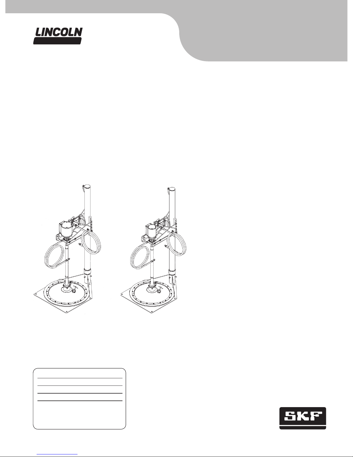
Pump and hoist assembly
Models 275260, V350400HF and V450400HF, series “A”
400 lb.
(181 kg)
drum size, air operated, manually controlled
Installation and maintenance guide
Date of issue October 2014
Form number 404478B
Page A31
Section 21B
Model V450400HF
4 in. (101 mm)
PMV pump with hoist
Model V350400HF
3 in. (72 mm)
PMV pump with hoist

Models V350400HF
and 275260
Description
Model 275260 is a pump hoist (without the
pump) for use with 120 lb. (54 kg) and
400 lb. (181 kg) refinery container drums,
400 lb. (181 kg) follower, and the necessary
hoses and fittings to perform a basic installation († Fig. 1, page 3).
Model V350400HF includes the 275260
pump hoist and follower and a 3 in. (76 mm)
PMV grease pump for use in 400 lb.
(181 kg) container drums.
Model V450400HF includes the 275260
pump hoist and follower and a 4 in.
(102 mm) PMV grease pump for use with
400 lb. (181 kg) container drums.
All models will place a pump and follower
in position for insertion into a standard
400 lb. (181 kg) refinery container. The prim-
ing action of these models is created by
gravity and the vacuum created when material is pumped from the drum. The weight of
the pump and follower, plus the effects of
atmospheric pressure, work with the shape
of the follower, to direct the material into the
pump inlet. The follower will remain on top
of the material until the container is emptied
by the pump. When the follower reaches the
bottom of the container, very little, if any,
material is left in the bottom of the drum.
The follower will work well with most drum
liners in good condition.
Specifications
Unit height, lowered position 60 1/4 in. (1,530 mm)
Unit height, raised position 97.00 in. (2,464 mm)
Hoist capacity 200 lbs. (91 Kg)
Operating pressure (hoist) 40 to 100 psi (3 to 7 bar)
Pump V350400000
Pump ratio 50:1
Pump maximum working pressure 5,000 psi (345 bar) (limited by hose working pressure)
Pump maximum air pressure 125 psi (9 bar)
Air inlet
3
/8 NPT male (3/8 in. ID hose)
Lube outlet
1
/4 NPT male x 84 in. (2,134 mm) (1/4 ID SAE 100R2) hose
Model V450400HF
Specifications
Unit height, lowered position 60 1/4 in. (1,530 mm)
Unit height, raised position 97 in. (2,464 mm)
Hoist capacity 200 lbs. (91 Kg)
Operating pressure (hoist) 40 to 100 psi (3 to 7 bar)
Pump V450400000
Pump ratio 50:1
Pump maximum working pressure 5,000 psi (345 bar) (limited by hose working pressure)
Pump max air pressure 100 psi (7 Bar)
Air inlet
3
/8 NPT male (3/8 in. ID hose)
Lube outlet
1
/4 NPT male x 84 in. (2,134 mm) (1/4 ID SAE 100R2) hose
2
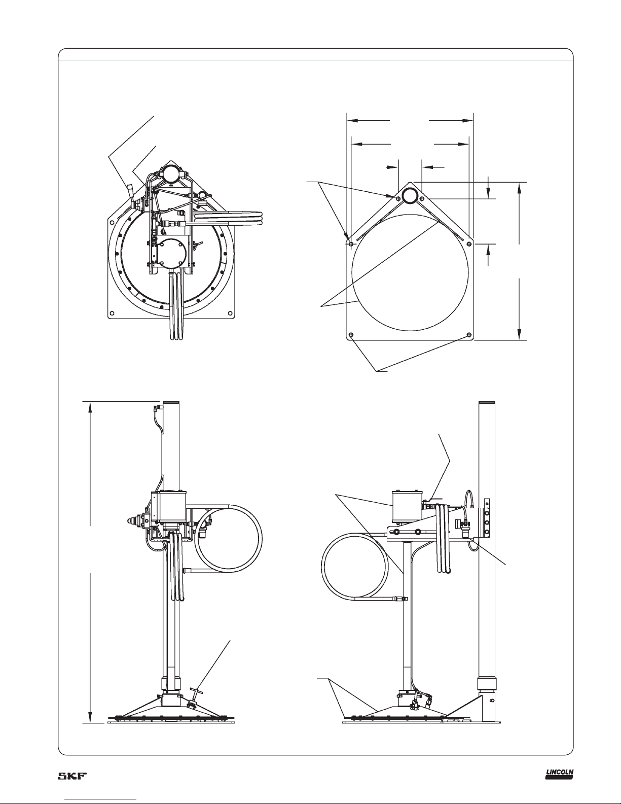
Fig. 1
(10) Hoist control valve
(17) Air assist push button
4 x Ø.69 in. (Ø17 mm)
Mounting holes
23.75 in.
(603 mm)
22.13 in.
(562 mm)
4.44 in.
(113 mm)
8.50 in.
(216 mm)
29.57 in.
(751 mm)
Shipping holes
For pump operating and service instructions, see the
appropriate owner’s manual for each pump.
Model V350400000 († section A5 page 82 series).
Model V450400000 († section A5 page 85 series).
60.25 [1530]
lowered
97.00 [2464]
raised
(21) Air vent
Base mounting detail
V350400000 3 in. (76 mm) pump assembly or
V450400000 4 in. (102 mm) pump assembly
(47) Follower
assembly
(34) Pump air supply valve
(44) Hoist
regulator
3

Fig. 2
Air assist push button.
Hoist control valve shown in
neutral position.
Pump air supply valve.
Remove six bolts, move mount down one set of holes
to position shown. Reinstall bolts, adjust mount to be
level with floor. Tighten bolts securely.
Position pump mount so that follower is aligned
with drum when drum is positioned against
stops at back side of mounting base. Tighten
bolts securely.
Connect length of 1/4 in . (6 mm) OD tubing
between air assist valve (17), and follower as
shown († fig. 3, page 6). Secure pump tube
with two nylon ties.
Left side view
Right side view
4
Installation
1 Select a location where there is adequate
clearance around the hoist to operate
and maneuver around the hoist and
pump assembly when installing and
removing drums.
2 The mounting base must be securely
fastened to the floor before use.
Mounting dimensions are provided on
base mounting detail in fig. 1, page 3 or
the base may be used as a template for
drilling and positioning anchors.
3 After hoist has been secured to the floor
reposition the pump support (46) by
moving it down on the support tube (15)
(† fig. 3, page 6). Adjust the pump sup-
port so that it is parallel to the floor and
secure by tightening the six mounting
bolts (4). This will keep the pump tube
parallel with the support tube.
4 Mount pump to pump mount (29).
The holes in the pump mount are off
center with the pump mount. When the
pump mount is placed in the pump support (46) the pump mount should be
placed with the holes closest to the open
end of the pump support († fig. 3,
page 6). When attaching the pump to
the mount (29) attach pump outlet body
to pump mount with four 1/4–20 x 9/16
hex screw and washer assemblies (39)
(† fig. 3, page 6).
5 Place pump and mount into pump sup-
port (46) and loosely install hex bolts,
lock washers, and flat washers (4, 5, and
6) through slots in support. Leave loose
until final adjustments are made.
6 Assemble air inlet fittings († fig. 3,
page 6). Assemble the air regulator (44)
to the air inlet of the hoist as shown in
the figure. Note that there is a 1/8 in. pipe
plug packaged with each regulator for
plugging the unused gage port in the
regulator. Install this plug into the unused port on the regulator (44) as
shown.
7 Measure and cut a length of the supplied
1
/4 in. OD black polyurethane tubing to
connect the air inlet to the regulator inlet
(† fig. 3, page 6). The tubing will simply
push fit into the 1/4 in. fittings included
with the model.
8 Assemble the air hose to the air coupler
(24). Make sure the ball valve (34) is
closed and the hoist control valve (10) is
in the down position. Attach air hose to
source of filtered, regulated air. The air
pressure should be set initially to about
40 psi (3 bar).
9 Adjust the hoist air regulator (44) for a
pressure of around 30 to 40 psi (2 to
3 bar). Check for air leaks in all connections. Slowly move the hoist control valve
(10) to the raised position and raise
pump so the end of the pump tube will
clear the primer assembly.
10 Attach the primer assembly to the end of
the pump tube. When assembling pump
to the follower, a reducing adapter is
used (38). Apply some grease to the
outside of the adapter and the o-rings
on the inside of the adapter and the
|inside of the follower. Push the adapter
into the follower assembly until it seats
against the shoulder. Tighten the three
hex bolts on the follower (14) securely.
Apply some grease to the end of the
pump tube and slide into the reducing
adapter (38) until the pump tube is flush
with the bottom of the follower. Tighten
the three set screws (32) securely.
Failure to securely fasten the base to the
floor may result in severe injury and or
property damage. Pump hoist may topple over if not securely fastened.
WARNING
11 Raise the follower high enough to clear
an open 400 lb. (181 kg) container.
Place the container under the follower
and slide the drum back on the mounting
base (8) until the bottom is against both
gusset plates on the base. Adjust the
position of the pump with respect to the
drum by sliding the pump mount (29) in
the pump support (46) until the follower
is centered over the open drum.
Tighten the hex bolts (4) through the
slots in the pump support to secure the
pump mount. Do not insert the follow-
er into the drum at this time.
12 Using the remaining polyurethane tub-
ing, attach to the open fitting on the
2-way air valve (17) mounted on the
pump support (46) by pushing one end
of the tube into the fitting until secure.
(† fig. 3, page 6). Thread the tubing
down along the pump tube to the fitting
(1) in the top of the follower assembly.
Secure the tubing to the pump tube with
two nylon wire ties, supplied with the
assembly († fig. 2, page 4).
13 Check for proper air flow by pressing
button on 2-way air valve (17) making
sure that air flows through check valve
(30) and out under follower assembly.
14 Connect fluid hoses to pump outlet.
These models are supplied with a 1/4 in.
(6 mm) ID high pressure hose (40) with
33
/64 in. (13 mm) female thread on both
ends. Two male adapters (45) are supplied to adapt the hose to 1/4 NPT male
for the pump outlet, and working end of
the hose. Insert the hose adapters (45)
into each end of the high pressure hose
and tighten securely for leak proof seal.
Thread one end of the hose into the pump
outlet and tighten securely. Attach the
other end as required for the application.
5
 Loading...