

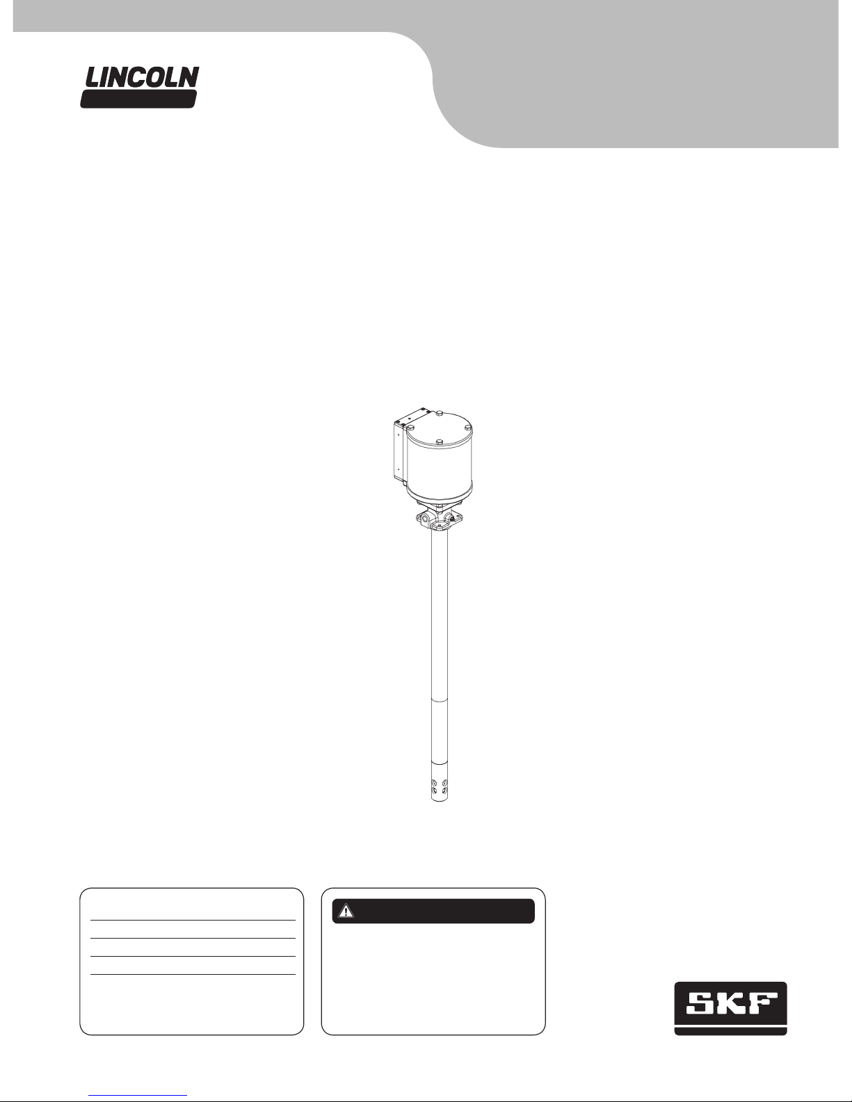
PMV grease pump
Models V450120000 and V450400000, series “A”, 50:1 ratio,
(4.25 in. airmotor)
Installation and maintenance guide
Read manual prior to installation or use
of this product. Keep manual nearby for
future reference. Failure to follow
instructions and safety precautions may
result in death or serious injury.
DANGERDate of issue August 2014
Form number 404137E
Section A5
Page 85E

Explanation of signal
words for safety
Safety
Read and carefully observe these
instructions before installing, operating or
troubleshooting this equipment.
The equipment must be installed, maintained and repaired exclusively by persons
familiar with the instructions.
Install and/or operate the equipment only
after safety instructions and this guide have
been read and are completely understood.
Adequate personal protection must be
used to prevent splashing of material on the
skin or in the eyes.
Always disconnect power source (electricity, air or hydraulic) from the equipment
when it is not being used.
Any other use not in accordance with
instructions will result in loss of claim for
warranty or liability.
• Do not misuse, over-pressurize, modify
parts, use incompatible chemicals, fluids,
or use worn and/or damaged parts.
• Always read and follow the fluid manufac-
turer’s recommendations regarding fluid
compatibility, and the use of protective
clothing and equipment.
• Failure to comply may result in death or
serious injury.
• Adequate personal protection is recom-
mended to prevent splashing of material
on the skin or in the eyes.
• Always disconnect air coupler from pump
when the pump is not being used.
• Always wear eye protection.
Indicates a hazardous situation which,
if not avoided, could result in minor or
moderate injury.
CAUTION
Indicates a hazardous situation which,
if not avoided will result in death or
serious injury.
WARNING
Indicates a hazardous situation which,
if not avoided, will result in death or
serious injury.
DANGER
Safety instruction signs indicate specific
safety-related instructions or
procedures.
SAFETY INSTRUCTION
This is the safety alert symbol. It is used
to alert you to potential physical injury
hazards. Obey all safety messages that
follow this symbol to avoid possible
injury or death.
Contents
Safety ............................2
Explanation of signal words for safety ...2
Owner/operator responsibility .........3
Description ........................3
Appropriate use ....................4
Initial pump priming .................4
Installation ........................5
Bung bushing installation ............5
System start-up ....................5
Pressure relief procedure .............5
Pump repair .......................5
Pump grounding ....................6
Sealant application instructions .......6
Basic pump operation. . . . . . . . . . . . . . . .6
Lincoln industrial
standard warranty .................15
2
Owner/operator
responsibility
It is the owner/operator responsibility to
properly use and maintain this equipment.
The instructions and warnings contained
in this manual shall be read and understood
by the owner/operator prior to operating
this equipment.
It is the owner/operator responsibility to
maintain the legibility of all warning and
instruction labels.
The owner/operator shall retain this
manual for future reference to important
warnings, operating and maintenance
instructions.
Description
Models V450120000 and V450400000 are
air operated double acting grease pumps for
dispensing automotive greases.
Models V450120000 and V450400000
are stub pumps with a 1 1/2 NPT threaded
inlet. It may be mounted in the bung
opening of a grease drum by using an
optional bung bushing and suction tube
(† fig. 1, page 5).
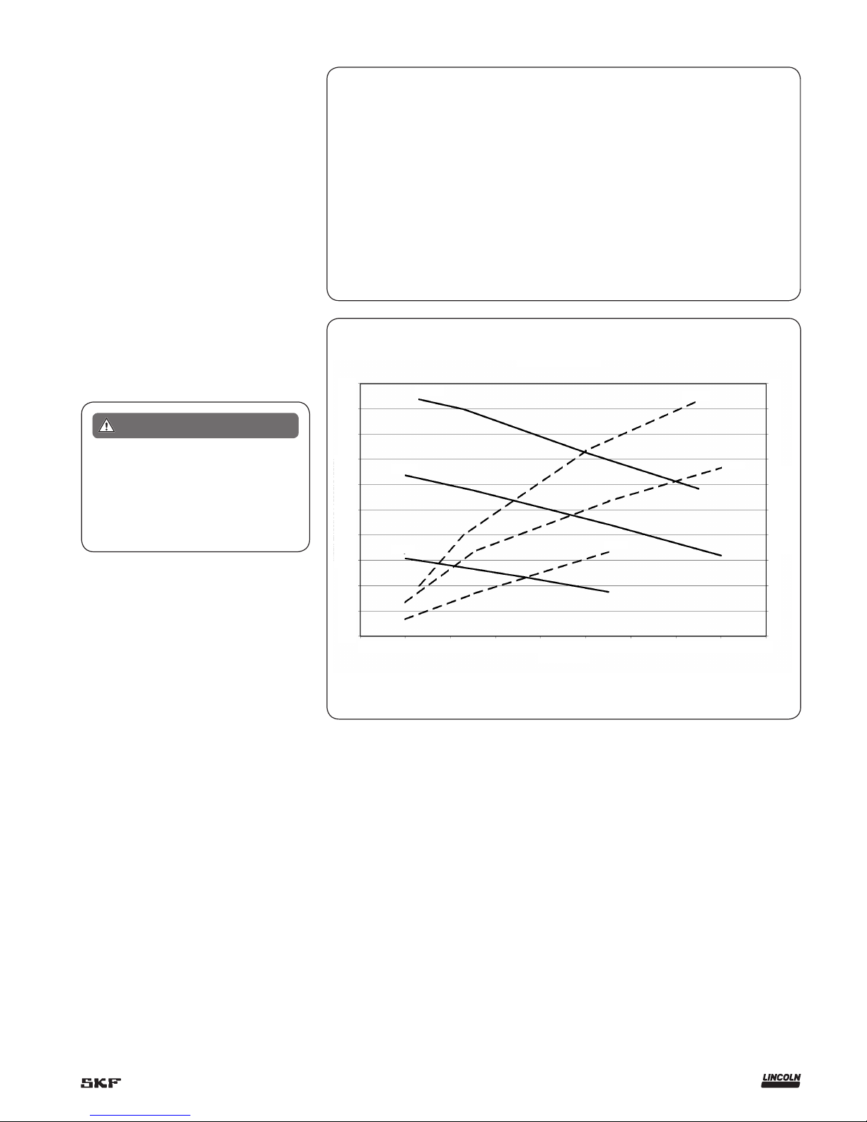
Mean effective pressure [psi (bar)]
5,000
(345)
4,500
(310)
4,000
(276)
3,500
(241)
3,000
(206)
2,500
(172)
2,000
(138)
1,500
(103)
1,000
(69)
500
(34)
0
Air consumption [scfm (m³/min.)]
30
(0.85)
27
(0.76)
24
(0.67)
21
(0.59)
18
(0.5)
15
(0.42)
12
(0.34)
9
(0.25)
6
(0.17)
3
(0.08)
0
Output [lbs/min.(kg/min.)]
0 0.5
(0.23)
1
(0.45)
1.5
(0.68)
2
(0.91)
2.5
(1.13)
3
(1.36)
3.5
(1.59)
4
(1.81)
4.5
(2.04)
100 psi
(6,9 bar)
100 psi
(6,9 bar)
70 psi
(4,8 bar)
70 psi
(4,8 bar)
40 psi
(2,8 bar)
40 psi
(2,8 bar)
If any fluid appears to penetrate the skin,
get emergency medical attention immediately. Do not treat injury as a simple
cut. Tell attending physician exactly what
fluid was injected.
WARNING
Pump specifications
Pumping ration 50:1
Air pressure 40 to 150 psi (2,7 to 10,3 bar)
Maximum operating pressure 7,500 psi (517 bar)
Operating temperature –40 to 150 °F (–40 to 65 °C)
Air inlet
3
/8 in. NPFT
Material outlet
1
/4 in NPTF
Airmotor bore diameter 4.25 in. (108 mm)
Stroke 3.25 in. (82,5 mm)
Output per cycle 1.47 in.³ (24,1 cm³)
Wetted parts Carbon steel, brass, zinc, polyurethane, nitrile
Performance chart
3
Failure to heed the following warnings
may result in personal injury and/or
property damage.
• Always determine the correct air
pressure to operate the lubrication
pump. This pump can develop over
7,500 psi (517 bar). To determine the
air pressure to operate the lubrication
pump, simply divide the rated pressure of the lowest rated component
on the down stream side of the pump
by the lubricant to air pressure ratio of
the pump. Example: The lowest rated
component has a rating of 4,000 psi
(276 bar). If the lubrication pump is a
50:1 pump, divide 4,000 psi (276 bar)
by 50 to determine the correct air
pressure setting, (4,000 psi
(276 bar)/50 = 80 psi (5,5 bar)).
Set the air regulator that controls the
air to the pump to 80 psi (5,5 bar) or
less.
• Never point the control valve at any
part of the body or at another person.
• Never try to stop or deflect material
from the dispensing valve, leaking
connection or component with your
hand.
• Always relieve pressure from the
system before servicing.
• Avoid contact with the nozzle.
WARNING
Appropriate use
The pump is designed to dispense automotive greases directly from the refinery
container. It can be used in a system with
mutiple hose reels and control valves.
Pumps are to be operated with compressed air only. Operation with combustible gasses is prohibited.
Maximum air pressures should not be
exceeded. Failure to heed this warning
may result in serious personal injury,
property damage, and failure of the
pump.
WARNING
Do not use this equipment to pump any
fluids other than the fluids for which it is
designed. Types of fluids not to be
pumped with this equipment include:
• gasoline
• fuel oil
• diesel fuel
• windshield washer solvent
• antifreeze
• brake fluid
• water
Failure to comply may result in serious
personal injury, significant damage to
equipment, and fire or other types of
property damage.
Failure to comply will also result in
loss of claim for warranty or liability.
WARNING
Failure to comply with the warnings listed below may result in serious personal
injury, significant damage to equipment,
and fire or other types of property
damage.
Failure to comply will also result in
loss of claim for warranty or liability.
• Do not alter or modify any part of the
equipment.
Before each use:
• Read and follow fluid manufacturer’s
recommendations regarding fluid
compatibility and use of protective
clothing/equipment.
• Confirm equipment and safety devices
are in place and operating properly.
• Immediately repair or replace any
parts that are found to be worn or
damaged.
• Confirm all grease connections are
tightened securely.
Once system is pressurized:
• Do not attempt to repair, disassemble,
or replace any part of the equipment
without de-pressurizing system first.
• Do not exceed the stated maximum
working pressure of pump or the
lowest pressure-rated component of
the system.
• Do not point dispensing valve at any
part of the body or at another person.
• Do not attempt to block fluid coming
out of dispensing valve, leading
connection, or other component with
any part of the body.
WARNING
Initial pump priming
When the pump is operated for the first
time, the pump will have to be primed.
To prime the pump, remove the grease hose
from the pump lube outlet and set aside.
Connect the airline to the air inlet of the
pump with an air pressure of less than
40 psi (2,76 bar). Slowly increase the air
pressure to the pump until the pump begins
to operate very slowly. Allow the pump to
operate at the slow speed until lubricant
begins to flow out of the pump lube outlet.
After lubricant, free of air begins to flow
from outlet, stop the pump. Attach the high
pressure hose and control valve to the pump
lubricant outlet. Restart the pump and hold
the control valve nozzle in a suitable container while holding the control valve open
to prime the hose and control valve.
Increase the air pressure to the pump as
required, keeping it operating.
4
Installation
Pumps are tested in light oil before shipment. To avoid system contamination, flush
the pump with the lubricant to be dispensed
before installing the pump.
Flush all supply lines, hoses, reels and fittings used in the dispensing system with
mineral spirits or other petroleum based
solvent to remove dirt, chips and other foreign matter that may damage the pump or
other system components. The components
should be blown dry with air after flushing.
Placement of a low restriction shut-off
valve (such as a ball or gate valve) into the
system between the pump outlet and overhead delivery system is recommended.
This will allow the pump to be isolated from
the system and be removed for service.
Lincoln recommends using a filter/regulator (3/8 in. NPT port size) such as a Lincoln
#602136 in the air supply line to the pump
to regulate the air pressure to the pump.
Lincoln does not recommend using Teflon
tape pipe sealant when making connections
to this pump.
Do not use Teflon tape as sealant for
pump connections.
WARNING
Bung bushing
installation
Thread bung bushing into 2 in. NPT bung on
top of reservoir drum or tank.
(† fig. 1) Tighten bung bushing securely
into bung thread. (fig. 1 illustrates a
55-gallon drum; other containers will be
installed in a similar manner.)
!
Notice
Lincoln recommends using a
filter/regulator (3/8 in. NPT port size)
such as a Lincoln #602136 in the air
supply line to regulate the air pressure
to the pump.
System start-up
When operating the pump in a system for
the first time, purge all air from the system
in order for the pump to prime and operate
reliably. Before connecting the pump to a
system, make sure the pump is placed into a
container of the grease that is to be dispensed. Connect a short length of hose to
the pump outlet and direct the open end of
the hose into a container to catch the
grease. Operate the pump at low air pressure, 40 psi (2,7 bar), until the pump
primes, and grease flows smoothly from the
end of the hose.
The system can now be connected to the
pump outlet. Purge the entire system in a
similar manner, slowly pumping grease
through all reels and control valves until
grease, free of air, flows smoothly from each
outlet.
Pressure relief
procedure
The following procedure should be followed
when it becomes necessary to shut the
system down for service or container
changes.
1 Disconnect the air supply from the inlet of
the pump.
2 Bleed the lubricant pressure off the
system by opening a dispensing valve into
a container. Hold the valve open until all
flow from the system stops.
3 Close the shut-off valve between the
pump and reservoir on standpipe
installations (if present).
4 Close the shut-off valve between the
pump outlet and supply lines (if present).
5 Slowly loosen the lubricant supply line at
the pump outlet. A very small volume of
grease will leak from the threads. If
pressure is present, stop the loosening
procedure and repeat steps 1 through 4.
Pump repair
Repair is limited to the service parts listed
on following pages. In most cases, service is
going to be the replacement of soft seals in
the pump († fig. 5 and 6 for internal
components of the pump, and fig. 7 for
internal components if its an air valve
Contact your nearest authorized Lincoln
service dealer or Lincoln technical services
for assistance.
When ordering replacement parts, order
by part number and description. The model
number and series letter may also be
required.
!
Notice
New outlet body and gasket
New outlet body is designed for a
copper gasket. This gasket replaced the
o-ring that was installed on PMV pumps
manufactured prior to December 2013.
Replace o-ring with copper gasket.
5

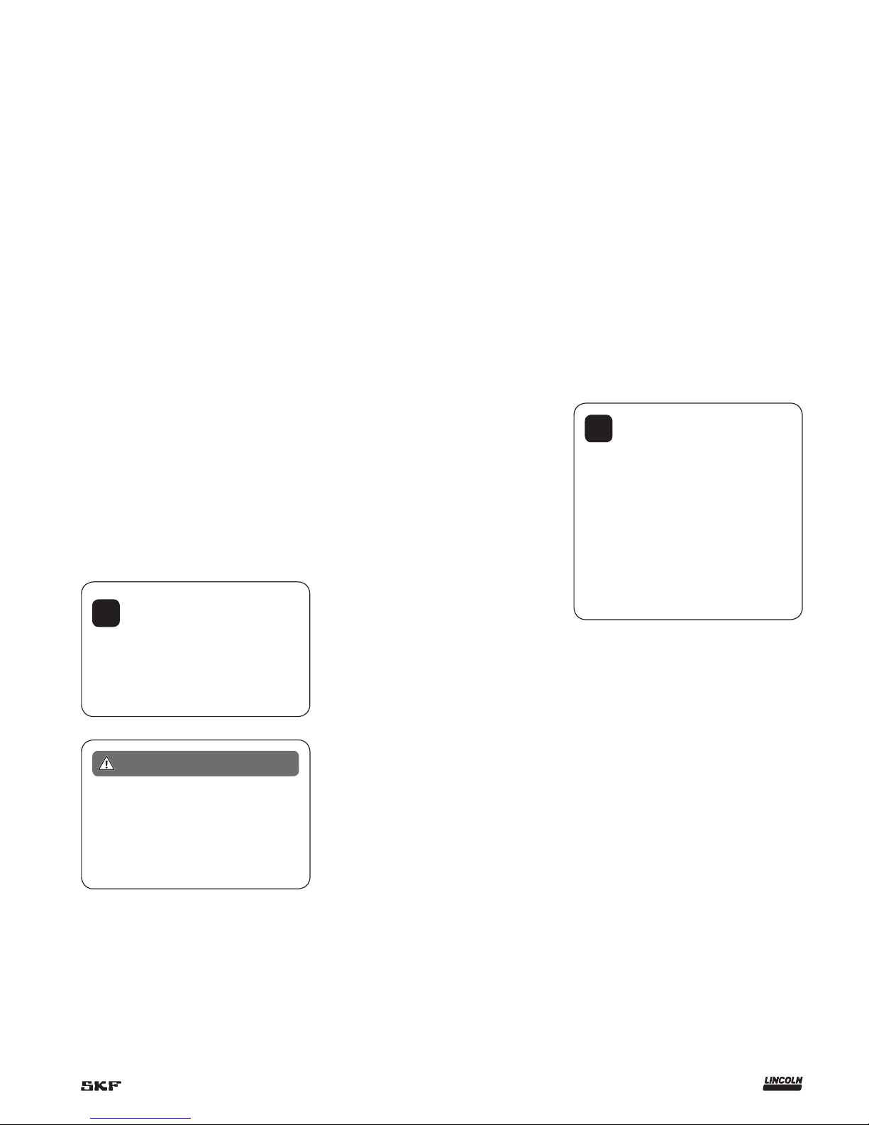
Grounding wire
(user supplied)
Grounding screw
(inclided with pump)
!
Notice
After the pump and hose have
been primed and are free of are, the air
pressure may be increased to the desired operating pressure. Check for leaks
at all connections.
!
Notice
After the pump and hose have
been primed and are free of air, the air
pressure may be increased to the desired operating pressure. Check for leaks
at all connections.
Pump grounding
The pump should be grounded to reduce
static discharge. To ground the pump,
remove the grounding screw from the pump
outlet body and insert the screw through a
ring terminal that has been attached to a
grounding wire.
Securely tighten the screw into the outlet
body. The other end of the ground wire
should be securely connected to a true earth
ground.
Sealant application
instructions
1 Clean and dry all surfaces where sealant
will be applied.
2 Apply small bead of Dow Corning 1437
RTV sealant (or an equivalent sealant)
around end of exhaust cavities where part
(6) is displayed in Figure 4.
3 Reassemble pump.
!
Notice
Allow sealant to dry for 1-2 hours
before applying any air pressure to the
pump.
Basic pump operation
The air pressure should be adjusted so that
the pump can overcome the back pressure
in the lube system. Too much air pressure
can cause the pump to deliver grease very
rapidly, which can damage the equipment
being lubricated.
When the pump is not in operation,
disconnect the air supply to the pump and
relieve all pressure on the control valve and
grease hose († Pressure relief
procedure, below).
Followers are recommended with
lubricants that do not readily seek their own
level, or in cold temperature conditions.
They help by keeping the grease on an even
level and reduce the air pockets that can
form in the grease by the removal of grease
by the pump from the bottom of the
container.
6

4 x / -20 UNC
1
4
2 / in.
(57,2 mm)
1
4
1 / in.
(35 mm)
3
8
/ in. NPTF
Material outlet
1
4
3
4
/ in.
(18 mm)
A
B
2 / in.
(54 mm)
1
8
/ in. NPTF
air inlet
3
8
6 / in.
(166 mm)
1
2
3 / in.
(94 mm)
11
16
3 / in.
(81 mm)
3
16
5 / in.
(143 mm)
5
8
6 in.
(152 mm)
/ in.
(14 mm)
9
16
Exhaust ports
Mounting holes
Material inlet
Pump dimensions
Model numbers Drum size Dimensions A Dimension B
V450120000 120 lbs. (54 kg) 36 7/16 in. (926 mm) 27 3/8 in. (695 mm)
V450400000 400 lbs. (181 kg) 42 15/16 in. (1 091 mm) 33 7/8 in. (860 mm)
7

1
2
Torque to
24 to 30 in.lbf.
(2,7to 3,3 Nm)
4
3
5
Torque to 4 to 5 ft.lbf.
(5,4 to 6,8 Nm)
6
11
7
Apply Loctite 243* (blue)
to threadsTorque to
20 to 22 ft.lbf.
(27,1 to 29,7 Nm)
8
9
10
5
12
13
14
Apply a small bead of Dow Corning 737
RTV sealant or equivalent to top
mating surface of cylinder as shown
by dotted line.
8

16
17
18
19
20
21
22
23
24
25
26
27
28
27
29
30
31
32
33
Apply Loctite 243 (blue).
Torque to 5 to 6 ft.lbs.
(6,8 to 8,1 Nm)
Torque to
150 to 160 ft.lbf.
(203 to 216,9 Nm)
34
Torque to 40 to 44 ft.lbf.
(54 to 59,6 Nm)
35
36
37
38
39
40
41 Apply Loctite 243* (blue).
Torque to 5 to 6 ft.lbs.
(6,8 to 8,1 Nm)
42
Torque to 190 to 200 ft.lbf.
(257 to 271 Nm)*
Torque to 190 to 200 ft.lbf.
(257 to 271 Nm)*
9

Parts list
Item no. Description Qt y. Part no.
1 Socket head screw (M5 x 0.8 x 30 mm) 4 275045
2 Valve bar assembly 1 275408
3 Hex head screw (M8 x 1.25 x 160 mm) 4 275040
4 Cylinder head 1 275050
5 O-ring (nitrile) 2 275038
1)
6 Air cylinder 1 275049
7 Hex head screw (M10 x 1.5 x 30 mm) 1 275035
8 Seal (nitrile) 1 275036
1)
9 O-ring (nitrile) 1 34657
1)
10 Piston 1 275055
11 Muffler element 1 275180
1)
12 Cylinder base 1 275052
13 Hex nut (M8 x 1.25) 4 275032
14 O-ring (nitrile) 1 34309
1)
15 Adapter 1 275127
16 O-ring (nitrile) 1 34314
1)
17 O-ring (nitrile) 1 275096
1)
18 Gland nut 1 275074
19 O-ring (polyurethane) 1 275095
1)
20 U-cup (polyurethane/nitrile) 1 275098
1)
*21 Outlet body and gasket kit 1 278902
22 Hex head screw (M8 x 1.25 x 20 mm) 4 275066
23 Grounding screw (#10-32 x 3/8 in.) 1 275129
24 Gasket, copper 1 278701
1)*
25 Pump tube 1 See tube/rod list
26 Plunger rod 1 275070
27 Spring pin 2 275126
1)
28 Connecting rod 1 See tube/rod list
29 Piston adapter 1 275117
30 Check ball 1 275125
31 U-cup (polyurethane/nitrile) 1 275102
1)
32 Piston body 1 275116
33 O-ring (polyurethane) 1 275122
1)
34 Bushing tube 1 275100
35 Check stop 1 275113
36 U-cup (polyurethane/nitrile) 1 275104
1)*
37 Check 1 275111
38 O-ring (polyurethane) 1 275121
1)
39 Check seat 1 275110
40 Priming plunger 1 275105
41 Priming shovel 1 275106
42 Priming tube 1 275112
1)
Denotes parts supplied in 275403 seal kit
* Indicates change
Tube/rod list
Model number Drum Size Item 24 Item 27
V450120000 120 lbs. (54 kg) 275108 275119
V450400000 400 lbs. (181 kg) 275107 275118
10

Declaration of
conformity as defined
by Machinery Directive
98/37/EG Annex II A
This is to declare that the design of the PMV
50:1 grease pumps (models V450120000
and V450400000) complies with the provisions of Directive 98/37/EG
Applied Standards:
EN 292-1 Safety of Machinery - Basic Concepts, General Principles and Design - Part
1: Basic Terminology, Methodology
EN 292-2 Safety of Machinery - Basic
Concepts, General Principles and Design Part 2: Technical Principles and Specifications - Incorporates amendments 1 (1995)
and 2 (1997)
EN 809 Pumps and Pump Units for Liquids - Common Safety Requirements
EN 349 Safety of Machinery - Minimum
Gaps to Avoid Crushing of Parts of the
Human Body
Troubleshooting
Condition Possible cause Corrective action
Pump does not operate. No air or low air to pump. Make sure air pressure to pump is adequate to
operate pump.
Muffler element (11) clogged. Remove muffler element and clean or replace.
Damaged air valve bar assembly (2). Replace air valve bar assembly.
Erratic operation or short stroking. Pump is not primed. Prime pump († Initial pump priming, page 5.
Insufficient material supply. Refill material supply.
Damaged air valve bar assembly (2). Replace air valve bar assembly.
Pump operates but dispenses material
on only one stroke.
Worn or damaged piston u-cup (31) or piston check
(30 and 32).
Inspect and replace if needed.
Worn or damaged inlet check (37 and 39). Inspect and replace if needed.
Insufficient material supply. Pump is not intaking
enough material to dispense on both strokes.
Check inlet for restrictions. Decrease air
pressure to reduce pump speed.
Pump is operating but not dispensing
material.
Inlet check (37 and 39) is not seating or is damaged. Inspect and replace if needed.
St. Louis, MO 08/14,
Bob Hoefler, Director Product Development and Product Engineering
11

This page intentionally left blank.
12

This page left intentionally blank
13

This page left intentionally blank
14

Lincoln industrial
standard warranty
Standard limited warranty
Lincoln warrants the equipment manufactured and supplied by Lincoln to be free
from defects in material and workmanship
for a period of one (1) year following the
date of purchase, excluding there from any
special, extended, or limited warranty published by Lincoln. If equipment is determined to be defective during this warranty
period, it will be repaired or replaced, within
Lincoln’s sole discretion, without charge.
This warranty is conditioned upon the
determination of a Lincoln authorized representative that the equipment is defective.
To obtain repair or replacement, you must
ship the equipment, transportation charges
prepaid, with proof of purchase to a Lincoln
Authorized Warranty and Service Center
within the warranty period.
This warranty is extended to the original
retail purchaser only. This warranty does not
apply to equipment damaged from accident,
overload, abuse, misuse, negligence, faulty
installation or abrasive or corrosive material,
equipment that has been altered, or equipment repaired by anyone not authorized by
Lincoln. This warranty applies only to equipment installed, operated and maintained in
strict accordance with the written specifications and recommendations provided by
Lincoln or its authorized field personnel.
This warranty is exclusive and is in lieu
of any other warranties, express or
implied, including, but not limited to, the
warranty of merchantability or warranty
of fitness for a particular purpose. War-
ranty on items sold by Lincoln, but not
manufactured by Lincoln are subject to
the warranty consideration, if any, of
their manufacturer (such as hoses,
hydraulic and electric motors, electrical
controllers, etc.) Assistance in making
such warranty claims can be offered as
required.
In no event shall Lincoln be liable for incidental or consequential damages. Lincoln’s
liability for any claim for loss or damages
arising out of the sale, resale or use of any
Lincoln equipment shall in no event exceed
the purchase price. Some jurisdictions do
not allow the exclusion or limitation of incidental or consequential damages, therefore
the above limitation or exclusion may not
apply to you.
This warranty gives you specific legal
rights. You may also have other rights that
vary by jurisdiction.
Customers not located in the Western
Hemisphere or East Asia: Please contact
Lincoln GmbH and Co. Kg, Walldorf,
Germany, for your warranty rights.
Special limited warranties
Special limited 2 year warranty
SL-V series, single injectors – 85772,
85782, and replacement injectors –
85771, 85781
Lincoln warrants the SL-V Injector series to
be free from defects in material and workmanship for two (2) years following the date
of purchase. If an injector model (single or
replacement) is determined to be defective
by Lincoln, in its sole discretion, during this
warranty period, it will be repaired or
replaced, at Lincoln’s discretion, without
charge.
Special limited 5 year warranty
series 20, 25, 40 bare pumps, pmv bare
pumps, heavy duty and 94000 series bare
reels
Lincoln warrants series 20, 25, 40 bare
pumps, PMV bare pumps, heavy duty
(82206), mini bench (81133, 81323), and
all 94000 LFR series (single arm and dual
arm) bare reels to be free from defects in
material and workmanship for five (5) years
following the date of purchase. If equipment
is determined by Lincoln, in its sole discretion, to be defective during the first year of
the warranty period, it will be repaired or
replaced at Lincoln’s discretion, without
charge. In years two (2) and three (3), the
warranty on this equipment is limited to repair with Lincoln paying parts and labor
only. In years four (4) and five (5), the warranty on this equipment is limited to repair
with Lincoln paying for parts only.
Special limited 5 year warranty
limited oil meters, limited fluid control
valves, aod (air-operated diaphragm
pumps)
Lincoln warrants the 712 series control
valves, 912 series lube meters, electronic
lube meters (980, 981, 982 series), our
universal inline digital meters (812/813
series), and our AOD pump offering to be
free from defects in material and workmanship for five (5) years following the date of
purchase. If either is determined to be
defective by Lincoln, in its sole discretion,
during the warranty period, they will be
repaired or replaced, at Lincoln’s discretion,
without charge.
Special DEF (diesel exhaust fluid) limited
warranty
DEF products are warranted to be free from
defects in material and workmanship for a
period of one (1) year following the date of
purchase. The following exceptions to the
standard warranty period are in effect:
• 85700-30/85700-50 DEF hose reels
(bare reel only),
277251/277252 AC DEF pumps, and
277256 and 277257 DEF meters are
warranted for two (2) years from date of
purchase.
• 85623 DEF AOD
(air operated diaphragm) pumps
are covered under the standard five (5)
year AOD pump warranty.
If either is determined to be defective by
Lincoln, in its sole discretion, during the
warranty period, they will be repaired or
replaced, at Lincoln’s discretion, without
charge.
Lincoln Industrial contact information
To find Lincoln Industrial’s nearest service
center call the following number;
customer service 314-679-4200
(international number 01-314-679-4200)
or you may also use our website
www.lincolnindustrial.com
15

® SKF is a registered trademark of the SKF Group.
® Lincoln is a registered trademark of Lincoln Industrial Corp.
Teflon is a registered trademark of DuPont Corporation.
© SKF Group 2014
The contents of this publication are the copyright of the publisher and may not be reproduced (even extracts) unless prior written permission is granted. Every care has been taken to ensure the accuracy of the information contained in this publication but no liability can be
accepted for any loss or damage whether direct, indirect or consequential arising out of the use of the information contained herein.
SKF PUB LS/I1 14331 EN/R1.US · August 2014 · Form 404137E
Seals
Bearings and
housings
Lubrication
systems
Mechatronics Services
The Power of Knowledge Engineering
Combining products, people, and applicationspecific knowledge, SKF delivers innovative
solutions to equipment manufacturers and production facilities in every major industry worldwide. Having expert ise in multiple competence
areas supports SKF Life Cycle Management, a
proven approach to improv ing equipment reliability, optimizing operational and energy efficiency
and reducing total cost of ownership.
These competence areas include bearings and
units, seals, lubrication systems, mecha tronics,
and awide range of services, from 3-D computer
modelling to cloud-based condition monitoring
and asset management services.
SKF’s global footprint provides SKF customers
with uniform quality standards and worldwide
product availability. Our local presence provides
direct access to the experience, knowledge and
ingenuity of SKF people.
lincolnindustrial.com skf.com/lubrication
 Loading...