

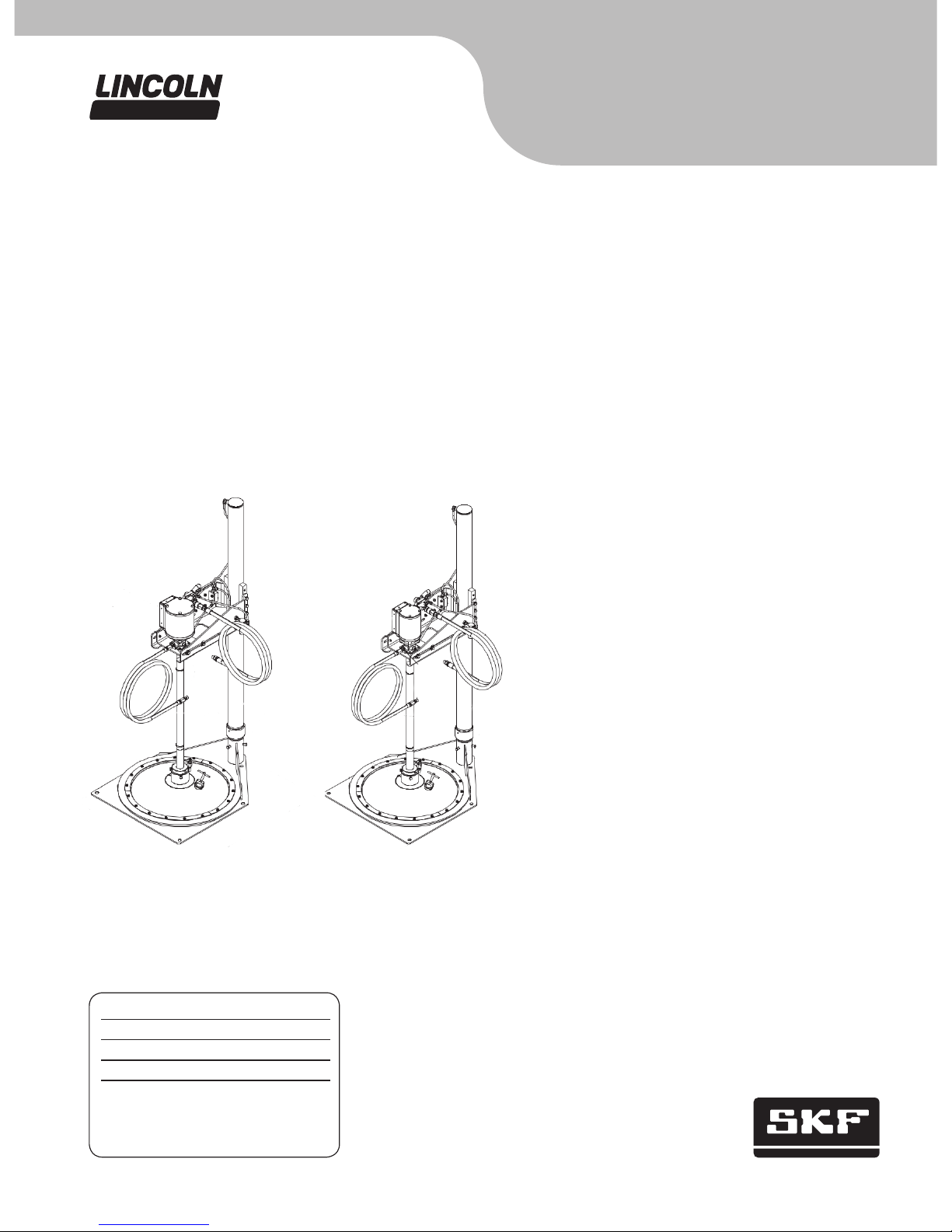
Pump and hoist assembly
Models 275260, V350400HF and V450400HF, series “A”
400 lb.
(181 kg)
drum size, air operated, manually controlled
Installation and maintenance guide
Date of issue October 2014
Form number 404478B
Page A31
Section 21B
Model V450400HF
4 in. (101 mm)
PMV pump with hoist
Model V350400HF
3 in. (72 mm)
PMV pump with hoist

Models V350400HF
and 275260
Description
Model 275260 is a pump hoist (without the
pump) for use with 120 lb. (54 kg) and
400 lb. (181 kg) refinery container drums,
400 lb. (181 kg) follower, and the necessary
hoses and fittings to perform a basic installation († Fig. 1, page 3).
Model V350400HF includes the 275260
pump hoist and follower and a 3 in. (76 mm)
PMV grease pump for use in 400 lb.
(181 kg) container drums.
Model V450400HF includes the 275260
pump hoist and follower and a 4 in.
(102 mm) PMV grease pump for use with
400 lb. (181 kg) container drums.
All models will place a pump and follower
in position for insertion into a standard
400 lb. (181 kg) refinery container. The prim-
ing action of these models is created by
gravity and the vacuum created when material is pumped from the drum. The weight of
the pump and follower, plus the effects of
atmospheric pressure, work with the shape
of the follower, to direct the material into the
pump inlet. The follower will remain on top
of the material until the container is emptied
by the pump. When the follower reaches the
bottom of the container, very little, if any,
material is left in the bottom of the drum.
The follower will work well with most drum
liners in good condition.
Specifications
Unit height, lowered position 60 1/4 in. (1,530 mm)
Unit height, raised position 97.00 in. (2,464 mm)
Hoist capacity 200 lbs. (91 Kg)
Operating pressure (hoist) 40 to 100 psi (3 to 7 bar)
Pump V350400000
Pump ratio 50:1
Pump maximum working pressure 5,000 psi (345 bar) (limited by hose working pressure)
Pump maximum air pressure 125 psi (9 bar)
Air inlet
3
/8 NPT male (3/8 in. ID hose)
Lube outlet
1
/4 NPT male x 84 in. (2,134 mm) (1/4 ID SAE 100R2) hose
Model V450400HF
Specifications
Unit height, lowered position 60 1/4 in. (1,530 mm)
Unit height, raised position 97 in. (2,464 mm)
Hoist capacity 200 lbs. (91 Kg)
Operating pressure (hoist) 40 to 100 psi (3 to 7 bar)
Pump V450400000
Pump ratio 50:1
Pump maximum working pressure 5,000 psi (345 bar) (limited by hose working pressure)
Pump max air pressure 100 psi (7 Bar)
Air inlet
3
/8 NPT male (3/8 in. ID hose)
Lube outlet
1
/4 NPT male x 84 in. (2,134 mm) (1/4 ID SAE 100R2) hose
2
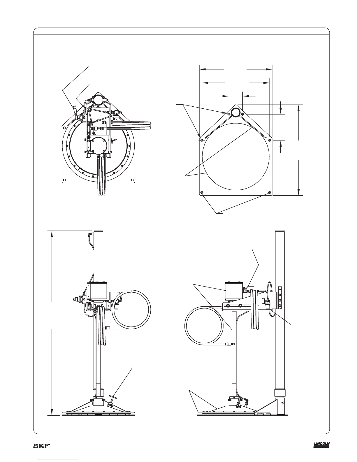
Fig. 1
(10) Hoist control valve
(17) Air assist push button
4 x Ø.69 in. (Ø17 mm)
Mounting holes
23.75 in.
(603 mm)
22.13 in.
(562 mm)
4.44 in.
(113 mm)
8.50 in.
(216 mm)
29.57 in.
(751 mm)
Shipping holes
For pump operating and service instructions, see the
appropriate owner’s manual for each pump.
Model V350400000 († section A5 page 82 series).
Model V450400000 († section A5 page 85 series).
60.25 [1530]
lowered
97.00 [2464]
raised
(21) Air vent
Base mounting detail
V350400000 3 in. (76 mm) pump assembly or
V450400000 4 in. (102 mm) pump assembly
(47) Follower
assembly
(34) Pump air supply valve
(44) Hoist
regulator
3

Fig. 2
Air assist push button.
Hoist control valve shown in
neutral position.
Pump air supply valve.
Remove six bolts, move mount down one set of holes
to position shown. Reinstall bolts, adjust mount to be
level with floor. Tighten bolts securely.
Position pump mount so that follower is aligned
with drum when drum is positioned against
stops at back side of mounting base. Tighten
bolts securely.
Connect length of 1/4 in . (6 mm) OD tubing
between air assist valve (17), and follower as
shown († fig. 3, page 6). Secure pump tube
with two nylon ties.
Left side view
Right side view
4

Installation
1 Select a location where there is adequate
clearance around the hoist to operate
and maneuver around the hoist and
pump assembly when installing and
removing drums.
2 The mounting base must be securely
fastened to the floor before use.
Mounting dimensions are provided on
base mounting detail in fig. 1, page 3 or
the base may be used as a template for
drilling and positioning anchors.
3 After hoist has been secured to the floor
reposition the pump support (46) by
moving it down on the support tube (15)
(† fig. 3, page 6). Adjust the pump sup-
port so that it is parallel to the floor and
secure by tightening the six mounting
bolts (4). This will keep the pump tube
parallel with the support tube.
4 Mount pump to pump mount (29).
The holes in the pump mount are off
center with the pump mount. When the
pump mount is placed in the pump support (46) the pump mount should be
placed with the holes closest to the open
end of the pump support († fig. 3,
page 6). When attaching the pump to
the mount (29) attach pump outlet body
to pump mount with four 1/4–20 x 9/16
hex screw and washer assemblies (39)
(† fig. 3, page 6).
5 Place pump and mount into pump sup-
port (46) and loosely install hex bolts,
lock washers, and flat washers (4, 5, and
6) through slots in support. Leave loose
until final adjustments are made.
6 Assemble air inlet fittings († fig. 3,
page 6). Assemble the air regulator (44)
to the air inlet of the hoist as shown in
the figure. Note that there is a 1/8 in. pipe
plug packaged with each regulator for
plugging the unused gage port in the
regulator. Install this plug into the unused port on the regulator (44) as
shown.
7 Measure and cut a length of the supplied
1
/4 in. OD black polyurethane tubing to
connect the air inlet to the regulator inlet
(† fig. 3, page 6). The tubing will simply
push fit into the 1/4 in. fittings included
with the model.
8 Assemble the air hose to the air coupler
(24). Make sure the ball valve (34) is
closed and the hoist control valve (10) is
in the down position. Attach air hose to
source of filtered, regulated air. The air
pressure should be set initially to about
40 psi (3 bar).
9 Adjust the hoist air regulator (44) for a
pressure of around 30 to 40 psi (2 to
3 bar). Check for air leaks in all connections. Slowly move the hoist control valve
(10) to the raised position and raise
pump so the end of the pump tube will
clear the primer assembly.
10 Attach the primer assembly to the end of
the pump tube. When assembling pump
to the follower, a reducing adapter is
used (38). Apply some grease to the
outside of the adapter and the o-rings
on the inside of the adapter and the
|inside of the follower. Push the adapter
into the follower assembly until it seats
against the shoulder. Tighten the three
hex bolts on the follower (14) securely.
Apply some grease to the end of the
pump tube and slide into the reducing
adapter (38) until the pump tube is flush
with the bottom of the follower. Tighten
the three set screws (32) securely.
Failure to securely fasten the base to the
floor may result in severe injury and or
property damage. Pump hoist may topple over if not securely fastened.
WARNING
11 Raise the follower high enough to clear
an open 400 lb. (181 kg) container.
Place the container under the follower
and slide the drum back on the mounting
base (8) until the bottom is against both
gusset plates on the base. Adjust the
position of the pump with respect to the
drum by sliding the pump mount (29) in
the pump support (46) until the follower
is centered over the open drum.
Tighten the hex bolts (4) through the
slots in the pump support to secure the
pump mount. Do not insert the follow-
er into the drum at this time.
12 Using the remaining polyurethane tub-
ing, attach to the open fitting on the
2-way air valve (17) mounted on the
pump support (46) by pushing one end
of the tube into the fitting until secure.
(† fig. 3, page 6). Thread the tubing
down along the pump tube to the fitting
(1) in the top of the follower assembly.
Secure the tubing to the pump tube with
two nylon wire ties, supplied with the
assembly († fig. 2, page 4).
13 Check for proper air flow by pressing
button on 2-way air valve (17) making
sure that air flows through check valve
(30) and out under follower assembly.
14 Connect fluid hoses to pump outlet.
These models are supplied with a 1/4 in.
(6 mm) ID high pressure hose (40) with
33
/64 in. (13 mm) female thread on both
ends. Two male adapters (45) are supplied to adapt the hose to 1/4 NPT male
for the pump outlet, and working end of
the hose. Insert the hose adapters (45)
into each end of the high pressure hose
and tighten securely for leak proof seal.
Thread one end of the hose into the pump
outlet and tighten securely. Attach the
other end as required for the application.
5

Fig. 3
48*
45
9
2
7
1
44
42
4
5
6
39
40
43
46
41
2
1
36
35
37
33
34
33
24
Reposition pump support (46)
by moving down one hole on
support tube (15) as
shown. Top holes sould be
visible above the pump support.
Plug (packed with 44)
Right rear detail
Attach tubing from follower to open
tube fitting on bottom of air assist valve
(17) as shown.
Position pump mount (29) with edge
closest to holes facing to the front
.
Right front detail
Not shown
Hoist regulator
29
*Indicates change.
6

Operating controls
Refer to fig. 1, page 3.
Hoist control valve (10)
Three position air valve used to raise and
lower the pump into and out of the drum.
When the handle is moved up, the hoist will
raise. When placed in the neutral position,
with handle level with floor, hoist will stop
and hold position. When the handle is placed
in down position, the hoist will lower the
pump into the drum.
Air assist push button (17)
Two-way air valve used to force air under
the follower assembly to assist in lifting the
pump and follower from the drum. The air
assist is used in conjunction with the hoist
control valve when removing the pump and
follower from the drum.
Air vent (21)
Used to vent air trapped under the follower
plate when the follower and pump is lowered into the drum. This valve should be
open when the pump and follower are lowered into the drum. Air will escape from the
valve as the follower is lowered into the
drum. After the follower rests on top of the
lubricant, the valve is closed by turning
clockwise to seal the ball against the seat.
Hoist regulator (44)
Used to control the air pressure to the hoist
only. The air pressure should be set to the
necessary pressure required to raise the
pump and follower. Too much pressure will
cause the hoist to rise very quickly and may
damage the hoist.
Pump air supply valve (34)
Used to control air to the air motor and
pump assembly. When the pump is in
operation this valve must be open to allow
air to flow to the air motor. When servicing,
relieving pressure or operating the hoist,
this valve must be closed to stop air motor
and pump operation when the pump is
removed from the drum.
Operation
Before operating, ensure that the hoist is
securely fastened to the floor. All connecting
bolts must be tightened securely. Air connections and tube fittings are all tight and
leak proof. Fluid connections are tight and
leak proof.
All fluid and air hoses are to be connected
as required.
Installing a material drum
1 Adjust the hoist regulator (44) to about
30 psi (2 bar). Move the hoist control
valve (10) to the raise position to lift the
pump clear of the rim of the drum. Adjust
the hoist regulator as required to a pressure high enough to raise the pump clear
of the drum with out rapid uncontrolled
rising of the pump. Move the hoist control valve to the neutral position to hold
the pump in position.
2 Position the drum of lubricant on the
mounting base (8) so that the drum rests
against both gussets on the back side of
the base.
3 Adjust, if necessary, the location of the
pump support (29) to center the follower
assembly over the top of the drum.
Tighten the bolts (4) if an adjustment
was made.
4 Open the air vent (21) to allow air to vent
from below the follower as the follower is
lowered into the drum.
5 Move the hoist control valve (10) to the
down position and guide the follower into
the drum of lubricant. As the follower is
lowered into the drum, air will vent from
the vent valve. Continue to lower the
pump and follower into the drum until it
stops. Some lubricant may appear at the
vent valve as it is lowered into the drum.
This is normal. Close the air vent (21)
after the follower stops moving.
6 Leave the hoist control valve in the
down position at all times except
when removing the follower from the
drum. This will allow the follower to drop
as the lubricant is depleted from the
drum.
7 Turn on the pump air supply valve (34)
and adjust the air pressure to the air
motor and pump tube assembly to prime
the pump as required. Refer to the owner’s manual for the air motor and pump
tube.
8 While in operation, as the pump removes
material from the drum, the pump will
continue to drop into the drum, following
the level of material down to the bottom
of the drum. Note that air pressure is not
used to exert force on the pump hoist to
force the follower into the drum.
Removing a material drum
When the pump follower reaches the bottom of the drum and drum replacement is
necessary the pump may be removed from
the drum as follows:
1 Close the pump air supply valve (34) to
stop the pump.
2 Move the hoist control valve (10) to the
raise position, and press the air assist
push button (17) at the same time.
3 Hold the base of the drum into the slots
formed in the gussets on the mounting
base with one foot while raising the
pump from the drum.
4 Modulate the hoist control valve and air
assist push button as necessary to work
the follower out of the drum. If the follower hangs up at the drum chimes, it
may help to allow the drum to rise off the
base slightly and allow the air assist to
force the drum off the follower while
guiding the drum by hand.
5 When the follower reaches the top of the
drum, release the air assist push button,
and place the hoist control valve in the
neutral position to hold the pump in
position while the drum is replaced.
6 After removing the drum, remove any
grease from the bottom side of the follower in the area of the air vent check
ball (22), so that air will flow freely
through the vent and grease is not forced
on top of the follower when placing the
follower back into the lubricant.
7

Air cylinder service
The pump must be removed from the hoist
to service the air cylinder assembly.
1 Disconnect all air lines between the pump
and hoist assembly.
2 Disconnect the air line to the follower as-
sembly. The pump and pump mount (29)
and the follower assembly, can be removed
as a unit from the pump support (46) by
removing the four attachment hex bolts,
and washers, (4, 5, and 6). Place the
pump and follower on large sheet of clean
paper or cardboard to keep follower clean.
3 Loosen set screw (12), and remove tube
cap (11) from upper support tube (15).
4 Slide the upper support tube off of the
lower support tube (18) and set aside.
5 The seal (20) is accessible and may be
replaced by removing from the piston (19)
and replacing with a new seal.
6 Carefully inspect the condition of the
upper support tube (15) before reassembly, checking for scratches or damage to
the inside surface. Before re-assembly,
apply a liberal coating of grease to the
inside surface of the upper support tube
(15), piston (19), and seal (20).
7 Reassemble in the reverse order of disas-
sembly. Check all tubing and connections
for leaks.
Service
When service is required see the appropriate
owner’s manual for the pump. Service on
the hoist is limited to the hoist air cylinder
assembly and the follower assembly. All other
hoist components are not serviceable items.
Before any service is attempted it is
important to disconnect the air supply to
the pump and hoist unit and bleed off all
material pressure from the pump outlet
and attached hoses.
WARNING
Follower service
The follower must be removed from the
bottom of the pump for service. The pump
does not need to be removed from the hoist.
1 To remove the follower, remove the
pump and follower from the material
drum.
2 Remove the drum from the base of the
hoist.
3 Lower the pump and follower to the base
on top of a piece of clean cardboard or
paper.
4 Place hoist control valve in neutral
position.
5 Disconnect the air line from the follower.
6 Loosen the three screws (14 or 32) and
slide the follower off the end of the pump
tube. The follower may be tight due to
the O-ring seals (25 or 31) around the
pump tube.
7 Place follower on clean flat surface with
air vent and pump tube bushing facing
the top side.
8 Remove the 18 hex screws (26), three
segment rings (27) and follower wiper
ring (28).
9 Inspect all components for wear or dam-
age, replacing any damaged or worn
components.
10 Re-assembly is the reverse of the disas-
sembly process. When installing the hex
screws (26) take care not to tighten too
tight. The screws only need to be tight
enough to seal the wiper to the follower.
There should be no deflection to the segment rings (27) when the screws are
tightened.
11 Check for leaks and test after
re-assembly.
Air vent service
The air vent (21, 22, and 23) may be
serviced without removing the pump or the
follower from the pump. The pump and
follower must be removed from the drum.
1 Lower the pump and follower to the base
on top of a piece of clean cardboard or
paper.
2 Place hoist control valve in neutral
position.
3 Remove the valve screw assembly (21)
by turning counterclockwise.
4 Remove the retaining ring (23).
5 The ball can now be removed through the
slots on the sides of the valve body.
6 Inspect the ball for any signs of wear or
damage. Replace as necessary. Clean and
inspect the valve body and follower surfaces where the ball is seated. Repair or
replace as necessary.
7 Reassemble in the reverse order of disas-
sembly. Do not tighten the valve screw too
tightly. It should only be tight enough to
form a seal. If tightened too tightly, damage to the ball may occur.
8

Fig. 4
15
19
20
16
17
1
46
1
/4 in. (6mm) OD tubing as
required. Attach to follower.
18
11
12
14
7
1
2
8
9
10
13
Plug, install in bottom
port of 4-way valve.
4 and 5
3
1
2
1
9

Fig. 5
Primer assembly detail
14
32
31
25
38
22
21
23
26
27
28
1
1)
PowerMaster pump.
2)
PMV pump.
1)
1)
2)
2)
10

Parts list
Item Description Part no. Quantity. Item Description Part no. Quantity.
1
1
/4 in. (6 mm) OD x 1/4 in. NPT
(external) 90° ell
247761 7 25 O-ring (nitrile) 343371)2
2
1
/4 in. (6 mm) OD x 0.160 in.
(4 mm) ID polyurethane tubing
– As
required
26
1
/4–20 x 5/8 in. tapping screw 274648 18
3
1
/4–20 x 1 3/4 socket head cap screw 50779 4 27 Follower segment 274644 3
4
3
/8–16 x 1 hex head cap screw 50044 10 28 Wiper ring (nitrile) 34371 1
5
3
/8 in. split lock washer 66220 10 29 Pump mount 274734 1
6
3
/8 in. flat washer 48268 4 30 Check valve 274653 1
7
1
/4–20 hex nut 51010 6 31 O-ring 342622)2
8 Mounting base 274661 1 32
5
/16–18 x 1/2 in. cup point set screw 505252)3
9
1
/4 in. (6 mm) external run tee 274654 1 33
3
/8 in. (9 mm) hex nipple 10540 2
10 4-way air valve 237588 1 34
3
/8 in. (9 mm) ball valve, 1/4 turn 275291 1
11 Tube cap 274719 1 35
3
/8 in. (9 mm) tee 70159 1
12 #10–32 x 1/4 in. cup point set screw 50522 1 36
3
/8 NPT x 1/4 NPT bushing 275290 1
13
1
/4 NPT pipe plug 67359 1 37 Air nipple 640106 1
14
5
/16–18 x 3/4 in. hex head cap screw 500161)6 38 Follower adapter (includes 31 and 32) 275259 1
15 Upper support tube 274666 1 39
1
/4–20 x 9/16 hex screw
& washer assembly
50060 4
16
1
/4–20 x 1 1/2 socket head cap screw 50051 2 40
1
/4 x 84 in. (6 x 2,134 mm) high pressure
hose
75084 1
17 2-way air valve 274682 1 41
1
/4 NPT hex nipple 10462 1
18 Lower support tube 274664 1 42 Air pressure gage 247843 1
19 Piston 274663 1 43
3
/8 x 84 in. (9 x 2,134 mm) air hose 275289 1
20 Piston seal 34327 1 44 Mini air regulator 602003 1
21 Valve screw assembly 274651 1 45 Hose connector 10198 2
22 1 in. (25 mm) ball 274715 1 46 Pump support 274669 1
23 Retaining ring 274650 1 47 400 lb (181 kg) follower assembly 274655 1
24 Air coupler 242563 1 48 Check valve 1/4 NPT 245868* 1
1)
PowerMaster pump.
2)
PMV pump.
*Indicates change.
11

This page intentionally left blank.
12

This page intentionally left blank.
13

This page left intentionally blank.
14

15
Lincoln industrial
standard warranty
Standard limited warranty
Lincoln warrants the equipment manufactured and supplied by Lincoln to be free
from defects in material and workmanship
for a period of one (1) year following the
date of purchase, excluding there from any
special, extended, or limited warranty published by Lincoln. If equipment is determined to be defective during this warranty
period, it will be repaired or replaced, within
Lincoln’s sole discretion, without charge.
This warranty is conditioned upon the
determination of a Lincoln authorized representative that the equipment is defective.
To obtain repair or replacement, you must
ship the equipment, transportation charges
prepaid, with proof of purchase to a Lincoln
Authorized Warranty and Service Center
within the warranty period.
This warranty is extended to the original
retail purchaser only. This warranty does not
apply to equipment damaged from accident,
overload, abuse, misuse, negligence, faulty
installation or abrasive or corrosive material,
equipment that has been altered, or equipment repaired by anyone not authorized by
Lincoln. This warranty applies only to equipment installed, operated and maintained in
strict accordance with the written specifications and recommendations provided by
Lincoln or its authorized field personnel.
This warranty is exclusive and is in lieu
of any other warranties, express or
implied, including, but not limited to, the
warranty of merchantability or warranty
of fitness for a particular purpose. War-
ranty on items sold by Lincoln, but not
manufactured by Lincoln are subject to
the warranty consideration, if any, of
their manufacturer (such as hoses,
hydraulic and electric motors, electrical
controllers, etc.) Assistance in making
such warranty claims can be offered as
required.
In no event shall Lincoln be liable for inci-
dental or consequential damages. Lincoln’s
liability for any claim for loss or damages
arising out of the sale, resale or use of any
Lincoln equipment shall in no event exceed
the purchase price. Some jurisdictions do
not allow the exclusion or limitation of incidental or consequential damages, therefore
the above limitation or exclusion may not
apply to you.
This warranty gives you specific legal
rights. You may also have other rights that
vary by jurisdiction.
Customers not located in the Western
Hemisphere or East Asia: Please contact
Lincoln GmbH and Co. Kg, Walldorf,
Germany, for your warranty rights.
Special limited warranties
Special limited 2 year warranty
sl-v series, single injectors-85772,
85782, and replacement injectors-85771,
85781
Lincoln warrants the SL-V Injector series to
be free from defects in material and workmanship for two (2) years following the date
of purchase. If an injector model (single or
replacement) is determined to be defective
by Lincoln, in its sole discretion, during this
warranty period, it will be repaired or replaced, at Lincoln’s discretion, without
charge.
Special limited 5 year warranty
series 20, 25, 40 bare pumps, pmv bare
pumps, heavy duty and 94000 series bare
reels
Lincoln warrants series 20, 25, 40 bare
pumps, PMV bare pumps, heavy duty
(82206), mini bench (81133, 81323), and
all 94000 LFR series (single arm and dual
arm) bare reels to be free from defects in
material and workmanship for five (5) years
following the date of purchase. If equipment
is determined by Lincoln, in its sole discretion, to be defective during the first year of
the warranty period, it will be repaired or
replaced at Lincoln’s discretion, without
charge. In years two (2) and three (3), the
warranty on this equipment is limited to repair with Lincoln paying parts and labor
only. In years four (4) and five (5), the warranty on this equipment is limited to repair
with Lincoln paying for parts only.
Special limited 5 year warrantylimited oil meters, limited fluid control
valves, aod (air-operated diaphragm pumps)
Lincoln warrants the 712 series control
valves, 912 series lube meters, electronic
lube meters (980. 981, 982 series), our
universal inline digital meters (812/813
series), and our AOD pump offering to be
free from defects in material and workmanship for five (5) years following the date of
purchase. If either is determined to be
defective by Lincoln, in its sole discretion,
during the warranty period, they will be
repaired or replaced, at Lincoln’s discretion,
without charge.
Special DEF (diesel exhaust fluid) limited
warranty
DEF products are warranted to be free from
defects in material and workmanship for a
period of one (1) year following the date of
purchase. The following exceptions to the
standard warranty period are in effect:
• 85700-30/85700-50 DEF hose reels
(bare reel only),
277251/277252 AC DEF pumps, and
277256 and 277257 DEF meters are
warranted for two (2) years from date of
purchase.
• 85623 DEF AOD
(air operated diaphragm) pumps
are covered under the standard five (5)
year AOD pump warranty.
If either is determined to be defective by
Lincoln, in its sole discretion, during the
warranty period, they will be repaired or
replaced, at Lincoln’s discretion, without
charge.
Lincoln Industrial contact information
To find Lincoln Industrial’s nearest service
center call one of the following number;
customer service 314-679-4200
or you may also use our website
www.lincolnindustrial.com

® SKF is a registered trademark of the SKF Group.
® Lincoln is a registered trademark of Lincoln Industrial Corp.
© SKF Group 2014
The contents of this publication are the copyright of the publisher and may not be reproduced (even extracts) unless prior written permission is granted. Every care has been taken to ensure the accuracy of the information contained in this publication but no liability can be
accepted for any loss or damage whether direct, indirect or consequential arising out of the use of the information contained herein.
SKF PUB LS/I4 15242 EN.R1 · November 2014 · Form 404478B
Seals
Bearings and
housings
Lubrication
systems
Mechatronics Services
The Power of Knowledge Engineering
Combining products, people, and applicationspecific knowledge, SKF delivers innovative
solutions to equipment manufacturers and production facilities in every major industry worldwide. Having expert ise in multiple competence
areas supports SKF Life Cycle Management, a
proven approach to improv ing equipment reliability, optimizing operational and energy efficiency
and reducing total cost of ownership.
These competence areas include bearings and
units, seals, lubrication systems, mecha tronics,
and awide range of services, from 3-D computer
modelling to cloud-based condition monitoring
and asset management services.
SKF’s global footprint provides SKF customers
with uniform quality standards and worldwide
product availability. Our local presence provides
direct access to the experience, knowledge and
ingenuity of SKF people.
lincolnindustrial.com skf.com/lubrication
 Loading...