

Page 1
Subject to modifications
User Manual
Operating Instructions
2.2EN-20001-J11
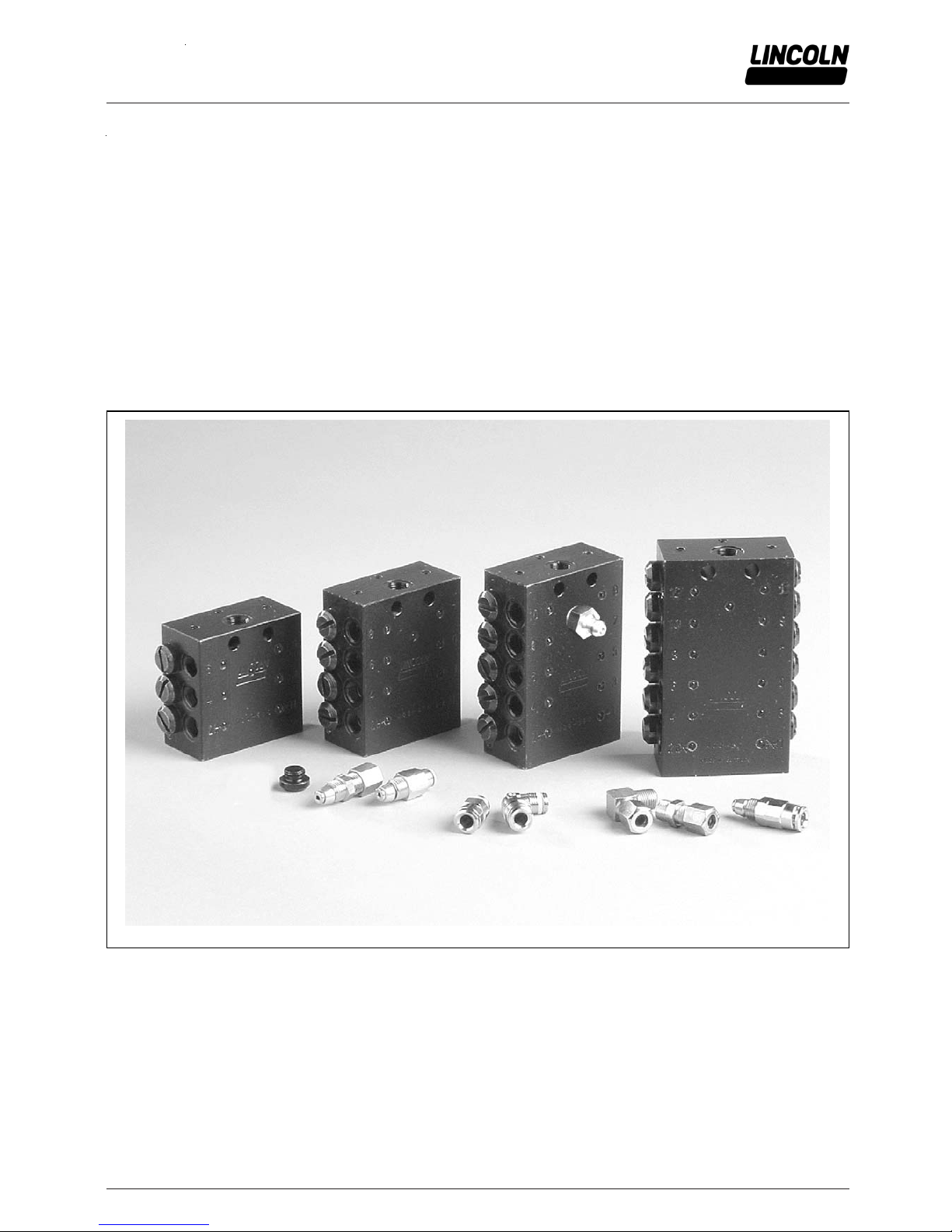
Quicklub - Progressive Metering Devices
for Grease and Oil
Model SSV, SSV-E and SSV M
B-SSV-000a11
SKF Lubrication Systems Germany GmbH ● Heinrich Hertz-Str. 2-8 D-69190 Walldorf Tel. +49(0) 6227 33-0 ● Fax: +49 (0) 6227 33-259
Page 2

P 2 f 2
Subject to modifications
User Manual
Operating Instructions
2.2EN-20001-J11
SKF Lubrication Systems Germany GmbH ● Heinrich Hertz-Str. 2-8 D-69190 Walldorf Tel. +49(0) 6227 33-0 ● Fax: +49 (0) 6227 33-259
Page 3

P 3 f 24
Subject to modifications
User Manual
Operating Instructions
2.2EN-20001-J11
Table of Contents
Page
Introduction
Explanation of Symbols Used ........................................... 4
User’s Responsibility ........................................................ 4
Environmental Protection .................................................. 4
Service ............................................................................. 4
Safety instructions
Appropriate Use ............................................................... 5
General Safety Instructions ............................................... 5
Accident Prevention Regulations ...................................... 5
Operation, Maintenance, Repair ....................................... 5
Installation ........................................................................ 5
Installation
Tube Fittings, Screw-Type ................................................ 6
Main- and secondary Metering devices ........................ 6
Tube Fittings, Push-in Type .............................................. 6
Metering Devices ......................................................... 6
Check Valv es .............................................................. 6
Connection of the High-pressure Hose and
the Pressure Plastic Tube ........................................... 7
Pressure Plastic Tubes and High-pressure Hoses ............ 8
Description
Progressiv e Metering Dev ices Model SSV, SSV-E
and SSV M ....................................................................... 9
Progressive Plunger Metering Devices – General ........ 9
Features of a Progressive Metering Device ................. 9
Different of Features from SSV, SSV-E and SSV M ... 10
Page
Operation
Applications ................................................................... 10
Lubricant Distribution withi n the Metering Device ............ 12
Phase 1 + 2 .............................................................. 12
Phase 3 - 5 ............................................................... 13
Monitoring of the Operation ............................................ 14
System-dependent monitoring .................................. 14
Visual monitoring ...................................................... 14
Electrical monitoring (microprocessor control) ........... 15
Pressure relief valve ................................................. 15
Determining the Lubricant Output by Combining Outlets . 16
Tube Fittings, Screw-Type ........................................ 16
Tube Fittings, Push-in-Type (main metering device) .. 17
Tube Fittings, Push-in-Type
(secondary metering devices) ................................... 18
Troubleshooting ........................................................... 19
Technical Data
Metering Devices ........................................................... 21
Lines .............................................................................. 21
Push-in-Type Tube Fittings ............................................ 21
Tightening torques ......................................................... 21
Dimensions .................................................................... 22
Metering Devices Model SSV 6 to 22 &
SSV6-E to 22-E ........................................................ 22
Metering Devices SSV M 6 to 12 .............................. 22
EC Declaration of incorporation .................................. 23
Further Information can be found in the following manuals:
Technical Description Quicklub - Pump 203
Technical Description for “Electronic Control Units” of pump 203:
Printed-Circuit Board 236-13857-1 - Model H
1)
Printed-Circuit Board 236-10697-1 - Model V10 - V13
1)
Printed-Circuit Board 236-13870-3 - Model M 00 - M 15
1)
Printed-Circuit Board 236-13870-3 - Model M 16 - M 23
1)
Installation Instructions
Parts Catalogue
List of Lubricants
Planning and Layout of Quicklub Progressive Systems
1)
The model designation of the printed-circuit board is part of the pump model designation indicated on the pump nameplate,
e. g. : P 203 - 2XN - 1K6 - 24 - 1A1.10 - V10
SKF Lubrication Systems Germany GmbH ● Heinrich Hertz-Str. 2-8 D-69190 Walldorf Tel. +49(0) 6227 33-0 ● Fax: +49 (0) 6227 33-259
Page 4
P f 2
Subject to modifications
User Manual
Operating Instructions
2.2EN-20001-J11
Introduction
Explanation of Symbols Used
The following description standards are used in this manual:
Safety Instructions
Structure of safety instructions:
Pictogram
Signal word
Danger text
- Danger note
- How to avoid danger
The following pictograms are used in this manual and are
combined with the corresponding signal words:
1013A94
4273a00
6001a02
- ATTENTION
- CAUTION
- WARNING
- ATTENTION
- CAUTION
- WARNING
- NOTE
- IMPORTANT
The signal words give the seriousness of danger if the following text is not observed:
ATTENTION refers to faults or damages on
machines.
CAUTION refers to bad damages and possi-
ble injuries.
WARNING refers to possible dangerous inju-
ries.
NOTE indicates improved operation of the
device.
IMPORTANT indicates special operating fea-
tures of the device.
Example:
1013A94
ATTENTION!
When making use of other than the tested
spare parts, serious damage may affect
your device.
Furthermore, you will find the following text symbols in this
manual:
Listing of applicable statements
- Subpoint of applicable statements
1. Determination of the number or sequence of contents
Procedural instruction
User's Responsibility
To ensure the safe operation of the unit, the user is responsible for the following:
1. The pump / system shall be operated only for the intended use (see next chapter "Safety Instructions") and its
design shall neither be modified nor transformed.
2. The pump / system shall be operated only if it is in a
proper functioning condition and if it is operated in accordance with the maintenance requirements.
3. The operating personnel must be familiar with this User
Manual and the safety instructions mentioned within and
observe these carefully.
7KHFRUUHFWLQVWDOODWLRQDQGFRQQHFWLRQRIWXEHVDQGKRVHVLI
QRWVSHFL ILHGE\6.)LVWKHXVH U V UHV SRQVL EL OLW \
/LQFROQ*PE+ZLOOJODGO\DVVLVW\RXZLWKDQ\TXHVWLRQVSHU
WDLQLQJWRWKHLQVWDOODWLRQ
Environmental Protection
Waste (e.g. used oil, detergents, lubricants) must be disposed of in accordance with relevant environmental regulations.
Service
7KHSHUVRQQHOUHVSRQVLEOHIRUWKHKDQGOLQJRIWKHSXPS
V\VWHPPXVWEHVXLWDEO\TXDOLILHG,IUHTXLUHG6.)
RIIHUV\RXIXOOVHUYLFHLQWKHIRUPRIDGYLFHRQVLWHLQVWDOODWLRQ
DVVLVWDQFHWUDLQLQJHWF:HZLOOEHSOHDVHGWRLQIRUP\RX
DERXWRXUSRVVLELOLWLHVWRVXSSRUW\RXSXUSRVHIXOO \
,QWKHHYHQWRILQTXL ULHVSHU WDLQLQJWRPDLQWHQDQFHUHSDLUV
DQGVSDUHSDUWVZHUHTXLUHPRGHOVSHFLILFGDWDWRHQDEOHXV
WRFOHDUO\LGHQWLI\WKHFRPSRQHQWVRI\RXUSXPSV\VWHP
7KHUHIRUHDOZD\VLQGLFDWHWKHSDUWPRGHODQGVHULHVQXPEHU
RI\RXUSXPSV\VWHP
SKF Lubrication Systems Germany GmbH ● Heinrich Hertz-Str. 2-8 D-69190 Walldorf Tel. +49(0) 6227 33-0 ● Fax: +49 (0) 6227 33-259
Page 5
P 5 f 24
Subject to modifications
User Manual
Operating Instructions
2.2EN-20001-J11
Regulations for Prevention of Accidents
To prevent accidents, observe all city, state and federal
safety regulations of the country in which the product will
be used.
Avoid the operation with
- unapproved parts.
- insufficient or contaminated lubricants.
Operation, Repair and Maintenance
Authorized and instructed personnel who are familiar with the
centralized lubrication systems should only perform repair.
Appropriate Use
Use the SSV, SSV-E and SSV M lubricant metering devices
only for dispensing lubricants in centralized lubrication systems.
Suitable Lub rica nts
The progressive metering devices model SSV can be used
for dispensing
- mineral oils of at least 40 mm
2
/s (cST) or
- greases up to the penetration class NLGI 2
6001a02
IMPORTANT
It must nevertheless be ensured that the
oils or greases used do not alter their consistency significantly in the course of time or
u
nder the influence of temperature or
pressure.
General Safety Instructions
The progressive centralized lubrication system connected
to the Quicklub pump model 203 must always be secured
with a pressure relief valve.
Lincoln SSV, SSV-E and SSV M lubricant metering devices
are state of the art.
Incorrect use may result in bearing damage caused by
poor or over-lubrication.
Each outlet which will be used must be equipped with a
check valve.
In the case of the metering devices model SSV 6 to 12 or
SSV6-E to 12-E and SSVM 6 to 12 the outlets 1 and/or 2
must never be closed.
Unauthorized modifications or changes to an installed
system are not admissible. Any modification must be
subject to prior consultation with the manufacturer of the
lubrication system.
Use only original Lincoln spare parts (see Parts Catalogue)
or the parts approved by
Installation
Install the metering devices at a suitable location in ac-
cordance with the lubrication diagram.
It is recommended that the metering devices be installed in
such a way that the outlets are not close to the chassis or
the attaching plate. This will facilitate troubleshooting in the
case the system is blocked.
The main metering devices with indicator pin must be
installed in such a way that the indicator pin is easily visible.
When the push-in ty pe fittings are used, note the following:
For the metering device inlet use only push-in type
fittings (R 1/8) with reinforced collar and sealing ring.
For the outlet tube fittings of the SSV divider valve
(M 10x1) depending on the design of the lubricant line, for
example
- high-pressure plastic hose (Ø 4.1 x 2.3) use valve bodies
with reinforced collar only, or,
- pressure plastic tube (Ø 6 x 1.5) use valve bodies with
knurled collar only
For the outlet fittings of the SSV M divider divider valve
(M 8x1) pressure plastic tube (Ø 4 x 1) use valve bodies
with knurled collar only.
6001a02
NOTE
In the case of construction machines or
agricultural machines use high pressure
plastic hoses for the lubric ant feet lines. I n
such cases the outlet fittings of the secondary metering devices and the connection fittings to the lubricant points must
have a reinforced collet.
8VHRQO\WKHPDLQDQGIHHGOLQHVVSHFLILHGE\6.)DQG
DGKHUHWRWKHVSHFLILHGV\VWHPSUHVVXUHV.
1013A94
CAUTION!
Danger of injury in the case of serious
corrosion of meter ing dev ice sur fac es:
An increasing corrosion of the surfaces will
cause the balls pressed in to lose their hold.
Under pressure, they may suddenly burst
out and cause injuries.
For applications in corrosive environments,
use metering devices in stainless steel
version only.
Safety Instructions
SKF Lubrication Systems Germany GmbH ● Heinrich Hertz-Str. 2-8 D-69190 Walldorf Tel. +49(0) 6227 33-0 ● Fax: +49 (0) 6227 33-259
Page 6
P 6 f 2
Subject to modifications
User Manual
Operating Instructions
2.2EN-20001-J11
Installation
Tube Fittings, Screw type
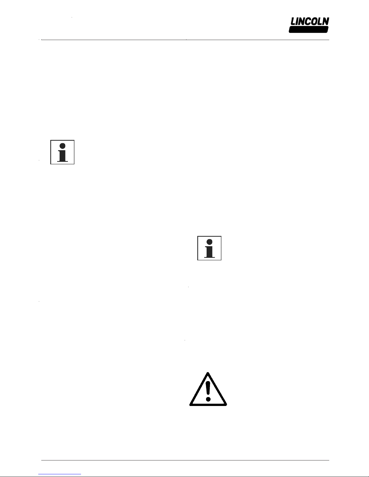
4239a99
Fig. 1 Single parts of the check va lve
Main- and secondary metering devices
Inlet tube fittings, straight and 90°
As inlet fitting use only tube fittings R1/8” thread.
Check valves
Install one complete check valve in each outlet bore that will
be used, see fig. 1.
Install one closure plug in e ach outlet borehole that will not be
used. Exception: outlet bore 1 & 2 on sizes6 to22. Check
valves must be installed in both bores.
1 coupling nut 3 valve body with seal and
clamp ring 2 ferrule
Tube Fittings, Push-in type
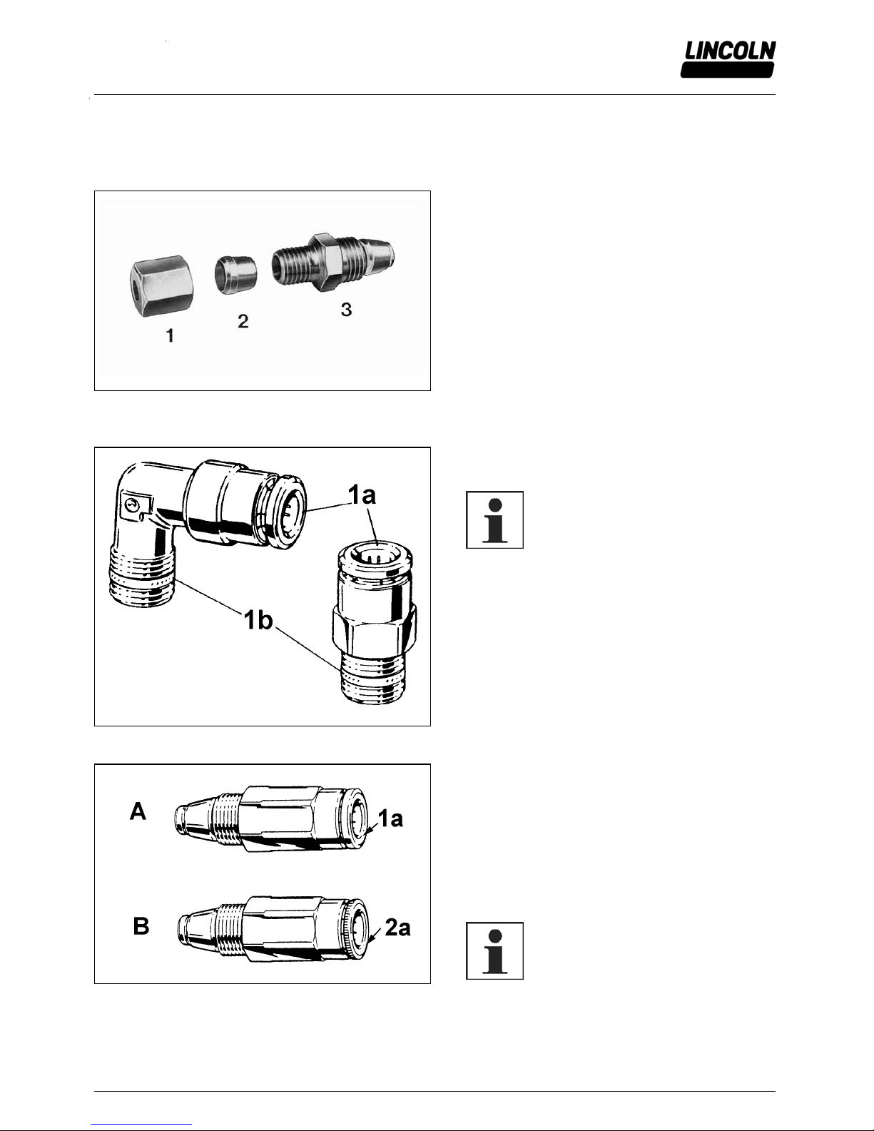
1008a98
Fig. 2 Inlet fittings
Metering devices
Inlet tube fittings, straight and 90 °
6001a02
IMPORTANT
For the inlet fitti ngs use only tube fittings
with reinforced collet 1a (fig. 2) and
sealing ring 1b at the thread.
1a Collet
1b Sealing ring
1009a98
Fig. 3 The different type s of check va lve
Check valves
A check valve must be mounted to the corresponding
metering device outlet of each feed line in order to be able
to precisely meter the predefined amount of lubricant.
Main metering device
Use check valves type A, Fig.3 with reinforced collet 1a
and smooth flange (Part no. 226-14091-4).
Secondary metering device
Use check valves type B, Fig. 3 with standard collet 2a
and knurled flange (Part no. 226-14091-2).
6001a02
NOTE
On construction machines or agricultural
machines use high-pressure plastic hoses.
In such cases the check valves of the
secondary metering devices must have a
reinforced collet and smooth flange.
A Check valve with reinforced collet
B Check valve with knurled collet
SKF Lubrication Systems Germany GmbH ● Heinrich Hertz-Str. 2-8 D-69190 Walldorf Tel. +49(0) 6227 33-0 ● Fax: +49 (0) 6227 33-259
Page 7
P 7 f 24
Subject to modifications
User Manual
Operating Instructions
2.2EN-20001-J11
Installation, continuation
Tube Fittings, Push-in Type, continuation
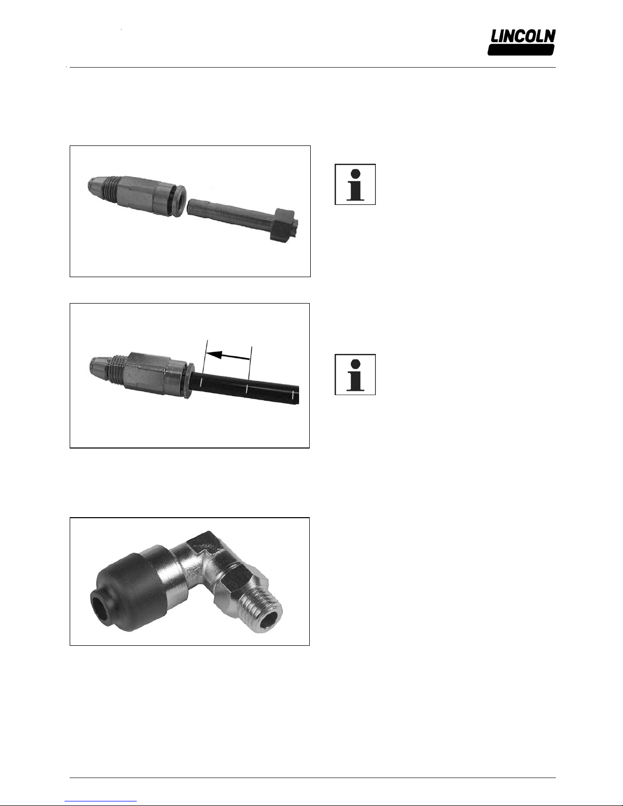
Connection of High-pressure Hose and Pressure Plastic Tube
4156a98
Fig. 4 Check valve with reinforced collet and hose stud
High-pressure range (main metering device)
60 01a0 2
IMPORTANT
Only main lines (NW 4.1 x 2.3 mm) with
threaded sleeve and hose stud may be
connected to the inlet fitting and the check
valves with reinforced collar.
4157a98
Fig. 5 Check valve with knurled collet and pressure plastic tube
Low-pressure range (secondary metering device)
Connect the pressure plastic tube (Ø6x1.5 mm) to the check
valve with standard collet (knurled collet) and to the inlet
fittings towards the lubrication point (knurled coll et).
60 01a0 2
NOTE
Special cases, such as applications for
construction machines or agricultural machines, require the use of check valves
and inlet fittings (towards the lube point)
with reinforced collet also for the lowpressure range. Refer to Parts Catalog.
The pressure plastic tubes are marked with white lines
(Fig. 5) as an installation aid.
Cut the pressure plastic tube off at one of the white lines
before it is mounted. Then insert the pressure plasti c tube
into the fitting up to the next white mark.
This will ensure a correct installation of the pressure plastic
tube in the tube fitting.
00002632
Fig. 6 Push in type fitting with protective cap
Protective cap for push-in type fittings
Push-in type fittings, check valv es and pressure relief v alv es
can be closed with a protective cap in order to av oid contamination.
Designation .......................................................... Part No.
Protective cap ................................................. 432-24313-1
SKF Lubrication Systems Germany GmbH ● Heinrich Hertz-Str. 2-8 D-69190 Walldorf Tel. +49(0) 6227 33-0 ● Fax: +49 (0) 6227 33-259
Page 8
P 8 f 2
Subject to modifications
User Manual
Operating Instructions
2.2EN-20001-J11
Installation, continuation
Pressure Plastic Tubes and High-pressure Hoses
Pressure plastic tubes Ø6 x 1.5 mm
Use the pressure plastic tubes only in the low-pressure
area, i.e. between secondary metering device and lubrication point.
6001a02
NOTE
Adhere to the pressures and bending radiuses mentioned in the chapter ”Technical
Data” when installing the parts and operating the device.
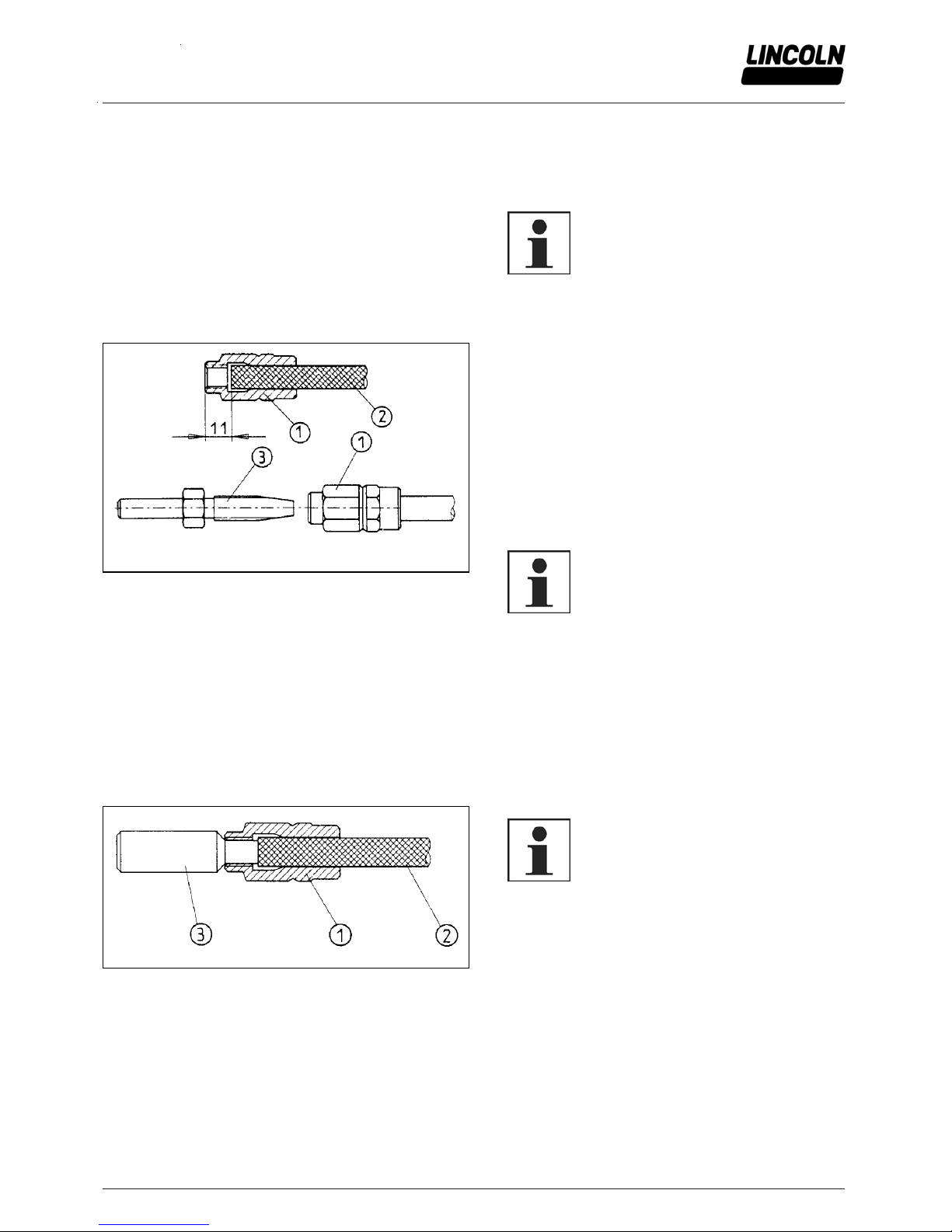
High-pressure hose NW 4.1 x 2.3 mm
1028a96
Fig. 7 Preassembly of threaded sleeves and hose studs on the
high pressure hose
1 Threaded slee ve
2 High pre ssure hose NW 4.1 x 2.3 mm
3 Hose stud
Use the high-pressure hose in the high-pressure area, i.e.
between the pump, main metering device and secondary
metering devices.
Adhere to the pressures and bending radiuses mentioned
in the chapter ”Technical Data” when installing the parts
and operating the device.
Installing the threaded sleeves and hose studs on the
high-pressure hose
Screw threaded sleeve, item 1 Fig. 7, counterclockwise
onto high-pressure plastic hose 2 until illustrated dimension of 11 mm is reached. Then screw hose stud 3 into
threaded sleeve 1.
6001a02
IMPORT ANT
Before screwing the parts 1, 2 (inside and
outside) and 3, rub them with oil.
NOTE
The outside diameter of the high-pressure
hose may show variations in dimension. In
such a case, press the threaded sleeve 1
at the end where it will be screwed onto
the high-pressure hose so that it becomes
oval in shape (1 to 2 mm). This will prevent
the high-pressure plastic hose from being
pushed out of the sleeve when the hose
stud is screwed.
1029a96
Fig. 8 Preassembly of threaded sleeve by means of adjusting
gauge
1 Threaded slee ve
2 High pre ssure hose NW 4.1 x 2.3 mm
3 Adjusting gauge 432 23077 1
6001a02
NOTE
When using the special adjusting gauge
432-23007-1 (see Parts Catalog) screw
threaded sleeve counterclockwise onto
high-pressure plastic hose until the gauge
inserted in the sleeve begins to rise.
SKF Lubrication Systems Germany GmbH ● Heinrich Hertz-Str. 2-8 D-69190 Walldorf Tel. +49(0) 6227 33-0 ● Fax: +49 (0) 6227 33-259
Page 9

P 9 f 24
Subject to modifications
User Manual
Operating Instructions
2.2EN-20001-J11
Progressive Metering Devices Model SSV, SSV-E and SSV M
10002709
Fig. 9 Metering device type SSV 8
Progressive plunger metering devices - general
The progressive meteri ng devi ces
- are piston-operated metering devices;
- automatically (progressively) dispense the lubricant fed
by the pump to the connected lubrication points;
- model SSV or SSV-E have a lubricant output of 0.2
ccm per outlet and piston stroke;
- model SSV M have a lubricant output of 0.07 ccm
per outlet and piston stroke;
- when one or more outlets are closed (see ”Combining
outlets”) they can dispense a double or multiple lubricant quantity;
- are available with 6 to 12 outlets or up to 22 outlets;
- offer the option of combining several lubricati on points
into one centralized lubrication point.
- meter the supplied lubricant into predetermined single
quantities.
- can be monitored visuall y (SSV, SSV-E and SSV M) or
electronically (SSV and SSV-E).
- in the SSV-E versi on include an emergency lubrication
fitting.
Any blockage in a lubrication circuit is indicated by grease
leaking from the respective pressure relief val ve.
10002710
Fig. 10 SSV 8 with p iston de tector
Features of a Progressive Metering Device
The term ”progressive” refers to the special features of
the lubricant distribution within the metering devices,
e.g.
- the successive movements of the i ndividual pistons
within the metering device due to the supplied lubricant
being under pressure;
- the pistons move in a predetermined order and the cycles are repeated constantly;
- each piston must have completed its movement fully
before the next piston can be moved, no matter whether
the lubricant is dispensed continuously or intermittently;
- the pistons operate interdependently of one another;
- no lubrication point, which is connected to the system,
is omitted.
Description
SKF Lubrication Systems Germany GmbH ● Heinrich Hertz-Str. 2-8 D-69190 Walldorf Tel. +49(0) 6227 33-0 ● Fax: +49 (0) 6227 33-259
Page 10

P 0 f 2
Subject to modifications
User Manual
Operating Instructions
2.2EN-20001-J11
Progressive Metering Devices Model SSV, SSV-E and SSV M, continuation
B-SSV-020a11
Fig. 11 Differe nces be tween SSV M a nd SSV/SSV E
E Emergency lubrication fitting
Different features of SSV, SSV-E and SSV M
The SSV-E progressive metering device consists of an
SSV progressive metering device and an emergency lubrication fitting E (fig. 11). Time for troubleshooting can be
reduced significantly by using e. g. a hand-lever gun in
combination with the emergency lubrication fitting.
The SSV, SSV-E and SSV M progressive metering devic-
es operate similarly. Apart from their outer dimensions
they also differ in the following data:
SSV and SSV-E
Lubricant output per outlet and stroke ......................... 0.2ccm
Maximum operating pressure ..................................... 350 bar
Minimum operating pressure ........................................ 20 bar
Maximum differential pressure between 2 outlets ....... 100 bar
Outlet connection for tube ................................ Ø 4 and 6 mm
SSV M
Lubricant output per outlet and stroke ....................... 0.07ccm
Maximum operating pressure ..................................... 200 bar
Minimum operating pressure ........................................ 20 bar
Maximum differential pressure between 2 outlets ......... 40 bar
Outlet connection for tube .......................................... Ø 4 mm
Applications
1205a95
Fig. 12 Central lubrication po int
Quicklub progressive metering devices offer the option of
combining several lubrication points on a machine to one
or more central lubrication points, as shown in Fig. 12,
which illustrates this basic feature.
4024b95
Fig. 13 Possible pump conne ctio ns
1 Hand opera ted p ump
2 Pneuma tica lly o pera ted pump
3 Electrically ope rate d pump
4 Lubrication fitting block
5 Hand operated filling pump
When they are used in connection with hand-operated
pumps, pneumatic or electric pumps the progressive metering devices are a simple and low-cost centrali zed lubrication system (see Fig. 13).
Mode of Operation
Description, continuation
SKF Lubrication Systems Germany GmbH ● Heinrich Hertz-Str. 2-8 D-69190 Walldorf Tel. +49(0) 6227 33-0 ● Fax: +49 (0) 6227 33-259
Page 11

P 11 f 24
Subject to modifications
User Manual
Operating Instructions
2.2EN-20001-J11
Applications, continuation
4025a95
Fig. 14 Multi line pump e xpande d by a progressive metering device
1207a95
Fig. 15 Two line system expanded by a pro gressiv e me tering
device
Progressive metering devices can be used in two-line or
single-line centralized lubrication systems in order to increase the number of outlets of multiline pumps or to subdivide the single metering devices and measuring valves
(Fig. 12 to 16) also as secondary metering devices in
large and small oil circulating systems.
1206a95
Fig. 16 Sing le line system e xpa nded by a p rogressive me terin g
device
Mode of Operation, continuation
SKF Lubrication Systems Germany GmbH ● Heinrich Hertz-Str. 2-8 D-69190 Walldorf Tel. +49(0) 6227 33-0 ● Fax: +49 (0) 6227 33-259
Page 12

P 2 f 2
Subject to modifications
User Manual
Operating Instructions
2.2EN-20001-J11
Lubricant distribution inside the metering device
The 5 following illustrations show the piston movements and
the depending lubricant distribution to the indiv idual outlets .
6001a02
NOTE
Illustrations fig. 17 to 21 show the sequence of delivery only of outlets 2, 7, 5, 3
and 1. Delivery of the residual outlets 8, 6
and 4 is derived from the logical pumping
until the com pl ete meter ing devi ce cycle
has finished. The functional principle of
SSV is identical with SSV M metering
devices.
When the lubricant supply is interrupted
- The pistons come to a halt;
- Lubricant is no longer dispensed to the lubrication point.
When the lubricant is supplied to the metering device again,
the cycle begins from the point where it had been interrupted.
2007a99
Fig. 17 Phase 1
Phase 1
The lubricant enters the metering device from above
(white arrow) and flows to the right-hand end of piston A.
Piston A (black arrow) moves to the left under the pres-
sure of the lubricant, causing the lubricant ahead of the
left-hand end of piston A to be dispensed to outlet 2
(dashed arrow).
Lubricant under pump pressure
Lubricant under deli ve ry pre ssure of the piston
Lubricant, without pre ssuress
2008a95
Fig. 18 Phase 2
Phase 2
Once piston A has reached its left-hand final position, the
junction channel to the right-hand end of piston B is
opened.
The lubricant, which arriv es from above (white arrow),
also moves piston B (black arrow) to the left and causes
the lubricant quantity ahead of the left-hand end of piston
B to be dispensed to outlet 7 (dashed arrow).
Lubricant under pump pressure
Lubricant under deli ve ry pre ssure of the piston
Lubricant, without pre ssuress
Mode of Operation, continuation
SKF Lubrication Systems Germany GmbH ● Heinrich Hertz-Str. 2-8 D-69190 Walldorf Tel. +49(0) 6227 33-0 ● Fax: +49 (0) 6227 33-259
Page 13

P 13 f 24
Subject to modifications
User Manual
Operating Instructions
2.2EN-20001-J11
Lubricant Distribution within the Metering Device, continuation
2009a95
Fig. 19 Phase 3
Phase 3
Once piston B has reached its left-hand final position, the
junction channel to the right-hand end of piston C is
opened.
The lubricant, which flows from above (white arrow)
moves piston C (black arrow) to the left, causing the lubricant quantity ahead of the left-hand end of piston C to be
dispensed to outle t 5 (dashed arrow ).
Lubricant under pump pre ssure
Lubricant under del ive ry pressure of the piston
Lubricant, pre ssurele ss
2010a95
Fig. 20 Phase 4
Phase 4
The channel of piston C to the right-hand end of piston D
is now open (black arrow).
The lubricant which is fe d from above (white arrow)
moves piston D to the left, causing the lubricant quantity
ahead of the left-hand end of piston D to be dispensed out
of the metering device via outlet 3 (dashed arrow).
Lubricant under pump pre ssure
Lubricant under del ive ry pressure of the piston
Lubricant, pre ssurele ss
2011a95
Fig. 21 Phase 5
Phase 5
In phase 4, piston D had opened the junction channel to
the left-hand end of piston A.
The lubricant flowing in (white arrow) moves piston A to
the right (black arrow), causing the lubricant quantity to be
dispensed to outlet 1(dashed arrow).
In the subsequent distribution sequence, pistons B - D are
moved from the left to the right one after the other.
A complete distribution sequence is finished and a new
cycle can begin.
Lubricant under pump pre ssure
Lubricant under del ive ry pressure of the piston
Lubricant, pre ssurele ss
Mode of Operation, continuation
SKF Lubrication Systems Germany GmbH ● Heinrich Hertz-Str. 2-8 D-69190 Walldorf Tel. +49(0) 6227 33-0 ● Fax: +49 (0) 6227 33-259
Page 14

P f 2
Subject to modifications
User Manual
Operating Instructions
2.2EN-20001-J11
Monitoring of the Operation
1064b95
Fig. 22 Example of a lubrica tion system
System-dependent monitoring
The main metering device B (fig. 22) and the secondary
metering devices are connected by a high-pressure
hose G. This feature automatically causes the linkage of
the progressive system connected downstream of the
pump.
If only one piston does not move in any metering device
or if the metering device can no longer dispense any lubricant via its outlets, this metering device will block itself.
If one of the secondary metering devices is blocked, the
main metering device is also blocked. The whole progressive system installed downstream of the pump stops operating.
The fundamental internal structure of the progressive
metering device guarantees the self-monitoring of the sequence within the metering device.
The linkage makes it possible to monitor the operation of
the whole system.
A
pressure relief valve E Pressure plastic tube
B Main mete ring dev ice SSV 6 F Se condary m ete ring
device SSV 12 C Secondary met ering dev ice SSV 8
D Secondary metering device SSV 6 G High pressure plastic hose
Fig. 23 Indicator pin instal led o n metering de vice
1011b96
Visual monitoring
The metering devices can be equipped with an indicator
pin which is connected to the piston and moves back and
forth during lubricant distribution.
If there is a blockage in the system, the indicator pin stops
moving.
6001a02
NOTE
It is also possible to electrically check the
movements of the indicator pin or any
blockage in the system by means of a
control switch (KS) or a proximity switch
(KN).
Components of the control pin tube fitting
Closure plug M 11x1x5 MS, assy. (pos. 1) ..........519-32123-1
Mode of Operation, continuation
SKF Lubrication Systems Germany GmbH ● Heinrich Hertz-Str. 2-8 D-69190 Walldorf Tel. +49(0) 6227 33-0 ● Fax: +49 (0) 6227 33-259
Page 15

P 15 f 24
Subject to modifications
User Manual
Operating Instructions
2.2EN-20001-J11
Monitoring of the Operation, continuation
00002634
Fig. 24 Pisto n dete ctor installed o n the me tering de vice
Electrical monitoring (microprocessor control)
A piston detector (initiator), which has been installed on
a metering device instead of a piston closure plug
(M 11 x 1), monitors the pump operating time and brings
it to a close after all the pistons of this metering device
have dispensed their lubricant quantity.
If there is a blockage in the system or if the pump reser-
voir is empty, the piston detector can no longer record the
piston movements. The switching off signal is not transmitted to the control unit. A fault signal occurs.
6001a02
NOTE
For the system monitoring it is recommended that one SSV-N metering device
with pre-assembled piston detector be
used per lubrication circuit. These special
metering devices must be ordered separately for each lubrication system. Refer to
the Parts Catal ogue.
The pre-assembled metering devices have the designa-
tion SSV ... - N (they are available for SSV 6, 8, 10
and 12). They must be installed in the system instead of a
normal metering device.
Applications:
6001a02
Metering device -
piston detector
Control unit / pump
SSV -NE
M08-23 / P203
MF01,02 / P223
MDF01,02,03 / P233
SSV -N
SSV -NP
PLC external
control unit
Mode of Operation, continuation
4092a97
Fig. 25 Pre ssure re lief valve
Pressure relief valve
The whole system can be monitored visual ly via the pres-
sure relief valve. If lubricant is leaking at the pressure relief valve during the distribution sequence, this indicates
that there is a blockage in the system.
6001a02
IMPORTANT
In the case of the progressive metering
devices models SSV6 to 22 and SSV6-E
to 22-E outlets 1 and/or 2 must never be
closed, otherwise the system will block
owing to the structure of the metering
device.
NOT E
Pressure relief valves to be ordered separately (see parts catalogue).
SKF Lubrication Systems Germany GmbH ● Heinrich Hertz-Str. 2-8 D-69190 Walldorf Tel. +49(0) 6227 33-0 ● Fax: +49 (0) 6227 33-259
Page 16

P 6 f 2
Subject to modifications
User Manual
Operating Instructions
2.2EN-20001-J11
Operation, continuation
Determining the Lubricant Output by Combining Outlets
Tube Fittings, Screw-Type
1012c96
Fig. 26 Install the outle t fitting s and closure plugs in accordance with the dosage
1 Inle t fitting 4 Closure plug (M 11 x 1), piston
(with chamfered)
7 Cutting ring
2 Delivery hole of the piston 5 Outlet fitting assembly 8 Coupling nut
3 Closure plug (M 10x1) with with hex.
socket head, installed
6 Valve body w ith clamp ing ring (bra ss) 9 Junctio n channel
The output quantities can be raised by closing outlet
boreholes.
6001a02
IMPORTANT
The structure of the progressive metering
devices would be blocked if outlet 1
and/or 2 is closed (with SSV 6-22).
Never close outlet 1 and/or 2 !
Install an outlet fitting assembly 5 (M 10x1) in each outlet
borehole which will be used. Refer to Fig. 26, 27, 28.
Never remove closure plug 4 (M 11x1 chamfered) on
the piston side or remove it only for installing a piston detector.
6001a02
NOTE
Never use closure plug 3 (M 10 x 1,
Fig. 20, 21) as a piston closure plug 4 (G
1/8) on older models of metering devices.
Clamping ring 6 closes the junction channels 9 to the
other outlet channels.
6001a02
IMPORTANT
Always use valve body 6 in conjunction
with clamping ring.
SKF Lubrication Systems Germany GmbH ● Heinrich Hertz-Str. 2-8 D-69190 Walldorf Tel. +49(0) 6227 33-0 ● Fax: +49 (0) 6227 33-259
Page 17

P 17 f 24
Subject to modifications
User Manual
Operating Instructions
2.2EN-20001-J11
Operation, continuation
Determining the Lubricant Output by Combining Outlets, continuation
Tube Fittings, Push-in-Type (main metering device)
B-SSV-030b11
Fig. 27 Install the push in type outlet fittings and the closure plugs in accordance with the dosage
1 Inlet fitting (optio na lly with protective
cap
1)
)
3 Closure plug (M 10x1) with with hex.
socket head, installed
5 Valve body a ssembly
(with reinforced collar)
2 Delivery borehole of the piston 4 Closure plug (M11x1),
piston, (chamfered)
6 Junctio n cha nnels
1)
on de ma nd
6001a02
NOTE
In the case of construction machines or
agricultural machi nes use hi gh-pressure
hoses for the lubricant feed lines. In this
case, secondary metering devices (see
fig. 26) must also be equipped with check
valves with reinforced collet (standard
flange, see fig. 3).
6001a02
NOTE
In the case of push-in type fittings the
clamping ring is always a firm component
of the valve body 5.
SKF Lubrication Systems Germany GmbH ● Heinrich Hertz-Str. 2-8 D-69190 Walldorf Tel. +49(0) 6227 33-0 ● Fax: +49 (0) 6227 33-259
Page 18

P 8 f 2
Subject to modifications
User Manual
Operating Instructions
2.2EN-20001-J11
Operation, continuation
Determining the Lubricant Output by Combining Outlets, continuation
Tube Fittings, Push-in Type (secondary metering devices)
B-SSV-030a11
Fig. 28 Install the push in type o utle ts fittings and clo sure plugs in accorda nce with the dosage
1 Inlet fitting 3 Closure plug (M 10x1) wit h hex . socket
head, in stalle d
5 Valve body assembly
(with knurled collar)
2 Delivery borehole of the piston 4 Closure plug (M11x1),
piston (cham fere d)
6 Junctio n channels
1014b96
Fig. 29 Single, double and trip le lubr icant output
... x Outlet quantity (1x: single, 2x: double, etc.)
1 .. 10 Outlet numbers
A Clam ping r ing (bra ss)
Single lubricant output
- The simple lubricant output is the lubricant quantity dispensed by a piston per stroke and per outlet borehole to
one lubrication point. It amounts to 0.2 cm³ on SSV
and 0.07 cm³ on SSV M.
Double or multiple lubrica nt output
If one or more lubrication points require a double or a
multiple lubricant amount, this can be performed by closing one or more outlets.
As shown in fig. 29, outlet borehole 10 has been closed.
The lubricant quantity supplied by this outlet flows out of
the metering device via outlet 8.
Total quantity at outlet 8:
- is the quantity of outlet 8
- plus the lubricant quantity of outlet 10.
If a triple quantity is needed (at outlet 1), close the outlet
borehole located above the discharge borehole. Refer to
outlets 3 and 5 on fig. 29.
SKF Lubrication Systems Germany GmbH ● Heinrich Hertz-Str. 2-8 D-69190 Walldorf Tel. +49(0) 6227 33-0 ● Fax: +49 (0) 6227 33-259
Page 19

P 19 f 24
Subject to modifications
User Manual
Operating Instructions
2.2EN-20001-J11
Fault: Blockage in the downstream progressive system
Cause: Correction:
Bearing, lines or metering device clogged. Find out which is the cause of the blockage and rectify it in
accordance with he following example:
In the case of the metering devices SSV 6 to 22 and
SSV6-E to 22-E the outlet boreholes 1 and/or 2 are closed.
The fault can be identified by:
a) grease leaking at the pressure relief valve;
b) the fact that the indicator pins installed on the metering
devices (if any) no longer move;
c) the fault signal of the signal lamp (if any) or LED display
A
llow pump to run (see ”To trigger an additional lubrication
cycle”).
Loosen all high press ure hose connections G one after the
other from the main metering device B (fig. 30) leading to
the secondary metering devices. If f. ex. grease or oil
emerges under pressure from outlet 1 of main metering
device B, the blockage will be found in the lubrication circuit of the secondary metering dev ice D.
6001a02
NOTE
If there is a blockage in the downstream
system, the main lines are under pressure.
In such a case, it is difficult to detach the
push-in type connecting parts of the main
line. Relieve the system by removing the
closure plug on the push-in type pressure
relief valve or, if any, by removing the fillin
g
nipple.
1064b95
Let the pump run.
Disconnect all lubricant feed lines E from secondary me-
tering device D one after the other. If f. ex. grease or oil
emerges under pressure from outlet 3 of metering device
D, the blockage will be found in the line of outlet 3 or in the
connected bea ring.
Pump the blocked bearing or line through by means of a
manual pump.
6001a02
NOTE
When checking the individual outlets, keep
each outlet loosened for quite a while
because per each motor revolution there is
only one piston stroke. A complete cycle of
all metering devices requires several
strokes.
Fig. 30 Example of a lubrica tion system
Check pressure relief valve A. Replace it, if necessary.
A
pressure relief va lve B Main m ete ring de v ice
C Se conda ry m ete ring device
SSV 8
D Secondary me te ring de vice
SSV 6
E Pressure p lastic tubes F Secondary me te ring de vice
SSV 12
G High pre ssure plastic hose
Troubleshooting
SKF Lubrication Systems Germany GmbH ● Heinrich Hertz-Str. 2-8 D-69190 Walldorf Tel. +49(0) 6227 33-0 ● Fax: +49 (0) 6227 33-259
Page 20

P 20 f 2
Subject to modifications
User Manual
Operating Instructions
2.2EN-20001-J11
Fault: Blockage in the downstream progressive system, continuation
Cause: Correction:
Metering device blocked Replace the metering device or clean it in accordance with
the following procedure:
Remove all tube fittings.
Unscrew the piston closure plugs.
If possible, try to eject the piston using a smooth drift
(Ø smaller than 6 mm).
6001a02
IMPORTANT
The pistons are precision-fitted into the
holes. Mark the pistons with regard to their
installation position and direction after they
have been removed. They must not be
exchanged.
Thoroughly clean the metering device bodies in fat-
dissolving washing agent, blow them through with compressed air.
Press free the slant ducts (Ø 1.5 mm) at the thread ends o
f
the piston holes using a pin.
Clean the metering devices again and blow them through.
Reassemble the metering devices.
Replace the copper washers.
Before the tube fittings are reassembled, the metering
devices should be pumped with oil several cycles by
means of a manual pump. Check that the pressure in the
metering device does not exceed 25 bar (362.8 psi).
If the pressure is higher, replace the metering device.
Fault: Differing lubricant amounts at the lubrication points
Cause: Correction:
Lubricant metering not correct Check the lubricant metering acc. to the lubrication chart
Respective valve body has been assembled without clamp-
ing ring
Remove the valve body and install a clamping ring.
Setting of the pause time or lubricating time incorrect Check the time setting. Refer to the corresponding setting
in the respective “Operating Instructions”.
Fault: Over- or underlubrication of the lubrication points
Cause: Correction:
Setting of the lubricating time or pause time incorrect Chec k the time setting at the printed circ uit boards. Re fer
to the corresponding setting in the respective “Operating
Instructions”.
Tab. 1 Trouble shooting, co ntinua tio n
Troubleshooting, continuation
SKF Lubrication Systems Germany GmbH ● Heinrich Hertz-Str. 2-8 D-69190 Walldorf Tel. +49(0) 6227 33-0 ● Fax: +49 (0) 6227 33-259
Page 21

P 21 f 24
Subject to modifications
User Manual
Operating Instructions
2.2EN-20001-J11
Technical Data
Metering Devices
Metering Device Model SSV and SSV-E
Lubricant output per outlet and per stroke ................. 0.2 ccm
Max. operating pressure ........................................... 350 bar
Min. operating pressure .............................................. 20 bar
Max.differential pressure
between two outlets .................................................. 100 bar
Outlet connection for tube ................................ Ø 4 and 6mm
Inlet connection ........................................................... G 1/8
Outlet connection ..................................................... M 10x1
Operating temperature ............................ – 40 °C to +200 °C
Metering Device Model SSV M
Lubricant output per outlet and per stroke ............... 0.07 ccm
Max. operating pressure ........................................... 200 bar
Min. operating pressure .............................................. 20 bar
Max.differential pressure
between two outlets .................................................... 40 bar
Outlet connection for tube ......................................... Ø 4mm
Inlet connection ........................................................... G 1/8
Outlet connection ....................................................... M 8x1
Operating temperature .............................. – 25 °C to +70 °C
Lines
High-pressure hose (∅ 4.1 x 2. 3 mm)
Min. bursting pressure
(in connection with hose clamp, screwed) ................. 600 bar
Min. bending radius ................................................... 35 mm
Min. temperature ...................................................... – 40 °C
Max. temperature ..................................................... + 60 °C
Pressure plastic hose (∅ 6 x 1.5 mm)
Min. bending radius ..................................................... 50 mm
Bursting pressure at 20° C ........................... approx. 210 bar
Min. temperature ...................................................... – 40 °C
Max. temperature ..................................................... + 60 °C
Screw-Type and Push-in Type Tube Fittings
High pressure range, p max. .................................... 350 bar
Inlet tube fittings of the metering devices
Outlet fittings, main metering device
Low-pressure range, p max. ..................................... 250 bar
Outlet fittings, secondary metering devices
Inlet fittings to the lubrication point
Tightening torques
Metering Device Model SSV and SSV-E
Closure plug (piston) in metering device ..................... 18 Nm
Closure plug (outlets) in metering device .................... 15 Nm
Inlet fitting in metering device
- screw-type ............................................................... 17 Nm
- plug-type .................................................................. 10 Nm
Outlet fitting in metering device
- screw-type ............................................................... 11 Nm
- plug-type .................................................................. 11 Nm
Compression nut onto outlet fitting, screw-type
- plastic tube ............................................................... 10 Nm
- steel tube ................................................................. 11 Nm
Control pin tube fitting in metering device .................... 18 Nm
Piston detecteur (N) in metering device ...................... 15 Nm
Proximity switch (KN) on metering device ................... 18 Nm
Install metering device
- dry ........................................................................... 10 Nm
- oiled ........................................................................ 7,5 Nm
Metering Device Model SSV M
Closure plug (piston) in metering device ....................... 6 Nm
Closure plug (outlets) in metering device ...................... 6 Nm
Inlet fitting in metering device
- screw-type ............................................................... 17 Nm
- plug-type .................................................................. 10 Nm
Outlet fitting in metering device
- screw-type ............................................................... 10 Nm
- plug-type .................................................................... 8 Nm
Compression nut onto outlet fitting, screw-type
- plastic tube ................................................................ 5 Nm
- steel tube ................................................................. 10 Nm
Control pin in metering device .................................... 10 Nm
Install metering device
- dry ............................................................................. 6 Nm
- oiled ........................................................................ 4,5 Nm
Metering device type SSV M flange
Install metering device .................................................. 6 Nm
SKF Lubrication Systems Germany GmbH ● Heinrich Hertz-Str. 2-8 D-69190 Walldorf Tel. +49(0) 6227 33-0 ● Fax: +49 (0) 6227 33-259
Page 22

P 22 f 2
Subject to modifications
User Manual
Operating Instructions
2.2EN-20001-J11
Dimensions
Metering Devices Model SSV6 to 22 & SSV6-E to 22-E
2012a95
Model SSV & SSV-E Dimensions A in
mm
6 60
8 75
10 90
12 105
14 120
16 135
18 150
20 165
22 180
Metering Devices Model SSV M 6 to SSV M 12
2012a99
Model SSV M Dimensions A in mm
6 48,5
8 60
10 71,5
12 83
Technical Data, continuation
SKF Lubrication Systems Germany GmbH ● Heinrich Hertz-Str. 2-8 D-69190 Walldorf Tel. +49(0) 6227 33-0 ● Fax: +49 (0) 6227 33-259
Page 23

P 23 f 24
Subject to modifications
User Manual
Operating Instructions
2.2EN-20001-J11
D GB F E I
EG- Einbauerklärung
EC Declaration of
incorporation
Déclaration CE
d'incorporation
Declaración CE
de incorporación
Dichiarazione CE di
incorporazione
Hiermit erklären wir, dass die
Bauart von
Herewith we declare that the
model of
Par la présente, nous déclarons que le produit ci-dessous
Por la presente, declaramos
que el modelo suministrado
Si dichiara che il prodotto da
noi fornito
Walldorf, Nov 30, 2009, ppa. Dr.-Ing. Z. Paluncic
Director Research & Development
Original Language
Metering Devices SSV / SSV-E / SSV M
in der von uns gelieferten
Ausführung zum Einbau in
eine Maschine bestimmt ist
und dass ihre Inbetriebnahme
solange untersagt ist, bis
festgestellt wurde, dass die
Maschine, in die das o. g.
Produkt eingebaut werden
soll, den Bestimmungen aller
einschlägigen grundlegenden
Sicherheits- und Gesundheitsanforderungen entspricht, einschließlich deren
zum Zeitpunkt der Erklärung
geltenden Änderungen. Der
Hersteller verpflichtet sich,
technische Dokumente (gem.
Anhang VII Teil B) bei begründeter Anfrage zum o. g.
Produkt einzelstaatlichen
Stellen in gedruckter Form zur
Verfügung zu stellen.
Angewendete harmonisierte
Normen, insbesondere:
in the supplied version is
intended to be incorporated
into machinery and must not
be put into service until the
machinery into which it is to
be incorporated has been
declared in conformity with
the provisions of the relevant
fundam en tal requirem ent s on
health and safety, including all
modifications of this directive
valid at the time of the declaration. The manufacturer
undertakes to make available
any technical documents in
printed version (following
Annex VII Part B) to subnational authorities in the case
of reasonable request regarding the above mentioned
product.
Applied harmonized standards in particular
:
dans la version dans laquelle
nous le livrons, est destiné à
être installé sur une machine
et que sa mise en service est
interdite tant qu’il n’aura pas
été constaté que la machine
sur laquelle le produit mentionné ci-dessus doit être installé est conforme aux réglementations régissant toutes
les exigences fondamentales
de sécurité et celles relatives à
la santé, y compris les amendements en vigueur au moment de la présente déclaration. Le fabricant s’engage,
en cas de demande justifiée, à
fournir sous forme écrite aux
organismes nationaux respectifs les documents techniques
(suivant Annexe VII, Partie B)
relatifs au produit ci-dessus.
Normes harmonisées, notamment :
en la versión suministrada es
destinada a ser incorporada
en una máquina y que su
puesta en servicio está
prohibida antes de que la
máquina en la que vaya a ser
incorporada haya sido
declarada conforme a las
disposiciones de los
requisitos pertinentes y
fundam en tales de salud y
seguridad en su redacción
vigente en el momento de
instalación. El fabricante se
obliga a hacer disponible
documentos técnicos (según
anexo VII parte B) en versión
imprimida a entes
uniestatales a petición
fundada referente al producto
arriba mencionado.
Normas armonizadas
utilizadas, particularmente:
nella versione da noi fornita è
destinato all’installazione in
una macchina e che la relativa messa in esercizio resta
vietata fino all’avvenuto
accertamento della conformità
della macchina nella quale il
suddetto prodotto deve
essere installato con tutti i
requisiti basilari prescritti in
termini di sicurezza e di
salute, incluse le relative
modifiche vigenti al momento
della dichiarazione. Il costruttore si impegna a mettere a
disposizione la documentazione tecnica (ai sensi
dell’Allegato VII partel B) in
forma scritta relativa al summenzionato prodotto dietro
richiesta motivata presso le
singole sedi nazionali.
Norme ar monizzat e applicat e
in particolare
:
Maschinenrichtlinie
2006/42/EG
Machinery Directive
2006/42/EC
Directive machines
2006/42/CE
Directiva de máquinas
2006/42/CE
Direttiva Macchine
2006/42/CE
DIN EN ISO 12100 – Teil 1 & 2 – Part 1 & 2 – Parties 1 & 2 – Parte 1 & 2 – Parte 1 e 2
Sicherheit von Maschinen Safety of machinery Sécurité de machines
Seguridad de máquinas
Sicurezza delle macchine
Grundbegriffe, allgemeine
Gestaltungsleitsätze
Basic terms, general design
guidelines
Notions fondamentales, direc-
tives générales d’élaboration
Términos básicos, axiomas
generales de diseño
Concetti basilari, principi
guida generali
DIN EN 809
Pumpen und Pumpengeräte
für Flüssigkeiten
Pumps an d pum p un its
for liquids
Pompes et groupes
de pompes pour liquides
Bombas y equipos de
bombas para líquidos
Pompe e dispositivi
di pompagg io per liq uidi
Allgemeine sicherungs-
technische Anforderungen
General safety requirements
Exigences en matière
de sécurité technique
Prescripciones generales
referente a la seguridad
Requisiti generali di sicurezza
tecnica
EMV-Richtlinien
2009/19/EG
EMC directives
2009/19/EC
Réglementations CEM
2009/19/CE
Directivas CEM
2009/19/CE
Direttive EMC
2009/19/CE
Kraftfahrzeug Automotive véhicules automobile vehículo autoveicolo
2004/108/EG 2004/108/EC 2004/108/CE 2004/108/CE 2004/108/CE
DIN EN 61000-
Fachgrundnormen:
- Störaussendun
g
Generic emission standards:
- Emitted interference
Normes fondamentales :
- Emission de parasites
Normas especiales fundam.:
- Emisión de interferencias
Norme specifiche fondam.:
- Emissione di inter
f
e
renze
Teil 6-4
a
)
Part 6-4
a
)
Partie 6-4
a
)
Parte 6-4
a
)
Parte 6-4
a
)
Teil 6-3 b) Part 6-3 b) Partie 6-3 b) Parte 6-3 b) Parte 6-3 b)
- Störfestigkeit - Noise immunity - Résistance aux brouillages - Resistencia a interferencias - Resistenza alle interferenze
Teil 6-2
a
)
Part 6-2
a
)
Partie 6-2
a
)
Parte 6-2
a
)
Parte 6-2
a
)
Teil 6-1 b) Part 6-1 b) Partie 6-1 b) Parte 6-1 b) Parte 6-1 b)
a
)
für Industriebereiche
a
)
for industrial environment
a
)
pour domaine industriel
a
)
para áreas industriales
a
)
per settore industriale
b
)
für Wohnbereich, Geschäfts und Gewerbebereiche sowie
Kleinbetriebe
b
)
for residential, commercial
and light industry
b)
pour domaines de l’habitation,
des magasins et de l’artisanat
ainsi que des petites
entreprises
b
)
para áreas res i de nci ales,
comerciales e industriales
tanto como pequeñas
empresas
b)
per il settore residenziale,
commerciale, industriale e
per le piccole impr ese
Dokumentations-
bevollmächtigter
Documentation agent
Responsable du Service
de documentation
Encargado/a de la
documentación
Responsabile della
documentazione
Wolfgang Studer • Heinrich-Hertz-Str. 2-8 • 69190 Walldorf
SKF Lubrication Systems Germany GmbH ● Heinrich Hertz-Str. 2-8 D-69190 Walldorf Tel. +49(0) 6227 33-0 ● Fax: +49 (0) 6227 33-259
Page 24

 Loading...