

Lincoln Series A, 85300 User Manual
It is the responsibility of the Owner/Operator to properly use
and maintain this equipment.
The instructions and Warnings contained in this manual
shall be read and understood by the Owner/Operator prior to
operating this equipment.
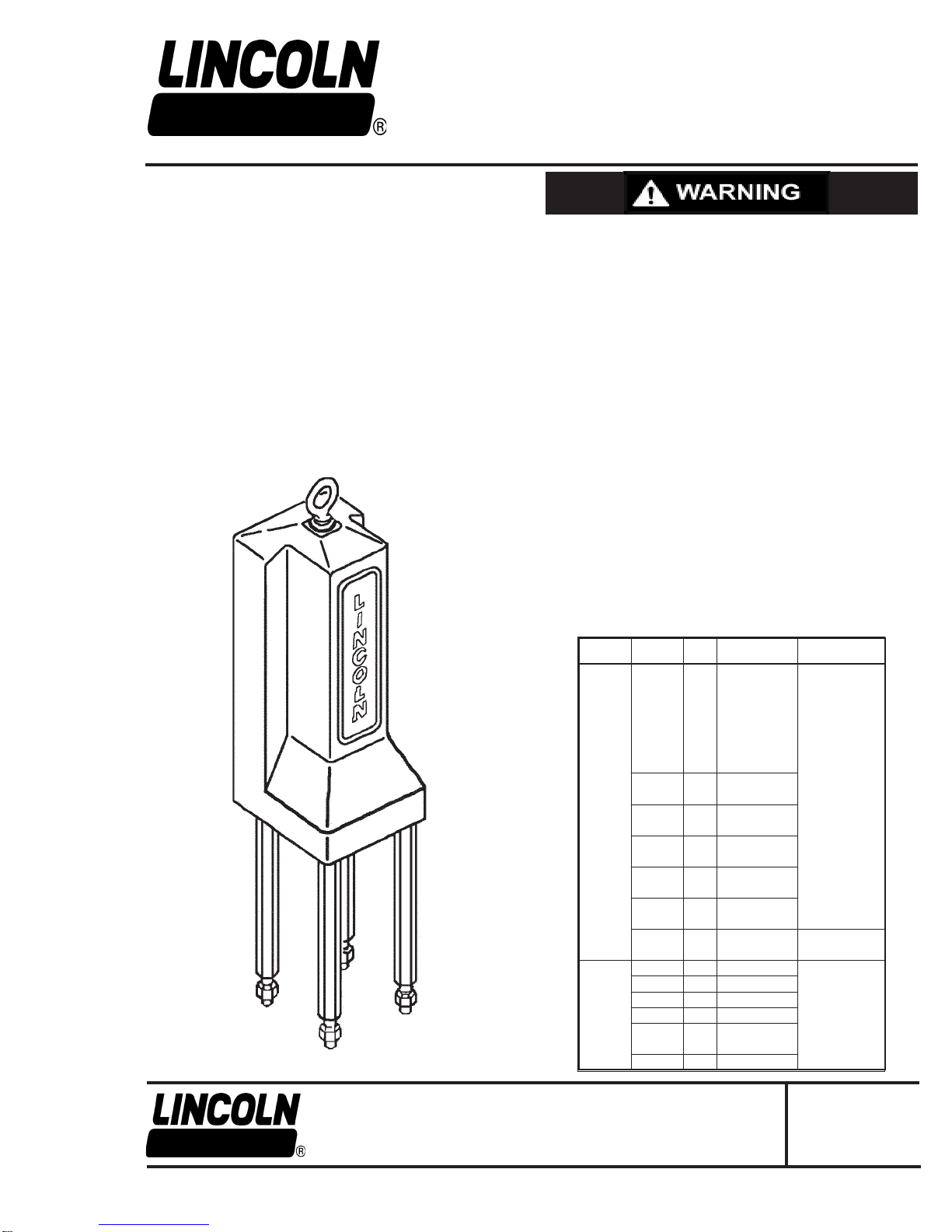
Model 85300
HYDRAULIC MOTOR
Series "A"
DO NOT exceed the stated maximum working pressure of
the hydraulic motor or of the lowest rated component in your
system.
DO NOT alter or modify any part of this equipment.
It is the responsibility of the Owner/Operator to maintain the
legibility of all Warning and Instruction labels.
The Owner/Operator shall retain this manual for future
reference to important Warnings, Operating and
Maintenance instructions.
DO NOT operate this equipment with combustible uids.
DO NOT attempt to repair or disassemble the equipment while
the system is pressurized.
TIGHTEN all uid connections securely before using this
equipment.
ALWAYS read and follow the uid manufacturer's
recommendations regarding uid compatibility, and the use of
protective clothing and equipment.
CHECK all equipment regularly and repair or replace worn or
damaged parts immediately.
IMPORTANT: Failure to heed these warnings including
misuse, over pressurizing, modifying parts, using incompatible
chemicals and uids, or using worn or damaged parts, may
result in equipment damage and/or serious personal injury, re,
explosion, or property damage.
Pump Type Pump Tube Ratio
POWER- 84981
Master 84982
III 84983
84984 1.5:1 2250 psi (155 bar)
84985
84986
84987
84976 2.5:1 3750 psi (258 bar) 1500 psi (103 bar)
84977
84978 4:01 6000 psi (412 bar)
84979
84991 3:01 4500 psi (310 bar)
84992
84993 4.5:1 6750 psi (466 bar)
84994
84995 5:1 7500 psi (517 bar)
84996
84997 7:1 7000 psi (483 bar) 1000 psi (69 bar)
84998
PILE 84900 0.8:1 1200 psi (83 bar)
DRIVER 84901 1:1 1500 psi (103 bar)
III 84902 1.5:1 2250 psi (155 bar)
84904 1:1 1500 psi (103 bar) 1500 psi (103 bar)
84921 0.4:1 600 psi (41 bar)
84922
84923 0.2:1 300 psi (21 bar)
Maximum Delivery
Pressure
Maximum Hydraulic
Inlet Pressure
JULY - 2011
To order call 1-800-548-1191 or visit www.partdeal.com - info@partdeal.com
One Lincoln Way
St. Louis, Missouri 63120-1578
(314) 679-4200
Copyright 2011
Printed in U.S.A.
Section
Page
-A50
- 87D
FORM 404258
Tools Required
1/8" Hex Key
3/16" Hex Key
1/4" Hex Key
Always check equipment for proper operation before each use,
making sure safety devices are in place and operating properly.
DO NOT alter or modify any part of the equipment as this may
cause a malfunction and result in serious bodily injury.
ATTACHING HYDRAULIC MOTOR TO PUMPTUBE
1. Tightly Attach Tie Rods (Item 38) to the Mounting Plate (Item 37).
(Use short threaded end of tie rods).
2. Mount hydraulic motor on top of pumptube outlet body and tightly
connect pumptube coupling nut to Piston Rod (Item 29).
3. Hand tighten tie rods to the pumptube with four Nuts (Item 39)
supplied with hydraulic motor.
4. Connect hydraulic supply and return lines and slowly cycle pump
several times, using only enough pressure to operate the pump
without stalling
NOTE: Air in the hydraulic motor may cause slow or erratic shifting during the rst few cycles after connecting the hydraulic lines.
5. Stop the pump on an "up" stroke and tighten the four nuts to
securely fasten the hydraulic motor to the pumptube.
9/16" Open End Wrench
3/4" Open End Wrench
1-1/4" Open End Wrench
1" Hex Socket Wrench
Procedure
1. Remove Eyebolt (Item 1) from top of hydraulic motor.
2. Remove Washer (Item 2), Cover (Item 3) and Spacer (Item 4).
3. Remove four Tie Rods (Item 38).
4. Remove four Screws (Item 5) and remove manifold subassembly
from cylinder subassembly.
5. Remove four Screws (Item 40) to separate Upper Manifold (Item
6) from Lower Manifold (Item 13).
6. Remove O-rings (items 8,9 &10) from Lower Manifold (Item 13).
7. Remove Cartridge Valve (Item 12) from Lower Manifold (Item 13).
8. Remove six O-ring Plugs (Items 7 &14) from Lower Manifold (Item
13).
9. Remove Cartridge valve (Item 11) from Upper Manifold (Item 6).
10. Remove nine O-ring Plugs (Items 7 & 14) from Upper Manifold
(Item 6).
11. Remove two O-rings (Items 19 & 20) from Cylinder Cap (Item 16)
and two O-rings (Items 20 & 32) from Cylinder Head (ltem 31).
12. Remove four Screws (Items 15) from Mounting Plate (Item 37).
To reduce the risk of serious bodily injury or property damage.
NEVER exceed the maximum uid working pressure of the lowest rated system component.
OPERATING PRECAUTIONS
• Use Lincoln replacement parts to assure compatible pressure
rating
• HEED ALL WARNINGS.
• Be sure material hoses and other components are able to withstand hydraulic pressures.
• Do not operate hydraulic motor continuously at speeds in excess
of 75 cycles per minute.
• Disconnect hydraulic line from hydraulic motor when system sits
idle for long periods of time.
• SERVICING. Before servicing hydraulic motor be sure to
carefully bleed pressure off of the system and disconnect the
hydraulic supply lines.
DISASSEMBLY
13. Remove Mounting Plate (Item 37).
14. Remove Cylinder Cap (Item16) from Cylinder Tube (Item 30).
15. Remove O-ring Plug (Item 14), Spring (Item 17) and Ball (Item
18) from Cylinder Cap (Item 16).
16. Remove O-ring (Item 21) from Cylinder Cap (item 16).
17. Remove Cylinder Tube (Item 30) from Cylinder Head (Item 31).
18. Remove Piston and Rod Assembly from Cylinder Head and
Bushing Assembly.
19. Remove Screw (Item 22) from Piston Rod (Item 29).
20. Remove Washers (Items 27 & 23) and Piston Cup (Item 24) from
Piston (Item 26)
21. Remove Piston Assembly (Items 25, 26 & 24) from Piston Rod
(Item 29)
22. Remove U-cups (Items 25 & 27) and Piston Cup (item 24) from
Piston (Item 26).
23. Remove O-ring (Item 28) and Washer (Item 23) from Piston Rod
(Item 29).
24. Remove Bushing (Item 34) from Cylinder Head (Item 31).
25. Remove O-ring (Item 21) from Cylinder Head (item 31).
26. Remove O-ring (Item 35), U-cup (Item 33) and U-cup/Wiper
(Item 36) from Bushing (Item 34).
27. To re-assemble hydraulic motor, reverse disassembly procedure
(Refer to illustration for torque specications).
Always disconnect hydraulic supply and relieve pressure before
beginning disassembly.
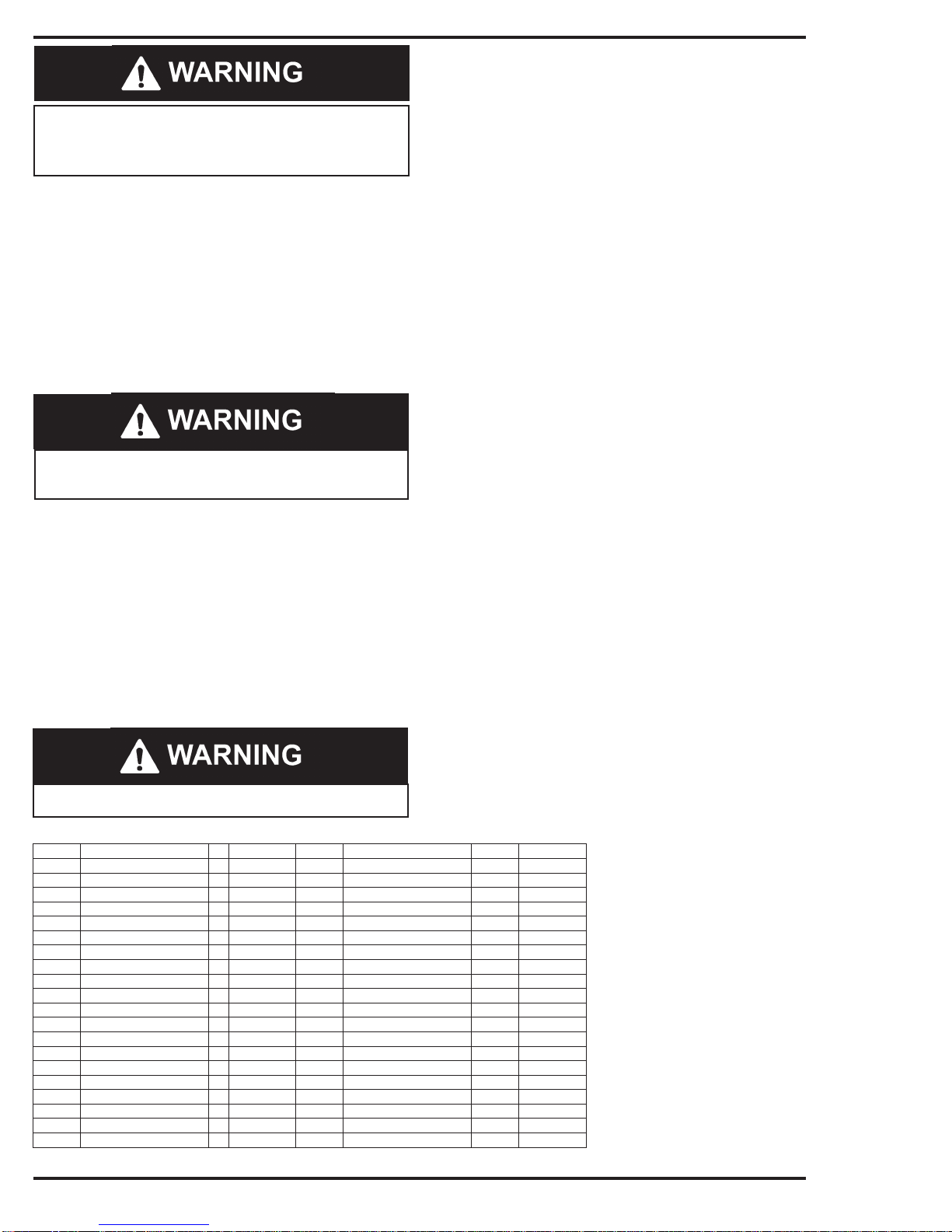
PARTS LIST
Item No. Description Qty. Part No. Item No. Description Qty. Part No.
1 Eyebolt 1 244741 21 O-ring (nitrile) 2 (Note #1)
2 Washer 1 48008 22 Screw 1 246005
3 Cover 1 244738 23 Washer 2 244770
4 Spacer 1 244742 24 Piston cup (polyurethane) 2 (Note #1)
5 Screw 4 244740 25 U-cup (polyurethane) 2 (Note #1)
6 Upper manifold 1 256148© 26 Piston 1 246003
7 O-ring plug (nitrile) 9 244752 27 Washer 1 48268
8 O-ring (nitrile) 1 (Note #2) 28 O-ring (nitrile) 1 (Note #1)
9 O-ring (nitrile) 1 (Note #2) 29 Piston rod 1 244816
10 O-ring (nitrite) 1 (Note #2) 30 Cylinder tube 1 244817
11 Cartridge valve (Note #3) 1 244812 31 Cylinder head 1 244758
12 Cartridge valve (Note #4) 1 244811 32 Onng (nitrile) 1 (Notes #1 & 2)
13 Lower manifold 1 244744 33 U-cup (polyurethane) 1 (Note #1)
14 O-ring plug (nitrile) 7 244753 34 Bushing 1 244818
15 Screw 4 244772 3S O-ring (nitrile) 1 (Note #1)
16 Cylinder cap 1 244754 36 U-cup/Wiper (polyurethane) 1 (Note #1)
17 Spring 1 (Note #1) 37 Mounting Plate I 244767
78 Ball 1 (Note #1) 38 Tie rod 4 241023
19 O-ing (nitrile) 1 (Notes # 1 & 2) 38 Nut 4 236203
20 O-ring (nitrile) 2 (Notes #1 & 2) 40 Screw 4 244751
NOTES: 1 only available as part of 244810 Soft Pans Kit.
2. Only available as pan d 24481 a Soft Pans kit.
Page 2 Form 404258
To order call 1-800-548-1191 or visit www.partdeal.com - info@partdeal.com
IMPORTANT: When attaching manifold subassembly to cylinder
sub assembly the eight Screws (Items 5 and 15) should be tightened together to maintain alignment of the "sealing surfaces
between the manifold and cylinder.
3. For cartridge valve seals only order 244814 Seal Kit.
4. For cartridge valve seals only order 244815 Seal Kit.
© Indicates change
 Loading...