

Lincoln RT-2AR Installation Manual
operator manual
Adjustable Range Toaster
This document includes:
• Safety Notices
• Specifications
• Installation Instructions
• Operating Instructions
• Cleaning Instructions
• Warranty Statement
Revision: C
P/N: 07008
Model RT-2AR
Lincoln Foodservice Products, LLC
1111 North Hadley Road
Fort Wayne, Indiana 46804
United States of America
Technical Support Hotline: (800) 678-9511
Telephone: (260) 459-8200
www.lincolnfp.com
BEFORE INSTALLATION
NOTE: Upon receipt of this unit, immediately unpack and inspect for possible concealed shipping d amage. If unit
is found to be damaged, save all packing materials and contact your delivery carrier within 5 days. Refer to
“Shipping Damage Instructions” enclosed for detailed instructions. Failure to follow these in structions will negate
Savory’s or your ability to file claims and receive compensation for shipping damage.
This manual contains important safety and installation-operation instructions. Require all operators to read this
manual before using the unit. Failure to follow the instructions contained in this manual may cause injury, damage
to the unit, and will void the warranty.
The RT-2AR should be placed in the most convenient location for ease of cleaning, maintenance, service and
general operation. Careful consideration should be given to avoid drafts, close proximity to grease or vaporproducing appliances or other high ambient heat equipment.
A minimum of ½” clearance is required for air circulation. This is assured by the rounded “acorn” nuts protruding
from the sides and rear of the unit. Overhead clearance from the top of the toaster should be as much as possible
and sufficient to allow heat dissipation.
INSTALLATION
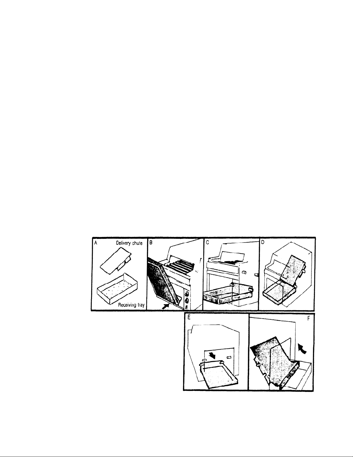
The toaster must be level for proper operation and comes equipped with adjustable legs for this purpose. The
receiving tray and delivery chute can now be installed (Figure A). Locate the four protruding pins inside the bottom
front opening of the toaster. The two lower pins lock the receiving tray into position. The two upper pins support
the delivery chute on one end. The other end of the chute rests on the lower pins so it lies at an angle from the
conveyor to the receiving tray. The receiving tray is installed first. Tilt the tray so that the back end slides along the
bottom of opening and passes under and behind the two lower pins (Figure B). With tray resting flatly on bottom of
opening, gently pull toward you until the back wall of tray is stopped by the pins (Figure C). The delivery chute is
now installed through the same opening. The notches in the sides must be with the open side down (Figure A).
Slide chute over the upper pins until they rest in notches then lower chute so opposite end rests on the lower pins
(Figure D).
Rear Delivery: Install toast receiving tray through
lower front opening and slide through until the one high
side wall rests against the two lower pins (Figure E).
The toast delivery chute is now installed through the
rear opening and brought up at an angle with the
curved end down. The notches closest to the upper
(flat) end on the chute rest over the upper pins. The
lower curved end of the chute rests in the receiving
tray (Figure F).
To convert to front delivery, remove receiving tray and
reinstall as shown in Figure A. Delivery chute is
inserted with curved end up and flat end resting in
receiving tray (Figure D).
RT-2AR Operator Manual
2
ELECTRICAL INSTALLATION
The RT-2AR toaster is available in 208V and 240V models. Voltage is specified on the data plate located on the
back panel of the toaster. The RT-2AR is factory supplied with a 3” power cord terminated in a NEMA approved
plug as specified for the particular voltage. For single phase operation, select the mating re ceptacle to match the
plug from the electrical specification chart shown.
The circuit on which the receptacle is installed must be of adequate wiring size and sufficient capacity to meet the
requirements indicated on the toaster data plate, and in conformance with the National Elect rical Code and local
electrical installation codes.
ELECTRICAL SPECIFICATIONS
Voltage Amps KW Plug Receptacle
208 20.3 4.2 6-30P 6-30R
240 17.6 4.2 6-30P 6-30R
Toaster is to be used with voltage specified
on data plate only. Warranty will be void if
toaster is used with any other than voltage
WARNING
specified on data plate.
OPERATION
!
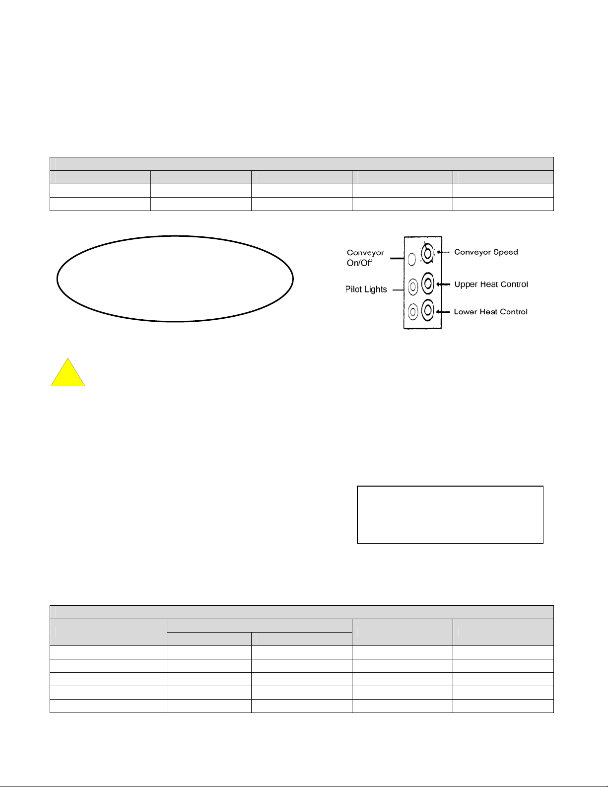
The RT-2AR is equipped with two heating zones, each consisting of two heating elements. These zones are
located above and below the conveyor belt and are controlled by the two heater control knobs located on t he front
of the unit.
The upper heating elements are regulated by the Upper Heat Control Knob and the lower heating elements are
regulated by the Lower Heat Control Knob. These controls can be used together for toasting both sides of a
product or independently for toasting one side of a product.
The conveyor motor is controlled by the ON/OFF switch. Conveyor
speed is regulated by the Conveyor Speed Control located above
the Upper and Lower Heat Controls.
INITIAL START-UP: After the toaster is installed, flip the ON/OFF
switch to the ON position and set the Conveyor Speed Control to
maximum speed setting (counter-clockwise until stopped).
Turn both Heat Control Knobs to #9. A 20-minute pre-heat time is required. After pre-heat period has elapsed, turn
heat control knobs to desired setting. Wait approximately 5 minutes for unit to cool down. The unit is now ready to
toast on two sides. (NOTE: See chart for guideline speed and heat settings.)
White Bread #9 #8 #6 #9
Whole Wheat Bread #9 #8 #5 #8
Rye Bread #5 #4 #4 #7
English Muffins #4 #3 #9 #9
Croissants #6 #4 #3 #7
WARNING – HOT SURFACES ARE PRESENT. PLEASE USE CAUTION WHILE OPERATING.
NOTE
To avoid damage to the conveyor
system, always have conveyor belt
running when heaters are working.
GUIDELINE AVERAGE SETTING CHART
PRODUCT
CONVEYOR SPEED
208V 240V
UPPER HEAT LOWER HEAT
RT-2AR Operator Manual
3
 Loading...