


PARTS & SERVICE MANUAL
for
RT-2AR
“ADJUSTABLE RANGE” TOASTER
The information found in this manual will prove very helpful. Although the instructions are easy to follow,
all repair procedures should be carried out by a qualified Savory Certified Service Representative.
THIS MANUAL SHOULD BE RETAINED FOR FUTURE USE
P/N: 07155 REV: 11.10.09

BEFORE INSTALLATION
The RT-2AR should be placed in the most convenient location for ease of cleaning, maintenance, service and
general operation. Careful consideration should be given to avoid drafts, close proximity to grease or vaporproducing appliances or other high ambient heat equipment. A minimum of ½” clearance i s required for air
circulation. This is assured by the rounded “acorn” nuts protruding from the sides and rear of the unit. Overhead
clearance from the top of the toaster should be as much as possible and sufficient to allow heat dissipation.
REPLACEMENT PROCEDURES
A – CASE REMOVAL
1. Remove reflector tray, toast pan and delivery
chute.
2. Remove the 2 screws along the front trim
panel and remove.
3. Remove left front panel.
4. Remove the 4 screws holding control panel to
unit and carefully pull panel towards you with
all wires intact. Slide control panel towards
center of unit.
5. With hands on each side of case, pull forward
to remove.
B – CASE REPLACEMENT
1. Slide case over unit making sure tabs on the
sides and top of case fit into grooves on back
of unit.
2. Carefully replace control panel.
3. Replace left front panel and front trim panel.
4. Replace reflector tray, toast pan and delivery
chute.
C – ON/OFF (MAIN POWER) SWITCH
1. With control panel removed (Section A),
remove the 2 slotted screws holding the
ON/OFF switch to the control panel.
2. Disconnect wires and remove switch.
3. Install new switch from rear of panel and
reconnect wires. (Refer to appropriate wiring
diagram)
D – CONVEYOR ON/OFF SWITCH
1. With the control panel removed (Section A),
disconnect wires to switch noting proper
orientation.
2. Remove bezel from front of panel and push
switch through back of panel.
3. Insert new switch from back of panel. NOTE:
Be sure terminals are in correct position.
4. Attach bezel on front of panel and tighten.
5. Re-attach wires to switch. (Refer to
appropriate wiring diagram.)
E – INFINITE CONTROL SWITCH
1. With control panel removed (Section A),
remove the infinite control knob to gain access
to the 2 slotted screws that hold the control to
the unit. Remove these 2 screws.
2. Disconnect wires from infinite switch terminals.
3. Install new switch from back of panel and
reattach wires. (Refer to appropriate wiring
diagram).
NOTE: The two (2) infinite controls on the RT-2AR
model serve as on/off switches to the heating
elements. The upper infinite knob controls the
upper elements and the lower infinite knob controls
the lower heating elements.
F – SPEED CONTROL / P.C. BOARD ASSEMBLY
NOTE: The speed control and P.C. board are wired
together and must be replaced as an assembly.
1. With control panel removed (Section A), loosen
set screws on speed control knob and remove.
2. Remove retaining nut that holds speed control
in place and remove from back of panel.
3. Disconnect motor lead and on/off lead from
P.C. board terminals.
4. Remove the 2 screws and nuts holding P.C.
board terminals.
5. Reverse this procedure to install new assembly.
(Refer to appropriate wiring diagram.)
P.C. BOARD ADJUSTMENT
The P.C. board is factory set and should not require
adjustment. If speed control range appears faulty,
the following procedure should be carried out:
1. Turn speed control knob clockwise until it stops.
2. Connect to power source and turn unit on.
3. Turn trimmer adjustment to right to start
conveyor motor running. Now turn trimmer
adjustment screw to the left to slow conveyor
motor. Continue turning screw until motor just
stops. Adjustment is now completed. All
further adjustments can be made by operating
at the speed control knob.
SPECIAL NOTICE: The RT-2AR is no longer built with the P.C. board installed. To wire or convert units with
the old style assembly, which included a resistor and/or P.C. board, do the following: The gear motor, whi ch
has 2 black wires, one is plugged into the white side of the terminal block, and the other one is spliced together
with the black wire off the Conveyor Speed Control POT. Then the blue wire off the Conveyor Speed Control
POT is attached to the On/Off Switch.
RT-2AR Service Manual
2
G – GEAR MOTOR
1. With outer case removed (Section A),
disconnect motor leads from on/off switch and
conveyor speed control and cut wire ties at
floor panel.
2. Remove the 2 retaining bolts from the
underside of the unit.
3. Remove the drive chain and lift out the motor.
4. Separate motor from motor mounting bracket
by removing the 4 slotted screws on the
bracket.
5. Using a 1/16” Allen wrench, remove the drive
sprocket from the motor shaft.
6. Attach new gear motor to motor mounting
bracket.
7. Install drive sprocket on motor shaft making
sure the Allen screw rests on the flat of the
shaft. Do not tighten set screw.
8. Install new motor with bracket attached. DO
NOT tighten retaining bolts.
9. Replace drive chain over sprockets.
10. Slide motor to right until drive chain is taut.
There should be approximately ¼” play in the
drive chain.
11. Check drive chain alignment. Tighten drive
sprocket set screws.
12. Reattach motor leads to on/off switch and
conveyor speed control. (Refer to appropriate
wiring diagram).
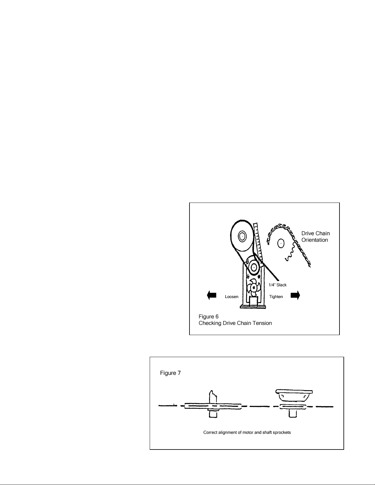
H – DRIVE CHAIN
1. With outer case removed (Section A), loosen
the 2 motor mounting bracket retaining bolts
on underside of unit, but DO NOT remove.
2. Slide motor to the left to loosen drive chain
tension.
3. Remove drive chain.
4. Install new chain over sprockets with open
looped side of chain facing out
5. Slide motor to right to tighten drive chain
tension. There should be approximately ¼”
plat in the drive chain.
6. Check for proper drive chain alignment.
(See figure 6 & 7)
7. Tighten motor mounting bracket retaining
bolts on underside of unit.
I – DRIVE (MOTOR) SPROCKET
NOTE: RT-2AR models use a 10T sprocket
1. With outer case removed (Section A) and drive
chain removed (Section H), loosen the set
screw on sprocket with a ¼” Allen wrench and
removed sprocket.
2. Install new sprocket on motor shaft making sure
Allen screw rests on the flat of the shaft.
3. Replace drive chain (Section H).
J – REAR (CONVEYOR) SHAFT SPROCKET
NOTE: RT-2AR models use a 40T sprocket.
1. With outer case removed (Section A) and drive
chain removed (Section H), loosen the 2 set
screws on sprocket with a 1/16” Allen wrench
and remove sprocket.
2. Install new sprocket on conveyor shaft aligning
the 2 set screws with the holes on the shaft.
3. Replace drive chain (Section H).
RT-2AR Service Manual
3
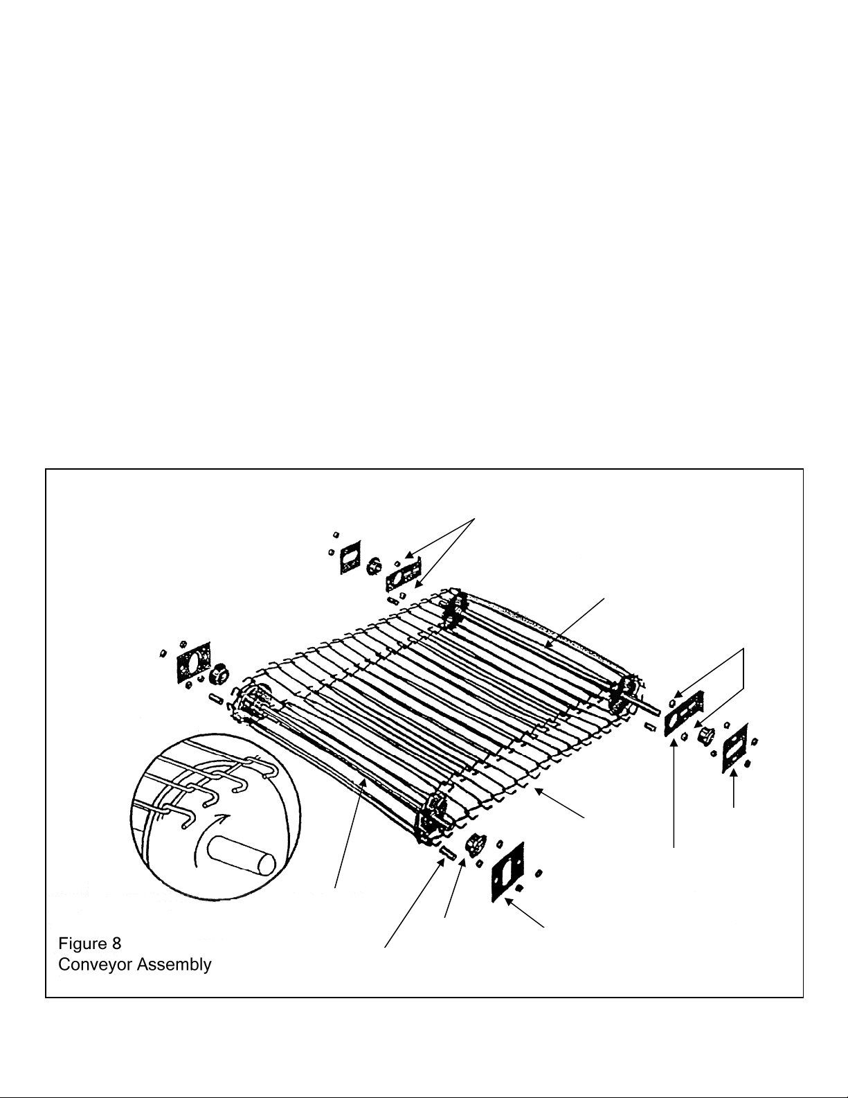
K – CONVEYOR CHAIN
Figure 8
5. With outer case removed (Section A), loosen
motor mounting bracket retaining bolts on
underside of unit, and slide motor to the left.
6. Loosen rear shaft adjusting bracket nuts and
bearing retaining bracket nuts on both sides of
unit.
7. Slide rear conveyor shaft forward to loosen
tension.
8. Separate the chain at any link and slide out
from front of unit.
9. Before installing new chain, check for proper
orientation (See Figure 8) and correct number
of links.
10. Starting at front of unit, slide chain under front
shaft and push towards rear of unit. Bring
chain up and over rear shaft assembly and
pull towards front. Connect links. CAUTION:
MAKE SURE CHAIN IS NOT INSTALLED AT
AN ANGLE.
1. Push back on rear shaft assembly until
excess slack is removed from chain. Holding
tension, tighten both the rear shaft adjusting
brackets and bearing retaining brackets on
both sides of unit.
2. Check for proper tension. There should be
approximately 3/8” to ¾” space between the
conveyor chain and the ledge on the inside of
the unit cavity.
3. Slide motor to the right to tighten drive chain
tension. There should be approximately ¼”
play in the drive chain.
4. Tighten motor mounting bracket retaining
bolts on underside of unit.
Spacer Nuts
Rear Shaft
Assembly
Wire Belt
Spacer Nuts
Bearing
Retainer
Tension Adjusting
Bracket
Front Shaft
Assembly
Front Spacer
RT-2AR Service Manual
4
Bearing
Bearing
Retainer