


2. CB6 (MEDLINE® CARELINE®)
The control box CB6 has been specially developed for use together with LA27/LA40 actuator in the care and rehab industry..
The control box is designed to be mounted on the actuator LA27/LA40 as with the CB9 and LA31 system..
The CB6 control box has a LED power ON indicator, detachable mains cable and strain relief for all cables..
The control box CB6 communicates with the LA27/LA40 actuator by means of the built-in end stop signal switches in the actuator.. Due to the signal switches the power to the motor will be cut off in the control box and not in the actuator..
Usage:
•Duty cycle: 2/18; 2 minutes continuous use followed by 18 minutes not in use
•CB6 is approved according to EN60601-1 / UL60601-1
•The CB6 can only be combined with LA27/LA40 and HB30 / HB70 / HL70 / HB80 and HL80..
Recommendations
•Be aware of the handset configuration (e..g.. CH1, 2, 3 should be CH1, 3, 4)..
•Same cables variants as for CB9 CARELINE and CB12..
Connecting the system:
• Do not connect the mains cable until all actuators have been connected to the control box..
• Start by connecting the handset to the control box.. The connection at the control box is marked with “HB”..
•Connect the different actuators to the different channels on the control box.. Each channel is marked with a number (e..g.. “1”, “2”, “3”.... . .)..
•Check that all plugs are well connected and firm pushed into the connection plug..
Due to the fact that LINAK control boxes are designed for a high IP degree, a firm force can be required..
•CONNECT the mains and turn on the power!
•Finally, connect the battery (BA18) with special T-cable or normal battery cable depending on the specified system..
•The actuators can now be operated by pushing a button on the handset.. Use only one button at a time..
If the control box is equipped with special software, an initialising process might be necessary.. This process is described in the software specification..
CB6 system diagram
Attention should be paid to the following:
•Control boxes must only be connected to the mains voltage specified on the label..
•The control box must be connected in such a way that the cables are not trapped, exposed to tension or sharp objects, when the application is moved in different directions..
Page 71 of 152
3. CB6 OBMe (MEDLINE® CARELINE®)
The CB6 OBMe is a powerful control box with switch mode power supply typically used for applications like hospital beds, couches/tables for treatment and examination and other medical applications.. The universal input voltage makes the control box adaptable to the world-wide market irrespective of the input voltage..
Approvals:
CB6 OBMe is approved according to UL60601-1 and EN60601-1..
Possible combinations.
CB6 OBMe is meant for use with: LA27 std.. motor (cable type ‘B’),
LA27 std.. motor (cable type “A” = encoded) with / without Hall LA31 std.. / fast motor with / without Hall,
LA34 std.. / small / fast motor with / without Hall (fast motor not max.. load), LA44 std.. / fast motor with / without Hall (fast motor not max.. load),
BL1 (only with +35% transformer type) with / without Hall, HB7x, HL7x, HB8x, FSE/FSL, FS2, MJB, DJB, ACO, ACC, ACK..
CB6 OBMe – with transformer has been approved for CLASS I operation incl.. CLASS I cables (without pigtail for earth)..
CB6 OBMe – with SMPS is not approved for CLASS I operation, basically because of the design of the housing.. However the PCB contains 2 x fuses (phase, neutral) as required for CLASS I operation..
If a mains cable with pig tail is applied CLASS I is obtained – however the CB label will indicate CLASS II! At the end of the day the OEM user applying for an application approval must clarify if such a solution is accepted by the used testhouse..
Battery Operation:
•If the battery voltage is at ‘low level’ a battery alarm beeps constantly by activating the HB/ACx.. Low level means that battery charging is necessary to maintain the best possible lifetime..
Low level battery limit corresponds to approx.. 19 V (+/- 5%)..
•If the battery voltage is at ‘critical level’ the battery alarm function shuts down all operation immediately..
If trying to operate the system anyway, the battery could become deeply drained or the actuator system could be damaged..
When at critical battery level there is a risk that the processor will incorrectly monitor end of stroke.. Crashing the actuator could be a result.. Critical level limit corresponds to approx.. 17..5 V (+/- 5%)..
•If battery back-up is applied it only commences battery charging when it is connected to the mains..
•A battery stored at 25° C has to be recharged every 6 - 7 months..
•Prior to first use of LINAK batteries, please make sure that they are charged for 24 hours in order to reach proper function and prolong the lifetime of the batteries..
•The longest lifetime is obtained when the battery is fully charged..
If Backlight supported HB is used:
•When CB6 OBMe is powered by mains voltage:
-If an HB button is activated the backlight illuminates fully.. When the HB button is released the light is dimmed again after approx.. 10 - 15 sec.. Backlight turns completely off after 2 min..
Exception: While charging the HB backlight will stay on dimmed until charging is finished..
•When CB6 OBMe is powered by battery:
-If a HB button is activated the backlight illuminates fully.. When the HB button is released the light is dimmed again after approx.. 10 - 15 sec.. Backlight turns completely off after 2 min..
1st Failure safe monitoring
Is made in two ways on the OBMe platform. It may be difficult to observe the LED status (hardware) if CB6 OBMe is placed under a bed, therefore it is now monitored by software as well.
•CB6 OBMe is equipped with a 1st Failure safe indication controlled by HW (power request).. At normal operation (no failure observed) the power LED turns yellow when a HB button is activated..
Page 72 of 152

If the LED has turned yellow AND the HB has NOT been activated, it indicates that a failure has occurred (1st Failure).
NOTE: Even though the LED illuminates yellow before the HB is activated it is possible to operate the CB6, however the 1st.. Failure is somehow still in the CB and must be removed to prevent a further failure causing a hazardous failure to happen..
•To meet the safety requirements the device must have a dual switch safety concept.. Further information about OpenBus™ safety concepts please contact your local LINAK..
•The safety function must be monitored and this monitoring is implemented in the SW.. In case of a failure (fatal error) any further operation of any channels are prevented.. At a fatal error the CB6 OBMe responds with the following information:
•Failure indication:
 all ACO LED’s are blinking
 The CB6 OBMe buzzer beeps shortly if a handset is activated
 The error can be reset by activating H0 and H1 OR H10 and H11 on a handset..
Compatibility – CB6 OBMe:
•CB6 OBMe supports both digital and analog encoded signals..
4.CB6P2 (MEDLINE® CARELINE®)
The CB6P2 platform is introduced to obtain a powerful and optimised solution to customers looking for existing analogue input systems.. It is based on OpenBus™ technology, but to meet existing analogue systems it has an analogue input similar to HB40 and therefore OpenBus™ accessories cannot be connected..
Combination Overview
CB6P2 is meant for use with:
LA27 std.. motor with Hall (cable type ‘A’) LA27 std.. motor (cable type ‘B’),
LA31 std.. / fast motor with / without Hall,
LA34 std.. / small / fast motor with / without Hall (fast motor not max.. load), LA40 std.. motor with / without Hall
LA44 std.. / fast motor with / without Hall (fast motor not max.. load),
BL1 (only with 270W transformer type) with / without Hall, HB7x, HL7x, HB8x, ACL/ACM/ACP (HB40-like)
Recommendations
Battery Operation:
•If the battery voltage is at ‘low level’, a battery alarm beeps constantly when the HB/ACx is activated..
(Low level means that battery charging is necessary to maintain the best possible life time.. Low level battery limit corresponds to approx.. 19 V (+/- 5%)..
•If the battery voltage is at ‘critical level’ the battery alarm function shuts down all operation immediately.. Critical level limit corresponds to approx.. 17..5 V (+/- 5%)..
•If battery back-up is applied it only commences battery charging when it is connected to the mains..
•A battery stored at 25° C has to be recharged every 6-7 months..
•Prior to first use of LINAK batteries, please make sure that they are charged for 24 hours in order to reach proper function and prolong the lifetime of the batteries..
•The longest lifetime is obtained when the battery is fully charged..
Page 73 of 152
5. CB6S (MEDLINE® CARELINE®)
CB6S is part of the LINAK OpenBus™ product range - that provides more flexible solutions no matter which actuator concept is preferred..
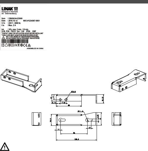
Mounting of CB6S – article no.. 9271233
Apart from LA27 and LA40, it is not possible to mount CB6S onto LINAK actuators.. In such case you need a CB6 mounting bracket which can be welded or likewise to the application..
This bracket is shown below:
Precautions:
Thermal protection:
OBF only
The CB is equipped with a thermal protection to avoid thermal overload of the FET transistors used to control the acuators..
When triggering the thermal protection all movement of the actuators will stop and the buzzer will sound for 5 seconds constantly.. The 5 second alarm will be reinitiated each time the handset/ACP or similar is activated until the CB is cooled down enough to allow a movement again
The thermal monitoring system monitors a temperature rise and not an absolute temperature.. The monitoring system has been designed to operate up to an ambient temperature of 40 degrees.. If the CB is exposed to a temperature higher than 40 degrees for several hours while powered it will adapt to this temperature.. In this case there is a risk of damaging the FET transistors without triggering the thermal protection..
At first power up, after programming a new SW into the CB, the ‘temperature reference value’, used by the thermal monitoring system, will be automatically initialized.. If this is done in a cold area the temperature reference value will be set accordingly and a too early temperature warning could occur (warning signal is temperature hoot = constant beep)!
After the first power up, the temperature reference value will adapt over time to the surrounding temperature and the adaptation routine happens every 5 hours (provided the CB is unused and connected to mains).. The 5 hour counter (used by the temperature adaptation routine) will be reinitiated every time a handset/control panel is activated..
We therefore recommend that the CB is resting for min.. 5 hours to adapt temperature wise to a ‘normal operating’ temperature, i..e.. in the environment for intended use..
Page 74 of 152

Recommendations
NOTE - HOT PLUGGING
Removing or adding any OpenBus cables is not allowed when the CB is powered by mains supply!
If needed anyway, follow the below procedure:
1..Remove mains and wait 5 sec..
2..Mount or dismount the required cables
If this procedure is NOT followed, it may result in a damaged OpenBus driver circuit..
The risk of a damaged circuit increases if the accessory has a high start current (in rush current)..
OBF - hot-plugging protected from January 2016..
Precautions:
BATTERY OPERATION:
OBL and OBF:
•IIf the battery voltage is at ‘low level’ a battery alarm beeps constantly (Low level means that battery charging is necessary to maintain the best possible lifetime.. Low level battery limit corresponds to approx.. 19 V (+/- 5%)..
•If the battery voltage is at ‘critical level’ the battery alarm function shuts down all operation immediately..
(If trying to operate the system anyway, the battery could become deeply drained or the actuator system could be damaged.. When at critical battery level there is a risk that the processor will incorrectly monitor end of stroke.. Crashing the actuator could be a result.. Critical level limit corresponds to approx.. 17,5 V (+/- 5%)..
•The CB6S with battery back-up only commences battery charging when it is connected to the mains..
•A battery stored at 25° C has to be recharged every 6-7 months..
•Prior to first use of LINAK batteries, please make sure that they are charged 24 for hours in order to reach proper function and prolong the lifetime of the batteries..
•The longest lifetime is obtained when the battery is fully charged..
IF BACKLIGHT SUPPORTED HB IS USED:
•When CB6S is powered by mains voltage:
-At no operation of the HB the backlight in the HB is dimmed..
-If a HB button is activated the backlight illuminates fully..
When the HB button is released the light is dimmed again after approx.. 10-15 sec..
•When CB6S is powered by battery:
-At no operation of the HB there is no backlight in the HB..
-If a HB button is activated the backlight illuminates fully.. When the HB button is released the backlight turns off..
OBF
• More information about “OpenBus SW guidance”, please contact your local LINAK..
Mounting of LA27/LA40 on OBF:
• It is not recommended to mount LA27/LA40 on OBF because of the big toroidal transformer used..
Page 75 of 152
6. CB7 (HOMELINE®)
Compared to other LINAK control boxes the CB7 is very small and compact in design..
The CB7 is designed to slide onto an LA31 actuator for easy fitting e..g.. in a recliner application where “mounting” space is limited..
The control box function is divided in two parts.. The actual control box CB7, which slides onto the LA31 actuator and a separate external power supply transformer box TR6 or TR7, which can be wall mounted or placed on the floor moulding next to the mains..
The control box is only fitted with low voltage electronic components and the connection between the CB7 and transformer is via a 24 V power cable..
7. CB8A (MEDLINE® CARELINE® TECHLINE®)
|
|
The CB8A is a battery powered control box operating up to 3 actuators |
|
|
individually.. One of these channels can be used either as an external |
|
|
emergency stop device or for battery charging.. |
|
|
Simple design and high quality construction make the CB8A an ideal |
|
|
control box choice for mains-free operation of beds, chairs, tables and |
|
|
many other mobile applications.. |
Usage: |
|
|
• |
Duty cycle: |
Max.. 10% or 2 min.. in use followed by 18 min.. not in use |
• |
Ambient temperatures: |
+ 5o to +4 0o C |
• |
Approvals: |
IEC60601-1:2005 3rd edition approved ANSI/AAMI, ES60601-1:2005 3rd edition approved.. |
Warning
In order to avoid injury, the emergency stop should be activated in (all) transport situations..
Recommendations
•Note: max.. accumulated power consumption is 10 Amp..
•The measurement is individual for each channel, but if the total current consumption reaches 10 Amp, the CB cuts off the current.. The CB and the actuator are therefore protected via a common measurement..
•External Charger CH01 has to be ordered separately.. By use of charger CH01 it is possible to activate the actuators when charging.. However, this is not recommended as it can damage the control box or the charger CH01..
•Battery kit BA0801 has to be ordered separately for versions M, G, H, Q, R (2 channel) and version M (3 channel)..
•An external emergency stop device (NC) or short-circuiting connection must be mounted from channel 3 of CB800XXXXN-X0 before connection to allow proper function and battery charging..
•When using the CB8A with emergency stop button, the stop button must be released before charging batteries..
• Acoustic alarm sounds when batteries are low and recharging should be started.. The alarm level corresponds to approx.. 17-18 VDC..
•If the CB800XXXXN-X0 option is chosen, An external emergency stop device (NC) or short-circuiting connection must be mounted in channel 3, before connection to allow proper function and battery charging..
•If the option N for CH3 is chosen, the external emergency stop has to be placed on channel 3, otherwise the CB8A will not work..
Important: Individual current cut-off:
The current to each actuator is monitored and when this reaches a specified value, the current to that actuator is cut-off..
As the actuators do not have the same current consumption the cut-off values must also be different.. Therefore it must be specified which actuator is to be connected to which channel:
CURRENT CUT-OFF (A)
2 A (2..35 +/- 0..35 Amp)
3 A (3..00 +/- 0..35 Amp) |
Values in brackets |
|
|
show tolerances.. |
|
4 A (4..00 +/- 0..50 Amp) |
||
|
||
|
|
|
5 A (5..35 +/- 0..50 Amp) |
|
|
|
|
|
6 A (5..90 +/- 0..70 Amp) |
|
Page 76 of 152

8. CB8-T (MEDLINE® CARELINE® TECHLINE®)
The CB8-T is developed for use with LINAK A/S’ actuators and handsets..
The control box can operate up to 2 actuators individually..
The simple compact design combined with high quality makes the control box ideal for use with beds, chairs, tables and many other applications..
Important: Individual current cut-off:
The current to each actuator is monitored and when this reaches a specified value, the current to that actuator is cut-off..
As the actuators do not have the same current consumption the cut-off values must also be different.. Therefore it must be specified which actuator is to be connected to which channel:
CURRENT CUT-OFF (A) |
|
|
2 A (2..35 +/- 0..35 Amp..) |
Values in brackets |
|
show tolerances.. |
||
|
||
3 A (3..00 +/- 0..35 Amp..) |
||
|
||
|
|
|
4 A (4..00 +/- 0..50 Amp..) |
|
|
|
|
|
5 A (5..35 +/- 0..50 Amp..) |
|
|
|
|
|
6 A (5..90 +/- 0..70 Amp..) |
|
|
|
|
9. CB9 (HOMELINE®)
The CB9 has been developed for Home use.. The CB9 and the LA31 can be fully integrated, which saves mounting and wiring or be installed separately..
The HOMELINE CB9 series is available as either analogue (Ax) or μ-processor based (Px) types..
10. CB9 (MEDLINE® CARELINE®)
The CARELINE® CB9 has been developed for use together with LA31/LA31R, LA34/LA34R* in the Care & Rehab industry.. CB9 and LA31 can be fully integrated which saves mounting and wiring or be installed separately..
Exchangeable mains cables, Electronic Overload Protection (EOP), EAS, earth connection (Class 1) and exchangeable mains fuse makes CB9 a good choice for the simple hospital and care beds..
Usage:
•Duty cycle: Max.. 10% or 2 min.. continuous use followed by 18 min.. not in use
•Ambient temperature: + 5° to + 40°C
•Compatible with up to 4 actuators, type LA31/LA31R and LA34/LA34R, via 4-pole DIN sockets
•Compatible with BA18
•Medically approved according to EN 60601-1/UL 60601-1
Recommendations
LA34 fast motor is not compatible with any standard versions of CB9, due to high current consumption.. For use of LA34 standard motor and small motor always use a CB9 with EAS..
Additionally, actuators with reed switch may not be connected to AC, AJ, AK, AF, AL or AM types because of a conflict between the CB-signal wires and the reed wires !
.... .to be continued
Page 77 of 152
CB9 is equipped with a green LED for indication of mains power connected..
•When th CB9 is connected to mains, the LED is green..
•Connected only to battery, the LED is off..
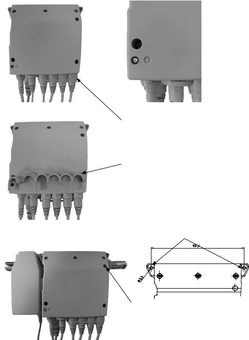
CB9 mounted on actuator, LA31..
Screw used for mounting
The cables are locked in position with a locking mechanism..
The locking mechanism is shownhere (not in position)
CB9 for mounting on application..
Shows the two holes used for mounting
CB9 can be mounted and fixed together with LA31 with one screw..
Page 78 of 152

11. CB9 CARELINE Basic (MEDLINE® CARELINE®)
The CARELINE® Basic CB9 has been developed for use together with LA31 and LA34 in the Care & Rehab industry..CB9 and LA31 can be fully integrated thus saving mounting and wiring or they can be installed separately.. Exchangeable mains cables, Electronic Overload Protection (EOP) and earth connection (Class 1) mains fuse makes CB9 a good choice for simple hospital and care beds.. The CARELINE® Basic CB9 series is only available as an analogue (Ax) type..
Microprocessor:
With LINAK software packages the Px types are aimed at applications where parallel drive and/or memory functions are required.. Please consult the ordering example for a detailed description of the article number..
Internal battery charger:
Compatible with BA18..
If anything other than a LINAK® charger is used, it must conform to the following specifications:
Charging voltage: 27..6 VDC ± 2% Charging current: < 300 mA..
EOP:
AC and AF: Means common measurement on CH1, CH2, CH3 and CH4.. If the total current exceeds 5A all channels will be cut off..
AJ and AL: Means a common current measurement on CH1+2.. The current will be cut off when the total current on both channels reaches approx.. 3..4A and 7A on CH3+4..
Note: CH1+2 = LA31 connection and CH3+4 = LA31/LA34 connection..
AK and AM: Means common measurement on CH1, CH2, CH3 and CH4.. If the total current exceeds 7A all channels will be cut off..
AS: Means an individual current measurement on CH1, CH2, CH3 and CH4.. The current will be cut off only when the current on one channel reaches approx.. 4A..
Max.. current available from the CB9 transformer is approx.. 7A..
Px: Means Electronic Overload Protection via a pulse measurement..
Usage: |
|
• Duty cycle: |
Max.. 10% or 2 min.. continuous use followed by 18 min.. not in use |
•Ambient temperature: + 5° to + 40°C
•Compatible with up to 4 actuators, type LA31/LA31R and LA34/LA34R, via 4-pole DIN sockets
•Compatible with BA18
•Medically approved according to EN 60601-1/UL 60601-1 3th Edition
Recommendations
The LA34 fast motor is not compatible with any standard versions of the CB9, due to high current consumption.. For use of the LA34 standard motor and small motor always use a CB9 with EAS..
Additionally, actuators with reed switch may not be connected to AC, AJ, AK, AF, AL or AM types because of a conflict between the CBsignal wires and the reed wires !
12. CB12 (MEDLINE® CARELINE®)
The CB12 product range features two standard versions, which are ideal for a vast number of medical and industrial applications..
In general the CB12 is a transformer operated control unit, which can control up to 4 actuators.. The control box feature a range of built-in safety devices, increased current cut-off, EAS (Electronic Arc Suppression), and other options such as battery backup, earth outlet, wet alarm etc..
CB12 with battery backup
The CB12 with battery backup has an acoustic alarm, which sounds when the batteries are low, approx.. 17 - 18V.. To charge the batteries on a CB12 with internal batteries, just connect the CB12 to mains.. With external batteries, connect the external batteries to an external charger..
External battery charger
If anything other than a LINAK® charger is used, it must conform to the following specifications: Charging voltage: 27..6 VDC ± 2%
Charging current: < 300 mA..
Warning
In order to avoid injury, a system with control(s) or accessories, a CB12 with battery backup and actuators assembled, must always be disassembled in transport and service situations..
Page 79 of 152

13. CB14 (MEDLINE® CARELINE® TECHLINE®)
The CB14 with microprocessor is developed for systems with a need to run up to five actuators or two actuators / lifting columns in parallel and / or with memory function..
The effective toroidal transformer and the many features such as battery backup, earth outlet, wet alarm makes the control box suitable for a variety of applications..
CB14 with battery backup
The CB14 with battery backup has an acoustic alarm, which sounds when the batteries are low, approx.. 17-18V.. To charge the batteries on a CB14 with internal batteries, just connect the CB14 to mains.. With external batteries, connect the external batteries to an external charger..
Memory position on CB14
When storing the memory position on CB14 the actuators must be run to the wanted position and the “store” button (S) must be pushed.. Hereafter, the selected memory button (1, 2, or 3) must be activated within 2 seconds..
Microprocessor
All control boxes with a microprocessor must be initialized before start-up.. A description of the initialisation procedure can be obtained from your LINAK dealer.. If an actuator is replaced, the microprocessor always has to be initialised before use (actuators with reed/hall)..
If re-programmed, please ensure that the correct software is used..
External battery charger
If anything other than a LINAK® charger is used, it must conform to the following specifications: Charging voltage: 27..6 VDC ± 2% Charging current: < 300 mA..
Warning
In order to avoid injury, a system with control(s) or accessories, a CB14 with battery backup and actuators assembled, must always be disassembled in transport and service situations..
14. CB16 (MEDLINE® CARELINE®)
CB16 is part of the LINAK® OpenBus™ product range.. It is a powerful control box with either traditional transformer solution or Switch Mode Power Supply..The universal Switch Mode Power Supply makes the control box adaptable to the worldwide market irrespective of the input voltage..
Usage: |
|
|
• |
Approvals: |
CB16OBF/OBL is approved according to IEC60601-1:2005 3rd ed.., ANSI / AAMI ES60601-1:2005, 3rd edition, |
|
|
CAN / CSA-22..2 No 60601-1:2008.. |
• |
Compatibility: |
LA27 (no feedback/encoded feedback), LA31, LA34, LA43, LA44, BL1, and BL4 |
• |
Duty cycle: |
10%, 2 minutes continuous use followed by 18 minutes not in use |
•Usage temperature: 5ºC to 40ºC
•Storage temperature: - 10ºC to 50ºC
Recommendations
NOTE - HOT PLUGGING
Removing or adding any OpenBus cables are not allowed when the CB is powered by mains supply!
If needed anyway follow the below procedure:
1..Remove mains and wait 5 sec..
2..Mount or dismount the required cables
If this procedure is NOT followed it may result in a damaged OpenBus driver circuit..
The risk of a damaged circuit increases if the accessory has a high start current (in rush current)..
NOTE - Use of internal mains signal in software or on OpenBus
Please note when using the internal mains signal on control boxes with SMPS that the mains signal may take up to 6 seconds before disappearing after mains has been removed..
Battery operation: |
|
BATTERY LEVELS |
|
Battery High: > 20 V |
- normal |
Battery Medium: 18-20 V |
- alarm |
Battery Low: < 18 V |
- critical |
Page 80 of 152
•If the battery voltage is at ‘Medium level’ a battery alarm beeps as long as a key is activated.. (Medium level means that battery charging is necessary to maintain the best possible lifetime)..
•If the battery voltage is at ‘Low level’, the battery alarm function shuts down all movement immediately.. The OpenBus is still active for approx.. 15 seconds.. (If trying to operate the system anyway, the battery could get deep drained or the actuator system could get damaged.. When at low battery level (which is critical), there is a risk that the processor will incorrectly monitor the end of stroke..
Crashing the actuator could be a result..
•The CB16 with battery back-up only commences battery charging when it is connected to the mains..
•For more information about the batteries, please contact LINAK..
Before startup of CB16OBF
Due to the microprocessor in CB16OBF the control box has to be initialised before startup..
Initialisation will in most cases be possible pressing H0 and H1 or H10 and H11 on a handset..
Initialisation depends upon the software description so please obtain a description of the initialisation procedure from your local LINAK dealer..
•If an actuator is replaced, the microprocessor always has to be initialised before use (actuators with reed / hall)..
•If re-programmed please ensure that the correct software is used..
Precautions
If backlight supported HB is used:
•When CB16 OBL or OBF is powered by mains voltage:
-At no operation of the HB the backlight in the HB is dimmed..
-If an HB button is activated the backlight illuminates fully..
When the HB button is released the light is dimmed again after approx.. 10-15 sec..
•When CB16 OBL or OBF is powered by battery:
-At no operation of the HB theres is no backlight in the HB..
-If an HB button is activated the backlight illuminates fully.. When the HB button is released the backlight turns off..
1st failure safe monitoring:
•Failure indication:
-all ACO LED’s are blinking
-The CB16 buzzer is shortly beeping if a handset is activated
-The error can be reset by activating H0 and H1 OR H10 and H11 on a handset..
Compatibility – CB16 OBL:
•Using actuators with feedback on CB16 OBL are not supported.. If used anyway it will not work properly.. The reason is that feedback signals (e..g.. Hall signals) is positioned at the same PINS as analogue stop signals - when using no feedback..
CB16OBF SMPS - Actuator combinations and/or customized software
•Due to the high power from the CB16OBF SMPS, it is highly recommended to validate the system to guarantee the lifetime of connected actuators.. Especially when using customized software and/or actuator combinations which do not comply with the LINAK compatibility list - for further questions please contact your local LINAK contact..
Page 81 of 152
 Loading...