

Page 1
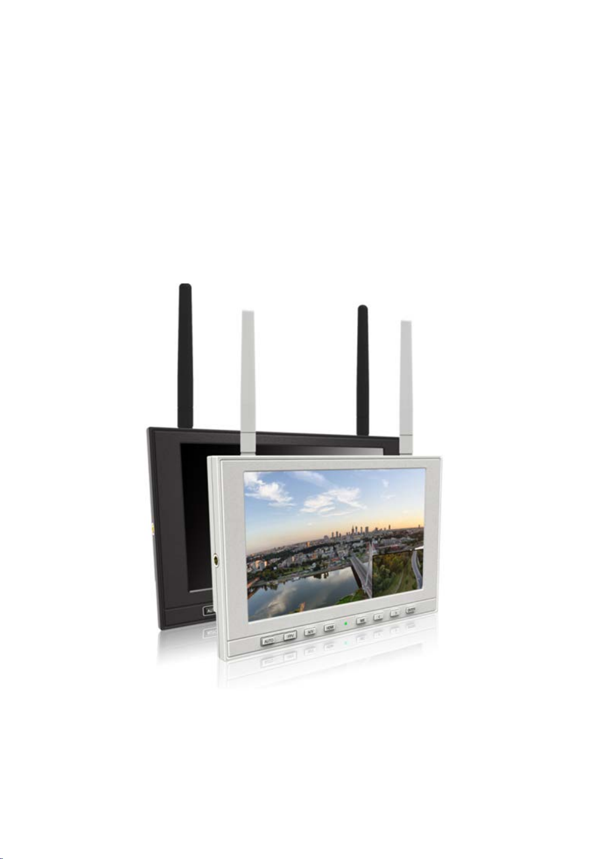
FPV MONITOR
User Manual
Page 2

Important Safe t y In stru ct i ons :
YP-01150116
Please read User Guide before using this product.
Please keep User Guide for future reference.
Please read the cautions to prevent possible danger and loss of property.
Contents
FEATURES...................................................................................................................................... 2
CAUTIONS ..................................................................................................................................... 2
INITIAL SETUP ............................................................................................................................. 3
PRODUCT DE SCRIPTION .......................................................................................................... 4
AERIAL PHOTOGRAPHY SIGNAL RECEIVER ..................................................................... 6
WIRING INSTRUCTIONS ........................................................................................................... 7
MENU SETTING ............................................................................................................................ 8
PAPAMETERS .............................................................................................................................. 12
TROUBLE SHO OT I NG .............................................................................................................. 12
1
Page 3

FEATURES
High resolution: 1280×800;
High brightness: 400cd/㎡;
High contrast: 800:1;
Dual 5.8GHz receivers for optional;
Channel auto searching;
Auto antenna switching to get best signal;
Multiple Picture-in-Picture (PIP) modes;
4-hour timer & alert indicator.
CAUTIONS
Please do not place the display screen towards the ground.
Please avoid heavy impact or drop onto the ground.
Please do NOT use chemical solutions to clean this product. Please wipe
with a clean soft cloth to maintain the brightness of the surface.
Please do not block any vent hole and antenna port.
Please follow the instructions and trouble-shootings to adjust the product.
Other improper adjustment may result in damage. Any further adjustment
must be performed or conducted by a qualified technician.
Please unplug the power and remove the battery if long-term no-use, or
thunder weather.
2
Page 4
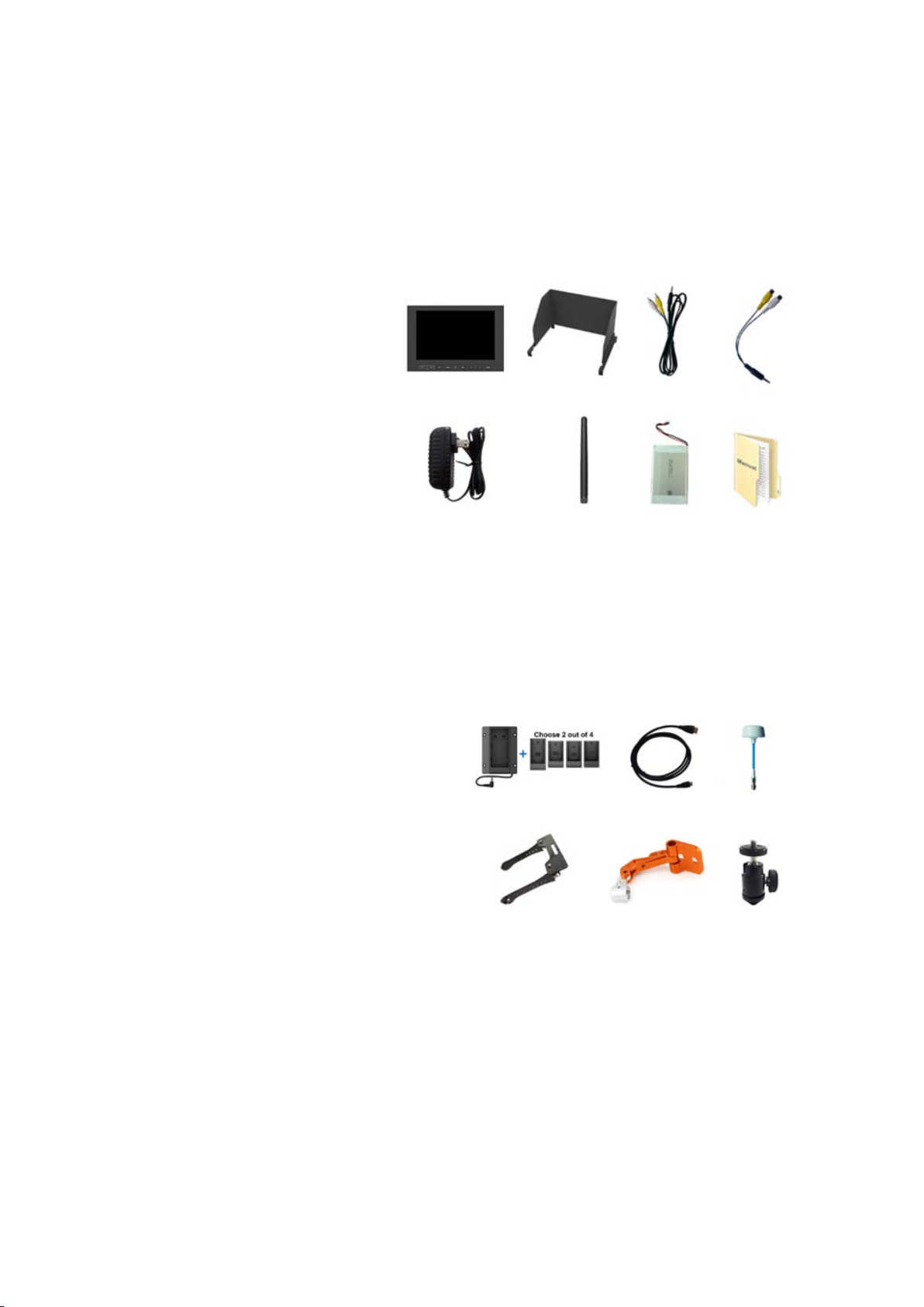
INITIAL SETUP
Unpacking
Carefully unpack the monitor and verify that the following items are included:
Monitor
Sun shade
AV input cable
AV output cable
12V DC adapter
5.8G antenna
2600mAh built-in battery
Manual
Inspect the unit for any physical damage that may have occurred during shipping.
Should there be any damage, please immediately contact us.
Optional Accessories
Additional accessory options for extra requirements. (Available at additional cost)
VESA battery plate + Battery plate
HDMI cable
5.8GHz omnidirectional antenna
FPV double-rod bracket
FPV single-rod bracket
Shoe mount
Tips: Recommend using our company's original accessories to prevent device
from damage.
3
Page 5
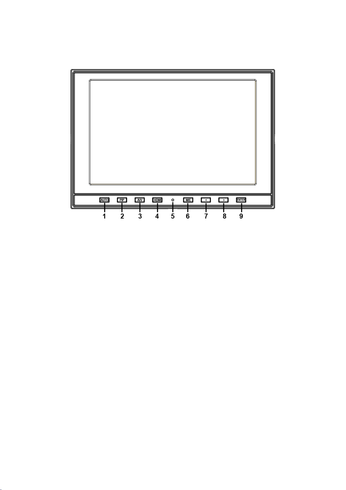
PRODUCT DESCRIPTION
1. AUTO: channel auto searching
2. PIP: picture-in-picture mode.
3. A/V: video& 5.8G switch.
4. HDMI: switch to HDMI state.
5. Battery indicator
Status 1: the indicator light turns to fully red when battery charging.
Status 2: the indicator light turns to half red when powered with DC
power, but not with battery.
Status 3: the indicator light turns to off when charge completely or
use only with battery.
6. M/E: to activate OSD (on-screen display) menu.
Select switch the brightness, contrast, saturation, Tint, sharpness,
volume, MENU and Exit.
7. < Left selection key, to select items on OSD menu and value
option adjustment:
Press to adjust the brightness, contrast, saturation, Tint, sharpness
and volume value decrease.
8. > Right selection key, to select items on OSD menu, value
option adjustment and confirmation:
Press to adjust the brightness, contrast, saturation, Tint, sharpness
and volume value increase.
9. ENTER.
4
Page 6

1. Antenna port.
2. Frequency control.
(Please refer to aerial photography signal receiver)
3. OUT: video output interface.
4. IN: video input interface.
5. Bracket mount (Depth limit 0.5cm).
6. Earphone jack.
7. HDMI input interface.
8. POWER: DC12V power input.
1. VESA mounting interface.
2. Speaker.
3. 2600mA battery slot (built-in).
5
Page 7

AERIAL PHOTOGRAPHY SIGNAL RE CEIVER
Frequency / L.O.
CS1
CS2
CS3
S1
S2
Band 1
B1:5.865GHz/5.385GHz
1 1 1 0 0
B2:5.845GHz/5.365GHz
0 1 1 0 0
B3:5.825GHz/5.345GHz
1 0 1 0 0
B4:5.805GHz/5.325GHz
0 0 1 0 0
B5:5.785GHz/5.305GHz
1 1 0 0 0
B6:5.765GHz/5.285GHz
0 1 0 0 0
B7:5.745GHz/5.265GHz
1 0 0 0 0
B8:5.725GHz/5.245GHz
0 0 0 0 0
Band 2
C1:5.733GHz/5.253GHz
0 0 0 1 0
C2:5.752GHz/5.272GHz
1 0 0 1 0
C3:5.771GHz/5.291GHz
0 1 0 1 0
C4:5.790GHz/5.310GHz
1 1 0 1 0
C5:5.809GHz/5.329GHz
0 0 1 1 0
C6:5.828GHz/5.348GHz
1 0 1 1 0
C7:5.847GHz/5.367GHz
0 1 1 1 0
C8:5.866GHz/5.386GHz
1 1 1 1 0
Band 3
D1:5.705GHz/5.225GHz
0 0 0 0 1
D2:5.685GHz/5.205GHz
1 0 0 0 1
D3:5.665GHz/5.185GHz
0 1 0 0 1
D4:5.645GHz/5.165GHz
1 1 0 0 1
D5:5.885GHz/5.405GHz
0 0 1 0 1
D6:5.905GHz/5.425GHz
1 0 1 0 1
D7:5.925GHz/5.445GHz
0 1 1 0 1
D8:5.945GHz/5.465GHz
1 1 1 0 1
Band 4
A1:5.740GHz/5.260GHz
0 0 0 1 1
A2:5.760GHz/5.280GHz
1 0 0 1 1
A3:5.780GHz/5.300GHz
0 1 0 1 1
A4:5.800GHz/5.320GHz
1 1 0 1 1
A5:5.820GHz/5.340GHz
0 0 1 1 1
A6:5.840GHz/5.360GHz
1 0 1 1 1
A7:5.860GHz/5.380GHz
0 1 1 1 1
Frequency Chart
0: ON; 1:OFF
6
Page 8

Frequency Control Demo
×
√
*339/DW TIPS:
To avoid adjacent frequency disturbance, please ensure two transmitters frequency difference
more than 20MHz.
For example: (ANT1) 5800MHz - (ANT2) 5790MHz = 10MHz < 20MHz (
(ANT1) 5828MHz - (ANT2) 5790MHz = 38MHz > 20MHz (
)
)
Wireless Signal Receiving Antenna
Connecting 5.8GHz antenna or omnidirectional antenna with antenna port on
device.
Activate channel auto searching function by pressing “AUTO” button to receive
audio and video signal.
Or adjust the frequency control manually to comply with channel of transmitter to
receive audio and video signal.
WIRING INSTRUCTIONS
Video Output Cable
1. Video output interface.
2. Yellow: video 1 output plug.
3. White: video 2 output plug.
7
Page 9

Video Input Cable
1. Video input interface.
2. Yellow: video 1 input plug.
3. White: video 2 input plug.
MENU SETTING
Before setting the functions, please make sure the device is connected correctly.
Shortcut keys
The image menu
When power on, press “< / >” key on the device, brightness will appear at
the bottom of the screen, then press the MENU button to select brightness,
sharpness, contrast, saturation, volume, tint, MENU and Exit. User can adj ust
the parameters of the selected item with “< / >”button to meet their needs.
AUTO
Activate channel auto searching function by pressing “AUTO” button on dev ice
when transmitter starts.
Icon Display
Icons will display on screen when signal connected.
Select “Marker” on menu, and turn off “FPV M arker. And the icons
will be invisible on screen.”
Battery: battery level indicator.
Voltage: voltage indicator (invisible when charging)
Timer: available for flying countdown or battery level countdown.
Channel frequency: searching channel automatically.
Signal: wireless signal sensitivity indicator.
8
Page 10

Menu Operation
ITEMS
OPTIONS
Brightness
0 – 100
Contrast
0 – 100
Saturation
0 – 100
Tint
0 – 100
Sharpness
0 – 100
Color T emp
6500K, 7300K, 9300K, User
Color T emp R
Note: Available only under
Color T emp G
Color T emp B
When power on, press “MENU” on the device. The menu of function
setting will display on the screen.
Press < / > buttons to choose menu; then press ENTER to confirm; after
that, press MENU to return.
PICTURE
“User” mode to choose the
color value you need.
9
Page 11

MARKER
ITEMS
OPTIONS
Center Marker
ON, OFF
Safety Marker
OFF, 95%, 93%, 90%, 88%, 85%, 80%
FPV Marker
ON, OFF
ITEMS
OPTIONS
Aspect Ratio
Full Screen, 4: 3, 16: 9, 1.85: 1, 2.35: 1
Pixel-to-Pixel
ON, OFF
Underscan
ON, OFF
Zoom
OFF, ×2, ×4, ×6, ×8
Image Flip
OFF, H, V, H / V
Freeze Input
ON, OFF
PIP Mode
Small, Medium, Large, PBP, POP
DISPLAY
10
Page 12

DSLR AUX & AUDIO
ITEMS
OPTIONS
Camera
ON, OFF ( Only HDMI mode)
H / V Delay
OFF, H&V, V, H
Check Field
OFF, Mono, Red, Green, Blue
Color Bar
ON, OFF
Volume
0 – 100
ITEMS
OPTIONS
Language
English, Chinese
LOGO
ON, OFF
Back Light
0 – 100
Time
0 – 240 (Minute)
Manufacture Default
ON, OFF
ISP
SYSTEM
11
Page 13

PAPAMETERS
Panel
7” LED Backlit ( IPS )
Physical Resolution
1280×800
Brightness
400cd/㎡
Contrast
800:1
Viewing Angle
178°/178°(H/V)
Input Voltage
DC 7~24V
Aspect Ratio
16:9
Current
1300mA
Power Consumption
≤18W
Operating Temperature
-20
Storage Temperature
-30
Dimension (LWD)
185×126×30 (mm)
Weight
385g
TROUBLE SHOOTING
℃~ 60℃
℃~ 70℃
1. Only black-and-white display:
Check whether the brightness or color saturation is properly setup or not.
2. No image:
Check the power input and connection
Check whether the channel of transmitter and receiver are the same or not
Wrong channel frequency when using DJI transmitter:
3.
Please following with the frequency control chart below.
4. Wrong channel when auto searching:
Perhaps much stronger signal comes from near channel will be found when signal
sent by transmitter under channel auto searching function.
Note: due to constant effort to improve products and product
feature s, specifica tions may cha nge without notice.
12
Page 14

13
 Loading...