

Page 1
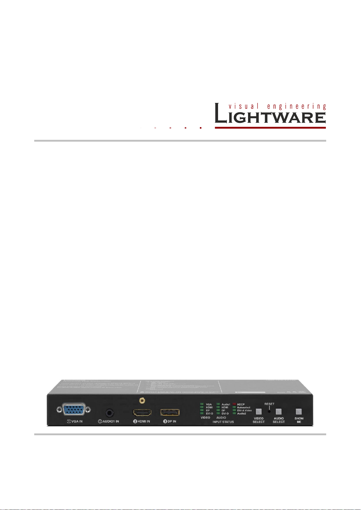
UMX-TPS-TX120
UMX-TPS-TX130
UMX-TPS-TX140
User’s Manual
Page 2

Page 3

SAFETY INSTRUCTIONS
Class II apparatus construction.
This equipment should be operated only from power source indicated on the product.
To disconnect safely from power, remove the power cord from the rear of the equipment,
or from the power source. The MAINS plug is used as the disconnect device, the disconnect
device shall remain readily operable.
There are no user-serviceable parts inside of the unit. Removal of the bottom cover will
expose dangerous voltages. To avoid personal injury, do not remove the bottom cover. Do
not operate the unit without the cover installed.
The apparatus shall not be exposed to dripping or splashing and that no objects filled with
liquids, such as vases, shall be placed on the apparatus.
The apparatus must be safely connected to multimedia systems. Follow instructions
described in this manual.
WEEE ( Waste Electrical & Electronic Equipment )
UMX-TPS-TX100 series
User’s Manual
Correct Disposal of This Product
This marking shown on the product or its literature, indicates that it should not be disposed
with other household wastes at the end of its working life. To prevent possible harm to the
environment or human health from uncontrolled waste disposal, please separate this from
other types of wastes and recycle it responsibly to promote the sustainable reuse of
material resources.
Household users should contact either the retailer where they purchased this product, or
their local government office, for details of where and how they can take this item for
environmentally safe recycling.
Business users should contact their supplier and check the terms and conditions of the
purchase contract. This product should not be mixed with other commercial wastes for
disposal.
Section 1. Introduction Page 3 / 92
Page 4

DECLARATION OF CONFORMITY
We,
Lightware Kft. 1071 Budapest Peterdy str. 15 HUNGARY
as manufacturer declare, that the products
UMX-TPS-TX120
UMX-TPS-TX130
UMX-TPS-TX140
( Computer Monitor Extender )
in accordance with the EMC Directive 2004/108/EC and the Low Voltage Directive
2006/95/EEC are in conformity with the following standards:
EMI/EMC ...................................... EN 55022 Class B
Safety ........... UL, CUL, GS, CR, RCM, PSE, Class II
Date: 02 September 2014
Name: Gergely Vida ( Managing Director )
Signed:
Page 4 / 92 Section 1. Introduction
Page 5

UMX-TPS-TX100 series
Table of contents
1. INTRODUCTION ...................................................................................................................... 9
1.1. BOX CONTENTS................................................................................................................... 9
1.2. DESCRIPTION...................................................................................................................... 9
1.3. FEATURES ........................................................................................................................ 10
1.4. MODEL COMPARISON ........................................................................................................ 11
1.5. COMPATIBLE DEVICES ....................................................................................................... 11
2. CONTROLS AND CONNECTIONS ....................................................................................... 12
2.1. FRONT VIEW ..................................................................................................................... 12
2.1.1. UMX-TPS-TX120 .................................................................................................... 12
2.1.2. UMX-TPS-TX130 .................................................................................................... 12
2.1.3. UMX-TPS-TX140 .................................................................................................... 12
2.2. FRONT VIEW LEGEND......................................................................................................... 13
2.3. REAR VIEW ....................................................................................................................... 14
2.3.1. UMX-TPS-TX120 .................................................................................................... 14
2.3.2. UMX-TPS-TX130 .................................................................................................... 14
2.3.3. UMX-TPS-TX140 .................................................................................................... 14
2.4. REAR VIEW LEGEND .......................................................................................................... 15
2.5. ELECTRICAL CONNECTIONS ............................................................................................... 16
2.5.1. DVI input ................................................................................................................. 16
2.5.2. HDMI input .............................................................................................................. 16
2.5.3. DisplayPort input ..................................................................................................... 17
2.5.4. VGA input ................................................................................................................ 17
2.5.5. Ethernet port ........................................................................................................... 18
2.5.6. TPS output connector ............................................................................................. 18
2.5.7. RS-232 connector ................................................................................................... 19
2.5.8. General purpose input/output ports (GPIO) ............................................................ 19
2.5.9. Audio / Audio1 input ................................................................................................ 19
2.5.10. Audio2 input ............................................................................................................ 20
2.5.11. DC +12V connection ............................................................................................... 20
2.5.1. IR connector ............................................................................................................ 20
User’s Manual
3. TECHNOLOGIES ................................................................................................................... 21
3.1. BASICS ............................................................................................................................. 21
3.1.1. Common problems related to EDID ........................................................................ 21
3.2. ADVANCED EDID MANAGEMENT ........................................................................................ 22
3.3. HDCP MANAGEMENT ........................................................................................................ 22
3.3.1. Protected and unprotected content ......................................................................... 22
3.3.2. Real life examples ................................................................................................... 23
4. INSTALLATION ..................................................................................................................... 24
4.1. MOUNTING ....................................................................................................................... 24
4.2. REMOTE POWERING (POE) ................................................................................................ 24
4.3. CONNECTING DEVICES ...................................................................................................... 24
4.3.1. Connecting steps – using local PSU ....................................................................... 24
4.3.2. Connecting steps – using power injector (TPS-PI-1P1) ......................................... 25
5. FRONT PANEL OPERATIONS ............................................................................................. 26
5.1. FRONT PANEL LEDS ......................................................................................................... 26
5.2. REAR PANEL LEDS ........................................................................................................... 27
5.3. INPUT PORT SELECTION ..................................................................................................... 27
5.3.1. Audio embedding – allowed connections ............................................................... 28
5.3.2. Autoselect – First detect mode ............................................................................... 29
5.3.3. Autoselect – Priority detect mode ........................................................................... 31
5.4. IR INTERFACE ................................................................................................................... 32
5.5. RS-232 MODES ................................................................................................................ 33
5.5.1. Control mode .......................................................................................................... 33
5.5.2. Pass-through mode ................................................................................................. 34
Section 1. Introduction Page 5 / 92
Page 6

5.6. GENERAL PURPOSE INPUT/OUTPUT PORTS (ONLY ON UMX-TPS-TX140) ............................ 34
5.7. SPECIAL FUNCTIONS ......................................................................................................... 34
5.7.1. Control lock ............................................................................................................. 34
5.7.2. Reset to factory default settings ............................................................................. 34
5.7.3. Enable DHCP IP address ....................................................................................... 35
5.7.4. Entering bootload mode .......................................................................................... 35
6. SOFTWARE CONTROL – USING LIGHTWARE DEVICE CONTROLLER (LDC) .............. 36
6.1. STEPS OF THE INSTALLATION IN CASE OF WINDOWS OS ...................................................... 36
6.2. STEPS OF THE INSTALLATION IN CASE OF MAC OS X ........................................................... 38
6.3. LDC UPGRADE ................................................................................................................. 38
6.4. ESTABLISHING THE CONNECTION ....................................................................................... 39
6.5. CROSSPOINT MENU ........................................................................................................... 40
6.6. PORT PROPERTIES AND SETTINGS ...................................................................................... 41
6.6.1. Frame detector (on video input ports) ..................................................................... 41
6.6.2. No sync screen ....................................................................................................... 42
6.6.3. VGA and DVI-A video input port properties ............................................................ 43
6.6.4. TESTPATTERN properties ..................................................................................... 43
6.6.5. Analog audio port properties (Audio, Audio1 and Audio 2) .................................... 43
6.6.6. TPS output port properties and mode settings ....................................................... 44
6.7. EDID MENU ...................................................................................................................... 46
6.8. EDID OPERATIONS ........................................................................................................... 46
6.8.1. Changing emulated EDID ....................................................................................... 46
6.8.2. Learning an EDID ................................................................................................... 47
6.8.3. Exporting an EDID .................................................................................................. 47
6.8.4. Importing an EDID .................................................................................................. 47
6.8.5. EDID Summary window .......................................................................................... 47
6.8.6. Editing an EDID ...................................................................................................... 47
6.8.7. Deleting EDID(s) ..................................................................................................... 48
6.9. CONTROL MENU ................................................................................................................ 48
6.9.1. RS-232 settings ...................................................................................................... 49
6.9.2. GPIO settings (only on UMX-TPS-TX140) ............................................................. 49
6.9.3. Ethernet settings ..................................................................................................... 49
6.10. SETTINGS MENU ................................................................................................................ 49
6.10.1. Status tab ................................................................................................................ 49
6.10.2. Network tab ............................................................................................................. 50
6.10.3. Function buttons ..................................................................................................... 50
6.11. ADVANCED VIEW ............................................................................................................... 51
7. LW2 PROGRAMMER’S REFERENCE ................................................................................. 52
7.1. LW2 PROTOCOL DESCRIPTION ........................................................................................... 52
7.2. GENERAL LW2 COMMANDS ............................................................................................... 52
7.2.1. View product type ................................................................................................... 52
7.2.2. Query control protocol............................................................................................. 52
7.2.3. View firmware version of the CPU .......................................................................... 53
7.2.4. Connection test ....................................................................................................... 53
7.2.5. View serial number ................................................................................................. 53
7.2.6. Compile time ........................................................................................................... 53
7.2.7. View installed board(s)............................................................................................ 53
7.2.8. View firmware for all controllers’ ............................................................................. 53
7.2.9. Restart matrix router ............................................................................................... 54
7.2.10. Query state ............................................................................................................. 54
7.3. CROSSPOINT SWITCHING LW2 COMMANDS......................................................................... 54
7.3.1. Switch one input to one output ............................................................................... 54
7.3.2. Mute specified output .............................................................................................. 55
7.3.3. Unmute specified output ......................................................................................... 55
7.3.4. Lock the output ....................................................................................................... 55
7.3.5. Unlock the output .................................................................................................... 55
7.3.6. View connection state on the output ....................................................................... 56
7.3.7. View crosspoint size ............................................................................................... 56
7.3.8. Query video Autoselect mode ................................................................................. 56
Page 6 / 92 Section 1. Introduction
Page 7

UMX-TPS-TX100 series
User’s Manual
7.3.9. Change video Autoselect mode .............................................................................. 57
7.3.10. Query audio Autoselect mode ................................................................................ 57
7.3.11. Change audio Autoselect mode .............................................................................. 57
7.3.12. Query video input priorities ..................................................................................... 57
7.3.13. Change video input priorities .................................................................................. 58
7.3.14. Query audio input priorities ..................................................................................... 58
7.3.15. Change audio input priorities .................................................................................. 58
7.3.16. Batch switch outputs ............................................................................................... 59
7.4. RS-232-SPECIFIC LW2 COMMANDS ................................................................................... 59
7.4.1. Query the RS-232 mode ......................................................................................... 59
7.4.2. Change RS-232 mode ............................................................................................ 59
7.4.3. Query the RS-232 port settings (local or link port) ................................................. 60
7.4.4. Change RS-232 port settings (local or link port) ..................................................... 60
7.4.5. Query the RS-232 protocol (local or link port) ........................................................ 61
7.4.6. Change RS-232 protocol (local or link port) ........................................................... 61
7.5. FURTHER LW2 COMMANDS ............................................................................................... 61
7.5.1. Query the IP status ................................................................................................. 61
7.5.2. Query the IP address .............................................................................................. 62
7.5.3. Set the IP address .................................................................................................. 62
7.5.4. Query the subnet mask ........................................................................................... 62
7.5.5. Set the subnet mask ............................................................................................... 62
7.5.6. Query the gateway address .................................................................................... 62
7.5.7. Set the gateway address ........................................................................................ 63
7.5.8. Query the TCP/IP port ............................................................................................ 63
7.5.9. Set the TCP/IP port ................................................................................................. 63
7.5.10. Query the state of a GPIO pin ................................................................................ 63
7.5.11. Set the state of a GPIO pin ..................................................................................... 64
8. LW3 PROGRAMMERS’ REFERENCE ................................................................................. 65
8.1. OVERVIEW ........................................................................................................................ 65
8.1.1. Elements of the tree structure ................................................................................. 65
8.1.2. Escaping ................................................................................................................. 67
8.1.3. Error messages ....................................................................................................... 68
8.1.4. Prefix summary ....................................................................................................... 68
8.2. THE TREE STRUCTURE OF UMX-TPS DEVICES ................................................................... 69
8.3. LW3 COMMANDS .............................................................................................................. 69
8.3.1. Get command ......................................................................................................... 69
8.3.2. Set command .......................................................................................................... 71
8.3.3. Invocation ................................................................................................................ 71
8.3.4. Manual .................................................................................................................... 72
8.3.5. Signature ................................................................................................................. 73
8.3.6. Subscription ............................................................................................................ 73
8.3.7. Notifications about the changes of the properties .................................................. 74
8.4. MEDIA LAYER PROPERTIES ................................................................................................ 75
8.4.1. SublayerCount ........................................................................................................ 75
8.4.2. PortCount ................................................................................................................ 75
8.4.3. PortMap .................................................................................................................. 75
8.4.4. ActiveSublayerMask ............................................................................................... 75
8.4.5. P1-P7 – port numbers ............................................................................................. 76
8.5. AUDIO AND VIDEO SWITCHING ............................................................................................ 76
8.5.1. Query current video crosspoint setting ................................................................... 76
8.5.2. Query current audio crosspoint setting ................................................................... 76
8.5.3. Switching video input .............................................................................................. 76
8.5.4. Switching audio input .............................................................................................. 77
8.5.5. Query the Autoselect settings ................................................................................. 77
8.5.6. Change the Autoselect mode ................................................................................. 77
8.5.7. Query the input port priority .................................................................................... 78
8.5.8. Changing the input port priority ............................................................................... 78
8.6. SERIAL PORT CONFIGURATION ........................................................................................... 79
8.6.1. Protocol setting ....................................................................................................... 79
8.6.2. BAUD rate setting ................................................................................................... 79
Section 1. Introduction Page 7 / 92
Page 8

8.6.3. Databits setting ....................................................................................................... 79
8.6.4. Stopbits setting ....................................................................................................... 80
8.6.5. Parity setting ........................................................................................................... 80
8.6.6. RS232 operation mode (Control/Pass) ................................................................... 80
8.7. EDID MANAGEMENT .......................................................................................................... 81
8.7.1. Query the emulated EDIDs ..................................................................................... 81
8.7.2. Query the header of the Dynamic EDID ................................................................. 81
8.7.3. Query the validity of the Dynamic EDID ................................................................. 81
8.7.4. Query a User or a Factory EDID header ................................................................ 81
8.7.5. Emulating an EDID to an input port ........................................................................ 82
8.7.6. Copy an EDID to User memory .............................................................................. 82
8.7.7. Deleting an EDID from user memory ...................................................................... 82
8.7.8. Resetting emulated EDIDs to factory default – a választ kell csekkolni ................. 82
9. SPECIFICATIONS ................................................................................................................. 83
9.1. MECHANICAL DRAWINGS.................................................................................................... 86
9.2. MAXIMUM TWISTED PAIR DISTANCES .................................................................................. 87
9.3. FACTORY DEFAULT SETTINGS ............................................................................................ 87
9.4. FACTORY EDID LIST ......................................................................................................... 89
9.5. INPUT/OUTPUT PORT NUMBERING ....................................................................................... 90
9.5.1. UMX-TPS-TX120 .................................................................................................... 90
9.5.2. UMX-TPS-TX130 .................................................................................................... 90
9.5.3. UMX-TPS-TX140 .................................................................................................... 91
10. VERSION APPLICABILITY ................................................................................................... 92
11. WARRANTY .......................................................................................................................... 92
12. DOCUMENT REVISION HISTORY ....................................................................................... 92
Page 8 / 92 Section 1. Introduction
Page 9
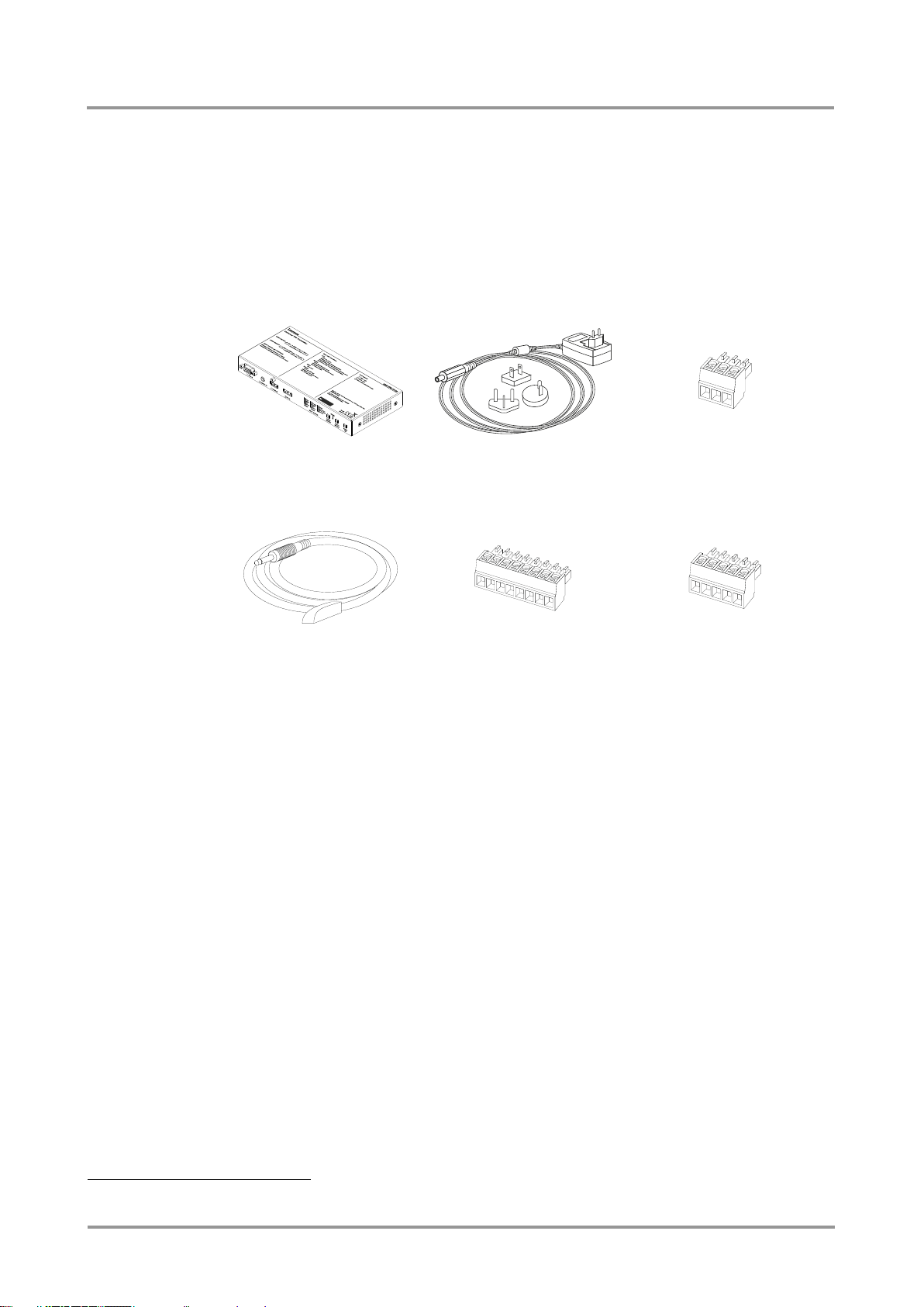
UMX-TPS transmitter unit
+12V DC adaptor with
interchangeable plugs
Phoenix® Combicon
3-pole connector
Infrared transmitter with
TRS male connector
Phoenix® Combicon
8-pole connector1
Phoenix® Combicon
5-pole connector2
1
2
1. Introduction
Thank You for choosing Lightware UMX-TPS transmitter. The products have HDBaseTTM
integration with additional Lightware developments. UMX-TPS devices transmit universal
video at a resolution up to 4K, audio and control up to 170 m distance over a single CAT
cable. The transmitters are compatible with Lightware TPS matrix boards and other TPS
products.
1.1. Box contents
UMX-TPS-TX100 series
User’s Manual
1.2. Description
This transmitter was designed to extend digital and analog video signals (e.g. VGA, YPrPb,
HDMI 1.4 and DP 1.1) and audio signals (analog stereo audio from local inputs or
embedded 7.1 HBR audio). Video signals with HDCP encryption are also supported.
Analog signals (both audio and video) are converted to a digital format and can be
transmitted separately from each other.
Using the factory, custom or transparent EDID emulation the user can fix and lock EDID
data on each input connector. Advanced EDID Management forces the required resolution
from any video source and fixes the output format conforming to the system requirements.
The unit offers bi-directional and transparent IR, RS-232 and Ethernet transmission.
Furthermore, the IR and RS-232 connection supports command injection, allowing it to
send any IR or RS-232 control command directly from the LAN connection.
Remote powering (Power over Ethernet) is available through a single CAT cable, but local
power supply can also be used. The device can be mounted on a rack shelf or used
standalone. Due to Lightware’s attentive design UMX-TPS-TX100 series is compatible with
both the HDBaseTTM extenders and matrix switchers.
Only for UMX-TPS-TX130 and UMX-TPS-TX140
Only for UMX-TPS-TX140
Section 1. Introduction Page 9 / 92
Page 10

1.3. Features
Certain features depend on the configuration of the model. For more information about the
models see section 1.4 on page 11.
3D and 4K support – High bandwidth allows extension of resolutions up to 4K and
even 3D sources and displays are supported.
Signal transmission up to 170 m – Video and audio signal transmission (DVI,
HDMI, VGA or DisplayPort, and Ethernet+RS-232+Infra-Red over a single
CAT5e…CAT7e cable.
Various audio and video connectors – DVI-I, HDMI, VGA, DisplayPort, Stereo
jack, PHOENIX 1x5 pole.
GPIO control port – 7 GPIO pins operating at TTL digital signal levels and can be
controlled with both LW2 and LW3 commands.
HDCP compliant – UMX-TPS-TX100 series fulfils HDCP standard. HDCP can be
disabled when not protected content is extended.
Advanced EDID management – User can emulate any EDID on the input ports,
read out and store any monitor's EDID in the internal memory.
Pixel Accurate Reclocking – (removes jitter caused by long cables) The output
has a clean, jitter free signal, eliminating signal instability and distortion caused by
long cables or connector reflections.
Frame detector and signal analysis – Using Lightware Device Controller
software the exact video and audio signal format can be determined such as timing,
frequencies, scan mode, HDCP encryption, color range, color space and audio
sample rate.
Deep Color support and conversion – It is possible to transmit the highest quality
36-bit video streams for perfect color reproduction.
DVI/HDMI conversion – The transmitter is able to convert from HDMI to DVI
signals so that you can watch HDMI videos on your computer display without audio.
Bi-directional RS-232 pass-through – AV systems can also contain serial port
controllers and controlled devices. Serial port pass-through supports any unit that
works with standard RS-232.
Remote power – The transmitters are PoE-compatible and can be powered locally
by the supplied power adaptor, or remotely via the TPS connection (through the
CATx cable) with a compatible Power Source Equipment.
Locking DC connector – Special plug of wall adaptor ensures safe power supply.
This type of connector prevents unwanted extractions.
Separate Audio and Video switching – Video and audio signals are separated
and can be switched independently.
Analog Audio and Video A/D conversion – Analog audio and video signal is
converted to digital and placed it to the output.
Input (video & audio) status LEDs – Front panel LEDs give feedback about state
of the unit and the video and audio signals.
Accepts analog and digital audio signals - Accepts analog stereo; 5.1 S/PDIF
and even 7.1 HDMI embedded audio signals. Analog signals are converted to
digital formats and digital or digitized analog audio can be embedded in the video
stream.
Auto-switch function for video and audio inputs – Autoselect mode with or
without priority can toggles between inputs. It helps the handling of the transmitter
and installation of new devices.
Page 10 / 92 Section 1. Introduction
Page 11

Video ports
Audio ports
Interface ports
HDMI
input
VGA
input
DVI-I
input
DP
input
Jack
3.5 in
Phoenix
in
Ethernet
Infra
RS-232
GPIO
UMX-TPS-TX120
-
-
-
-
UMX-TPS-TX130
-
-
UMX-TPS-TX140
1.4. Model comparison
1.5. Compatible devices
UMX-TPS-TX100 series transmitters are compatible with the following receivers and input
boards:
MX modular matrix frames with MX-TPS-IB
HDMI-TPS-RX90
UMX-TPS-TX100 series
User’s Manual
Table 1-1. Features of UMX-TPS-TX100 series
MODEX TPS family
DVI-HDCP-TPS-RX95
HDMI-TPS-RX95
Section 1. Introduction Page 11 / 92
Page 12
1
VGA in
4
Status LEDs
6
Reset
7
Audio select
8
Show me
5
Video select
3
HDMI in
2
Audio in
1
VGA in
4
Status LEDs
6
Reset
7
Audio select
8
Show me
5
Video select
3
HDMI in
2
Audio in
1
VGA in
4
Status LEDs
6
Reset
7
Audio select
8
Show me
5
Video select
3
HDMI in
2
Audio in
9
DP in
2. Controls and connections
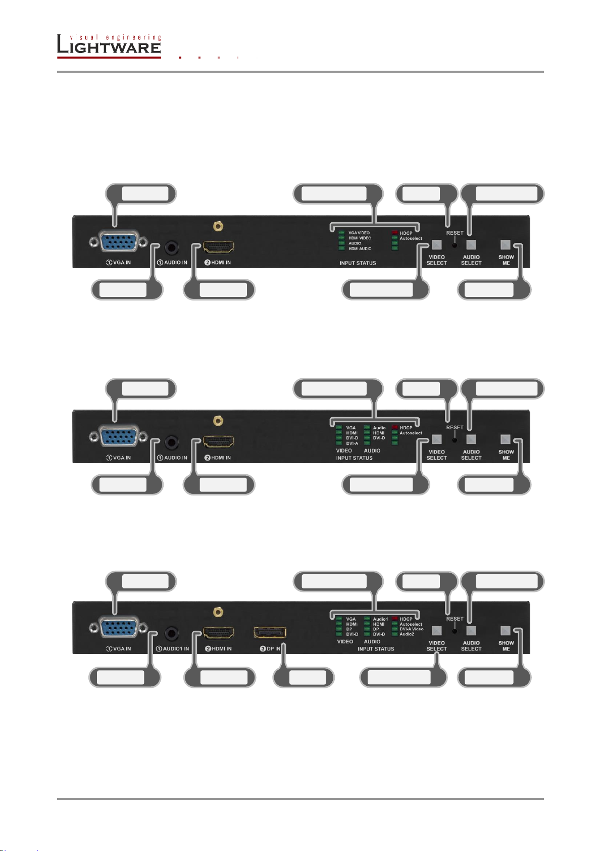
2.1. Front view
2.1.1. UMX-TPS-TX120
2.1.2. UMX-TPS-TX130
2.1.3. UMX-TPS-TX140
Page 12 / 92 Section 2. Controls and connections
Page 13

6
4 2 3
1
5
7 8 9
2.2. Front view legend
VGA in Connect a VGA cable between the analog video source and the
Audio in / Audio1 in 3.5 mm Jack connector for asymmetric analog audio input signal.
HDMI in Connect a HDMI cable between the source and the transmitter.
Status LEDs The LEDs give a feedback about the state of the unit, the video
Video select Switching among video inputs is available with this button.
Reset Reset button reboots the extender. This is the same like
UMX-TPS-TX100 series
User’s Manual
transmitter unit. Pin assignment can be found in section 2.5.4 on
page 17.
Pin assignment can be found in section 2.5.9 on page 19.
Applied cable shall not be more, than 30 m (when signal is
1080p) and 15 m (when signal is 4K). Pin assignment can be
found in section 2.5.2 on page 16.
and audio signals. For more information see section 5.1 on page
26.
disconnect from power source and reconnect again.
Audio select Switching between audio inputs is available with this button.
Show me Special functions are available with this button (switch to
bootload mode, enable DHCP, restore factory default settings).
For details about the special functions see the section 5.7 on
page 34.
DP in DisplayPort input connector (only on UMX-TPS-TX140). Applied
cable shall not be more, than 30 m (at 2.7 Gbps data speed). Pin
assignment can be found in section 2.5.3 on page 17.
Section 2. Controls and connections Page 13 / 92
Page 14
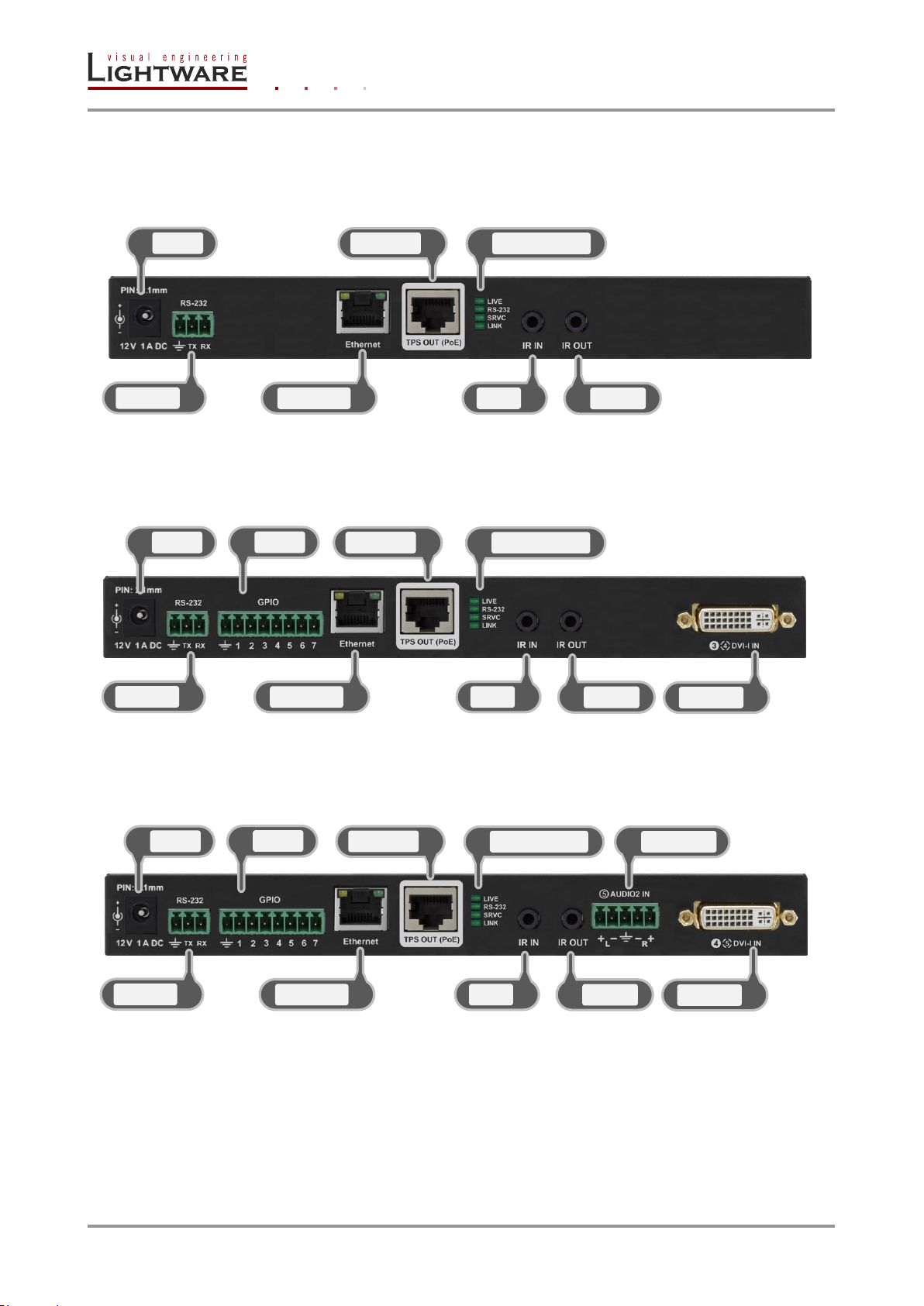
2.3. Rear view
1
DC in
4
TPS out
5
Status LEDs 2
RS-232
3
Ethernet 6
IR in
7
IR out
1
DC in
4
TPS out
5
Status LEDs 2
RS-232
3
Ethernet
6
IR in
7
IR out
8
GPIO
9
DVI-I in
1
DC in
4
TPS out
5
Status LEDs
2
RS-232 3
Ethernet 6
IR in
7
IR out
8
GPIO
9
DVI-I in
10
Audio2 in
2.3.1. UMX-TPS-TX120
2.3.2. UMX-TPS-TX130
2.3.3. UMX-TPS-TX140
Page 14 / 92 Section 2. Controls and connections
Page 15

6
4
2
3
1
5
7
8
9
10
2.4. Rear view legend
DC in Connect the output of the supplied +12V DC power adaptor or
RS-232 3-pole Phoenix connector for RS-232 serial port. Pin assignment
Ethernet Locking RJ45 connector. Remote control port for connecting the
TPS out Locking RJ45 connector. Connect a twisted pair cable between
Status LEDs The LEDs give immediate feedback about device’s state, RS-232
UMX-TPS-TX100 series
User’s Manual
use Lightware’s rack mountable Power supply unit
(PSUx10-200-12V or PSUx20-400-12V).
can be found in section 2.5.7 on page 19.
extender to a Local Area Network (LAN). Pin assignment can be
found in section 2.5.5 on page 18.
the transmitter and the receiver. Remote powering also happens
through this connector. Pin assignment can be found in section
2.5.6 on page 18. Maximum twisted pair distances can be found
in section 9.2 on page 87.
and TPS link state. For more information see section 5.2 on page
27.
IR in 3-pole TRS connector, also known as 3.5 mm (1/8”) jack plug for
IR out 3-pole TRS connector, also known as 3.5 mm (1/8”) jack plug for
GPIO 8-pole Phoenix connector for configurable general purpose
DVI-I in 29-pole DVI-I connector for DVI-D and DVI-A signal (only on
Audio2 in 5-pole Phoenix connector (only on UMX-TPS-TX140) for
optional IR receiver only. Pin assignment can be found in section
2.5.1 on page 20.
optional IR transmitter only. Pin assignment can be found in
section 2.5.1 on page 20.
input/output ports. Pin assignment can be found in section 2.5.8
on page 19.
UMX-TPS-TX130 and UMX-TPS-TX140). Applied cable shall not
be more, than 30 m (when signal is 1080p) and 15 m (when
signal is 4K). Pin assignment can be found in section 2.5.1 on
page 16.
symmetrical analog audio input. Pin assignment can be found in
section 2.5.10 on page 20.
Section 2. Controls and connections Page 15 / 92
Page 16
2.5. Electrical connections
Pin
Signal
Pin
Signal
Pin
Signal
1
TMDS Data2-
9
TMDS Data1-
17
TMDS Data0-
2
TMDS Data2+
10
TMDS Data1+
18
TMDS Data0+
3
TMDS Data2/4 Shield
11
TMDS Data1/3 Shield
19
TMDS Data0/5 Shield
4
TMDS Data4-
12
TMDS Data3-
20
TMDS Data5-
5
TMDS Data4+
13
TMDS Data3+
21
TMDS Data5+
6
DDC Clock
14
+5V Power
22
TMDS Clock Shield
7
DDC Data
15
GND (for +5V)
23
TMDS Clock+
8
Analog Vertical Sync
16
Hot Plug Detect
24
TMDS Clock-
C1
Analog Red
C2
Analog Green
C3
Analog Blue
C4
Analog Horizontal Sync
C5
GND
HDMI Type A receptacle
HDMI Type A Plug
Pin
Signal
Pin
Signal
1
TMDS Data2+
11
TMDS Clock Shield
2
TMDS Data2 Shield
12
TMDS Clock–
3
TMDS Data2–
13
CEC
4
TMDS Data1+
14
Reserved
5
TMDS Data1 Shield
15
SCL
6
TMDS Data1–
16
SDA
7
TMDS Data0+
17
DDC/CEC/HEC Ground
8
TMDS Data0 Shield
18
+5 V Power (max 50 mA)
9
TMDS Data0–
19
Hot Plug Detect
10
TMDS Clock+
1 2 3 4 5 6 7 8 9
10
11
12
13
14
15
16
17
18
19
19
18
17
16
15
14
13
12
11
10
9 8 7 6 5
4
3 2 1
C1
C2
C4
C3
1 2 3
4
5
6 7 8 9 10
11
12
13
14
15
16
17
18
19
20
21
22
23
24
C5
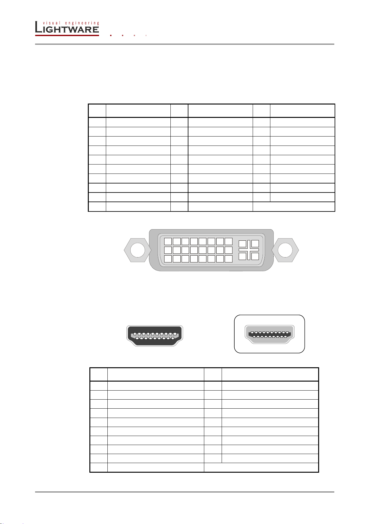
2.5.1. DVI input
UMX-TPS-TX140 provides a 29-pole DVI-I connector as an input. This way, user can plug
in any DVI connector; analog signals (such as VGA or RGBHV) are put through an A/D
conversion. Always use high quality DVI cable for connecting sources.
2.5.2. HDMI input
19-pole HDMI connectors are provided for inputs. Always use high quality HDMI cables.
Table 2-1. DVI-I connector dual link pin assignments
Figure 2-1. DVI-I connector
Page 16 / 92 Section 2. Controls and connections
Table 2-2. HDMI connector pin assignments
Page 17

UMX-TPS-TX100 series
Pin
Signal
Pin
Signal
Pin
Signal
1
ML_Lane 0 (p)
8
GND
15
AUX CH (p)
2
GND
9
ML_Lane 2 (n)
16
GND
3
ML_Lane 0 (n)
10
ML_Lane 3 (p)
17
AUX CH (n)
4
ML_Lane 1 (p)
11
GND
18
Hot Plug
5
GND
12
ML_Lane 3 (n)
19
Return
6
ML_Lane 1 (n)
13
Config1
20
DP_PWR
7
ML_Lane 2 (p)
14
Config2
Pin nr.
Name
Description
1
RED
Red Video (75 ohm, 0.7 V p-p)
2
GREEN
Green Video (75 ohm, 0.7 V p-p)
3
BLUE
Blue Video (75 ohm, 0.7 V p-p)
4
ID2
Monitor ID Bit (Not used, internally connected to Pin 5)
5
GND
Ground
6
RGND
Red Ground (Internally connected to Pin 5)
7
GGND
Green Ground (Internally connected to Pin 5)
8
BGND
Blue Ground (Internally connected to Pin 5)
9
KEY
Optional +5V output from graphics card
10
SGND
Sync Ground (Internally connected to Pin 5)
11
ID0
Monitor ID Bit 0 (Not used, internally connected to Pin 5)
12
SDA
I2C bidirectional data line
13
HSYNC
Horizontal Sync
14
VSYNC
Vertical Sync which works also as data clock
15
SCL
I2C data clock in DDC2
1
5
11
10
6
15
User’s Manual
2.5.3. DisplayPort input
UMX-TPS-TX140 provides a DisplayPort input connector.
Figure 2-2. DisplayPort connector
Table 2-3. DisplayPort connector pin assignments
2.5.4. VGA input
UMX-TPS-TX100 series provides standard 15-pole D-SUB female connector for VGA
inputs. Always use high quality VGA cable for connecting sources and displays.
Figure 2-3. D-SUB 15 pole female connector (DE15F)
Table 2-4. D-sub connector pin assignment for standard VGA
Section 2. Controls and connections Page 17 / 92
Page 18
2.5.5. Ethernet port
LED1 (green)
LED2 (yellow)
Pin nr.
Name
Wire color
OFF
10 Mbit/s
not linked
1 TX +
Green stripe
Blink
-
activity
2 TX -
Green
ON
100 Mbit/s
no activity
3 RX +
Orange stripe
4 Not used
Blue
5 Not used
Blue stripe
6 Rx -
Orange
7 Not used
Brown stripe
8 Not used
Brown
Pin
TIA/EIA
T568 A
color and
name
TIA/EIA
T568 B
color
and name
1
white/green stripe
white/orange stripe
2
green solid
orange solid
3
white/orange stripe
white/green stripe
4
blue solid
blue solid
5
white/blue stripe
white/blue stripe
6
orange solid
green solid
7
white/brown stripe
white/brown stripe
8
brown solid
brown solid
8
1
LED1
LED2
1
8
8
1
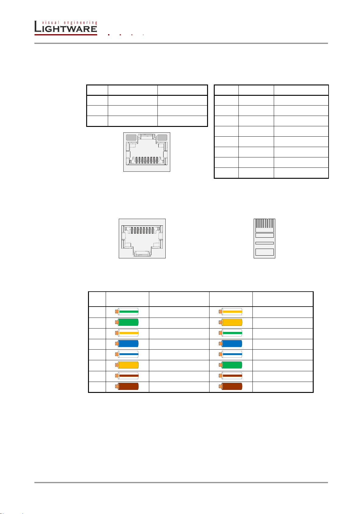
The Ethernet port can be connected to a LAN hub, switch or router by a CATx cable.
However both cable types (straight or cross) are supported and handled by the device,
below pin assignment is recommended.
Figure 2-4. RJ45 connector and pin assignments for Ethernet
2.5.6. TPS output connector
UMX-TPS transmitters provide standard RJ45 connectors for TPS Output.
RJ45 receptacle RJ45 plug
Lightware recommends the termination of TP cables on the basis of TIA/EIA T 568 A or
TIA/EIA T 568 B standards.
Page 18 / 92 Section 2. Controls and connections
Table 2-5. Recommended termination of TP cables
Info: When a standard Ethernet device is connected to the TPS connector for some reason, the
transmitter is switched to Ethernet fallback mode automatically. TPS port is changed to
work as an Ethernet port, but to operate the transmitter this way is not recommended.
Page 19

UMX-TPS-TX100 series
Pin nr.
Signal
Ground
1
TX data
2
RX data
Pin nr.
Signal
Ground
1
Configurable
2 3 4 5 6
7
Pin nr.
Signal
1
Left
2
Right
3
Ground
1
2
1 2 3
4
5 6
7
1 2 3
User’s Manual
2.5.7. RS-232 connector
UMX-TPS extenders contain a 3-pole Phoenix connector, which is used for RS-232 serial
connection. The transmitter has pass-through function, or can be remote controlled.
2-5. Figure RS-232 connector pin assignments
Compatible plug type
Phoenix® Combicon series (3.5mm pitch, 3-pole)
Type: MC 1.5/3-ST-3.5, order nr.: 691361100003 (Würth)
2.5.8. General purpose input/output ports (GPIO)
UMX-TPS-TX130 and UMX-TPS-TX140 have seven GPIO pins, which operates at TTL
digital signal levels and can be controlled with both LW3 and LW2 commands:
Output pin state can be set with a specific command.
Input pin state can be queried; a notification is sent from the device, if the state is
changed.
As a special function, GPIO pins would act the same way as video select, audio select and
show me buttons. As another special function video input can be selected directly with a
GPIO pin; e.g. if GPIO1 input is activated, VGA connector becomes the active input.
Compatible plug type
Phoenix® Combicon series (3.5mm pitch, 8-pole)
Type: MC 1.5/8-ST-3.5, order nr.: 1840421
2.5.9. Audio / Audio1 input
Figure 2-6. GPIO pin assignments
The connector is used for asymmetric analog audio input signal. It is also known as (3.5
mm or approx. 1/8”) audio jack, phone jack, phone plug and mini-jack plug.
Figure 2-7. 3.5 mm Jack audio plug pin assignments
Info: The input is named to „Audio” on UMX-TPS-TX120 and UMX-TPS-TX130, and „Audio1”
on UMX-TPS-TX140.
Section 2. Controls and connections Page 19 / 92
Page 20
2.5.10. Audio2 input
Pin nr.
Signal
1
Left+
2
Left-
3
Ground
4
Right-
5
Right+
Receiver – 3-pole-TRS
Transmitter – 2-pole-TRS
1 Tip
IR Input -
1 Tip
IR Output +
2 Ring
GND
2 Ring
IR Output -
3 Sleeve
IR Input +
3 Sleeve
IR Output -
1 2 3 4 5
1 2 3
1 3
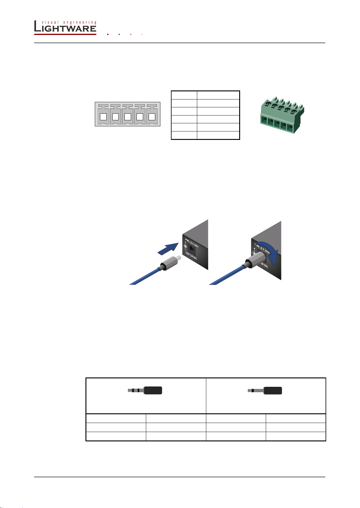
UMX-TPS-TX140 contains a 5-pole Phoenix connector that is used for symmetrical analog
audio input. Asymmetrical audio signals can be connected as well. For asymmetrical
output, connect only + and ground. For asymmetrical input connect + and ground to the
source and connect – to the ground.
Compatible plug type
Phoenix® Combicon series (3.5mm pitch. 5-pole)
Type: MC 1.5/5-ST-3.5, order nr.: 1840395
2.5.11. DC +12V connection
The device has a locking DC connector to establish robust and safe power connection.
After plugging it in, turn the plug clockwise as you can see in the picture below.
Figure 2-8. Audio2 input pin assignments
Do not forget to turn the connector counterclockwise before trying to disconnect the power
adaptor.
Warranty void if damage occurs due to use of a different power source.
Always use the supplied +12V power adaptor or Lightware’s rack mountable power supply.
2.5.1. IR connector
IR receiver and IR transmitter can be connected to the transmitter with TRS (Tip, Ring, and
Sleeve) connectors. They are also known as (3,5 mm or approx. 1/8”) audio jack, phone
jack, phone plug, and mini-jack plug.
Figure 2-9. Locking DC connector
Table 2-6. TRS connector pin assignment
Info: Transmitter’s Ring pole is optional. If your IR Transmitter has three pole TRS plug, then the
Ring and the Sleeve are the same signal (Output - )
Page 20 / 92 Section 2. Controls and connections
Page 21
3. Technologies
3.1. Basics
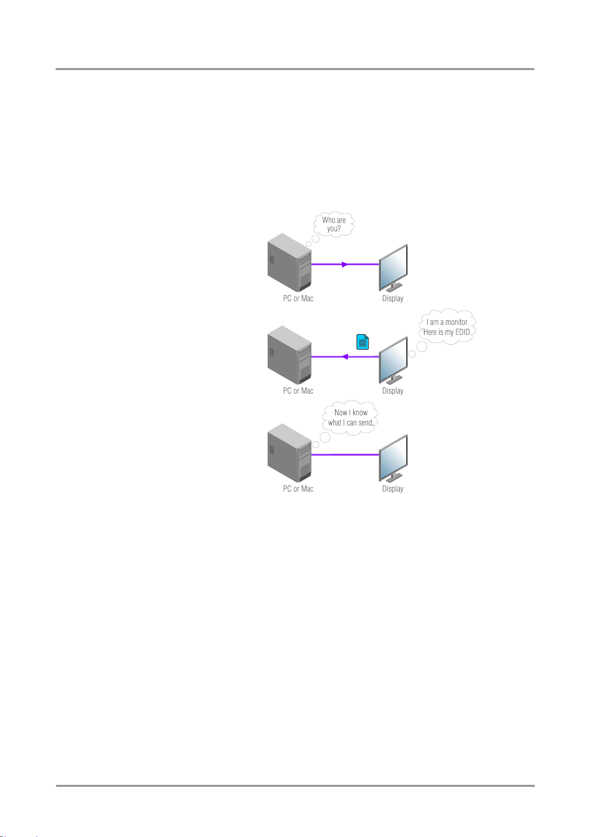
EDID stands for Extended Display Identification Data. Simply put, EDID is the passport of
display devices (monitors, TV sets, projectors). It contains information about the display’s
capabilities, such as supported resolutions, refresh rates (these are called Detailed
Timings), the type and manufacturer of the display device, etc.
After connecting a DVI source to a DVI display, the source reads out the EDID to determine
the resolution and refresh rate of the image to be transmitted.
UMX-TPS-TX100 series
User’s Manual
Figure 3-1. EDID communication
Most DVI computer displays have 128-byte long EDID structure. However, Digital
Televisions and HDMI capable displays may have another 128 bytes, which is called EEDID and defined by CEA (Consumer Electronics Association). This extension contains
information about additional Detailed Timings, audio capabilities, speaker allocation and
HDMI capabilities. It is important to know, that all HDMI capable devices must have CEA
extension, but not all devices are HDMI capable which have the extension.
3.1.1. Common problems related to EDID
Problem: „I have changed to a different EDID on UMX-TPS-TX140 to have a different
resolution but nothing happens.”
Solution: Some graphics cards and video sources read out the EDID only after power-up
and later they don’t sense that EDID has been changed. You need to restart
your source to make it read out the EDID again.
Problem: „I have a UMX-TPS-TX140 and I’m using a Lightware factory preset EDID. I
would like to be able to choose from different resolutions, but my source allows
only one resolution.”
Solution: Most Lightware factory preset EDIDs allow only one resolution, forcing the
sources to output only that particular signal. You need to select the Universal
EDID that supports all common VESA resolutions, see the factory EDID list.
Section 3. Technologies Page 21 / 92
Page 22

3.2. Advanced EDID management
Each DVI sink (e.g. monitors, projectors, plasma displays, and switcher inputs) must
support the EDID data structure. Source BIOS and operating systems are likely to query
the sink using DDC2B protocol to determine what pixel formats and interface are supported.
DVI standard makes use of EDID data structure for the identification of the monitor type
and capabilities. Most DVI sources (VGA cards, set top boxes, etc.) will output DVI signal
after accepting the connected sink’s EDID information. In case of EDID readout failure or
missing EDID, the source will not output DVI video signal.
UMX-TPS-TX100 series provides Lightware’s Advanced EDID Management function that
helps system integration. The transmitter’s built-in memory stores and emulates preprogrammed factory EDIDs, user’s EDID and the monitor's EDID that is connected to the
receiver. The transmitter stores the EDID of the attached monitor or projector in a
non-volatile memory. This way the EDID from a monitor is available when the monitor is
unplugged, or switched off.
The EDID emulated on the HDMI / DVI / DP input can be copied from the transmitter's
memory (static EDID emulation), or from the last attached monitor’s memory (dynamic
EDID emulation). For example, the transmitter can be set up to emulate a device, which is
connected to the receiver’s DVI output. In this case, the EDID is automatically changed, if
the monitor is replaced with another display device (as long as it has a valid EDID).
Advanced EDID management can be controlled via Lightware Device Controller.
Info: The user is not required to disconnect the HDMI / DVI / DP cable to change an EDID as
opposed to other manufacturer’s products. EDID can be changed even if source is
connected to the input and powered ON.
Info: When EDID has been changed, the transmitter toggles the HOTPLUG signal for 2 seconds.
Some sources do not observe this signal, so in this case the change is not recognized by
the source. In such cases, the source device must be restarted or powered OFF and ON
again.
3.3. HDCP management
Lightware Visual Engineering is a legal HDCP adopter. Several functions have been
developed which help to solve HDCP related problems. Complex AV systems often have
both HDCP and non-HDCP components. UMX-TPS-TX extenders allow to transmit HDCP
encrypted and unencrypted signals. The devices will be still HDCP compliant, as they will
never output an encrypted signal to a non-HDCP compliant display device. If an encrypted
signal is switched to a non-compliant output, a red screen alert or muted screen will be
shown.
3.3.1. Protected and unprotected content
Many video sources send HDCP protected signal if they detect that the sink is HDCP
capable – even if the content is not copyrighted. This can cause trouble if a HDCP capable
device (e.g. an extender-pair) is connected between the source and the display. In this
case, the content cannot be viewed on non-HDCP capable displays and interfaces like
event controllers.
Rental and staging technicians often complain about Apple laptops, who always send
HDCP encrypted signals if the receiver device (display, matrix router, etc.) reports HDCP
compliancy. However, HDCP encryption is not required all the time (e.g. computer desktop
image), MacBook and MacBook Pro still do that.
To avoid unnecessary HDCP encryption, Lightware introduced the HDCP
enabling/disabling function: the HDCP capability can be disabled on the extenders. If
HDCP is disabled, the connected source will detect that the sink is not HDCP capable, and
turn off authentication. The source will not be able to communicate with any of the devices
(displays, repeaters, etc.) that are connected to the receiver’s output, therefore it could not
see if they are HDCP capable or not.
Page 22 / 92 Section 3. Technologies
Page 23
UMX-TPS-TX100 series
User’s Manual
3.3.2. Real life examples
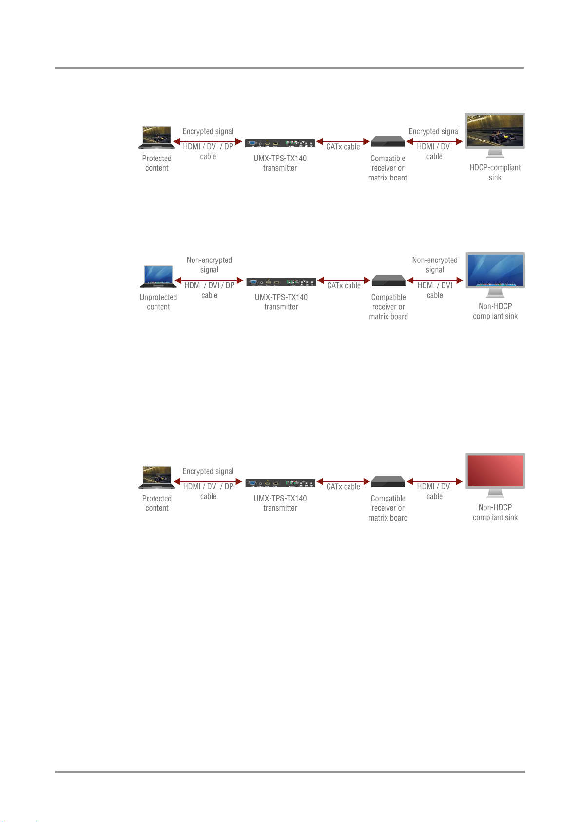
HDCP-compliant sink
Figure 3-2. HDCP-compliant sink
All the devices are HDCP-compliant, no manual setting is required, both protected and
unprotected content is transmitted and displayed on the sink.
Non-HDCP-compliant sink (HDMI/DVI) 1.
Figure 3-3. Non-HDCP compliant sink displaying unprotected content
Non-HDCP compliant sink is connected to the receiver. Some sources (e.g. computers)
always send HDCP encrypted signals if the receiver device reports HDCP compliancy,
however HDCP encryption is not required all the time (e.g. computer desktop image). If
HDCP is enabled in the transmitter, the image will not be displayed on the sink.
In the transmitter HDCP mode can be set to Auto. In this case, the transmitted signal will
not be encrypted if the content is not protected. Thus, non-HDCP compliant sinks will
display non-encrypted signal.
Non-HDCP-compliant sink (HDMI/DVI) 2.
Figure 3-4. Non-HDCP compliant sink and protected content
The layout is the same as in previous case: non-HDCP compliant display device is
connected to the receiver. Now the difference is that the content is protected, thus the
source is sending encrypted signal. In this case the extenders’ HDCP setting has no effect:
the source sends encrypted signal, since the content is protected. The display device will
show blank red, muted screen or pop up an error message that the sink is not HDCPcompliant. The solution is to replace the display device to a HDCP-capable one.
Section 3. Technologies Page 23 / 92
Page 24
4. Installation
4.1. Mounting
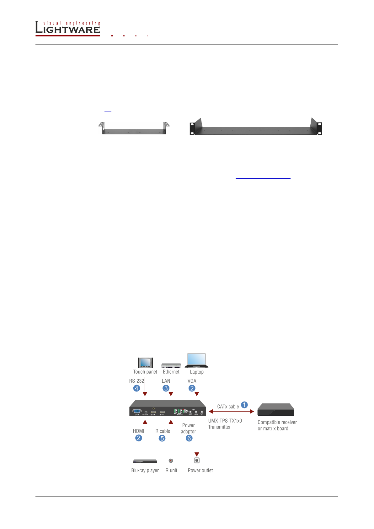
To mount the transmitter Lightware supplies optional accessories for different usage. There
are two kinds of mounting kits with similar fixing method. UMX-TPS-TX devices have two
mounting holes with inner thread on the bottom side; see the bottom view in section 9.1 on
page 86. Fasten the device by the screws enclosed to the accessory.
Figure 4-1. Under-desk double mounting kit and 1U high Rack shelf
The Under-desk double mounting kit makes easy to mount a single device on any flat
surface, e.g. furniture. 1U high rack shelf provides mounting holes for fastening two halfrack or four quarter-rack sized units. Pocket-sized devices can also be fastened on the
shelf. To order mounting accessories please contact [email protected].
Info: UMX-TPS-TX transmitters are half-rack sized.
4.2. Remote powering (PoE)
Remote powering of UMX-TPS-TX100 series was designed from a new approach as the
devices support PoE (Power over Ethernet). The transmitter can be powered remotely
through TPS connector by using an external power injector module anywhere on the
transmission lane. The transmitter is compatible with IEEE 802.3AF standard and able to
work as a Powered Device (PD) but cannot be used as a Power Sourcing Equipment
(PSE).
Important! UMX-TPS transmitters can receive the remote power only via their TPS output port. To use
Lightware’s remote power injector (TPS-PI-1P1) is highly recommended.
Info: If both remote and local power sources are connected to the device, the local one will be
used.
4.3. Connecting devices
Info: When a standard Ethernet device is connected to the TPS connector for some reason, the
transmitter is switched to Ethernet fallback mode automatically. TPS port is changed to
work as an Ethernet port, but to operate the transmitter this way is not recommended.
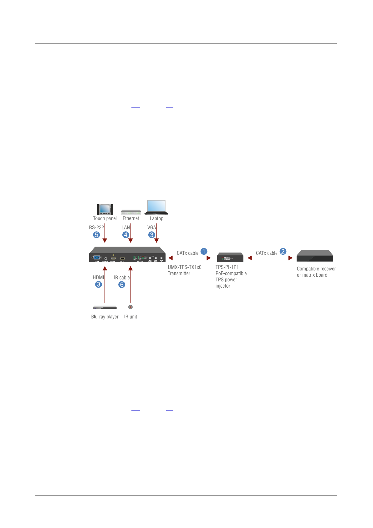
4.3.1. Connecting steps – using local PSU
Figure 4-2. UMX-TPS-TX1x0 – Powered by local adaptor
Page 24 / 92 Section 4. Installation
Page 25
UMX-TPS-TX100 series
User’s Manual
Step 1. Connect the transmitter and the receiver unit by a CATx cable via the TPS
connectors.
Step 2. Connect the desired video and audio source(s) to the input connector(s) of the
transmitter.
Step 3. Optionally connect the transmitter to a Local Area Network (LAN) in order to control
the device. More information about establishing the connection can be found in
section 6.4 on page 39.
Step 4. Optionally connect a serial device to the transmitter’s RS-232 port.
Step 5. Optionally for Infra-Red extension:
Connect the IR emitter to the IR OUT port of the transmitter.
Connect the IR detector to the IR IN port of the transmitter.
Step 6. Connect the power cord of the supplied adaptor to the transmitter or use
Lightware’s rack mountable power supply unit.
Step 7. Power on the devices.
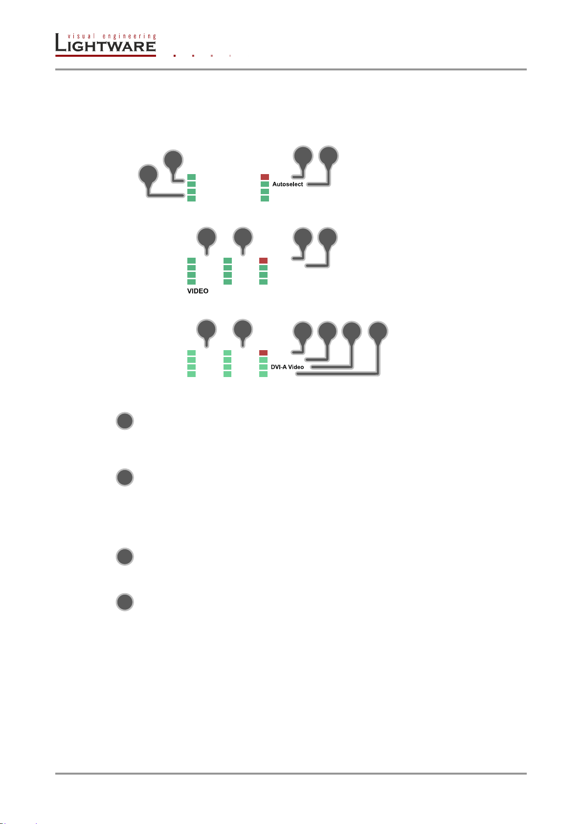
4.3.2. Connecting steps – using power injector (TPS-PI-1P1)
Step 1. Connect the “TPS OUT+PoE” port of the transmitter to the “TPS+PoE” output port
of TPS-PI-1P1 by a CATx cable.
Step 2. Connect the receiver (or the Matrix input board) to the power injector by a CATx
cable via the TPS connector.
Step 3. Connect the desired video and audio source(s) to the input connector(s) of the
transmitter.
Step 4. Optionally connect the transmitter to a Local Area Network (LAN) in order to control
the device. More information about establishing the connection can be found in
section 6.4 on page 39.
Step 5. Optionally connect a serial device to the transmitter’s RS-232 port.
Step 6. Optionally for Infra-Red extension:
Connect the IR emitter to the IR OUT port of the transmitter.
Connect the IR detector to the IR IN port of the transmitter.
Step 7. Power on the devices.
Figure 4-3. UMX-TPS-TX100 series – Powered over Ethernet
Section 4. Installation Page 25 / 92
Page 26
5. Front panel operations
HDCP
HDMI AUDIO
AUDIO
HDMI VIDEO
VGA VIDEO
1
2
3
4
AUDIO
Autoselect
HDCP
DVI-D
DVI-A
DVI-D
HDMI HDMI
VGA Audio
3 1 2
4
Autoselect
HDCP
Audio2DVI-D
DP
DVI-D
DP
HDMI HDMI
VGA Audio1
VIDEO AUDIO
3 1 2
4
1 2
1
2
3
4
5.1. Front panel LEDs
UMX-TPS-TX120
UMX-TPS-TX130
UMX-TPS-TX140
Legend for front panel LEDs
Video sources
- dark: video source is not selected
- blinks: video source is selected but not active
- lights: video source is selected and the port is active
Audio sources
- dark: audio source is not selected
- blinks: the audio source is selected but not active, regardless of the output mode
- lights: (with short pause): audio source is selected and the port is active
(continuously): audio source is selected, active and the audio is embedded
to the output video stream
HDCP
dark: video output signal is not encrypted with HDCP
lights: video output signal is encrypted with HDCP
AUTOSELECT
dark: autoselect function is OFF
blinks: searching for signal (the video LEDs also blink)
lights: active video signal was found (the selected video LED also lights)
Info: A port is active if there is a valid signal on it.
Firmware indication
After being powered on, the transmitter lights up all LEDs, than displays its firmware
version using three LEDs on the front panel: the upper three in the left column.
The top LED means the first number of the firmware version – actually this is the
main version. From the top the second and the third LEDs mean the second and the
third numbers of the firmware version which mean the subversions.
Page 26 / 92 Section 5. Front panel operations
Page 27
LIVE
SRVC
LINK
1
2
3 4
1
2
3
4
5.2. Rear panel LEDs
Legend for rear panel LEDs
LIVE
dark: device is not powered
blinks: (slow): device is powered and operational
(fast): device is in bootload mode
lights: device is powered but no operation
RS-232
dark: RS-232 ports (Local and Link) are in Pass-through mode
blinks: command injection mode is active
lights: RS-232 ports (Local and Link) are in Control mode
SRVC reserved
UMX-TPS-TX100 series
User’s Manual
LINK
dark: no TPS link between transmitter and receiver
blinks: (slow): low power mode is active
(fast): Ethernet fallback mode is active
lights: TPS link is established, HDBaseT or Long Reach mode is active
Info: See more information about TPS link modes in section 6.6.6 on page 44.
Info: LEDs of Ethernet connectors are described in section 2.5.5 on page 18.
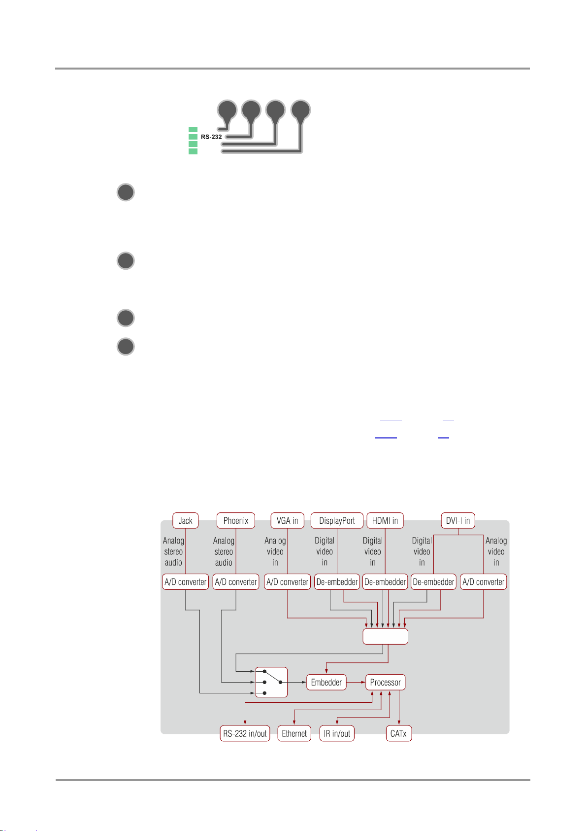
5.3. Input port selection
UMX-TPS-TX transmitters accept many video and audio input signals depend on the
model’s capabilities. Only one video and audio can be selected to transmit; below figure
shows the block diagram of input/output selection.
Figure 5-1. Input port selection – summary
Section 5. Front panel operations Page 27 / 92
Page 28
UMX-TPS-TX120
UMX-TPS-TX130
UMX-TPS-TX140
Audio source
HDMI
DP
DVI-D
Audio1
(or Audio)
Audio2
Video
source
HDMI -
-
DP
- -
VGA - -
-
DVI-D - -
DVI-A - -
-
VGA
HDMI
Autoselect
VGA
HDMI
DVI-D
DVI-A
Autoselect
VGA
HDMI
DP
DVI-D
DVI-A
Autoselect
The audio/video input can be selected by any of the following ways:
Pressing the Audio select / Video select button,
Using the Autoselect function,
Using Lightware Device Controller,
Sending LW2 or LW3 protocol command.
The transmitter can receive LW2 or LW3 command through Ethernet or RS-232 interface,
which can be either local or remote. It means that the input selection can also be controlled
remotely from a TPS receiver’s RS-232 or Ethernet port.
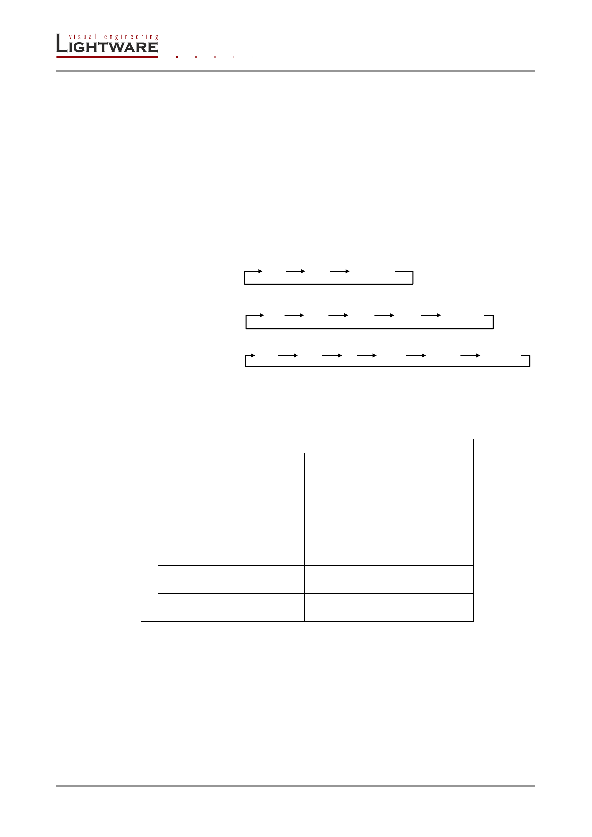
Direct selection (video input port)
Desired video input can be selected by the Video select button from front panel. The
selection order of the inputs depend on the model as follows:
5.3.1. Audio embedding – allowed connections
Selected audio signal can be embedded to an input video signal; following table contains
the allowed connections:
Info: If 4K video is selected to the output, analog audio cannot be embedded to the video stream
due to the capabilities of the video IC, thus the original audio stream will be transmitted.
Figure 5-2. Cross audio-embedding support
Page 28 / 92 Section 5. Front panel operations
Page 29
UMX-TPS-TX100 series
Event
Selected port still
has a valid signal?
Remains active
Y
N
Port with priority 0
has a valid signal?
Port with priority 0 is
selected
Y
N
Port with priority 1
has a valid signal?
Port with priority 1 is
selected
Y
N
Port with priority 2
has a valid signal?
Port with priority 2 is
selected
Y
N
Port with priority 3
has a valid signal?
Port with priority 3 is
selected
Y
N
Port with priority 4
has a valid signal?
Port with priority 4 is
selected
Y
N
Port with priority 5
has a valid signal?
Port with priority 5 is
selected
Y
N
crosspoint setting
Don’t change
Disconnect the input
port from the output
Disconnect
User’s Manual
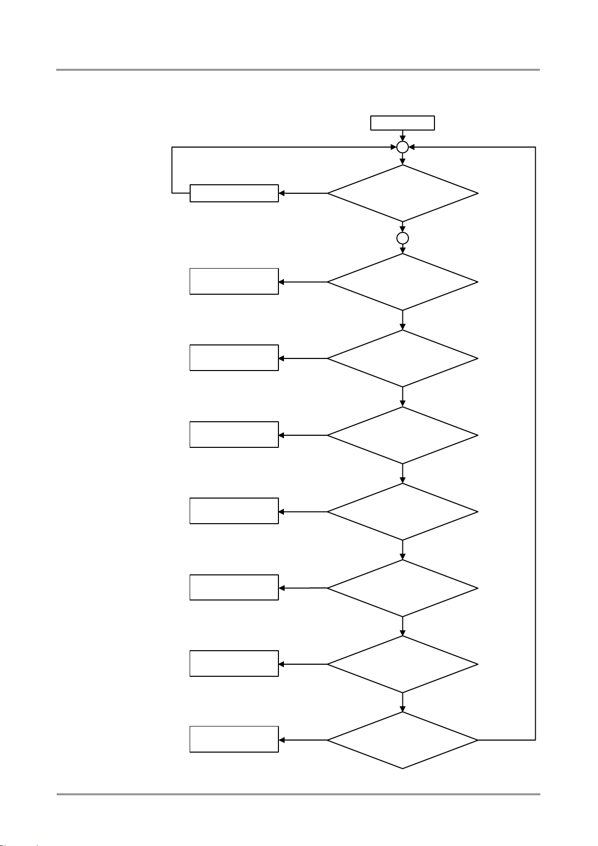
5.3.2. Autoselect – First detect mode
Meaning: Selected input port is switched to the output while it has an active signal.
Section 5. Front panel operations Page 29 / 92
Autoselect
Figure 5-3. Autoselect – First detect mode
Page 30

Priority
0 1 2 3 4
31
Input port
P3
DP
P2
HDMI
P4
DVI-D
P1
VGA
P5
DVI-A
Test pattern
Info: For analog audio inputs the signal detection is handled on a different way. If the 3.5 mm
jack is connected to Audio/Audio 1, the port is handled as it has an active signal; while
Audio 2 (Phoenix) is always handled as it has an active signal.
Example (Video input ports on a UMX-TPS-TX140)
The priority values have to be assigned to each input port which are desired to use. As an
example the followings priority settings will be used when explaining an example to this
mode:
In this case lowest priority (31) is assigned to the Test pattern thus cannot be selected.
After an event the device always checks the selected port. If there is a valid signal on it,
the port remains selected. If there is no valid signal on the port the device checks the port
with priority 0, in this case P3 (DP). If there is a valid signal on that port, it remains selected.
If there is no valid signal on that port the device checks the port with priority 1, P2 (HDMI).
If there is a valid signal on that port, it remains selected. If there is no valid signal on that
port the device checks the port with priority 2, P4 (DVI-D). If there is a valid signal on that
port, it remains selected. If there is no valid signal on that port the device checks the port
with priority 3, P1 (VGA). If there is a valid signal on that port, it remains selected. If there
is no valid signal on that port the device checks the port with priority 4, P5 (DVI-A). If there
is a valid signal on that port, it remains selected. If there is no valid signal on that port the
device checks the Autoselect crosspoint setting. If the setting is “no change”, then the
crosspoint remain unchanged and the process starts from the very beginning. If the
Autoselect crosspoint setting is “disconnect”, then no video input port will be selected to
the output.
Autoselect priority and crosspoint settings can be changed via the LDC surface, see section
6.6.6 on page 44, or by protocol commands.
Special features
If more than one input port is active (there is valid signal on the input port) when the device
is powered on, the priority order will be used to select the input port.
Page 30 / 92 Section 5. Front panel operations
Page 31
UMX-TPS-TX100 series
Event
Port with
priority 0 has a
valid signal?
Port with priority 0
is selected
Y
N
Port with
priority 1 has a
valid signal?
Y
N
Port with
priority 2 has a
valid signal?
Y
N
Port with
priority 3 has a
valid signal?
Y
N
Port with
priority 4 has a
valid signal?
Y
N
Port with
priority 5 has a
valid signal?
Y
N
Port with priority 1
is selected
Port with priority 2
is selected
Port with priority 3
is selected
Port with priority 4
is selected
Port with priority 5
is selected
User’s Manual
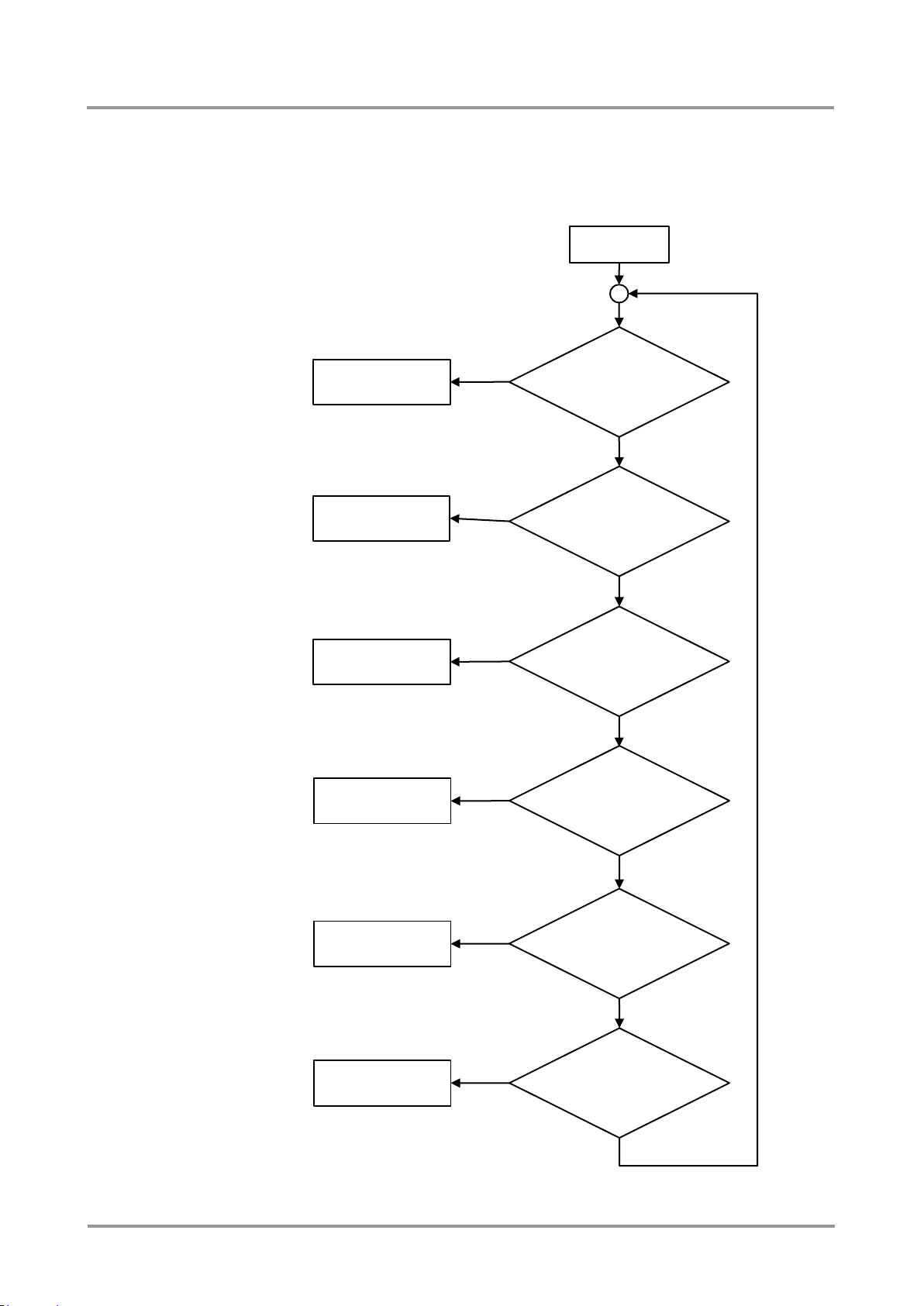
5.3.3. Autoselect – Priority detect mode
Meaning: The highest priority active input will be selected to transmit.
The auto selection priority is arbitrary configurable. We can make any combination of the
ports for priority. We call the input port active if there is a valid signal on it.
Section 5. Front panel operations Page 31 / 92
Figure 5-4. Autoselect – Priority detect mode
Page 32

Priority
0 1 2 3 4
5
Input port
P3
DP
P2
HDMI
P4
DVI-D
P1
VGA
P5
DVI-A
P6
Test pattern
Info: For analog audio inputs the signal detection is handled on a different way. If the 3.5 mm
jack is connected to Audio/Audio 1, the port is handled as it has an active signal; while
Audio 2 (Phoenix) is always handled as it has an active signal.
Example (video input ports on a UMX-TPS-TX140)
The priority values have to be assigned to each input port which are desired to use. As an
example the followings priority settings will be used when explaining an example to this
mode:
After an event the device always checks the port with the highest priority, P3 (DP). If there
is a valid signal on it, P3 will be selected. If there is no valid signal on DP input port the
device checks the following port with priority 1, P2 (HDMI). If there is a valid signal on it,
P2 will be selected. If there is no valid signal on HDMI input port the device checks the
following port with priority 2, P4 (DVI-D). If there is a valid signal on it, P4 will be selected.
If there is no valid signal on DVI-D input port the device checks the following port with
priority 3, P1 (VGA). If there is a valid signal on it, P1 will be selected. If there is no valid
signal on VGA input port the device checks the following port with priority 4, P5 (DVI-A). If
there is a valid signal on it, P5 will be selected. If there is no valid signal on DVI-A input
port P6 port (Test pattern) will be selected.
In this case if there is no valid video on the input ports, “Test pattern” will be selected to the
output until there is a valid signal on any input port.
Port priority settings
Autoselect priority settings can be changed via the LDC surface, see section 6.6.6 on page
44, or by protocol commands.
Special features
The same priority number can be set to different input ports. In this case the input port with
the lowest port number will have the highest priority among them. E.g. set the priority of P2
(HDMI) and P3 (DP) to “0”, thus the HDMI input port will have higher priority since P2 is
lower than P3.
Nevertheless input ports can be skipped from the priority list by giving them the lowest
value: priority 31.
5.4. IR interface
IR receiver can sense IR light (e.g. emitted by a remote controller) and send electrical
signals to the IR transmitter. The transmitter unit processes the electrical signals and emits
IR light toward the controlled device (e.g. projector). This is a simplex communication
between the IR receiver and IR transmitter, so IR OUT receptacle accepts only the IR
transmitter and IR IN receptacle accepts only the IR receiver. IR accessories are not
interchangeable.
IR signal from the IR input is transmitted to the receiver or input board and vica versa.
Info: Direct line of sight is required between IR transmitter and the controlled device (e.g. Blu-
Ray or DVD player) and the same is valid for the IR receiver and the controller device (e.g.
remote controller).
Info: If Low power mode is active and the Ethernet connector is plugged/unplugged, minor
temporary disturbance may arise in the transmission of RS-232 and/or IR signal.
Page 32 / 92 Section 5. Front panel operations
Page 33

5.5. RS-232 modes
The device has RS-232 interface that supports two modes:
RS-232 PASS mode: the incoming data from the local and link sides passed
through to the other side without processing it.
RS-232 CONTROL mode: the incoming data from both sides processed and
interpreted as LW2 or LW3 protocol commands. Selecting the control protocol
(LW2 or LW3) on the RS-232 interface can be done either by using Lightware
Device Controller or sending LW2/LW3 protocol commands. The interface can be
set for the Local and Link RS-232 line independently from each other.
Serial communication diagram (example)
UMX-TPS-TX100 series
User’s Manual
The Controller and the Controlled devices are connected via RS-232, the extenders are
connected via the TPS connectors by CATx cable. Serial communication requires to have
the proper settings: BAUD rate, databits, stopbits and parity in all devices.
E.g. it is possible the control the device with LW2 commands on the local RS-232 interface,
and with LW3 commands remotely on the link RS-232 interface. In this mode, the local side
and the link side are not connected.
ROT v2
The device can also be controlled through ROT v2 (RS-232 over TPS) which means
RS-232 mode can be changed by protocol commands. ROT only supports few commands,
which answer length is less than 50 bytes.
Info: If Low power mode is active and the Ethernet connector is plugged/unplugged, minor
temporary disturbance may arise in the transmission of RS-232 and/or IR signal.
5.5.1. Control mode
In Control mode the transmitter’s CPU can receive commands and send responses to/from
its own serial port or to/from the serial port on the receiver through the CATx (TPS) cable.
Figure 5-5. UMX-TPS-TX100 series transmitter in control mode
Section 5. Front panel operations Page 33 / 92
Page 34

5.5.2. Pass-through mode
In pass-through mode the serial connectors on the transmitter and on the receiver are
linked together through the CATx (TPS) cable. This allows direct communication between
a device connected to the receiver unit and a device connected to the transmitter unit.
Figure 5-6. UMX-TPS-TX100 series transmitter in pass-through mode
5.6. General purpose input/output ports (only on UMX-TPS-TX140)
The device has 7 GPIO pins, which operates at TTL digital signal levels and can be
controlled with both LDC and LW2 / LW3 protocol commands.
Output pin state can be set with specific command.
Input pin state can be queried, and a notification is sent from the device, if the state
is changed.
As a special function, the GPIO pins would act the same way as video select, audio select
and show me buttons.
As another special function a video input can be selected by a GPIO pin, e.g. if GPIO1
input is activated, VGA connector becomes the active input.
5.7. Special functions
5.7.1. Control lock
Press the Audio select and Show Me buttons together (between 100 ms) to disable/enable
front panel buttons; front panel LEDs blink 4 times when locking/unlocking.
If the control lock is enabled and a button is pressed, front panel LEDs blink 3 times.
5.7.2. Reset to factory default settings
If factory default values have to be restored, do the following steps:
Step 1. Make sure the device is powered on and operational (control is not locked).
Step 2. Press and keep pressed the Show me button for 10 seconds.
Step 3. After 5 seconds front panel LEDs start blinking but keep on pressing the button.
Step 4. After 10 seconds the blinking gets faster; release the button and press it 3 times
again quickly (within 3 seconds).
Step 5. The LEDs get dark, the device restores the factory default settings and the device
reboots.
Factory default settings are listed in section 9.3 on page 87.
Page 34 / 92 Section 5. Front panel operations
Page 35

UMX-TPS-TX100 series
User’s Manual
5.7.3. Enable DHCP IP address
The device gets a fix IP address as a factory default setting. If this setting does not fit to
the circumstances during install or usage, the IP address setting can be modified from the
front panel by enabling DHCP server:
Step 1. Make sure the device is powered on and operational (control is not locked).
Step 2. Press and keep pressed the Show me button for 5 seconds.
Step 3. After 5 seconds front panel LEDs start blinking; release the button and press it 3
times again quickly (within 3 seconds).
Step 4. The LEDs get dark, DHCP gets enabled and the device reboots.
5.7.4. Entering bootload mode
It may happen that the firmware upgrade process is not successful as the device cannot
be switched to bootload mode automatically. In this case transmitter device can be forced
to switch to bootload mode as follows:
Step 1. Make sure the transmitter is powered off.
Step 2. Press and keep pressed the Show me button.
Step 3. Power on the transmitter. If the device is switched to bootload mode the LIVE LED
is blinking quickly (less than 500 ms duty). The other LEDs are off.
Device can be switched to normal operation mode by resetting or switching it off and on
again.
Section 5. Front panel operations Page 35 / 92
Page 36
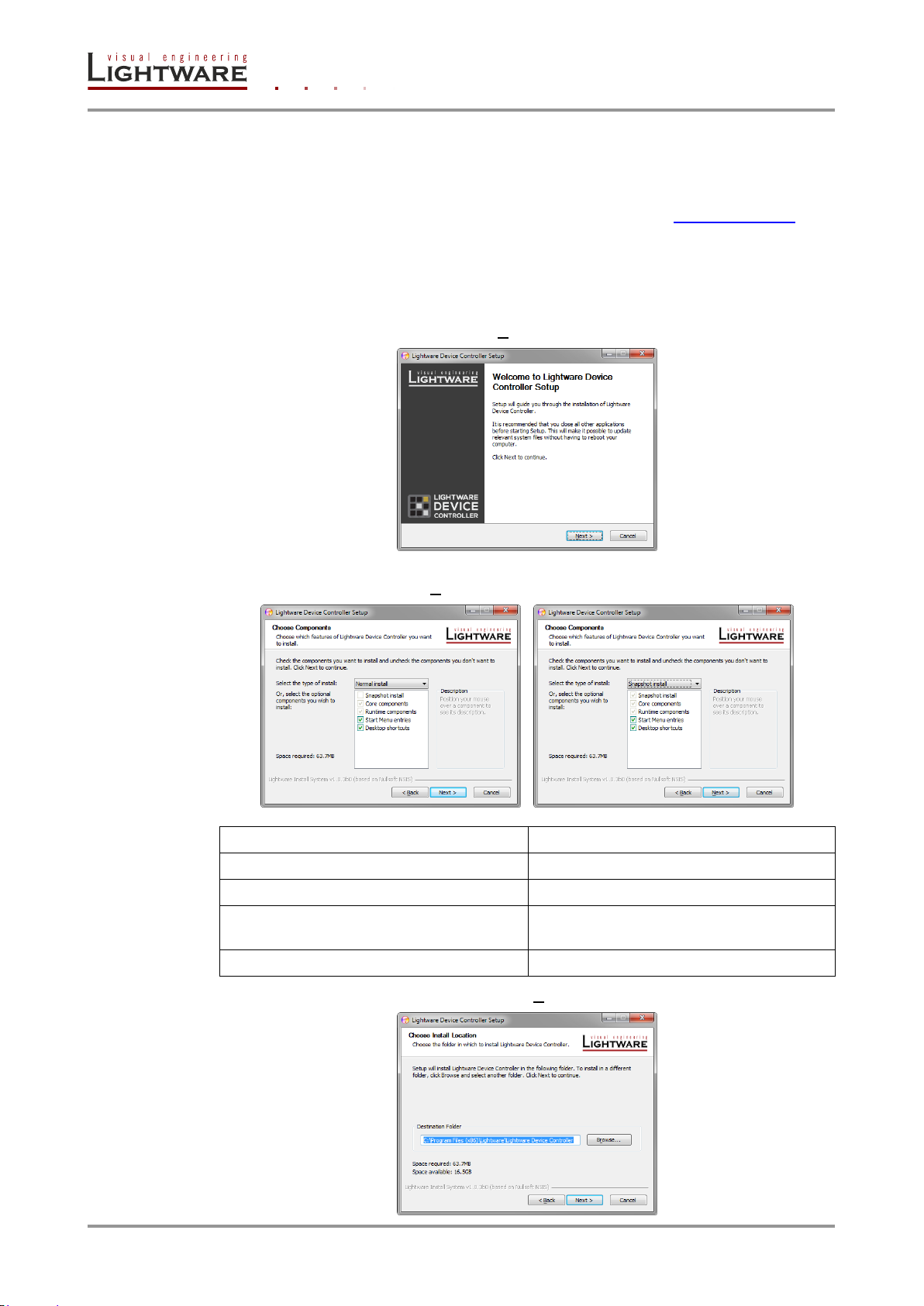
Normal install
Snapshot install
Available for Windows and MAC OS X
Available for Windows
The installer can update only this instance
Cannot be updated
Only one updateable instance can exist for
all users
More than one different version can be
installed for all users
Does not contain the version in its name
Version number is displayed in the name
6. Software control – using Lightware Device Controller (LDC)
The device can be controlled by a computer through the Ethernet port using Lightware
Device Controller. The software can be installed to a Windows PC or MAC OS X. The
application and the User’s manual can be downloaded from www.lightware.eu. The
Windows and the Mac versions have the same look and functionality.
6.1. Steps of the installation in case of Windows OS
Step 1. Run Install_LDC_v1.1.0b3.exe. If User Account Control appears click Yes.
Step 2. A welcome window opens. Click Next.
Step 3. Select the type of the installation: normal or snapshot install. Select the optional
components then click Next. (Normal install is recommended.)
Step 4. Select the destination folder and click Next. (Default path is highly recommended.)
Page 36 / 92 Section 6. Software control – using Lightware Device Controller (LDC)
Page 37
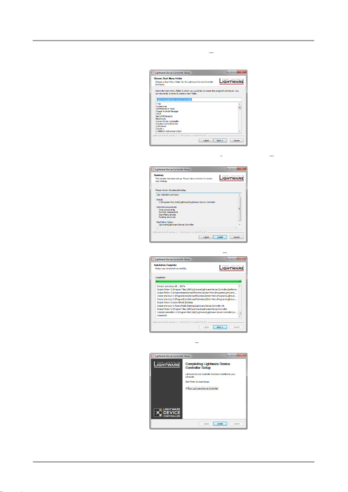
UMX-TPS-TX100 series
User’s Manual
Step 5. Select the Start Menu Folder and click Next. (Using the default folder is highly
recommended. If the Start menu entries was not checked in Step 3 this window will
be skipped.)
Step 6. Verify the settings and if they are correct click Install. (If not, click Back and change
the setting.)
Step 7. After the installation of the last component the Next button is activated. Click on it.
Step 8. If the installation is complete, click Finish. (Uncheck the box if the running of the
LDC will be delayed.)
Section 6. Software control – using Lightware Device Controller (LDC) Page 37 / 92
Page 38
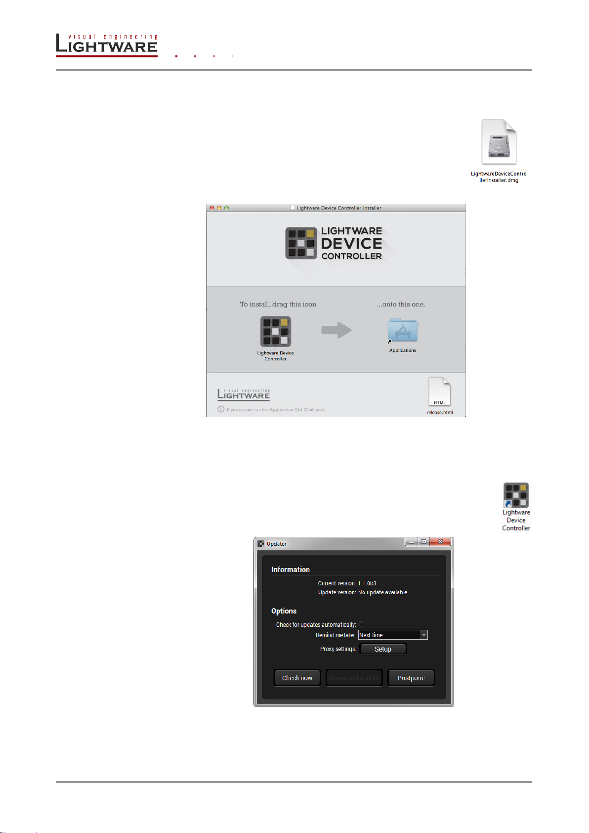
6.2. Steps of the installation in case of Mac OS X
Info: After the installation the Windows and the Mac application has the same looks and
functionality.
Step 1. Mount the DMG file with double clicking on it.
Step 2. Drag the LDC icon over the Applications icon to copy the program
into the Applications folder. If you want to copy the LDC into
another location just drag the icon over the desired folder.
Info: This type of the installer is equal with the Normal install in case of Windows. This is an
updateable version with the same attributes.
6.3. LDC Upgrade
Step 1. Run the application.
The Device Discovery window appears automatically and the program
checks the available updates on Lightware’s website and opens the
update window if the LDC found updates.
The current and the update version number can be seen in the top of the window
and they are shown in this window even with the snapshot install.
Page 38 / 92 Section 6. Software control – using Lightware Device Controller (LDC)
Page 39
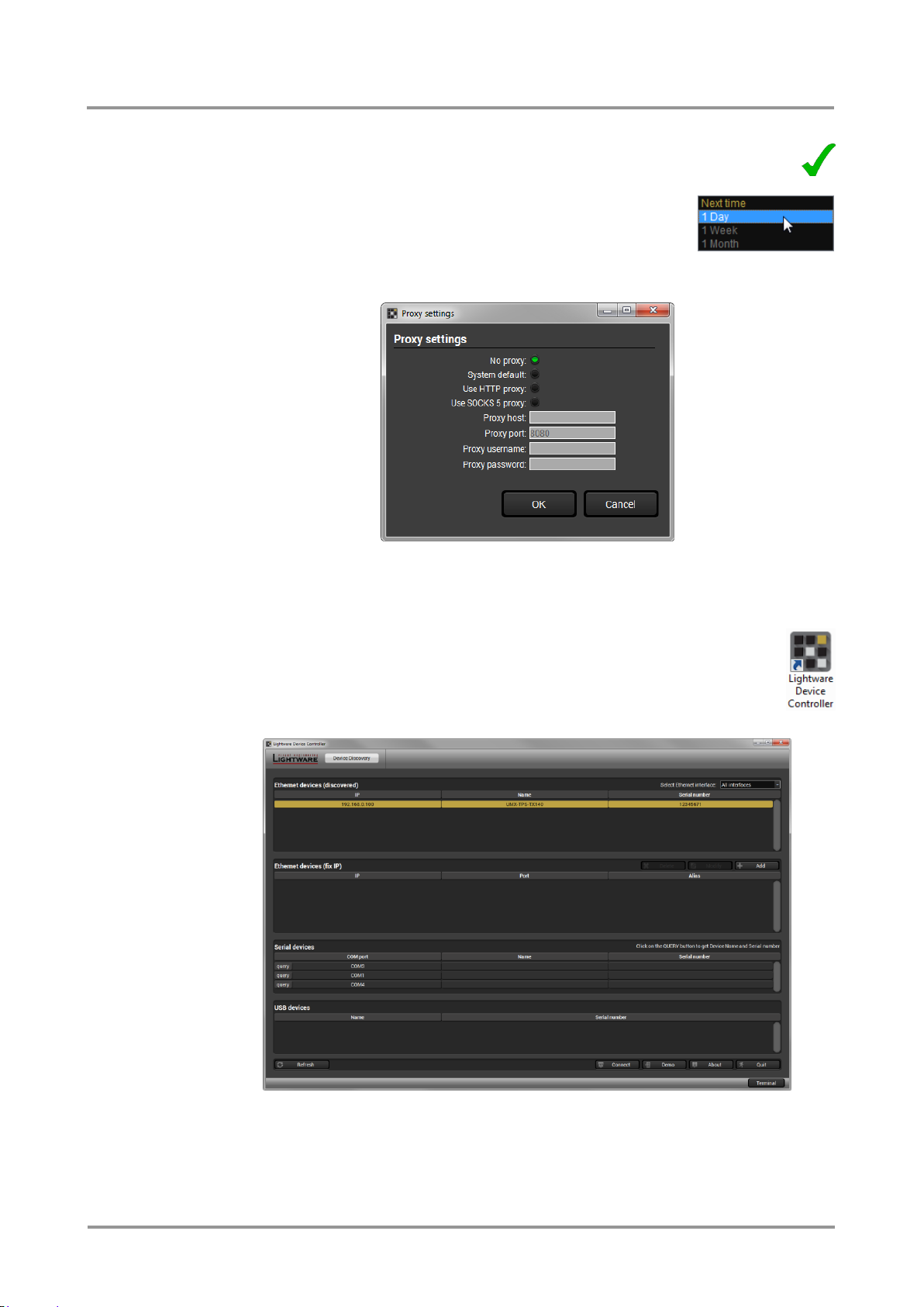
UMX-TPS-TX100 series
User’s Manual
Step 2. Set the desired update setting in the option section.
a) If you do not want to check the update automatically, uncheck the
circle, which contains the green tick.
b) If the postponing is the desired choice for the
updating, the reminder can be set for different
duration with the drop-down list.
c) If the proxy settings traverse the update process, set the proper values
then click the OK button.
Step 3. Click the Download update button to start the upgrading.
User can check updates manually by clicking the Check now button.
6.4. Establishing the connection
Step 1. Connect to the device by a computer directly or via Ethernet. Cable type
does not matter, both patch and cross cable can be used.
Step 2. Run the controller software; device discovery window appears
automatically.
Figure 6-1. Ethernet connection in Device discovery window
Step 3. Select the desired device and click on the Connect button.
Section 6. Software control – using Lightware Device Controller (LDC) Page 39 / 92
Page 40
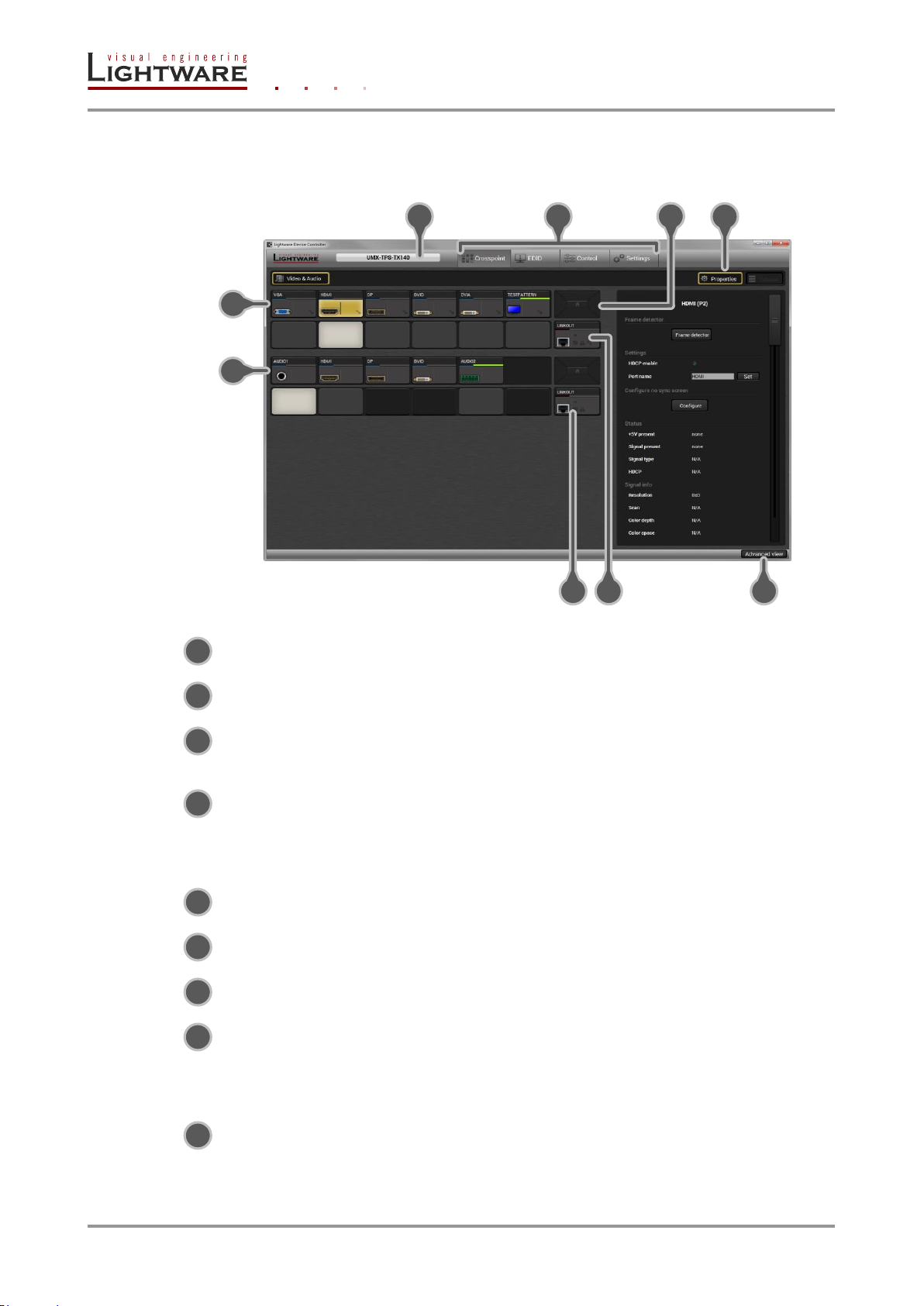
6.5. Crosspoint menu
2
3
4
1
5
6
9
7
8
1
2
3
4
5
6
7
9
8
When LDC finds the hardware, it determines the product type, and the LDC starts with the
default page, showing the Crosspoint menu.
Main menu The available menu items are displayed. The active one is
showed with dark grey background color.
Information ribbon The label shows the type of the connected device. Device
discovery window can be displayed by clicking on this ribbon.
Video input ports Each tile represents a video input port. The tile below the port
shows current crosspoint setting; if the port is switched to the
output, the color of the tile is white, otherwise grey.
Audio input ports Each tile represents an audio input port. The tile below the
port shows current crosspoint setting; if the port is switched to
the output, the color of the tile is white, otherwise grey. Dark
grey means the audio port is not allowed to embed in the
current video input port.
Audio output (TPS) The audio output of the TPS output.
Video output (TPS) The video output of the TPS output.
Advanced view Displaying Advanced view page, showing the Terminal
window and the protocol tree.
Navigation buttons If the window is smaller than required, the ports may not fit in
the available area. Thus the arrows on this button get
activated and the ports can be scrolled. Clicking on the middle
icon restores the original layout (window is arranged to the left
top corner).
Properties Toggling right panel display, showing the properties of
Page 40 / 92 Section 6. Software control – using Lightware Device Controller (LDC)
selected port. The panel is also displayed when clicking on a
port tile.
Page 41
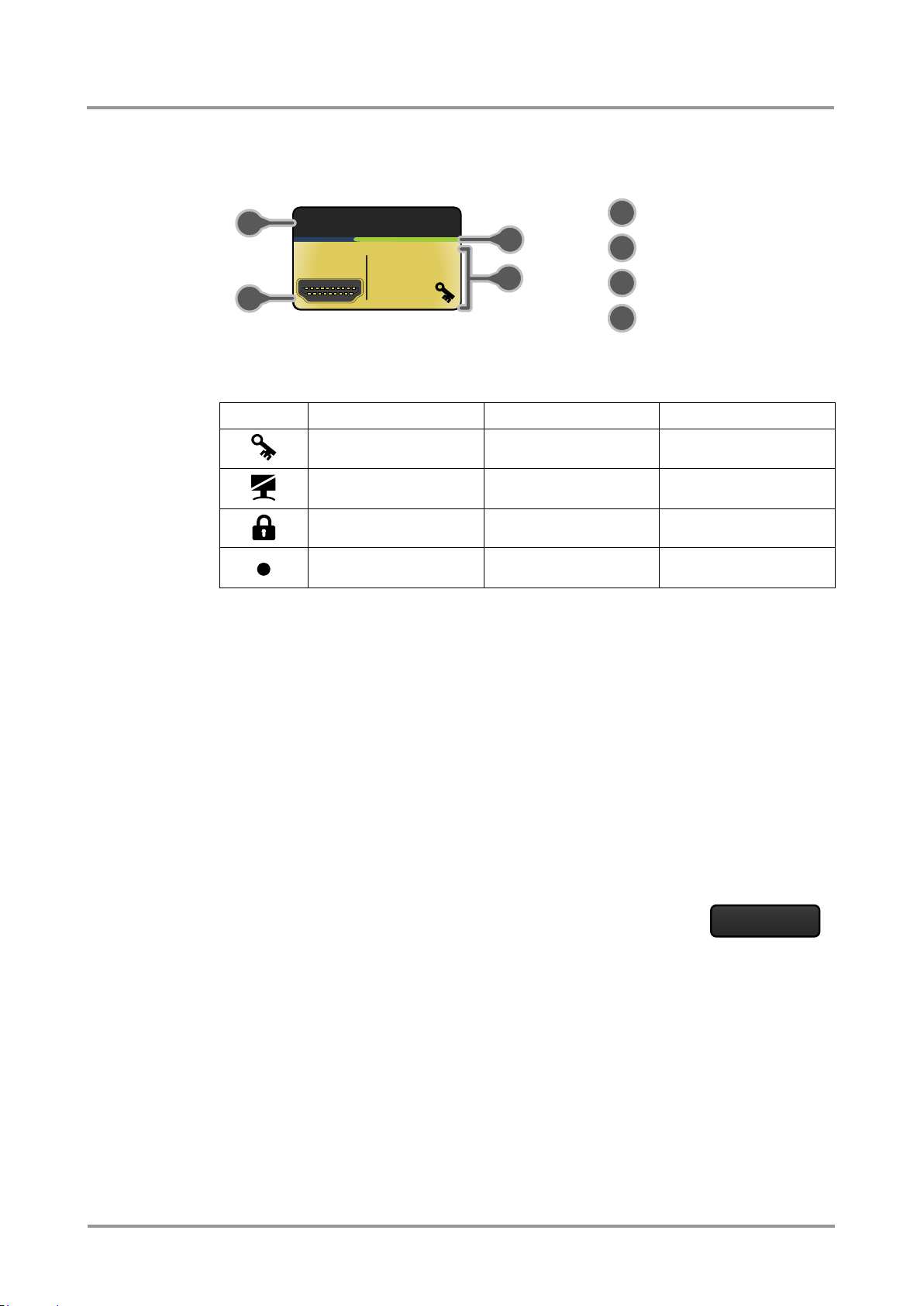
UMX-TPS-TX100 series
Port name
Port icon
State indicators
Signal present (green),
not present (grey)
Icon
Icon is not displayed
Icon is grey
Icon is black
HDCP is not supported
Signal is not encrypted
with HDCP
Signal is encrypted
with HDCP
-
Port is unmuted
Port is muted
-
Port is unlocked
Port is locked
-
Autoselect is disabled
Autoselect is enabled*
HDMI
2
3 4 1 1
2 3 4
Frame detector
User’s Manual
Port tiles
The colors of the port tiles and the displayed icons represent different states and
information:
State indicators
Following icons display different states of the port/signal:
* When Autoselect is enabled the icon is displayed in green.
6.6. Port properties and settings
Left click on Properties button to display the properties panel of selected port. Signal status
information and the most important parameters are displayed on the panel. Special
functions (e.g. frame detector, port naming) are also available on the panel.
Port name
The name of a port can be changed by typing the new name and clicking the Set button.
The following characters are allowed when naming:
Letters (A-Z) and (a-z), hyphen (-), underscore (_), numbers (0-9) and dot (.).
6.6.1. Frame detector (on video input ports)
Input ports can show detailed information about the signal like blanking intervals and active
video resolution. This feature is a good troubleshooter if compatibility
problems occur during system installation. To access this function,
open Properties panel of the input port on which the signal has to be
checked. Click on Frame Detector button to show detailed timings.
Section 6. Software control – using Lightware Device Controller (LDC) Page 41 / 92
Page 42
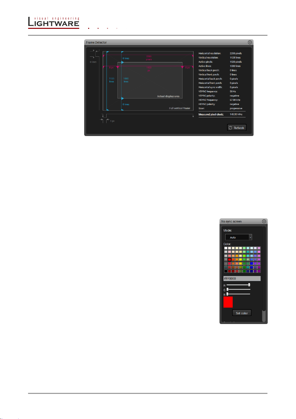
Figure 6-2. Frame detector window
Lightware’s frame detector function works like an input signal analyzer and makes possible
to determine the exact video format that is sent by the source, thus helps to identify many
problems. E.g. actual timing parameters may differ from the expected and this may cause
some displays to drop the picture.
Frame detector measures detailed timings on the matrices’ incoming video signals just like
a built-in oscilloscope, but it is much more easy to use. Actual display area shows the active
video size (light grey). Dark gray area of the full frame is the blanking interval which can
contain the info frames and embedded audio data for HDMI signals. Shown values are
measured actually on the signal and not retrieved only from the HDMI info frames.
6.6.2. No sync screen
The port generates an image which can be displayed when there
is no incoming signal on the port. Each port can have individual
settings:
Mode: Auto – no sync screen is displayed when
Always on – no sync screen is displayed
Always off – no image is displayed when
Color: Set the desired color and press the Set color
Resolution: Set the desired image resolution from the
there is no incoming signal
always, independently from the incoming
signal
there is no incoming signal
button to store.
drop-down menu.
Page 42 / 92 Section 6. Software control – using Lightware Device Controller (LDC)
Page 43
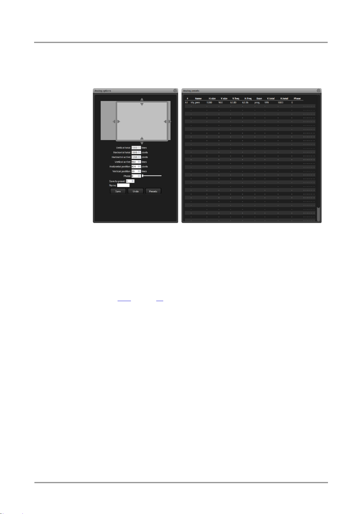
UMX-TPS-TX100 series
User’s Manual
6.6.3. VGA and DVI-A video input port properties
Analog options
Analog video signals are digitized on the input. The timing parameters can be adjusted
here if needed. Timing presets can be saved for each resolution separately.
Presets can be named and saved, nevertheless the preset list can be saved to a file and
loaded at any time.
Settings
Besides the port name, the source mode can be set: Auto, RGB or YUV.
6.6.4. TESTPATTERN properties
The TESTPATTERN can also be selected as an input port, which is a solid image with
user-defined color and resolution. The settings are the same as for “No sync screen”, see
the section 6.6.2 on page 42.
6.6.5. Analog audio port properties (Audio, Audio1 and Audio 2)
Certain parameters of analog audio input signal can be adjusted as follows:
Volume:
from 0 dB to -52 dB (step 0.25 dB), from -54 dB to -66 dB (step
2 dB); -69 dB; -72 dB; -78 dB (default is 0 dB)
Balance:
from 0 to 100, step 1 (default is 50 = center)
Section 6. Software control – using Lightware Device Controller (LDC) Page 43 / 92
Page 44
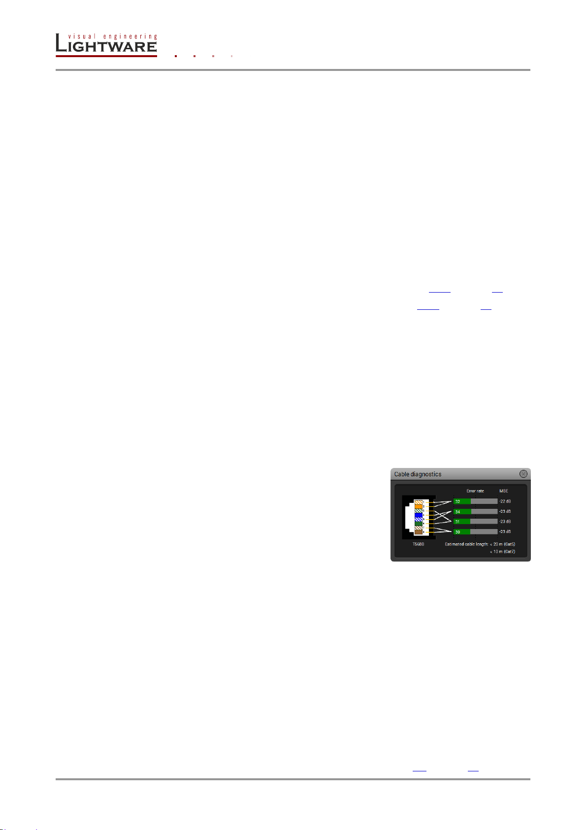
6.6.6. TPS output port properties and mode settings
Muting/Locking
TPS output can be easily muted by clicking on the button Unmuted. If the output is muted,
button text is Muted. When the port is muted, no signal is present on the output.
TPS output can be easily locked by clicking on the button Unlocked. If the output is locked,
button text is Locked. If the port is locked, its mute state cannot be changed neither by the
button, nor by loading a preset.
Autoselect
The autoselect feature can be easily set via the TPS OUT properties panel. The Autoselect
section contains the following settings:
Settings
Enabled: The Autoselect mode is ON.
Disabled: The Autoselect mode is OFF.
Priority detects: Priority detect mode is active (see section 5.3.3 on page 31).
First detect: First detect mode is active (see section 5.3.2 on page 29).
Don’t change: If there is no incoming signal, there is no change in the crosspoint.
Disconnect: If there is no incoming signal, selected input is disconnected from
the output.
Always press the Set button after the modification to store the settings.
Input priorities
The available input ports are listed; each one has its own priority number (equal numbers
are allowed). If you want to disable a port from the priority list, uncheck the setting next to
the priority number and the priority number will be emptied and disabled. Smaller number
means higher priority as usual.
Always press the Set priorities button after the modification to store the settings.
Cable diagnostics (only on TPS Video output port)
The estimated cable length and the quality of the link are
measured periodically and the diagnostic window shows
the values in real-time. If the green bars hit the first line
in the middle they turn into red. It means the number of
the errors – during the extension – is higher than the
recommended one. The link might be alive but
recovering of the received data is not guaranteed.
Info: Each bar represents a differential line in the CATx cable. The inappropriate termination of
the cable usually occurs high error rates. Check the cable terminations or change the cable.
TPS settings (only on TPS Video output port)
Basic transmission parameters can be set on this panel as follows:
TPS mode
Auto: The TPS mode is determined automatically
HDBaseT: Ideal for high resolution signals up to 4K but with shorter cable
Longreach: Ideal for big distances, but until 1080p
Only RS232: Only RS-232 communication is transmitted (Low Power
mode)
Only RS232 + Eth: Only RS-232 and Ethernet communication is transmitted (Low
power mode)
Info: The allowed cable lengths and resolutions are listed in section 9.2 on page 87.
Page 44 / 92 Section 6. Software control – using Lightware Device Controller (LDC)
Page 45
UMX-TPS-TX100 series
Mode selected on RX side
RS232
RS232+Eth.
HDBaseT
Longreach
Auto
Mode
selected on TX
side
RS232
RS232
RS232
RS232
RS232
RS232
RS232+Eth.
RS232
RS232+Eth.
RS232+Eth.
RS232+Eth.
RS232+Eth.
HDBaseT
RS232
RS232+Eth.
HDBaseT
RS232
HDBaseT
Longreach
RS232
RS232+Eth.
RS232
Longreach
Longreach
Auto
RS232
RS232+Eth.
HDBaseT
Longreach
Auto
User’s Manual
These settings refer to the transmitter. The TPS transmission mode between the transmitter
and the receiver depends on the settings of both units. The table below details the system's
state with regard to mode selection behavior for all possible combinations in both ends of
the link:
Figure 6-3. TPS mode determination between transmitter and receiver
Info: When a standard Ethernet device is connected to the TPS connector for some reason, the
transmitter is switched to Ethernet fallback mode automatically. TPS port is changed to
work as an Ethernet port, but to operate the transmitter this way is not recommended.
Info: If Low power mode is active and the Ethernet connector is plugged/unplugged, minor
temporary disturbance may arise in the transmission of RS-232 and/or IR signal.
When using automatic operation mode selection, the device uses built-in sensors to
determine the mode of operation. If the transmitter and the receiver is in Auto mode, the
source side is the initiator. It will negotiate each state transition with its sink side partner.
When one of the devices is configured to manual operation mode selection, the other
device may be placed in automatic mode. In this case, the mode transition negotiation is
initiated by the host-managed device and the auto-mode device follows through.
HDMI mode
Auto: The output video signal (DVI or HDMI) is determined automatically
DVI: The output video signal is DVI (no audio is transmitted)
HDMI: The output video signal is HDMI (with 24 / 30 / 36 bit)
Color space
Auto: The color space of the output video signal is determined automatically
RGB
YCbCr 4:4:4
YCbCr 4:2:2
HDCP
Auto: HDCP encryption is determined automatically
Always: HDCP encryption is always enabled
Section 6. Software control – using Lightware Device Controller (LDC) Page 45 / 92
Page 46

6.7. EDID menu
Exporting an EDID
(save to a file)
Executing EDID
emulation or learning
(Transfer button)
Importing an EDID
(load from a file)
Deleting EDID
(from user memory)
Opening selected
EDID with Summary
window
Selecting all memory
places in the right panel
Opening Advanced
EDID Editor with
selected EDID
Selecting none of the
memory places in the
right panel
Save
Load
Clear selected
Info
Select All
Edit
Unselect All
Advanced EDID Management can be accessed by selecting the EDID menu.
Figure 6-4. EDID menu
There are two panels: left one contains Source EDIDs, right one contains Destination
places where the EDIDs can be emulated. The list can be scrolled by mouse wheel or by
grabbing and moving up and down.
Control buttons
6.8. EDID operations
6.8.1. Changing emulated EDID
Step 1. Select desired EDID list from one of the three sources by pressing its button.
Page 46 / 92 Section 6. Software control – using Lightware Device Controller (LDC)
Step 2. Select an EDID from the Source panel to emulate.
Step 3. Press Emulated button above Destination panel.
Step 4. Select desired port on the right panel (more than one ports can also be selected);
the EDID(s) will be highlighted with yellow cursor.
Step 5. Press Transfer button to change emulated EDID.
Page 47
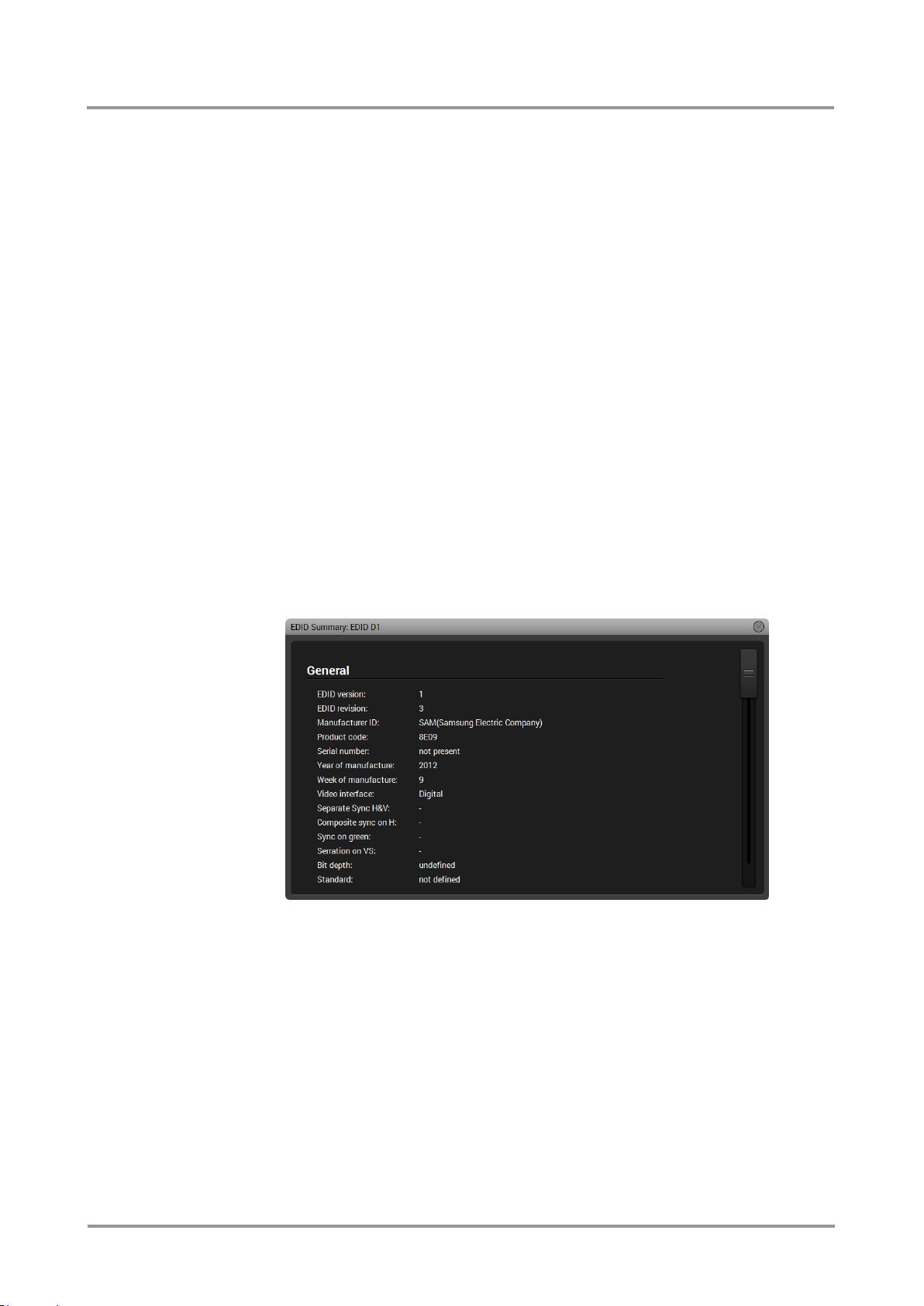
UMX-TPS-TX100 series
User’s Manual
6.8.2. Learning an EDID
Info: The process is the same like changing emulated EDID; the only difference is the
Destination panel: press User button. Thus, one or more EDIDs can be copied into user
memory either from factory memory or from a connected sink (Dynamic).
6.8.3. Exporting an EDID
Source EDID can be downloaded as a file (*.bin, *.dat or *.edid) to the computer.
Step 1. Select desired EDID from the Source panel (highlight with yellow cursor).
Step 2. Press Save button to open Save as dialog and download the file to the computer.
6.8.4. Importing an EDID
Previously saved EDID (*.bin, *.dat or *.edid file) can be uploaded to the user memory:
Step 1. Press User button above Source panel.
Step 2. Select a memory slot from the Source panel.
Step 3. Press the Upload button below Source panel.
Step 4. Browse the file in the opening window then press Open button. Browsed EDID is
imported into the selected User memory.
Info: The imported EDID overwrites the selected memory place even if it is not empty.
6.8.5. EDID Summary window
Select an EDID from Source panel and press Info button to display EDID summary.
Figure 6-5. EDID Summary
6.8.6. Editing an EDID
Select an EDID from Source panel and press Edit button to display Advanced EDID Editor
window. The editor can read and write all descriptors, which are defined in the standards,
including the additional CEA extensions. Any EDID from the device’s memory or a saved
EDID file can be loaded in the editor. The software resolves the raw EDID, and displays it
as readable information to the user. All descriptors can be edited, and saved in an EDID
file, or uploaded to the User memory.
Section 6. Software control – using Lightware Device Controller (LDC) Page 47 / 92
Page 48
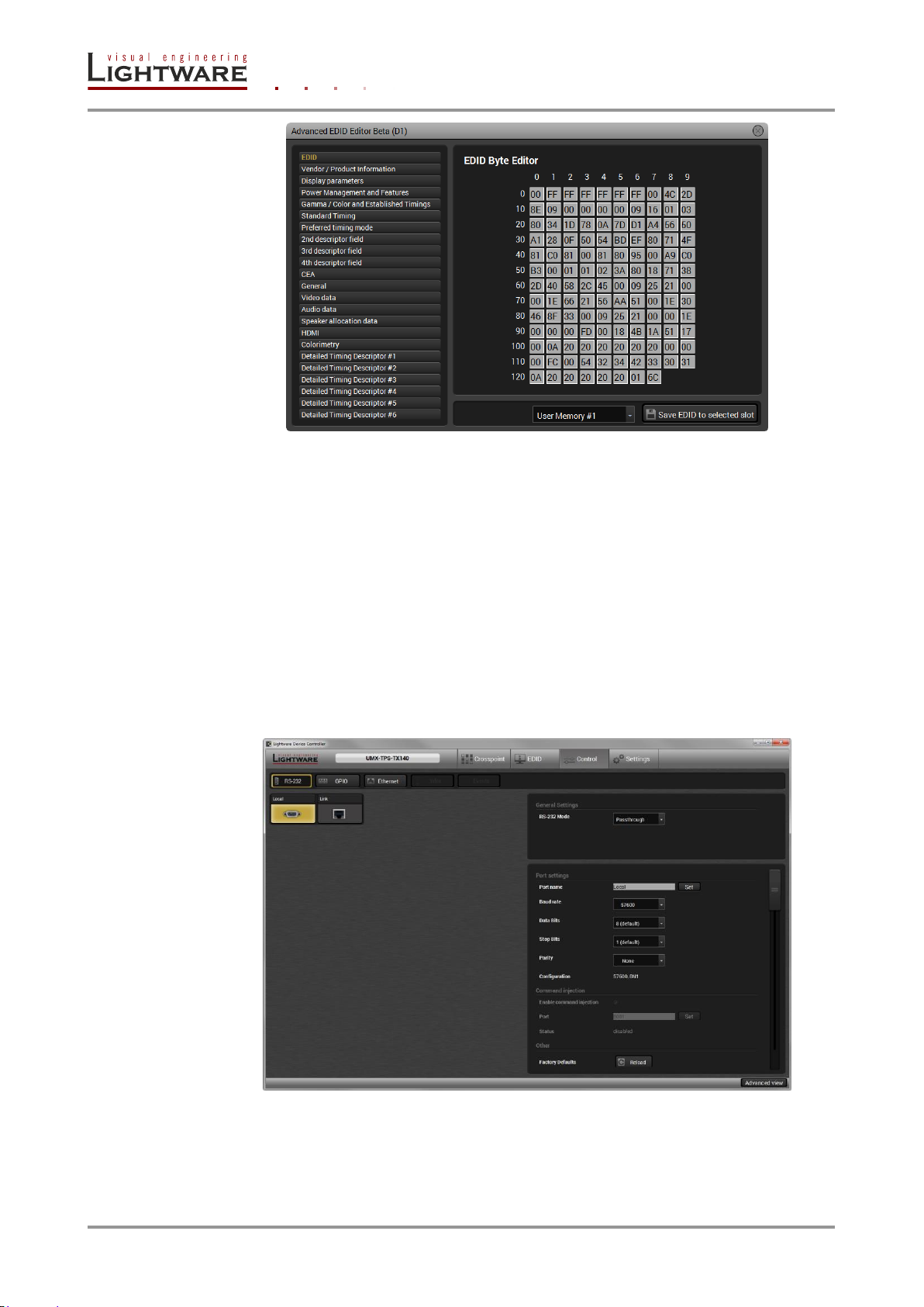
6.8.7. Deleting EDID(s)
The EDID(s) from User memory can be deleted as follows:
Figure 6-6. Advanced EDID Editor
Step 1. Press User button above Destination panel.
Step 2. Select desired memory slot(s); more ports can be selected. Use Select All and
Step 3. Press Clear selected button to delete the EDID(s).
6.9. Control menu
The menu gives the opportunity to setup those channels which can be used to connect or
control third party devices.
Deselect All buttons according to the needs. The EDID(s) will be highlighted with
yellow cursor.
Figure 6-7. Control menu (RS-232 tab)
Page 48 / 92 Section 6. Software control – using Lightware Device Controller (LDC)
Page 49
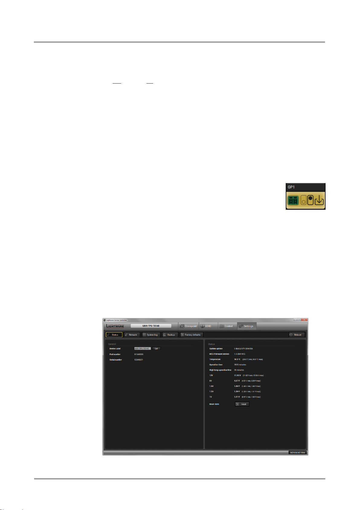
UMX-TPS-TX100 series
User’s Manual
6.9.1. RS-232 settings
General Settings
There are two RS-232 working modes: Pass-through and Control mode. See more details
in section 5.4 on page 32.
Port settings
There are two ports available:
Local: RS-232 connection between the CPU and the 3-pole Phoenix connector
Link: RS-232 connection between the CPU and the receiver unit (via TPS line)
The available settings are the same but different parameters can be set for Local and Link
ports.
Command injection
Under construction.
6.9.2. GPIO settings (only on UMX-TPS-TX140)
The device has 7 GPIO pins, which operates at TTL digital signal levels
and can be controlled with both LDC and protocol commands.
Select a GPIO port and under Port settings section the direction and input
level of each port can be set. The settings are displayed on the port tiles
as well.
6.9.3. Ethernet settings
No special settings are available, just basic information is shown about the communication.
6.10. Settings menu
Device status information and network settings are available in this menu, nevertheless
function buttons help to do operations in connection with logs and device settings.
6.10.1. Status tab
General information is shown on this tab, such as device label, part number, serial number
and hardware health, voltage and temperature values.
Figure 6-8. Status tab
Section 6. Software control – using Lightware Device Controller (LDC) Page 49 / 92
Page 50

6.10.2. Network tab
Network-related settings are available on the tab. If the device has fix IP address, the first
three lines have to be filled with the necessary addresses. If dynamic IP address is used,
the DHCP setting shall be set to be enabled and the addresses are listed below the dropdown menu.
Since the device is able to communicate with LW2 and LW3 protocols, the ports can also
be set here.
Always press the Apply changes button after modification to store the settings; you will be
prompted to reboot the device to apply changes in practice.
6.10.3. Function buttons
System log button
Logged events can be collected and saved into a file which is useful when troubleshooting
or in other special case for analyzing.
Info: Please note that the data collecting may take some minutes. You will be prompted about
log generating before starting.
When the collecting is done, the Save as window appears; select the desired location and
press the Save button.
Backup button
The transmitter’s settings can be saved and loaded. The internal memory is able to store a
pack of settings but you can also save them into a file and load it later.
The buttons have the following functions:
Backup settings: Save the settings into the device’s internal memory
Restore settings: Load and apply the settings from the device’s internal
memory
Load backup from file
Save backup from file
When the settings are restored, you will be asked to reboot (recommended); the connection
will be terminated.
Factory defaults button
Factory default values can be restored by pressing the button; you will be asked to confirm.
The connection will be terminated and the device is rebooted. Factory default values are
listed in section 9.3 on page 87.
Info: Please note that the restoring affects the IP settings as well.
Reboot button
The device can be restarted; the connection will be terminated.
Page 50 / 92 Section 6. Software control – using Lightware Device Controller (LDC)
Page 51
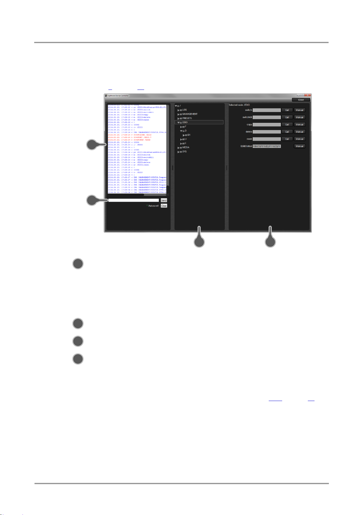
2
1
3 4
1
2
3
4
6.11. Advanced view
Advanced view is the surface for LW3 protocol settings with terminal window. Commands
and specific parameters (which are not available on the user interface) can be run and set.
Detailed information about the protocol, nodes, methods and parameters can be found in
chapter 8 on page 65. Click on Close button to hide Advanced view.
UMX-TPS-TX100 series
User’s Manual
Terminal window Commands and responses are listed in this window. The
timecode in every row shows the exact time when the
command was sent or the response received. Sent command
is displayed in red and starts with ‘>’ character, received
response is displayed in blue and starts with ‘<’ character. The
content of the window can be emptied by the Clear button. If
the Autoscroll option is ticked, the list is scrolled automatically
when a new line is added.
Command line Command text can be typed directly by this field and executed
by the Send button.
Video input ports The protocol tree is available via this panel. Select an item to
see its content.
Node list Correspondent parameters and nodes are shown which are
connected to the selected item in the protocol tree.
Manual button: Manual (short description) of the node can
be called and displayed in the terminal
window. See more information about
manuals in section 8.3.4 on page 72.
Set button: Saves the value/parameter typed in the
textbox.
Call button: Calls the method, e.g. reloads factory
default settings.
Section 6. Software control – using Lightware Device Controller (LDC) Page 51 / 92
Page 52

Format
Example
Command
{i} → {i}
Response
(I:<PRODUCT_TYPE>)CrLf
←
(I:UMX-TPS-TX140)CrLf
Format
Example
Command
{P_?}
→
{P_?}
Response
(CURRENT●PROTOCOL●=
●#<protocol>)CrLf
←
(CURRENT PROTOCOL = #1)CrLf
7. LW2 Programmer’s reference
The device can be monitored through a reduced command set of LW2 protocol commands
to ensure the compatibility with other Lightware products. The supported LW2 commands
are described in this chapter.
7.1. LW2 protocol description
The device accept commands surrounded by curly brackets - { } - and responds data
surrounded by round brackets - ( ) - only if a command was successfully executed.
Legend for control commands:
<in> = input number in 1 or 2 digit ASCII format (01,5,07,16 etc.)
<out> = output number in 1 or 2 digit ASCII format
<in²> = input number in 2 digit ASCII format (01, 02, 10, 12 etc.)
<out²> = output number in 2 digit ASCII format (01, 02, 10, 12 etc.)
<loc> = location number in 1, 2 or 3 digit ASCII format
<id> = id number in 1 or 2 digit ASCII format
<id²> = id number in 2 digit ASCII format
CrLf = Carriage return, Line feed (0x0D, 0x0A)
● = space character (0x20)
→ = each command issued by the controller
← = each response received from the router
7.2. General LW2 commands
7.2.1. View product type
Description: The transmitter responds its name.
Explanation: The connected device is a UMX-TPS-TX140.
Legend: <PRODUCT_TYPE> shows type.
7.2.2. Query control protocol
Description: The transmitter can be controlled with different control protocols. This
command queries the active protocol for the used control interface.
Explanation: The device communicates with LW2 protocol.
Page 52 / 92 Section 7. LW2 Programmer’s reference
Page 53

UMX-TPS-TX100 series
Format
Example
Command
{f} → {f}
Response
(FW:<FW_VER><s>)CrLf
←
(FW:1.0.0b4 r972)CrLf
Format
Example
Command
{PING}
→
{ping}
Response
(PONG!)CrLf
←
(PONG!)CrLf
Format
Example
Command
{s} → {s}
Response
(SN:<SERIAL_N>)CrLf
←
(SN:12345671)CrLf
Format
Example
Command
{CT}
→
{ct}
Response
(Complied: <DATE&TIME>)
CrLf
←
(Compiled: Sep 11 2014 18:05:41)
CrLf
Format
Example
Command
{is} → {is}
Response
(SL#●0●<MB_DESC>)CrLf
(SL●END)CrLf
←
←
(SL# 0 UMX-TPS-TX140 V10_2a)
CrLf
(SL END)CrLf
Format
Example (MX-FR17)
Command
{FC}
→
{fc}
Response
(CF●<DESC>)CrLf
(CF●<DESC>)CrLf
…
(CF END)CrLf
←
←
(CF UMX-TPS-TX140 1.0.0b4
r972)CrLf
(CF END) CrLf
User’s Manual
7.2.3. View firmware version of the CPU
Description: View the CPU firmware revision.
Legend: <FW_VER> is the firmware version. It is followed by <s> string which may indicate
special versions. <s>=r indicates standard version.
7.2.4. Connection test
Description: Simple test to see if the connection is established successfully.
7.2.5. View serial number
Description: The transmitter responds its 8-digit serial number.
7.2.6. Compile time
Description: Returns the date, when the microcontroller firmware was compiled.
7.2.7. View installed board(s)
Description: Shows the hardware name and revision of the installed cards. The number
of responses (number of slots e.g. in matrices) depend on the connected device.
Explanation: The device reports its motherboard (slot 0).
7.2.8. View firmware for all controllers’
Description: Shows the firmware versions of all installed controllers. The number of
responses depends on the router configuration.
Explanation: The device has one control panel.
Section 7. LW2 Programmer’s reference Page 53 / 92
Page 54
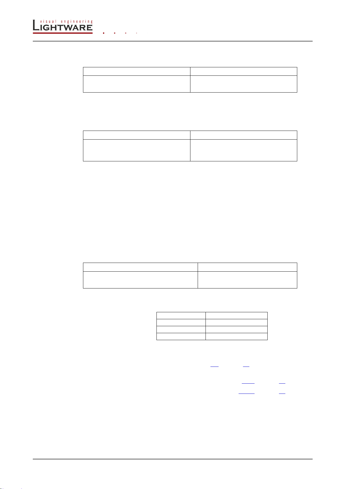
Format
Example
Command
{RST}
→
{RST}
Response
Format
Example
Command
{ST}
→
{st}
Response
(ST●<DESC>)CrLf
←
(ST CPU 11.96V 5.15V 1.86V 1.31V
1.01V 51.84C)CrLf
Format
Example
Command
{<in>@<out>●<layer>}
→
{2@1 av}
Response
(O<out²>●I<in²>●<layer>)CrLf
←
(O01 I02 AV)CrLf
<layer>
Layer
A
Audio layer
V
Video layer
AV (or nothing)
Audio & Video layer
7.2.9. Restart matrix router
Description: The device can be restarted without unplugging power.
Explanation: The device reboots; no response is sent in this case.
7.2.10. Query state
Description: Queries health status. Response depends on the connected device.
Explanation: Internal voltages and measured temperature values are shown.
7.3. Crosspoint switching LW2 commands
7.3.1. Switch one input to one output
Following commands with <A/V/AV> option can take effect in multiple layers, according to
their parameters. Depending on ‘A’ or ‘V’ it can change only the Audio, or only the Video
layer; or ‘AV’ changes both.
Info: <A/V/AV> option usually can be skipped for legacy purposes. In this case the devices
changes all (Video & Audio) layers, but using status commands it displays information
about only the Video layer. Please use AV option, when available.
Description: Switch input <in> to output <out>.
Explanation: Audio and video input 2 are switched to the output.
Legend: <layer>:
<out>: TPS output, type “O1” always.
<in> can be: Input port. The port numbering is different in the devices. See
the details in section 9.5 on page 90.
Info: The response of this command does not show if the output is muted. To check the mute
status a separate query has to be used like {VC}. See section 7.3.6 on page 56.
Info: To achieve multiple switches executed together, see section 7.3.16 on page 59.
Page 54 / 92 Section 7. LW2 Programmer’s reference
Page 55
UMX-TPS-TX100 series
Format
Example
Command
{#<out>●<layer>}
→
{#01 A}
Response
(1MT<out²>●<layer>)CrLf
←
(1MT01 A)CrLf
Format
Example
Command
{+<out>●<layer>}
→
{+01 A}
Response
(0MT<out²>●<layer>)CrLf
←
(0MT01 A)CrLf
Format
Example
Command
{#><out>●<layer>}
→
{#>01 A}
Response
(1LO<out²>●<layer>)CrLf
←
(1LO01 A)CrLf
Format
Example
Command
{+<<out>●<layer>}
→
{+<01 A}
Response
(0LO<out²>●<layer>)CrLf
←
(0LO01 A)CrLf
User’s Manual
7.3.2. Mute specified output
Description: Mute output <out>. The output signal is turned off.
Explanation: The audio channel of the TPS output is muted.
Legend: See section 7.3.1 on page 54.
Info: Muting does not change the crosspoint’s state, but disables the output itself. This way the
last connection can be easily restored with an unmute command.
Info: Switching a muted output does not unmute the output.
7.3.3. Unmute specified output
Description: Unmute output <out>.
Explanation: The audio channel of the TPS output is muted.
Legend: See section 7.3.1 on page 54.
Info: Unmuting an output makes the previous connection active as the crosspoint’s state has not
been changed with the muting command, only the output was disabled.
7.3.4. Lock the output
Description: Lock output <out>. Output’s state cannot be changed until unlocking.
Explanation: Audio channel of the TPS output is locked.
Legend: See section 7.3.1 on page 54.
7.3.5. Unlock the output
Description: Unlock output <out>. The connection on output can be changed.
Explanation: Audio channel of the TPS output is unlocked.
Section 7. LW2 Programmer’s reference Page 55 / 92
Legend: See section 7.3.1 on page 54.
Info: The device issues the above response regardless of the previous state of the output (either
it was locked or unlocked).
Page 56
Format
Example
Command
{VC●<layer>}
→
{vc av}
Response
(ALL<layer>●<in2>)CrLf
← ← (ALLV 02)CrLf
(ALLA 01)CrLf
<layer>
Layer
A
Audio layer
V
Video layer
AV*
Audio & Video layer
Format
Example
Command
{getsize●<layer>}
→
{getsize av}
Response
(SIZE=<size>●<layer>)CrLf
← ← (SIZE=6x1 V)CrLf
(SIZE=5x1 A)CrLf
Format
Example
Command
{AS_V<out>=?}
→
{as_v1=?}
Response
(AS_V<out>=<state>;
<mode>;<no_signal>)CrLf
←
(AS_V1=E;K;B)CrLf
7.3.6. View connection state on the output
Description: Viewing the output’s connection results in different response length, because
it depends on the device. The response below refers to an UMX-TPS-TX140.
Legend: <layer>:
* AV is not used in response. When AV is typed in the commands, the response will result
two lines, one for Audio and one for the Video state.
Explanation: Video input port 2 and audio input port 1 are switched to the TPS output.
Info: If an output is locked, muted, or both locked and muted, the response format changes. If
outputs are muted you get a letter 'M', if locked a letter 'L' and if muted and locked at the
same time 'U' before the 2 digit numbers.
7.3.7. View crosspoint size
Description: Shows the physical crosspoint size.
Legend: <size>: <number of inputs>x<number of outputs>
<layer>: See section 7.3.6 on page 56.
Explanation: The device reports that it has a video crosspoint with 6 inputs and 1 output,
and an audio crosspoint with 5 inputs and 1 output.
7.3.8. Query video Autoselect mode
Description: The autoselect mode of video output can be queried.
Legend: <out>: The output port number (1). See more details about port
numbering in section 9.5 on page 90.
<state>: E = Autoselect is enabled; D = Autoselect is disabled
Page 56 / 92 Section 7. LW2 Programmer’s reference
<mode>: P = Priority detect; K = First detect (keep first)
<no_signal>: B = Blank screen; M = Mute output
Explanation: The device reports that the Autoselect mode is enabled in first detect mode,
and if there is no incoming signal at all, the crosspoint is not changed (blank screen).
Page 57

UMX-TPS-TX100 series
Format
Example
Command
{AS_V<out>=<state>;
<mode>;<no_signal>}
→
{as_v1=E;K;B}
Response
(AS_V<out>=<state>;
<mode>;<no_signal>)CrLf
←
(AS_V1=E;K;B)CrLf
Format
Example
Command
{AS_A<out>=?}
→
{as_a1=?}
Response
(AS_A<out>=<state>;
<mode>;<no_signal>)CrLf
←
(AS_A1=E;K;B)CrLf
Format
Example
Command
{AS_A<out>=<state>;
<mode>;<no_signal>}
→
{as_a1=E;K;B}
Response
(AS_A<out>=<state>;
<mode>;<no_signal>)CrLf
←
(AS_A1=E;K;B)CrLf
Format
Example
Command
{PRIO_V<out>=?
→
{prio_v1=?}
Response
(PRIO_V<out>=<in1_prio>;
<in2_prio>;..;<inn_prio>)CrLf
←
(PRIO_V1=1;0;2;3;4;31)CrLf
User’s Manual
7.3.9. Change video Autoselect mode
Description: The autoselect mode of video output can be changed.
Legend: See section 7.3.8 on page 56.
Explanation: The Autoselect mode is enabled in first detect mode, and if there is no
incoming signal at all, the crosspoint is not changed (blank screen).
7.3.10. Query audio Autoselect mode
Description: The autoselect mode of audio output can be queried.
Legend: <out>: The output port number (1). See more details about port
numbering in section 9.5 on page 90.
<state>: E = Autoselect is enabled; D = Autoselect is disabled
<mode>: P = Priority detect; K = First detect (keep first)
<no_signal>: B = Blank; M = Mute output
Explanation: The device reports that the Autoselect mode is enabled in first detect mode,
and if there is no incoming signal at all, the crosspoint is not changed.
7.3.11. Change audio Autoselect mode
Description: The autoselect mode of video output port can be changed.
Legend: See section 7.3.8 on page 56.
Explanation: The Autoselect mode is enabled in first detect mode, and if there is no
incoming signal at all, the crosspoint is not changed.
7.3.12. Query video input priorities
Section 7. LW2 Programmer’s reference Page 57 / 92
Description: The settings of video input priority can be queried as follows.
Legend: <out>: The output port number (1).
<in1_prio>…<inn_prio>: Input ports’ priority number. See more details
about port numbering in section 9.5 on page 90.
Explanation: P2 has the highest priority (0), P1 has the second highest priority number
(1). P6 has priority 31 which is the lowest possible setting; it means P6 is disabled from the
priority list and cannot be selected.
Page 58

Format
Example1
Command
{PRIO_V<out>=<in1_prio>;
<in2_prio>;…;<inn_prio>)
→
{prio_v1=1;0;2;3;4;5}
Response
(PRIO_V<out>=<in1_prio>;
<in2_prio>;…;<inn_prio>)CrLf
←
(PRIO_V1=1;0;2;3;4;5)CrLf
Format
Example
Command
{PRIO_A<out>=?
→
{prio_a1=?}
Response
(PRIO_A<out>=<in1_prio>;
<in2_prio>;..;<inn_prio>)CrLf
←
(PRIO_A1=1;0;2;3;4;31)CrLf
Format
Example1
Command
{PRIO_A<out>=<in1_prio>;
<in2_prio>;…;<in
n
_prio>)
→
{prio_a1=1;0;2;3;4;5}
Response
(PRIO_A<out>=<in1_prio>;
<in2_prio>;…;<in
n
_prio>)CrLf
←
(PRIO_A1=1;0;2;3;4;5)CrLf
7.3.13. Change video input priorities
Description: The settings of video input priority can be changed as follows.
Legend: <out>: The output port number (1).
<in1_prio>…<inn_prio>: Input ports’ priority number. See more details about
port numbering in section 9.5 on page 90.
Explanation: P2 has the highest priority (1), P1 has the second highest (2). P5 has the
lowest priority (5).
Info: Always set all the ports’ priority when changing, otherwise the change will not be executed
and the response will be the current setting (like querying the priority setting).
7.3.14. Query audio input priorities
Description: The settings of audio input priority can be queried as follows.
Legend: <out>: The output port number (1).
<in1_prio>…<inn_prio>: Input ports’ priority number. See more details
about port numbering in section 9.5 on page 90.
Explanation: P2 has the highest priority (0), P1 has the second highest priority number
(1). P6 has priority 31 which is the lowest possible setting; it means P6 is disabled from the
priority list and cannot be selected.
7.3.15. Change audio input priorities
Description: The settings of audio input priority can be changed as follows.
Legend: <out>: The output port number (1).
<in1_prio>…<inn_prio>: Input ports’ priority number. See more details about
port numbering in section 9.5 on page 90.
Explanation: P2 has the highest priority (1), P1 has the second highest (2). P5 has the
lowest priority (5).
Info: Always set all the ports’ priority when changing, otherwise the change will not be executed
and the response will be the current setting (like querying the priority setting).
Page 58 / 92 Section 7. LW2 Programmer’s reference
Page 59

UMX-TPS-TX100 series
One by one commands
Batch commands
→
{02@01 V}CrLf
→
{02@01 V}{01@01 A}CrLf
←
(O01 I02 V)CrLf
← ← (O01 I02 V)CrLf
(O01 I01 A)CrLf
→
{01@01 A}CrLf
←
(O01 I01 A)CrLf
Format
Example
Command
{RS232=?}
→
{rs232=?}
Response
(RS232=<mode>)CrLf
←
(RS232=CONTROL)CrLf
Format
Example
Command
{RS232=<mode>}
→
{rs232=pass}
Response
(RS232=<mode>)CrLf
←
(RS232=PASS)CrLf
User’s Manual
7.3.16. Batch switch outputs
Description: The device is capable of switching multiple outputs exactly at the same time.
To do this, the normal switch commands have to be used. If the switch commands arrive
to the device with less than 10 milliseconds delay, the commands are collected and
changes the output connections together.
Required circumstances:
Switch commands have this format: {<in>@<out>}{<in>@<out>}
The delay between two ‘}’ characters must be below 10 milliseconds
No other command or junk character is allowed between switch commands
Affected outputs must not be locked
If any of the above circumstances fail, then the commands will be processed separately
and the output connections will change one by one.
Info: The delay timeout applies for the receiving time of characters. Please note that if LAN
connection is used then the network may cause additional delays. This could result that
batch switching does not occur.
The below example shows a command that resulted batch switching:
7.4. RS-232-specific LW2 commands
7.4.1. Query the RS-232 mode
Description: The RS-232 mode can be queried as follows:
Legend: <mode>: CONTROL = Control mode is enabled
PASS = Pass mode is enabled
Explanation: Current RS-232 mode is Control mode.
7.4.2. Change RS-232 mode
Description: The RS-232 mode can be changed as follows:
Legend: See section 7.4.1 on page 59.
Explanation: The RS-232 mode is set to Pass mode.
Section 7. LW2 Programmer’s reference Page 59 / 92
Page 60

Format
Example1
Command
{RS232_LOCAL_FORMAT=?}
→
{rs232_local_format=?}
Response
(RS232_LOCAL_FORMAT=
<baud>;<data bits>; <parity>;
<stop bits>)CrLf
←
(RS232_LOCAL_FORMAT=57600;
8;N;1)CrLf
Format
Example2
Command
{RS232_LINK_FORMAT=?}
→
{rs232_link_format=?}
Response
(RS232_LINK_FORMAT=
<baud>;<data bits>;
<parity>; <stop bits>)CrLf
←
(RS232_LINK_FORMAT=9600;
8;N;1)CrLf
Format
Example1
Command
{RS232_LOCAL_FORMAT=
<baud>;<data bits>;
<parity>; <stop bits>}
→
{rs232_local_format=57600;9;N;1}
Response
(RS232_LOCAL_FORMAT=
<baud>;<data bits>;
<parity>; <stop bits>)CrLf
←
(RS232_LOCAL_FORMAT=57600;
9;N;1)CrLf
Format
Example2
Command
{RS232_LINK_FORMAT=
<baud>;<data bits>;
<parity>; <stop bits>}
→
{rs232_link_format=9600;9;N;1}
Response
(RS232_LINK_FORMAT=
<baud>;<data bits>;
<parity>; <stop bits>)CrLf
←
(RS232_LINK_FORMAT=9600;
9;N;1)CrLf
7.4.3. Query the RS-232 port settings (local or link port)
Description: The RS-232 port settings can be queried as follows:
Legend: <baud>: Baud rate which can be 4800, 7200, 9600, 14400, 19200,
38400, 57600, 115200
<data bits>: 8 or 9
<parity>: N (none), O (odd), E (even)
<stop bits>: 1, 1.5, 2
Explanation1: Current RS-232 settings on local port: Baud rate is 57600, 8 data bits, no
parity, 1 stop bit.
Legend: Same as above.
Explanation2: Current RS-232 settings on link port: Baud rate is 9600, 8 data bits, no
parity, 1 stop bit.
7.4.4. Change RS-232 port settings (local or link port)
Description: The RS-232 port settings can be set as follows:
Legend: See section 7.4.3 on page 60.
Explanation1: RS-232 settings on local port have been set as follows: Baud rate is 57600,
9 data bits, no parity, 1 stop bit.
Legend: See section 7.4.3 on page 60.
Explanation2: RS-232 settings on local port have been set as follows: Baud rate is 9600,
9 data bits, no parity, 1 stop bit.
Page 60 / 92 Section 7. LW2 Programmer’s reference
Page 61

UMX-TPS-TX100 series
Format
Example1
Command
{RS232_LOCAL_PROT=?}
→
{rs232_local_prot=?}
Response
(RS232_LOCAL_PROT=
<protocol>)CrLf
←
(RS232_LOCAL_PROT=
LW2)CrLf
Format
Example2
Command
{RS232_LINK_PROT=?}
→
{rs232_link_prot=?}
Response
(RS232_LINK_PROT=
<protocol>)CrLf
←
(RS232_LINK_PROT=
LW2)CrLf
Format
Example1
Command
{RS232_LOCAL_PROT=
<protocol>}
→
{rs232_local_prot=LW3}
Response
(RS232_LOCAL_PROT=
<protocol>)CrLf
←
(RS232_LOCAL_PROT=LW3)CrLf
Format
Example2
Command
{RS232_LINK_PROT=
<protocol>}
→
{rs232_link_prot=LW3}
Response
(RS232_LINK_PROT=
<protocol>)CrLf
←
(RS232_LINK_PROT=LW3)CrLf
Format
Example
Command
{IP_STAT=?
→
{ip_stat=?}
Response
(IP_STAT=<type>;<ip_
address>;<subnet_mask>;
<gateway_addr>)CrLf
←
(IP_STAT=1;192.168.0.102;
255.255.255.0;192.168.0.1)CrLf
User’s Manual
7.4.5. Query the RS-232 protocol (local or link port)
Description: The RS-232 protocol can be queried as follows:
Legend: <protocol>: LW2 or LW3
Explanation1: Current protocol on local RS-232 port is LW2.
Legend: <protocol>: LW2 or LW3
Explanation2: Current protocol on link RS-232 port is LW2.
7.4.6. Change RS-232 protocol (local or link port)
Description: The RS-232 protocol can be set as follows:
Legend: <protocol>: LW2 or LW3
Explanation1: Current protocol on local RS-232 port is set to LW3.
Legend: <protocol>: LW2 or LW3
Explanation2: Current protocol on link RS-232 port is set to LW3.
7.5. Further LW2 commands
7.5.1. Query the IP status
Description: IP address settings can be queried as follows.
Legend: <type>: 0 = fix IP; 1 = DHCP.
<ip_addr>: IP address (four decimal octets separated by dots)
<subnet_mask>: Subnet mask (four decimal octets separated by dots)
<gateway_addr>: Gateway address (four decimal octets separated by dots)
Explanation: The device has a dynamic IP address: 192.168.0.102; subnet mask is
255.255.255.0, gateway address is 192.168.0.1.
Section 7. LW2 Programmer’s reference Page 61 / 92
Page 62

7.5.2. Query the IP address
Format
Example
Command
{IP_ADDRESS=?}
→
{ip_address=?}
Response
(IP_ADDRESS=<type>;
<ip_address>)CrLf
←
(IP_ADDRESS=0;192.168.0.100)
CrLf
Format
Example
Command
{IP_ADDRESS=<type>;
<ip_address>}
→
{ip_address=0;192.168.0.100}
Response
(IP_ADDRESS=<type>;
<ip_address>)CrLf
←
(IP_ADDRESS=0;192.168.0.100)
CrLf
Format
Example
Command
{IP_NETMASK=?
→
{ip_netmask=?}
Response
(IP_NETMASK=<subnet_
mask>)CrLf
←
(IP_NETMASK=255.255.255.0)CrLf
Format
Example
Command
{IP_NETMASK=<subnet_
mask>
→
{ip_netmask=255.255.255.0}
Response
(IP_NETMASK=<subnet_
mask>)CrLf
←
(IP_NETMASK=255.255.255.0)CrLf
Format
Example
Command
{IP_GATEWAY=?
→
{ip_gateway=?}
Response
(IP_GATEWAY=<gateway_
addr>)CrLf
←
(IP_GATEWAY=192.168.0.1)CrLf
Description: IP address can be queried from the device with this command.
Legend: <type>: 0 = fix IP; 1 = DHCP
Explanation: The device has a fix IP address: 192.168.0.100.
7.5.3. Set the IP address
Description: IP address can be set as follows.
Legend: <type>: 0 = fix IP; 1 = DHCP
Explanation: The device has a fix IP address 192.168.0.100.
Info: Restarting the transmitter is necessary to apply the changes after modification.
7.5.4. Query the subnet mask
Description: Subnet mask can be queried as follows.
Legend: <subnet_mask>: Four decimal octets separated by dots.
7.5.5. Set the subnet mask
Description: Subnet mask can be set as follows.
Legend: <subnet_mask>: Four decimal octets separated by dots.
Explanation: The subnet mask is set to 255.255.255.0.
7.5.6. Query the gateway address
Description: Gateway address can be queried as follows.
Legend: <gateway_addr>: Four decimal octets separated by dots.
Page 62 / 92 Section 7. LW2 Programmer’s reference
Page 63

UMX-TPS-TX100 series
Format
Example
Command
{IP_GATEWAY=<gateway_
addr>
→
{ip_gateway=192.168.0.50}
Response
(IP_GATEWAY=<gateway_
addr>)CrLf
←
(IP_GATEWAY=192.168.0.50)CrLf
Format
Example1
Command
{LW2_PORT=?
→
{lw2_port=?}
Response
(LW2_PORT=<port_nr>)CrLf
←
(LW2_PORT=10001)CrLf
Format
Example2
Command
{LW3_PORT=?
→
{lw3_port=?}
Response
(LW3_PORT=<port_nr>)CrLf
←
(LW3_PORT=6107)CrLf
Format
Example1
Command
{LW2_PORT=<port_nr>
→
{lw2_port=10001}
Response
(LW2_PORT=<port_nr>)CrLf
←
(LW2_PORT=10001)CrLf
Format
Example2
Command
{LW3_PORT=<port_nr>
→
{lw3_port=6107}
Response
(LW3_PORT=<port_nr>)CrLf
←
(LW3_PORT=6107)CrLf
Format
Example
Command
{GPIO<pin_nr>=?
→
{gpio1=?}
Response
(GPIO<pin_nr>=<direction>;
<level>)CrLf
←
(GPIO1=I;H)CrLf
User’s Manual
7.5.7. Set the gateway address
Description: Gateway address can be set as follows.
Legend: <gateway_addr>: Four decimal octets separated by dots.
Explanation: The gateway address is set to 192.168.0.50.
7.5.8. Query the TCP/IP port
Description: TCP/IP port setting can be queried as follows.
Explanation1: The port number for LW2 protocol is 10001 (default value).
Explanation2: The port number for LW3 protocol is 6107 (default value).
7.5.9. Set the TCP/IP port
Description: TCP/IP port setting can be set as follows.
Explanation1: The port number for LW2 protocol is set to 10001 (default value).
Explanation2: The port number for LW3 protocol is set to 6107 (default value).
7.5.10. Query the state of a GPIO pin
Description: The state of a GPIO pin can be queried as follows.
Legend: <pin_nr>: GPIO pin number (1-7).
<direction>: Direction of the pin: I = input, O = output
<level>: H = high level, L = low level.
Explanation: GPIO pin #1 is input, input level is high.
Section 7. LW2 Programmer’s reference Page 63 / 92
Page 64

7.5.11. Set the state of a GPIO pin
Format
Example
Command
{GPIO<pin_nr>=<direction>;
<level>
→
{gpio1=i;l}
Response
(GPIO<pin_nr>=<direction>;
<level>)CrLf
←
(GPIO1=I;L)CrLf
Description: The state of a GPIO pin can be set as follows.
Legend: See section 7.5.10 on page 63.
Explanation: GPIO pin #1 is set as input, input level is low.
Page 64 / 92 Section 7. LW2 Programmer’s reference
Page 65

UMX-TPS-TX100 series
User’s Manual
8. LW3 Programmers’ reference
8.1. Overview
Lightware 3 (LW3) protocol is currently used by UMX-TPS-TX100 series, MODEX family,
25G product line and will be the preferred protocol in new developments.
The protocol (LW3) is ASCII-based and all commands are terminated with a carriage return
(Cr, ‘\r’) and line feed (Lf, ‘\n’) pair. It is organized as a tree structure that provides
outstanding flexibility for implementing a human readable, but still easy to programmatically
parse protocol, which is suitable for different products with different feature list.
In order to implement a flexible, easy-to-use protocol that is straightforward to adapt to new
devices and provides outstanding scalability and sustainability, we decided to organize all
settings, parameters and properties of the device to a tree structure with ‘nodes’,
‘properties’ and ‘methods’.
8.1.1. Elements of the tree structure
Important! All names and values are case sensitive. The space character is replaced by ‘●’ character
in the elements and commands descriptions.
Node
The basic building block of the tree structure is the ‘node’.
A node can have multiple child nodes, but only one parent.
The tree has only one root the ‘root node’.
The leaves of the tree are also nodes, which do not have child nodes.
The nodes are separated by a slash (‘/’) character.
All the slashes are ‘right slashes’, no backslash is used.
The identifier of the root node it a slash (‘/’)
Nodes’ name can contain the elements of the English alphabet and numbers.
Recommended convention for case sensitivity:
- Fix nodes (that cannot be altered) are capitalized.
- User created nodes can contain both lowercase and capital letters, no
restrictions.
The path of a node has to contain all parent nodes from the root node.
Format (the root node): nX●/
Path: nX●/[nodeName]/[nodeName]/[nodeName]
Legend: ‘n’: node
‘X’ can be:
‘-’: default for a node,
‘m’: this is a manual for the node,
‘E’: this is an error message for the node.
Info: All parent nodes must be listed in the path of a node.
Following example presents the structure of the tree traversal:
Section 8. LW3 Programmers’ reference Page 65 / 92
Page 66
Path of the nodes:
n-/node3
n-/
node11
node1
node12
node2
node21
node211
node3
n-/node1
n-/node1/node11
n-/node1/node12
n-/node2
n-/node2/node21
n-/node2/node21/node211
Figure 8-1. Tree structure of nodes
Property
The ‘property’ in the LW3 protocol is basically a leaf, which has a well-defined value.
A property has a value.
A property cannot have child nodes or child properties. It is always a leaf.
A node can have any number of properties (may not have any).
A property is referenced with a dot (‘.’) after the node name.
The properties’ name can contain the elements of the English alphabet, numbers
and underscore (‘_’) character.
By convention, properties are beginning with capital letter, all other characters are
lowercase ones. In case of compound words, all words are beginning with a capital
letter (CamelCase).
The value of the property can contain any readable ASCII character.
A property can be read-only or read/write.
Format: pX●/[nodeName].[propertyName]=[propertyValue]
Legend: p: property
X can be:
‘r’: if the property is read-only.
‘w’: if the property is readable, writable.
‘m’: manual for the property.
‘E’: error message for the property.
Example:
Page 66 / 92 Section 8. LW3 Programmers’ reference
The following two ones are read-only properties:
pr●/node1/node12.ReadOnlyProperty=value1
pr●/.DeviceName=25G Hybrid Device
The following two ones are read-write properties:
pw●/node1/node12.ReadWriteProperty=value2
pw●/.DeviceNickName=John
Page 67

UMX-TPS-TX100 series
User’s Manual
Method
The ‘method’ in the LW3 protocol is also a leaf. It cannot have a value, such as the
properties, but it can be invoked with a parameter with the help of a special ‘CALL’
command.
A method cannot have child nodes or child methods. It is always a leaf.
A node can have any number of methods (may not have any).
A method is referenced with a colon (‘:’) after the node.
The methods’ name can contain the elements of the English alphabet, numbers
and underscore (‘_’) character.
By convention, methods are beginning with lowercase letter. In case of compound
words, the very first letter is lowercase, and the first letter of each other words are
capitalized (lowerCamelCase).
The parameter of the method can contain any readable ASCII character.
The method always has a return ‘state’ if the method could be executed. The state
could be either ‘OK’ or ‘FAILED’.
The method not necessarily has a return ‘value’. If it does, it can contain additional
information, which is always specific for the current case (the return value can
specify why the execution failed).
When the method cannot be executed (e.g. the parameter list is illegal), there is an
error message.
Format: mX●/[nodeName]:[methodName]=[returnValue]
Legend: m: method
X can be:
‘O’: when the execution of the method was successful (OK),
‘F’: when the execution of the method failed,
‘m’: manual for the method,
‘E’: error message for the method.
Example:
mO●/node1/node12:method1
mO●/MEDIA/VIDEO/XP1:switch
mE●%E001:Syntax error
mm●/MEDIA/VIDEO/XP1:lockSource:Lock one or more source ports
8.1.2. Escaping
Property values and method parameters can contain characters that are used as control
characters in the protocol. They must be escaped. The escape character is the backslash
(‘\’) and escaping means injecting a backslash before the character that should be escaped
(like in C language).
Control characters are the followings: \ { } # % ( ) \r \n \t
Example:
The original text: John●(Doe).●#3:●5%2=1●node1\node11
The escaped text: John●\(Doe\).●\#3:●5\%2=1●node1\\node11
Section 8. LW3 Programmers’ reference Page 67 / 92
Page 68

8.1.3. Error messages
There are several error messages defined in the LW3 protocol. All of them have a unique
error number which can be used programmatically, and an informative error message.
Format: XE●[primitive]●%EYYY:●[Error message]
Legend: X can be:
‘-’: syntax error. Cannot parse the command at all.
‘n’: node error.
‘p’: property error.
‘m’: method error.
YYY: error code, which can be one of the followings:
E001 Syntax error E010 Illegal parameter count
E002 Node not found E011 Item already exist
E003 EOL expected E012 Item does not exist
E004 Writing read-only property E013 Illegal operation
E005 Invalid value E014 Internal error
E006 Property does not exist E015 Access denied
E007 Syntax error E016 Write access denied
E008 Illegal method E017 Reserved
E009 Method does not exist E018 Waiting timeout
8.1.4. Prefix summary
The following prefixes are defined in the LW3 protocol:
‘n-’: a node,
‘nE’: an error for a node,
‘nm’: a manual for a node,
‘pr’: a read-only property,
‘pw’: read-write property,
‘pE’: an error for the property,
‘pm’: a manual for the property,
‘m-’: a method,
‘mO’: a response after a success method execution,
‘mF’: a response after a failed method execution,
‘mE’: an error for a method,
‘mm’: a manual for a method.
Page 68 / 92 Section 8. LW3 Programmers’ reference
Page 69
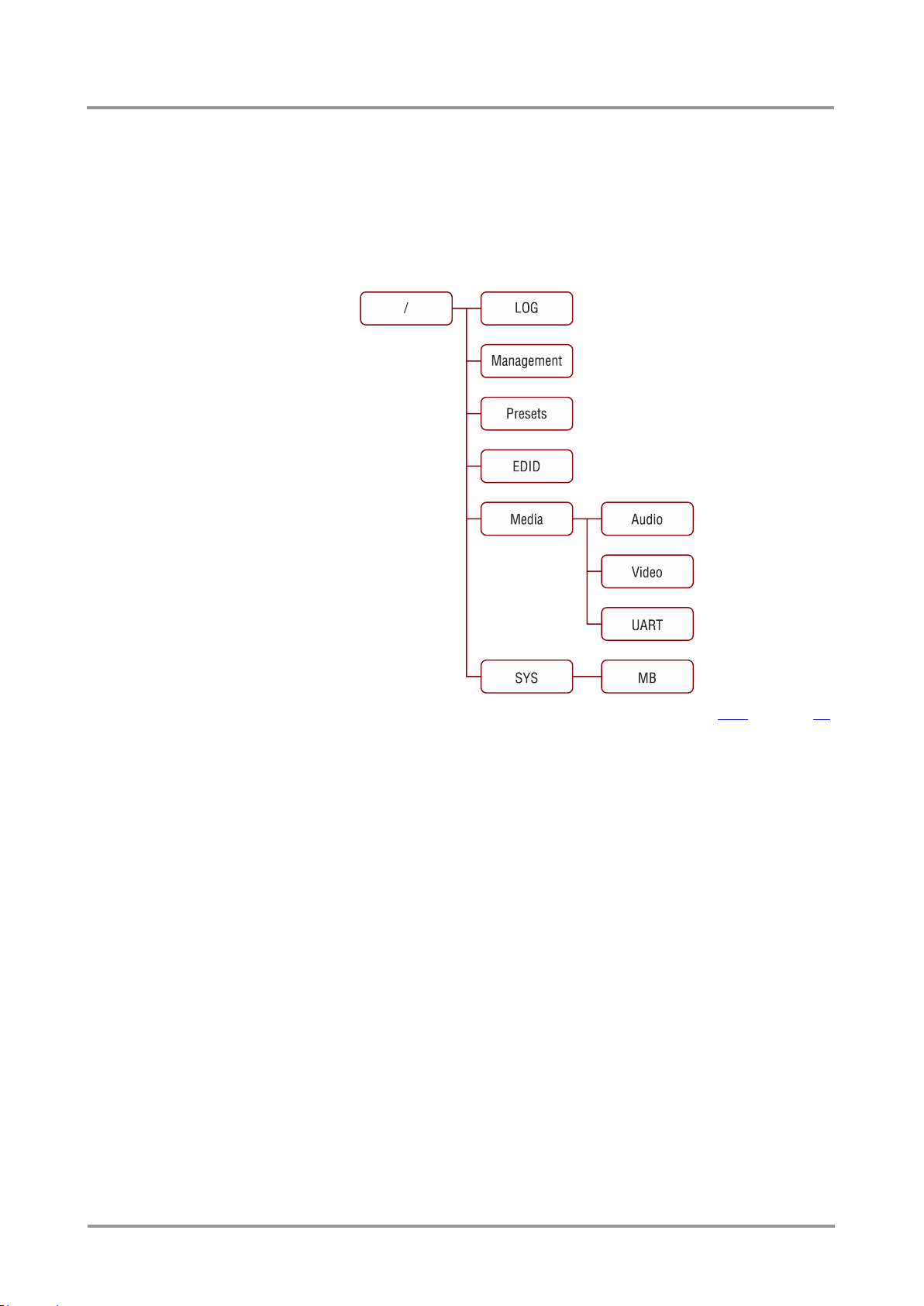
8.2. The tree structure of UMX-TPS devices
The Control Software uses the /MEDIA node to connect input ports to output ports on
different layers. Each subnode of /MEDIA is representing a layer, for example video
(/MEDIA/VIDEO), audio (/MEDIA/AUDIO) or RS-232 (/MEDIA/UART). Each layer has a
crosspoint to define connections between the ports associated to the layer, all of them are
represented by a specific node. For example the video layer node is /MEDIA/VIDEO: under
the video layer node, the video crosspoint node (/MEDIA/VIDEO/XP1) and the video ports
(/MEDIA/VIDEO/P1, /MEDIA/VIDEO/P2, …) are located.
UMX-TPS-TX100 series
User’s Manual
The tree structure is available in the Advanced view of LDC, see section 6.11 on page 51.
8.3. LW3 commands
8.3.1. Get command
The ‘GET’ command can be used to get the child nodes, properties and methods of a
specific node. It can also be used to get the value of a property.
The response format
The first two characters of a response are unambiguously identifies the type of the element
that the response line concerns. The first character is the type of the element (node,
property or method), the second is for miscellaneous information (e.g. read/write rights).
The defined prefixes are:
‘n-’: node
‘pr’: property - only readable
‘pw’: property - writable, readable
‘m-’: method executable
After the prefix the response contains the full path of the node, property or method after a
space character.
Get all children of a node
Get all of the child nodes of a parent node, with one GET command.
Command format: GET●[nodePath]
Section 8. LW3 Programmers’ reference Page 69 / 92
Page 70

Response format: n-●[nodePath]
Example:
> GET●/MEDIA
< n-●/MEDIA/VIDEO
< n-●/MEDIA/AUDIO
< n-●/MEDIA/UART
< n-●/MEDIA/IR
< n-●/MEDIA/GPIO
< n-●/MEDIA/ETHERNET
Get all properties and methods of a node
Get all properties and methods of a node, with one GET command and asterisk character.
Command format: GET●[nodePath].*
Response format: (for properties)
pX●[nodePath].[propertyName]=[parameter]
Legend: X can be:
‘r’: read-only
‘w’: read-write
Response format: (for methods)
m-●[nodePath]:[methodName]
Example:
> GET●/EDID.*
< pr●/EDID.EdidStatus=F48:E1;F49:E2;F48:E3;F48:E4;F48:E5
< m-●/EDID:switch
< m-●/EDID:switchAll
< m-●/EDID:copy
< m-●/EDID:delete
< m-●/EDID:reset
Get all child nodes, properties and methods of a node
Get all child nodes, properties and methods of a node with one command, without using a
wildchar.
Command format: GETALL●[nodePath]
Response format: (for nodes)
n-●[nodePath]
Response format: (for properties)
pX●[nodePath].[propertyName]=[parameter]
Legend: X can be:
‘r’: read-only
‘w’: read-write
Response format: (for methods)
m-●[nodePath]:[methodName]
Page 70 / 92 Section 8. LW3 Programmers’ reference
Page 71

UMX-TPS-TX100 series
User’s Manual
Example:
> GETALL●/EDID
< n-●/EDID/F
< n-●/EDID/D
< n-●/EDID/U
< n-●/EDID/E
< pr●/EDID.EdidStatus=F48:E1;F49:E2;F48:E3;F48:E4;F48:E5
< m-●/EDID:switch
< m-●/EDID:switchAll
< m-●/EDID:copy
< m-●/EDID:delete
< m-●/EDID:reset
8.3.2. Set command
The setter command can be used to modify the value of a property.
Command format: SET●[nodePath].[propertyName]=[newPropertyValue]
Response format:
The response for setting a property to a new value is the same as the response for the
‘GET’ command. The value in the response is the new value if the execution of the ‘SET’
command was successful, otherwise the unmodified ‘old value’ with an error message.
pw●[nodePath].[propertyName]=[newPropertyValue]
Example:
> SET●/SYS/MB/RS232.Rs232Mode=1
< pw●/SYS/MB/RS232.Rs232Mode=1
Error response format:
If there were errors during setting a property, an error message follows the unmodified
property value.
pE●[nodePath].[propertyName]=[umodifiedValue]●%EXXX:Error message
Legend:
XXX: error number.
Examples:
> SET●/SYS/MB/RS232.Rs232Mode=11
< pE●/SYS/MB/RS232.Rs232Mode %E005:Invalid value
> SET●/SYS/MB/RS232/Local.ActiveProtocol=LW3
< pE●%E004:Writing read-only property
8.3.3. Invocation
A method can be invoked with the help of the ‘CALL’ command.
Command format: CALL●[nodePath]:[methodName]([parameter])
Response format:
The response for a method execution is a state and a value. The state is mandatory and
always defined, if the method could be executed. It can be either a success or a failure.
The value is optional and it can contain additional information, such as the reason why the
state is a failure or a specific value when the state is success that the client can process. It
is also possible to get an error message, when the method could not be executed – e.g.
the parameter was illegal - and hence not even the state of the execution could be
specified.
Section 8. LW3 Programmers’ reference Page 71 / 92
Page 72

mX●[nodePath]:[methodName]=Y
Legend: X can be:
‘O’: if the execution is successful.
‘F’: if the execution is failed, but the method could be executed.
‘E’: if the method could not be executed: e.g. illegal parameter count.
Y can be:
The return value of the method if any.
It is valid that a method does not have any return value. In this case the
equal sign (‘=‘) can be omitted.
Example:
> CALL●/EDID:switch(F48:E1)
< mO●/EDID:switch
Error response format:
If there were errors during the execution, an error message is received, which follows the
method name.
mE●[nodePath]:[methodName]●%EXXX:Error message
Example:
8.3.4. Manual
For every node, property and method in the tree there is a manual. The manual is a human
readable text that describes the syntax and provides a hint for how to use the primitives.
Command format:
for nodes: MAN●[nodePath]
for property: MAN●[nodePath].[propertyName]
for method: MAN●[nodePath]:[methodName]
Response format:
The human readable manual is separated by a space (‘ ‘) character from the primitives.
for nodes: nm●[nodePath]●Human readable manual
for properties: pm●[nodePath].[propertyName]●Human readable manual
for methods: mm●[nodePath]:[methodName]●Human readable manual
Example: (for a property)
> CALL●/EDID:switch(F48:R1)
< mE●%E001:Syntax error
> MAN●/SYS/MB/RS232/Local.ActiveProtocol
< pm●/SYS/MB/RS232/Local.ActiveProtocol ["LW2" | "LW3"]
Active Protocol
Example: (for a method)
> MAN●/SYS/MB/RS232/Local:factoryDefaults
< mm●/SYS/MB/RS232/Local:factoryDefaults [] Restore factory
default settings
Page 72 / 92 Section 8. LW3 Programmers’ reference
Page 73

UMX-TPS-TX100 series
User’s Manual
8.3.5. Signature
For some command the response can contain multiple lines. Every line is terminated with
a carriage return (Cr, ‘\r’) and line feed (Lf, ‘\n’) characters. In several cases the number of
the lines in the response cannot be determined in advanced. In several cases the client is
intended waiting for the whole response and also wants to be sure, that the received lines
belong together and to the same command. In these cases a special feature the ‘signature’
can be used.
The signature is a four digit long hexadecimal value that can be optionally placed before
every command. In that case, the response to that particular command will also be
preceded by the signature, and the corresponding lines will be in between brackets.
Command format: XXXX#[command]
Legend: xxxx: 4-digit long hexadecimal value.
Response format:
{XXXX
[command lines]
}
Legend: xxxx: 4-digit long hexadecimal value.
Example:
> 1103#GET●/MEDIA/UART.*
< {1103
< pr●/MEDIA/UART.SublayerCount=1
< pr●/MEDIA/UART.PortCount=2
< pr●/MEDIA/UART.PortMap=P401;P401
< pr●/MEDIA/UART.PortStatus=0000;0000
< pr●/MEDIA/UART.ActiveSublayerMask=300;300
< pr●/MEDIA/UART.P1=Local
< pr●/MEDIA/UART.P2=Link
< }
Info: The lines of the signature are also Cr and Lf terminated.
8.3.6. Subscription
A user can subscribe to any node. Subscribe to a node means that the user will get a
notification if any of the properties of the node is changed. These notifications are
asynchronous messages - such as the ones described above - and hence they are useful
to keep the client application up-to-date, without receiving any unwanted information. When
the user does not want to be informed about the changes anymore, he can simply
unsubscribe from the node.
Info: The subscriptions are handled separately for connections and not to users. Hence, if the
connection is terminated all registered subscriptions are deleted. After every connection
the subscribe command has to be sent in order to get the notifications of the changes.
Subscribe to a node
Command format: OPEN●[nodePath]
Response format: o-●[nodePath]
Example:
> OPEN●/MEDIA/VIDEO
< o-●/MEDIA/VIDEO
Subscribe to multiple nodes
In order to subscribe to multiple nodes, the asterisk wildchar can be used.
Section 8. LW3 Programmers’ reference Page 73 / 92
Page 74

Command format: OPEN●[nodePath]/*
Response format: o-●[nodePath]/*
Example:
> OPEN●/MEDIA/VIDEO/*
< o-●/MEDIA/VIDEO/*
Get the active subscriptions
Issuing an ‘OPEN’ command without any parameters returns the active subscriptions
for the current connection.
Command format: OPEN
Response format: o-●[nodePath]
Example:
> OPEN
< o-●/MEDIA/VIDEO
< o-●/EDID
< o-●/LOG
Unsubscribe from a node
Command format: CLOSE●[nodePath]
Response format: c-●[nodePath]
Example:
> CLOSE●/MEDIA/VIDEO
< c-●/MEDIA/VIDEO
Unsubscribe from multiple nodes
In order to unsubscribe to multiple nodes, the asterisk wildchar can be used.
Command format:
CLOSE●[nodePath]/*
Response format
c-●[nodePath]/*
Example:
> CLOSE●/MEDIA/VIDEO/*
< c-●/MEDIA/VIDEO/*
8.3.7. Notifications about the changes of the properties
When the value of a property is changed and the user is subscribed to the node, which the
property belongs to, an asynchronous notification is generated. This is notification is called
as the ‘change message’. The format of such a message is very similar to the response for
the ‘GET’ command.
Format: CHG●[nodePath].[propertyName]=[newPropertyValue]
Example:
< CHG /EDID.EdidStatus=F48:E1;F49:E2;F48:E3;F48:E4;F48:E5
Page 74 / 92 Section 8. LW3 Programmers’ reference
Page 75

UMX-TPS-TX100 series
CONNECTION
#1
> OPEN●/MEDIA/VIDEO/XP1
< o-●/MEDIA/VIDEO/XP1
> GET●/MEDIA/VIDEO/XP1.DestinationConnectionList
< pr●/MEDIA/VIDEO/XP1.DestinationConnectionList=P1:P7
CONNECTION
#2
> GET●/MEDIA/VIDEO/XP1.DestinationConnectionList
< pr●/MEDIA/VIDEO/XP1.DestinationConnectionList=P1:P7
> CALL●/MEDIA/VIDEO/XP1:switch(P4:P7)
< mO●/MEDIA/VIDEO/XP1:switch
CONNECTION
#1
< CHG●/MEDIA/VIDEO/XP1.DestinationConnectionList=P4:P7
Value
1st character
2nd character
3rd character
0
-
reserved
No sublayer
1
The port belongs
to the video layer
The port is active on
sublayer #1
2
The port belongs
to the audio layer
The port is active on
sublayer #2
User’s Manual
A short example of how to use the subscription
In the following, an example is presented, how the subscriptions are working and how to
use them. In the example there are two independent users controlling the device through
two independent connections (‘Connection #1’ and ‘Connection #2’). The events in the
rows occur after each other.
Explanation: The first user (Connection #1) set a subscription to a node. Later the other
user (Connection #2) made a change, and thanks for the subscription, the first user got a
notification about the change.
8.4. Media layer properties
8.4.1. SublayerCount
The total number of sublayers on each layer. The layers can be divided to sublayers, which
have separate crosspoints. If an input port and an output port belong to different sublayers,
they are unable to be connected. For this product all the layers contain only one sublayer.
8.4.2. PortCount
The total number of input and output ports on the actual layer. E.g. UMX-TPS-TX140 video
layer contains 6 ports: VGA input, HDMI input, DP input, DVI-D input, DVI-A input, TPS
output.
8.4.3. PortMap
Each port is described by 4 characters in this property, these are separated by semicolons.
The first character is “I” or “O” depending on the direction of the port (input or output). The
other 3 character is a decimal number, which identifies the type of the connector displayed
in the Control Software (HDMI, DVI, DP, etc…).
Example: /MEDIA/VIDEO.PortMap=I002;I003;O901
8.4.4. ActiveSublayerMask
Each port is described by 3 characters in this property, these are separated by semicolons:
Example: /MEDIA/VIDEO.ActiveSublayerMask=101;101;101
Section 8. LW3 Programmers’ reference Page 75 / 92
Page 76

8.4.5. P1-P7 – port numbers
Name of the ports belong to the layer. See more information in section 9.5 on page 90.
8.5. Audio and video switching
8.5.1. Query current video crosspoint setting
Command format: GET●[nodepath].DestinationConnectionList
Response format: pr●[nodepath].DestinationConnectionList=[input]:[output]
Legend: [nodepath]: Path of the video crosspoint node
[input]: Video input port number
[output]: Video output port number
Example:
> GET●/MEDIA/VIDEO/XP1.DestinationConnectionList
< pr●/MEDIA/VIDEO/XP1.DestinationConnectionList=P4:P7
Explanation: DVI-D input port (P4) is on the output port (TPS) of the transmitter.
Port numbers are listed in section 9.5 on page 90.
8.5.2. Query current audio crosspoint setting
Command format: GET●[nodepath].DestinationConnectionList
Response format: pr●[nodepath].DestinationConnectionList=[input]:[output]
Legend: [nodepath]: Path of the audio crosspoint node
[input]: Audio input port number
[output]: Audio output port number
Example:
> GET●/MEDIA/AUDIO/XP1.DestinationConnectionList
< pr●/MEDIA/AUDIO/XP1.DestinationConnectionList=P1:P6
Explanation: Audio1 input port (P1) is on the output port (TPS) of the transmitter.
Port numbers are listed in section 9.5 on page 90.
8.5.3. Switching video input
Command format: CALL●[nodePath]:switch([input]:[output])
Response format: mO●[nodePath]:switch
Legend: [nodepath]: Path of the video crosspoint node
[input]: Video input port number
[output]: Video output port number
Example:
> CALL●/MEDIA/VIDEO/XP1:switch(P1:P7)
< mO●/MEDIA/VIDEO/XP1:switch
Explanation: VGA input port (P1) has been switched to the output port (TPS) of the
transmitter.
Port numbers are listed in section 9.5 on page 90.
Page 76 / 92 Section 8. LW3 Programmers’ reference
Page 77

UMX-TPS-TX100 series
User’s Manual
8.5.4. Switching audio input
Command format: CALL●[nodePath]:switch([input]:[output])
Response format: mO●[nodePath]:switch
Legend: [nodepath]: Path of the audio crosspoint node
[input]: Audio input port number
[output]: Audio output port number
Example:
> CALL●/MEDIA/AUDIO/XP1:switch(P1:P6)
< mO●/MEDIA/AUDIO/XP1:switch
Explanation: Audio1 input port (P1) is switched to the output port (TPS) of the transmitter.
Port numbers are listed in section 9.5 on page 90.
8.5.5. Query the Autoselect settings
Command format: GET●[nodePath].DestinationPortAutoselect
Response format: pr●[nodePath].DestinationPortAutoselect=[output]:[setting]
Legend: [nodepath]: Path of the video crosspoint node
[output]: Video output port number
[setting]: Autoselect setting, described by a three-letter-code:
First letter: (Autoselect enable/disable)
E: Autoselect is enabled,
D: Autoselect is disabled.
Second letter: (first detect/priority mode)
K: Keep the first active video input to be selected (First detect
mode),
P: Priority detect: always the highest priority active video
input will be selected as transmitted video input.
Third letter: (when there is no signal on any of the input ports)
M: The output will be disconnected (mute screen),
B: The crosspoint is not changed (blank screen).
Example:
> GET●/MEDIA/VIDEO/XP1.DestinationPortAutoselect
< pr●/MEDIA/VIDEO/XP1.DestinationPortAutoselect=P7:DPM
Explanation: The setting is “DPM”: Autoselect is currently disabled (D); the mode is set to
“priority detect” (P), and the port will be disconnected if a higher priority port becomes active
(M).
8.5.6. Change the Autoselect mode
Command format: CALL●[nodePath].DestinationPortAutoselect
Response format: mO●[nodePath].DestinationPortAutoselect=[output]:[setting]
Legend: see 8.5.5 on page 77.
Example1:
> CALL●/MEDIA/VIDEO/XP1:setDestinationPortAutoselect(P7:EPM)
< mO●/MEDIA/VIDEO/XP1:setDestinationPortAutoselect
Section 8. LW3 Programmers’ reference Page 77 / 92
Page 78
Priority
0 1 2 3 4
5
Video input port
P3
P2
P4
P1
P5
P6
Priority
0 1 2 3 4
5
Video input port
P1
P2
P4
P3
P5
P6
Explanation: The setting is changed to “EPM”: Autoselect is enabled (E); the mode is set
to “priority detect” (P), and the port will be disconnected if a higher priority port becomes
active (M).
Example2:
> CALL●/MEDIA/VIDEO/XP1:setDestinationPortAutoselect(P7:D)
< mO●/MEDIA/VIDEO/XP1.setDestinationPortAutoselect
Explanation: The setting is changed to “DPM”: Autoselect is disabled (D). The other
settings remain unchanged.
8.5.7. Query the input port priority
Command format: GET●[nodePath].SourcePortPriority
Response format: pr●[nodePath].SourcePortPrioirty=(<port>:<prio>;<port>:<prio>;
<port>:<prio>;<port>:<prio>;<port>:<prio>;<port>:<prio>)
Legend: [nodepath]: Path of the crosspoint node
[port]: Input port number
[prio]: Priority number from 0 to 5
Example:
> GET●/MEDIA/VIDEO/XP1.SourcePortPriority
< pr●/MEDIA/VIDEO/XP1.SourcePortPriority=P3:0;P2:1;P4:2;P1:3;
P5:4;P6:5
Explanation: The current priority order of the video input ports is the following:
Highest priority is assigned to P3 input video port. Port numbers are listed in section 9.5 on
page 90.
Info: If the same priority number is set to different sources, the first detected will be selected.
8.5.8. Changing the input port priority
Command format: CALL●[nodePath]:setSourcePortPriority(<port>:<prio>;<port>:<prio>;
<port>:<prio>;<port>:<prio>;<port>:<prio>;<port>:<prio>)
Response format: mO●[nodePath]:setSourcePortPrioirty
Legend: [nodepath]: Path of the crosspoint node
[port]: Input port number
[prio]: Priority number from 0 to 5; equal numbers are allowed.
Example:
> CALL●/MEDIA/VIDEO/XP1:setSourcePortPriority(P1:0;P2:1;P4:2;
P3:3;P5:4;P6:5)
< mO●/MEDIA/VIDEO/XP1:setSourcePortPriority
Page 78 / 92 Section 8. LW3 Programmers’ reference
Explanation: The new priority order of the video input ports is the following:
Highest priority is set to P1 (DisplayPort) input video port. Port numbers are listed in section
9.5 on page 90.
Info: The order of the “<port>:<prio>” parameters does not matter.
Page 79

.ControlProtocol
Protocol
0
LW2
1
LW3
.Baudrate
0 1 2 3 4 5 6
7
BAUD rate value
4800
7200
9600
14400
19200
38400
57600
115200
.DataBits
Data bits value
8
8
9
9
8.6. Serial port configuration
8.6.1. Protocol setting
Property: /SYS/MB/RS232/Local.ControlProtocol
/SYS/MB/RS232/Link.ControlProtocol
Example:
> SET● /SYS/MB/RS232/Local.ControlProtocol=1
< pw●/SYS/MB/RS232/Local.ControlProtocol=1
Parameters:
Info: There are two nodes under /SYS/RS232 node, ‘Link’ and ‘Local’. ‘Link’ is the serial port of
TPS output, ‘Local’ is the serial port of the Phoenix connector. The same BAUD rate is
recommended to set on both sides. If different values are set, please consider the possible
overflow when too big differences are set.
UMX-TPS-TX100 series
User’s Manual
8.6.2. BAUD rate setting
Property: /SYS/MB/RS232/Local.Baudrate
/SYS/MB/RS232/Link.Baudrate
Example:
> SET●/SYS/MB/RS232/Local.Baudrate=2
< pw●/SYS/MB/RS232/Local.Baudrate=2
Parameters:
Explanation: The BAUD rate in the node ‘Local’ is set to 9600.
Info: There are two nodes under /SYS/RS232 node, ‘Link’ and ‘Local’. ‘Link’ is the serial port of
TPS output, ‘Local’ is the serial port of the Phoenix connector. The same BAUD rate is
recommended to set on both sides. If different values are set, please consider the possible
overflow when too big differences are set.
8.6.3. Databits setting
Property: /SYS/MB/RS232/Local.DataBits
/SYS/MB/RS232/Link.DataBits
Example:
Section 8. LW3 Programmers’ reference Page 79 / 92
> SET●/SYS/MB/RS232/Local.DataBits=8
< pw●/SYS/MB/RS232/Local.DataBits=8
Parameters:
Page 80

8.6.4. Stopbits setting
.StopBits
Stopbit value
0
1
1
1,5
2
2
.Parity
Parity setting
0
no parity
1
odd
2
even
.Rs232Mode
RS-232
operation mode
0
Pass-through
1
Control
2
CommandInjection
Property: /SYS/MB/RS232/Local.StopBits
/SYS/MB/RS232/Link.StopBits
Example:
> SET●/SYS/MB/RS232/Local.StopBits=0
< pw●/SYS/MB/RS232/Local.StopBits=0
Parameters:
8.6.5. Parity setting
Property: /SYS/MB/RS232/Local.Parity
/SYS/MB/RS232/Link.Parity
Example:
> SET●/SYS/MB/RS232/Local.Parity=0
< pw●/SYS/MB/RS232/Local.Parity=0
Parameters:
Info: There are two nodes under /SYS/RS232 node, ‘Link’ and ‘Local’. ‘Link’ is the serial port of
TPS output, ‘Local’ is the serial port of the Phoenix connector. The same BAUD rate is
recommended to set on both sides. If different values are set, please consider the possible
overflow when too big differences are set.
8.6.6. RS232 operation mode (Control/Pass)
Property: /SYS/MB/RS232.Rs232Mode
Example:
> SET●/SYS/MB/RS232.Rs232Mode=1
< pw●/SYS/MB/RS232.Rs232Mode=1
Parameters:
Page 80 / 92 Section 8. LW3 Programmers’ reference
Info: Command injection mode is under development.
Page 81

8.7. EDID management
8.7.1. Query the emulated EDIDs
Property: /EDID.EdidStatus
Example:
> GET●/EDID.EdidStatus
< pr●/EDID.EdidStatus=F48:E1;F48:E2;F48:E3;F48:E4;F48:E5
UMX-TPS-TX100 series
User’s Manual
Explanation: The available video input ports are listed from E1 to E5 and the emulated
EDID’s number is displayed. E.g. F48 (48
(VGA) input.
8.7.2. Query the header of the Dynamic EDID
Dynamic EDID stores the EDID that is copied from the sink connected to the output port of
the receiver. The EDID header with the some basic information can be queried.
Property: /EDID/D/D1.Header
Example:
> GET●/EDID/D/D1.Header
< pr●/EDID/D/D1.Header=SAM;[email protected];T24B301\n ;
2chLPCM
Explanation: The header contains the 3-digit-long manufacturer code, the preferred
resolution, the type (name) of the sink and the list of supported audio.
8.7.3. Query the validity of the Dynamic EDID
Dynamic EDID stores the last EDID of the sink that was connected to the output port of the
receiver. The ‘Validity’ property is true if valid EDID is stored in D1 memory place.
Property: /EDID/D/D1.Validity
Example:
th
Factory) EDID is emulated on E1
> GET●/EDID/D/D1.Validity
< pr●/EDID/D/D1.Validity=true
8.7.4. Query a User or a Factory EDID header
Property: /EDID/U/U1.Header
Example:
> GET●/EDID/U/U1.Header
< pr●/EDID/U/U1.Header=Invalid
Explanation: The memory place U1 does not contain valid EDID.
Property: /EDID/F/F1.Header
Example:
> GET●/EDID/F/F1.Header
< pr●/EDID/F/F1.Header=LWR;[email protected];D640x480p60
Section 8. LW3 Programmers’ reference Page 81 / 92
Page 82

8.7.5. Emulating an EDID to an input port
Method: /EDID:switch([Source]:[Destination])
Example:
> CALL●/EDID:switch(F49:E2)
< mO●/EDID:switch
Legend: [Source]: Source EDID memory places that can be Factory, User or
Dynamic EDID memory.
[Destination]: The EDID memory of the desired input port (E1…E5).
Explanation: Factory EDID #49 has been emulated on memory place E2 (HDMI input).
8.7.6. Copy an EDID to User memory
Method: /EDID:copy([Source]:[Destination])
Example:
> CALL●/EDID:copy(D1:U1)
< mO●/EDID:copy
Legend: [Source]: Source EDID memory places that can be Factory, User or
Dynamic EDID memory.
[Destination]: User EDID memory place (U1…U15).
Explanation: The EDID of the last connected sink (Dynamic EDID, D1) has been copied
the user memory (U1).
8.7.7. Deleting an EDID from user memory
Method: /EDID:delete([EDID memory])
Example:
> CALL●/EDID:delete(U1)
< mO●/EDID:delete
Legend: [EDID memory]: A place from the User memory (U1-U15).
Explanation: User memory #1 has been emptied.
8.7.8. Resetting emulated EDIDs to factory default – a választ kell csekkolni
Method: /EDID:reset
Example:
> CALL●/EDID:reset()
< mO●/EDID:reset
Explanation: Calling this method switches all emulated EDIDs to factory default one. See
the table in section 9.3 on page 87.
Page 82 / 92 Section 8. LW3 Programmers’ reference
Page 83

9. Specifications
General
Compliance ................................................................................................. CE, UL
EMI/EMC ................................................................................... EN 55022 Class B
Warranty .................................................................................................... 3 years
Function buttons ............................................................ Yes, 4 buttons (1 hidden)
Cooling ......................................................................................... Convention only
Operating temperature ................................................ 0 to +55°C (+32 to +122°F)
Operating humidity ................................................... 10% to 90%, noncondensing
Power
Power supply ............................ External power adaptor or PoE remote powering
Power adaptor .................... Input 100-240 V AC 50/60 Hz, Output 12V DC, 2.5 A
Power connector ........................................... Locking DC connector (2.1 mm pin)
Power over TPS .................................................................................. DC 48V 1 A
UMX-TPS-TX100 series
User’s Manual
Enclosure
Rack mountable ............................................................................................... Yes
Material .................................................................................................1 mm steel
Dimensions in mm .............................................................. 221W x 100.4D x 26H
Dimensions in inch ........................................................... 8.7 W x 3.95 D x 1.02 H
RS-232 control
Serial port connector ..................................................... 3-pole Phoenix connector
Available baud rates ................................................... between 4800 and 115200
GPIO
Port connector ............................................................... 8-pole Phoenix connector
Port direction ................................................................................... Input or output
Video inputs
HDMI input
HDMI connector type ......................................... 19-pole HDMI Type A receptacle
Standard ................................................................................... DVI 1.0, HDMI 1.4
Color depth ..................................... Deep color support up to 36 bits, 12 bit/color
Color space .........................................................RGB, YCbCr 4:4:4, YCbCr 4:2:2
Video delay ................................................................................................ 0 frame
Max. resolutions ........................................................... 1600x1200@60 Hz, 36 bit
..................................................................................... 3840x2160@30 Hz, 24 bit
Reclocking ................................................................... Pixel Accurate Reclocking
3D support ....................................................................................................... Yes
HDCP 1.1 compliant ........................................................................................ Yes
Section 9. Specifications Page 83 / 92
Page 84

VGA input
Connector type ....................................................DE-15F (15-pole D-sub Female)
Supported video signal .......................................... Analog RGB and YPbPr video
Color depth ...................................................................... Up to 24 bits, 8 bit/color
Max. data rate ................................... Up to 170 MHz video and graphics digitizer
Max. resolution ...............................................................Up to 1600x1200@60 Hz
DVI-I input with DVI-D support (only on TX130 and TX140)
Connector type ................................................................................. 29-pole, DVI-I
Standard ................................................................................... DVI 1.0, HDMI 1.4
Color depth ..................................... Deep color support up to 36 bits, 12 bit/color
Color space .........................................................RGB, YCbCr 4:4:4, YCbCr 4:2:2
Video delay ................................................................................................ 0 frame
Max. resolutions ........................................................... 1600x1200@60 Hz, 36 bit
..................................................................................... 3840x2160@30 Hz, 24 bit
Reclocking ................................................................... Pixel Accurate Reclocking
3D support ....................................................................................................... Yes
HDCP 1.1 compliant ........................................................................................ Yes
DVI-I input with DVI-A support (only on TX130 and TX140)
Connector type ................................................................................. 29-pole, DVI-I
Supported video signal .......................................... Analog RGB and YPbPr video
Color depth ...................................................................... Up to 24 bits, 8 bit/color
Max. data rate ................................... Up to 170 MHz video and graphics digitizer
Max. resolution ...............................................................Up to 1600x1200@60 Hz
DisplayPort input
DisplayPort connector type ....................................... 20-pole, DP 1.1a receptacle
Color depth ..................................... Deep color support up to 36 bits, 12 bit/color
Color space .........................................................RGB, YCbCr 4:4:4, YCbCr 4:2:2
Video delay ................................................................................................ 0 frame
Max. resolutions ...................................................................... 2560x1600@60 Hz
................................................................................................ 4096x2400@30 Hz
3D support ....................................................................................................... Yes
HDCP 1.3 compliant ........................................................................................ Yes
Embedded audio signal
Supported on .................................................................... DP, DVI-D, HDMI ports
Supported audio formats .......... PCM (up to 192 kHz), MPCM (up to 8 channels)
Compression ............................................................................. Dolby Digital, DTS
High bitrate ................................. Dolby Digital+, DTS-HD, DTS-HD Master Audio
EDID management
EDID emulation on video inputs ........................................ Yes, analog and digital
EDID emulation ......................... Yes, 119 factory presets, 15 user programmable
Page 84 / 92 Section 9. Specifications
Page 85

UMX-TPS-TX100 series
User’s Manual
Analog audio input
Signal type ................................................ PCM, Compressed, DSD, High Bitrate
Sampling frequency ........................... 32, 44.1, 48, 88.2, 96, 176.4, 192, 768 kHz
Gain.................................................................................................. -95 dB – 0 dB
Connector ...............................................................3.5 mm Jack / 5-pole Phoenix
Adjustable levels ......................................................................... Volume, Balance
Section 9. Specifications Page 85 / 92
Page 86
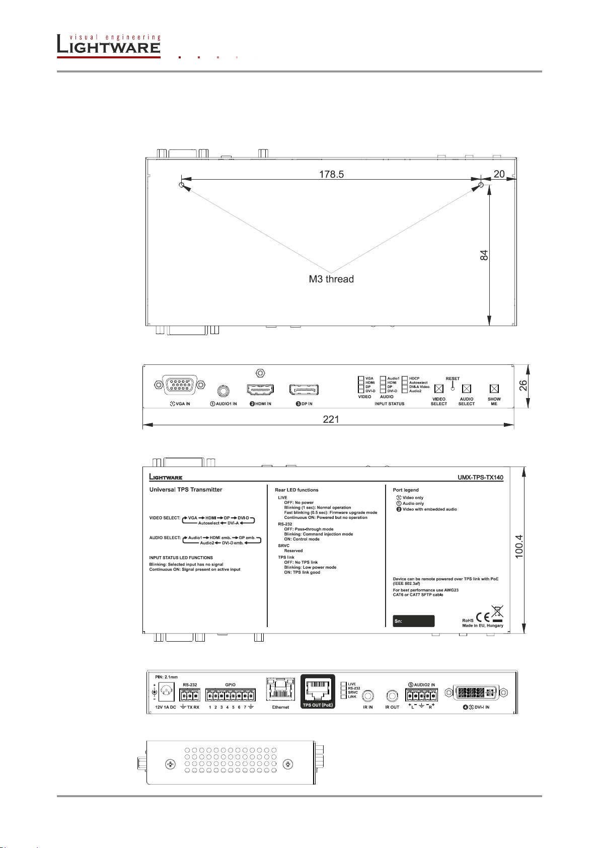
9.1. Mechanical drawings
UMX-TPS-TX140 can be seen on the pictures, but the dimensions are the same for all the
three models. Dimensions are in mm.
Bottom view
Front view
Top view
Rear view
Side view
Page 86 / 92 Section 9. Specifications
Page 87

Resolution
Pixel
clock rate
Cable lengths ( Auto / LR TPS mode)
CAT5e
AWG24
CAT7
AWG26**
CAT7
AWG23
1024x768@60Hz
65 MHz
100 m / 130 m*
90 m / 120 m*
120 m / 170 m*
1280x720p@60Hz
73.8 MHz
100 m / 130 m*
90 m / 120 m*
120 m / 170 m*
1920x1080p@60Hz / 24bpp
148.5 MHz
100 m / 130 m*
90 m / 120 m*
120 m / 170 m*
1920x1200@60Hz
152.9 MHz
100 m / NA
90 m / NA
120 m / NA
1600x1200@60Hz
162 MHz
100 m / NA
90 m / NA
120 m / NA
1920x1080@60Hz / 36bpp
223.6 MHz
70 m / NA
70 m / NA
100 m / NA
3840x2160@30Hz UHD ***
297 MHz
70 m / NA
70 m / NA
100 m / NA
4096x2160@30Hz 4K ***
297 MHz
70 m / NA
70 m / NA
100 m / NA
Parameter
Setting/Value
Network settings
IP address
192.168.0.100
Subnet mask
255.255.255.0
Static gateway
192.168.0.1
LW2 Port number
10001
LW3 Port number
6107
HTTP Port number
80
DHCP
disabled
Crosspoint settings
Video input
VGA input
Audio input
Audio 1 input
Autoselect
Disabled, Priority detect, No change
Video port settings
Analog video source (VGA, DVI-A)
Auto
HDCP (DP, HDMI, DVI-D)
Enabled
No sync screen mode
Auto
No sync screen color
RGB: 0x7F;0x7F;0x7F
No sync screen resolution
640x480
Output TPS mode
Auto
Output HDMI mode
Auto
Output Color space
Auto
Output HDCP
Auto
Audio port settings
Volume
0.00 dB
Balance
50
9.2. Maximum twisted pair distances
* Valid with longreach TPS mode. Longreach TPS mode supports pixel clock frequencies
up to 148.5 MHz.
** Distances are 20% shorter if remote powering used. AWG 26 cables are not
recommended with remote powering.
UMX-TPS-TX100 series
User’s Manual
*** If 4K video is selected to the output, analog audio cannot be embedded to the video
stream due to the capabilities of the video IC, thus the original audio stream will be
transmitted.
9.3. Factory default settings
Section 9. Specifications Page 87 / 92
Page 88

Emulated EDIDs
VGA input
F89 – Univ_Analog
HDMI input
F119 – Univ_4k_All
DP input
F119 – Univ_4k_All
DVI-D input
F119 – Univ_4k_All
DVI-A input
F89 – Univ_Analog
Dynamic
F119 – Univ_4k_All
RS-232 and GPIO settings
Control protocol
LW2
Baud rate
57600
Databits
8
Parity
No
Stopbits
1
Operation mode (Local)
Pass-through
Operation mode (Link)
Pass-through
GPIO direction
Input
GPIO output level
High
Page 88 / 92 Section 9. Specifications
Page 89

Mem.
Resolution
Type
Mem.
Resolution
Type
F01
640 x 480 @ 60 Hz
D
F61
1280 x 768 @ 59.92 Hz
A
F02
848 x 480 @ 60.0 Hz
D
F62
1280 x 768 @ 75.0 Hz
A
F03
800 x 600 @ 60.30 Hz
D
F63
1360 x 768 @ 60.1 Hz
A
F04
1024 x 768 @ 60.0 Hz
D
F64
1364 x 768 @ 50.0 Hz
A
F05
1280 x 768 @ 50.0 Hz
D
F65
1364 x 768 @ 59.93 Hz
A
F06
1280 x 768 @ 59.92 Hz
D
F66
1364 x 768 @ 74.98 Hz
A
F07
1280 x 768 @ 75.0 Hz
D
F67
1280 x 1024 @ 50.0 Hz
A
F08
1360 x 768 @ 60.1 Hz
D
F68
1280 x 1024 @ 60.1 Hz
A
F09
1280 x 1024 @ 50.0 Hz
D
F69
1366 x 1024 @ 59.99 Hz
A
F10
1280 x 1024 @ 60.1 Hz
D
F70
1400 x 1050 @ 49.99 Hz
A
F11
1280 x 1024 @ 75.1 Hz
D
F71
1400 x 1050 @ 59.99 Hz
A
F12
1400 x 1050 @ 49.99 Hz
D
F72
1400 x 1050 @ 75.0 Hz
A
F13
1400 x 1050 @ 59.99 Hz
D
F73
1920 x 540 @ 50.0 Hz
A
F14
1400 x 1050 @ 75.0 Hz
D
F74
1920 x 540 @ 59.98 Hz
A
F15
1680 x 1050 @ 59.99 Hz
D
F75
1920 x 1080 @ 50.0 Hz
A
F16
1920 x 1080 @ 50.0 Hz
D
F76
1920 x 1080 @ 60.0 Hz
A
F17
1920 x 1080 @ 60.0 Hz
D
F77
1600 x 1200 @ 50.0 Hz
A
F18
2048 x 1080 @ 50.0 Hz
D
F78
1600 x 1200 @ 60.0 Hz
A
F19
2048 x 1080 @ 59.99 Hz
D
F79
1920 x 1200 @ 59.55 Hz
A
F20
1600 x 1200 @ 50.0 Hz
D
F80
1920 x 1200 @ 50.0 Hz
A
F21
1600 x 1200 @ 60.0 Hz
D
F81
Reserved
F22
1920 x 1200 @ 50.0 Hz
D
F82
Reserved
F23
1920 x 1200 @ 59.55 Hz
D
F83
Reserved
F24
2048 x 1200 @ 59.95 Hz
D
F84
Reserved
F25
Reserved
F85
Reserved
F26
Reserved
F86
Reserved
F27
Reserved
F87
Reserved
F28
Reserved
F88
Reserved
F29
Universal_DVI
D
F89
Univ_Analog
A
F30
1440 x 240i @ 60.3 Hz
H
F90
1920 x 2160 @ 59.98 Hz
DL
F31
1440 x 288i @ 50.6 Hz
H
F91
1024 x 2400 @ 60.1 Hz
DL
F32
640 x 480 @ 59.94 Hz
H
F92
1920 x 2400 @ 59.97 Hz
DL
F33
720 x 480 @ 59.92 Hz
H
F93
2048 x 2400 @ 59.97 Hz
DL
F34
720 x 576 @ 50.0 Hz
H
F94
2048 x 1536 @ 59.99 Hz
DL
F35
1280 x 720 @ 50.0 Hz
H
F95
2048 x 1536 @ 74.99 Hz
DL
F36
1280 x 720 @ 60.0 Hz
H
F96
2560 x 1600 @ 59.85 Hz
DL
F37
1920 x 540i @ 50.3 Hz
H
F97
3840 x 2400 @ 23.99 Hz
DL
F38
1920 x 540i @ 50.0 Hz
H
F98
1280 x 720 @ 60.0 Hz
H3D
F39
1920 x 540i @ 59.98 Hz
H
F99
1920 x 1080 @ 60.0 Hz
H3D
F40
1920 x 540i @ 60.5 Hz
H
F100
1024 x 768 @ 60.0 Hz
H
F41
1920 x 1080 @ 24.0 Hz
H
F101
1280 x 1024 @ 50.0 Hz
H
F42
1920 x 1080 @ 24.99 Hz
H
F102
1280 x 1024 @ 60.1 Hz
H
F43
1920 x 1080 @ 30.0 Hz
H
F103
1280 x 1024 @ 75.1 Hz
H
F44
1920 x 1080 @ 50.0 Hz
H
F104
1600 x 1200 @ 50.0 Hz
H
F45
1920 x 1080 @ 59.93 Hz
H
F105
1600 x 1200 @ 60.0 Hz
H
F46
1920 x 1080 @ 60.0 Hz
H
F106
1920 x 1200 @ 59.55 Hz
H
F47
Universal_HDMI_PCM
H
F107
2560 x 1440 @ 59.94 Hz
H
F48
Universal_HDMI_ALL
H
F108
2560 x 1600 @ 59.85 Hz
H
F49
Universal_HDMI_DC
H
F109
3840 x 2400 @ 23.99 Hz
H4K
F50
720 x 480 @ 30.1 Hz
A
F110
3840 x 2160 @ 24.0 Hz
H4K
F51
720 x 576 @ 25.3 Hz
A
F111
3840 x 2160 @ 25.0 Hz
H4K
F52
640 x 480 @ 60.0 Hz
A
F112
3840 x 2160 @ 30.0 Hz
H4K
F53
640 x 480 @ 75.0 Hz
A
F113
Reserved
F54
800 x 600 @ 50.0 Hz
A
F114
Reserved
F55
800 x 600 @ 60.3 Hz
A
F115
Reserved
F56
800 x 600 @ 74.99 Hz
A
F116
Reserved
F57
1024 x 768 @ 49.98 Hz
A
F117
Reserved
F58
1024 x 768 @ 60.0 Hz
A
F118
Universal_4K_PCM
H4K
F59
1024 x 768 @ 75.2 Hz
A
F119
Universal_4K_ALL
H4K
F60
1280 x 768 @ 50.0 Hz
A
EDID types: D=DVI EDID; H=HDMI EDID; A=Analog EDID; DL=Dual-Link DVI EDID;
H3D=HDMI EDID with 3D support; H4K: HDMI EDID with 4K resolution support
9.4. Factory EDID list
UMX-TPS-TX100 series
User’s Manual
Section 9. Specifications Page 89 / 92
Page 90
Video port
Port nr. (LW2)
Port nr. (LW3)
Emulated EDID memory
VGA video in
I1
P1
E1
HDMI video in
I2
P2
E2
Video out
O1
P3
-
Audio port
Port nr. (LW2)
Port nr. (LW3)
Audio1 in
I1
P1
HDMI audio in
I2
P2
Audio out
O1
P3
Video port
Port nr. (LW2)
Port nr. (LW3)
Emulated EDID memory
VGA video in
I1
P1
E1
HDMI video in
I2
P2
E2
DVI-D video in
I3
P3
E3
DVI-A video in
I4
P4
E4
Test pattern
I5
P5
-
Video out
O1
P6
-
Audio port
Port nr. (LW2)
Port nr. (LW3)
Audio1 in
I1
P1
HDMI audio in
I2
P2
DVI-D audio in
I3
P3
Audio out
O4
P4
9.5. Input/output port numbering
Following tables contain the input and output ports with their ID numbers which shall be
used when protocol command sending or in Lightware Device Controller.
9.5.1. UMX-TPS-TX120
Table 7. Video input and output port numbering of UMX-TPS-TX120
Table 8. Audio input and output port numbering of UMX-TPS-TX120
9.5.2. UMX-TPS-TX130
Table 9. Video input and output port numbering of UMX-TPS-TX130
Page 90 / 92 Section 9. Specifications
Table 10. Audio input and output port numbering of UMX-TPS-TX130
Page 91

UMX-TPS-TX100 series
Video port
Port nr. (LW2)
Port nr. (LW3)
Emulated EDID memory
VGA video in
I1
P1
E1
HDMI video in
I2
P2
E2
DP video in
I3
P3
E3
DVI-D video in
I4
P4
E4
DVI-A video in
I5
P5
E5
Test pattern
I6
P6
-
Video out
O1
P7
-
Audio port
Port nr. (LW2)
Port nr. (LW3)
Audio1 in
I1
P1
HDMI audio in
I2
P2
DP audio in
I3
P3
DVI-D audio in
I4
P4
Audio 2 in
I5
P5
Audio out
O1
P6
User’s Manual
9.5.3. UMX-TPS-TX140
Table 11. Video input and output port numbering of UMX-TPS-TX140
Table 12. Audio input and output port numbering of UMX-TPS-TX140
Section 9. Specifications Page 91 / 92
Page 92
10. Version applicability
version
UMX-TPS-TX100 series firmware
1.0.0
Lightware Device Controller software
1.1.0
Document
Release Date
Changes
Editor
Rev. 1.0
26-09-2014
Initial version
Laszlo Zsedenyi
This User’s Manual applies to the following versions of the mentioned software, firmware
and hardware:
11. Warranty
Lightware Visual Engineering warrants this product against defects in materials and
workmanship for a period of three years from the date of purchase.
The customer shall pay shipping charges when unit is returned for repair. Lightware will
cover shipping charges for return shipments to customers.
In case of defect please call your local representative, or Lightware at
Lightware Visual Engineering
H-1071 Budapest, Peterdy Street 15, HUNGARY
E-mail: [email protected]
12. Document revision history
Page 92 / 92 Section 10. Version applicability
 Loading...