

Page 1

INSTALLATION AND
OPERATIONS
M
ANUAL
MULTISET PRO®- PRE-WIRED DIMMING CABINET MDC20
MULTISET PRO® - PRE-WIRED
DIMMING CABINET MDC20
Made in U.S.A.
For technical/sales assistance, call: 1-800-526-2731
www.lolcontrols.com
P/N 85-1530
I
MPORTANT: RETAIN THESE INSTRUCTIONS FOR THE END USER
. DO NOT DISCARD.
WARNING: Before installation, disconnect power at circuit breakers or remove fuse to avoid electrical
shock or damage to the unit. It is recommended that an electrician perform this installation.
COMPATIBLE WITH MULTISET PRO® HEATSINK DIMMER MODELS:
MHP5ES, MHP8ES, MPH5AVES, MHP8AVES, MHP600VA, MHP1000VA, MHP1500VA,
MHP2000VA, MHP1000ND, MHP2000ND, MHP500QE, MHP600HDF120,
MHP1500HDF120, MHP600EB, MHP1000EB, MHP1500EB, MHPWHIS
ABCD
1
2
3
4
5
Page 2

CAUTION: Be sure that power to the load being controlled is disconnected by removing fuse or turning circuit breaker off. Installing
MultiSet Pro® dimmers or Masters with power on may expose you to dangerous voltage and damage the device. A qualified electrician
should perform this installation.
2
MULTISET PRO®- PRE-WIRED DIMMING CABINET MDC20
Installation
and Operation
The MultiSet Pro® is a revolutionary system of advanced digital wallbox dimmers for economical and flexible multi-scene, multi-channel control. MultiSet Pro® provides flexible 13-scene preset dimming control for up to 30 devices, as well as, 12 adjustable fade rates
up to one hour that are programmable by scene.
The MultiSet Pro® Pre-Wired Dimmer Cabinet MDC20 facilitates design and installation by combining dimmers and controls into a common enclosure. Each cabinet is shipped assembled, pre-wired, and tested with its dimmers and/or master stations. The cabinet arrives at
the job site ready to accept power and load wiring from the installer. This can significantly reduce installation time and potential wiring
issues while providing a clean and consistent installation. For design flexibility, the cabinet accommodates several load types and device
ratings. To best suit the application, the designer indicates where each device is located within the cabinet.
MultiSet Pro® Pre-Wired Dimmer Cabinet MDC20 is a U.L./c.U.L. listed enclosure designed to hold up to 20 MultiSet Pro® dimmers
and masters, which can be configured into one or more individual rooms. Maximum wattage capacity is 20 dimmers at 1000W each (total
20,000 watts) or 10 dimmers at 1920W each (total 19,200 watts). For higher capacity applications, multiple cabinets (MHPWDC20,
MDC20, MDC56) may be wired together.
Note: A single MultiSet Pro® System (purple wire network) can accommodate up to 30 MultiSet Pro® dimmers and masters.
When the total number of MultiSet Pro® devices exceeds the 30-device limit, use the dimming cabinet to accommodate one or more [30
devices] MultiSet Pro® Dimming Systems. Blank plates are provided to cover all unused spaces. The dimmer cabinet is surface or recess
wall mounted. All dimmers and components are serviceable or removable from the front of the cabinet. The cabinet features a doublehinged, lockable latching cover. The cover is made from heavy gauge steel which prevents tampering of the devices.
The MDC20 Cabinet features air vents to maintain proper air flow through the dimmers. The cabinet shall insure satisfactory operation
of the equipment within an ambient temperature range of 0° to 40° C. (No cooling fans are used.)
For applications that require rough in prior to the dimmers being installed, order the MultiSet Pro® Cabinet Enclosure (MDC20ENC) and
Cabinet Interior (MDC20INT). (See 87-0573 MDC20 Product Specification Sheet.)
Description
Entrance into the line voltage wiring section is through the double-hinged front cover of the cabinet. Provide a separate neutral connection for all loads (no common neutrals). If normal power is lost, the dimmers will retain their presets and will return to their last state
when power is restored.
Note: Each dimmer is fed from an individual circuit breaker. (See Typical Wiring Diagram on page 7.)
Wiring
1. All MultiSet Pro® devices require a neutral connection (no common neutrals). Each circuit-feeding dimmers and dimmed loads
require a separate neutral. Shared neutrals will result in undesirable flashing of controlled loads.
2. Use VA dimmers to control incandescent, low-voltage with magnetic transformers, neon, cold cathode, or general inductive loads.
When calculating a magnetic low-voltage load, a 25% transformer loss must be factored (i.e. actual lamp wattage plus 25% equals
total load).
3. Use Quiet Electronic (QE) Dimmers to control only low-voltage fixtures that have electronic, solid-state transformers, and regular
incandescent loads. Not for use with Magnetic Low Voltage fixtures.
4. Use HDF Direct Drive Dimmers to control fluorescent lighting loads at 120V with approved Lightolier® Controls PowerSpec®
HDF Electronic Ballasts only, and Lightolier® Controls Dimming Amplifiers.
5. Use Electronic Ballast (EB) Direct Drive Dimmers to control Advance Mark 10® Dimmable Electronic Ballast.
6. MultiSet Pro® Dimmers or Switches may be fed individually or in groups, regardless of phase.
7. MultiSet Pro® Masters draw approximately one watt and may be fed through any circuit. Multiple masters may be interconnected.
The total number of dimmers and masters are not to exceed 30. An unlimited number of channel remotes (MSCR) may be used.
8. HDF Dimmers can be connected to a Dimming Amplifier. Please consult interface and amplifier instructions for wiring. Non-dim
switches can be connected to MultiSet Pro® relay modules for 277V loads.
9. Line voltage must not be supplied by a GFI breaker.
Caution
Read Before Beginning Installation
Page 3

MULTISET PRO®- PRE-WIRED DIMMING CABINET MDC20
Installation
and Operation
3
Cabinet Installation
1. Anchor mounts (Figure 1)
2. Terminal blocks (Figure 2)
3. Ground terminal strip
4. Dimmer mounting panel
5. Cabinet latch
6. Door and door frame
Note: No common neutrals
Features
Each Cabinet Cover has a swinging radius of 21"
1. Surface or recess mount on wall using appropriate
wall anchors. Use wall anchors capable of supporting up to 80-90 pounds.
Note: All wiring should be in accordance with local
regulations and the National Electrical Code. All
wiring shall enter and exit the cabinet via the provided
knock outs at the top or bottom of the cabinet.
2. Terminate 120VAC lines and neutrals to terminal
blocks. Do not use common neutrals
3. Connect lighting loads to the load terminal block.
Be sure to match proper load with the correct
device (refer to device location sticker on front of
cabinet).
4. Connect ground to dimming cabinet.
5. Connect network "purple" wire to additional cabinets (when necessary).
Figure 1
Figure 2
BACK
1
1
5
Detail C
6
Dimmer
Detail C
4
FRONT
1
1
2
Terminal Blocks
3
3
(see descriptions below)
Enclosure::
- Can be ordered separately for
rough - in.
Order part number: MDC20ENC
Interior:
2
- Terminal Blocks
- Mounting Back Plane
- Dimmer(s) Mounting Panel
- Door and Door Frame
- Can be ordered separately and
installs int o MDC20ENC
Order part number: MDC20INT*
*Requires part numb er MDC20ENC
Terminal Blocks:
Installed and positioned according to dimmer/master
configuration for each cabinet.
- Red Terminal Blocks: Load wire terminations
- Black Terminal Blocks: Power feed terminations
- Blue Terminal Block: MultiSet Pro purple wire terminations
- White Terminal Block: Neutral wire terminations
- Grey Terminal Block: Lightolier Controls PowerSpec HDF
dimming ballast TAN wire termination.
Page 4
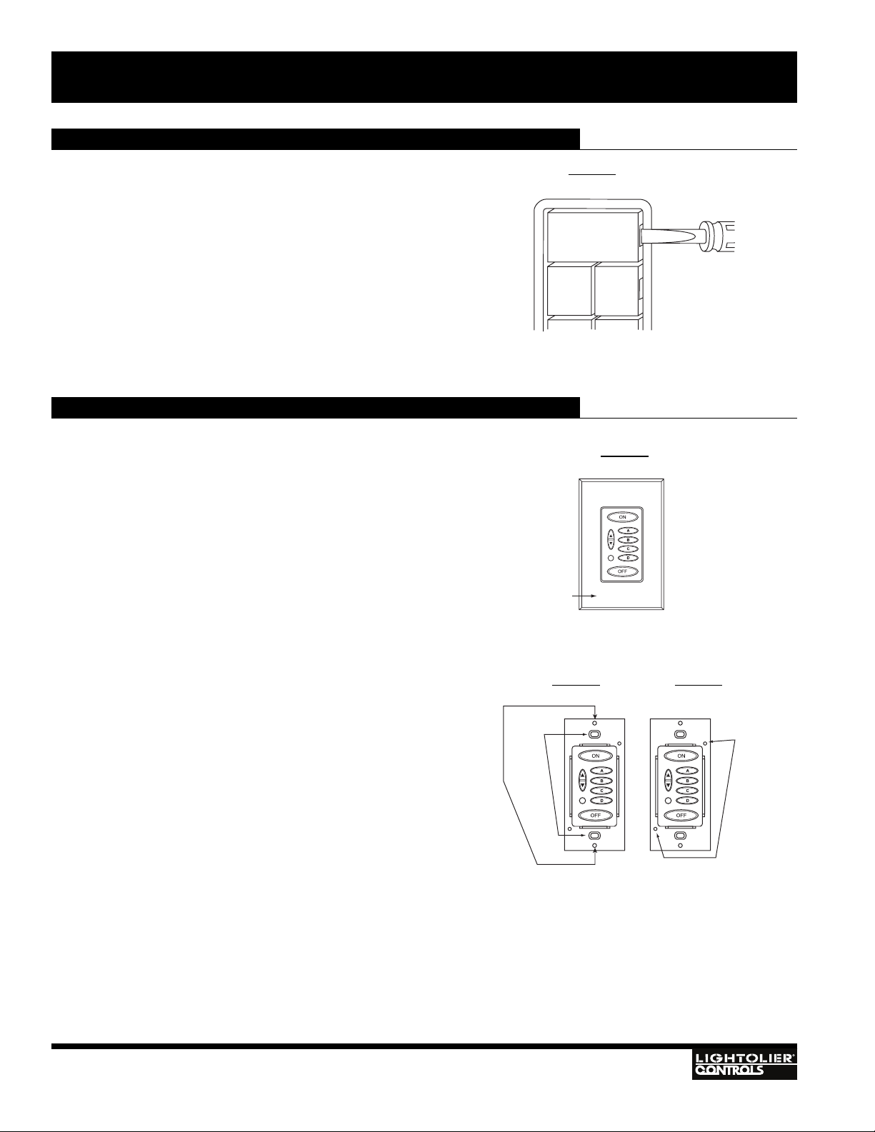
Replacing the Keypad Button Labels (Classic Series)
MultiSet Pro® Classic Series Masters are supplied with over 260
labels to personalize the buttons for your own scene names. The
buttons are labeled at the factory with letters. These button labels
can easily be changed to customize your system:
1. Insert a small screwdriver into the outside edge on the side
of a button and pry off the plastic key cover.
CAUTION: Pry from outside edge, do not attempt to insert
screwdriver between key covers (Figure 3).
2. Remove the factory label and insert an appropriate label
from the supplied label sheet into the key cover.
3. Snap the cover over the button housing by pressing firmly
on the plastic key cover.
4. Repeat for each button you wish to change.
Replacing the Keypad Membrane (Ellipse Series)
The overlay on these models is easily replaced, even if the unit is
currently installed.
1. Turn the power off at the circuit breaker.
2. Remove the faceplate (Figure 4).
3. Remove the master keypad wall screws (Figure 5).
3a. On heatsink model, remove heatsink screws and spacers
(Figure 5).
4. Remove the retaining plate screws and plate (Figure 6).
5. Remove the existing keypad membrane.
6. Install the new keypad membrane, being careful to line it up
properly with the openings.
7. Reinstall the retaining plate and screws (Figure 6).
7a. On heatsink model, reinstall screws and spacers (Figure 5).
8. Reinstall the master keypad to wallbox (Figure 5).
9. Reinstall the faceplate (Figure 4).
10.Turn the power back on at the circuit breaker.
Note: Spacers on the heatsink model are not attached to the unit.
4
Figure 3
Figure 4
Figure 5 Figure 6
MULTISET PRO®- PRE-WIRED DIMMING CABINET MDC20
Installation
and Operation
Faceplate
Wall
Screws
ON
A
B
Screws
Heatsink
Screws
Page 5

5
Dimmer/Switch Operating Instructions
MULTISET PRO® DIMMER
• To Turn light on to preset level, tap top of rocker, the dimmer fades up at the 1.5 second rate.
• A second tap of the rocker fades the dimmer to full brightness.
• To adjust the light level, press and hold top or bottom of rocker until desired light level is reached, and then release.
• To turn lights off, tap the bottom of the rocker. The dimmer fades at the 3 second fade rate.
• To quickly return to the preset level when light is on, quickly tap OFF and then ON. The lights adjust to the preset level.
• To bypass the fade rate and turn the lights to full ON or OFF, double tap the dimmer for ON or OFF.
• If the Master is in the OFF scene, the Master ON button illuminates when any dimmer is turned on.
• To change the preset level of the current scene:
• Press and hold the rocker until lights reach the desired level then release.
• Press the small set button next to the switch to save the preset in memory.
LEDs on the MultiSet Pro® Dimmer/Switch indicate status:
1. Red LED is on when Dimmer/Switch is off to locate Dimmer/Switch when room is dark.
2. As many as 3 green LEDs may be illuminated at any given time. The bright green LED
indicates the current level of the dimmer. The medium green LED indicates the preset level
of the current scene. The dim green LED indicates the preset level of the ON scene.
MULTISET PRO® UNIVERSAL ELECTRONIC SWITCH (NON-DIM)
The MultiSet Pro® Universal Electronic Switch can be programmed as a four or five-scene nondim switch. When programmed as a five-scene device, it is not suitable for 3-way applications.
The default mode of the switch is as a normal (4-scene) non-dim device. The AV (5-scene) mode allows the non-dim switch to remain
off when the master ON button is pressed.
To change the mode of the switch:
1. Tap OFF on the Master to place the switch in the OFF scene.
2. Press and hold the SET button. After 3 Seconds, a green LED illuminates on the bargraph. If the switch is currently in normal
mode, the bottom green LED illuminates. If it is in AV mode, the top LED illuminates.
3. Tap the top of the rocker once to toggle the mode.
4. Release the SET button.
Note: In normal mode, a “soft start” feature is utilized to extend bulb life. In AV mode, the “soft start” feature is not
implemented.
After you have completed installation of all the MultiSet Pro® devices and have
energized the system, each scene can be programmed.
1. Tap the preset button (ON, A - L) on the MultiSet Pro® Master that you wish to
program (see Step 1, Figure 8).
2. Adjust each MultiSet Pro® Dimmer to the desired intensity and the MultiSet Pro®
Switches to either ON or OFF (see above).
3. Press the Set button on each device (see Step 3, pg. 7) after all devices have been
adjusted.
Repeat Steps 1-3 until all scenes have been programmed.
Programming Scenes
Figure 7
Figure 8
MULTISET PRO®- PRE-WIRED DIMMING CABINET MDC20
Installation
and Operation
Red LED
Green LED
Set
Button
Step 1
Preset
Buttons
(ON, A, B
C, D)
F E
H
G
I
L K
Preset
Buttons
J
(E-L)
Page 6

6
Changing the Fade Rate
MultiSet Pro® Dimmers can be programmed for 12 different fade rates. Dimmers
can be programmed to have a different fade rate on each scene.
The fade rate choices are:
1.5 seconds 1 minute
3 seconds 2 minutes
4.5 seconds 5 minutes
7.5 seconds 15 minutes
15 seconds 30 minutes
30 seconds 60 minutes
Global Fade Rate = One fade rate for all scenes.
Each dimmer’s fade rate affects all scenes. Examples: Dimmer #1 fade rate set 7.5 sec.,
dimmer #2 set to 15 sec., and dimmer #3 set to 3 sec. When any scene is selected dimmers #1, 2, and 3, will respond with 7.5, 15, and 3 seconds, respectively for ON, OFF,
A, B, C, D, E, F, G, H, I J, K, and L.
To change the Global Fade Rate that affects all scenes:
1. Tap the OFF button on the Master.
2. Press and hold the SET button. After 3 seconds, either a single green LED or a
pair of green LEDs indicates the current “global” fade rate. The bottom LED indicates the 1.5 second fade rate, the next LED up is 3 seconds, while the top LED is
2 minutes. If the bottom two LEDs are on, it indicates the 5 minutes fade rate, if
the next two LEDs up are lit, it indicates 15 minutes, while the top two LEDs
indicate the 60 minute fade rate.
Note: When the two LEDs are on, they will not be at the same intensity.
3. While holding the Set button, tap the top of the rocker to sequence the LEDs
through the various fade rates until the desired fade rate is selected.
4. Release the SET button.
5. Repeat steps 2 - 4 for each device.
To change the fade rate that will affect only an individual scene:
1. Tap a scene button on the Master to go to a scene.
2. Press and hold the SET button.
3. After 3 seconds, either a single green LED or a pair of green LEDs indicates the
scene’s fade rate.
4. While holding the SET button, tap the top rocker until the desired fade rate is
reached.
5. Release the SET button.
6. Repeat above for each scene.
M
ULTI
SET PRO® MASTER (CLASSIC SERIES)
• Tap the ON button to elegantly illuminate the entire area to the ON “preset”.
• Press and hold the ON button to brighten lighting level.
• Tap the OFF button to fade lights to OFF.
• Press and hold OFF button to lower lighting level.
• Tap a scene button to access “preset” light levels.
• Two quick taps of any button (including ON and OFF) will fade lighting quickly.
MULTISET PRO® MASTER (ELLIPSE SERIES)
• Press or Tap the ON button to elegantly illuminate the entire area to the ON “preset”.
• Press the RAISE button to brighten lighting level.
• Tap the OFF button to fade lights to OFF.
• Press LOWER button to lower lighting level.
• Tap a scene button to access one of the “preset” light levels.
• Two quick taps of any button (except RAISE or LOWER) will fade lighting quickly.
Figure 9
Figure 10
Operating Instructions
MULTISET PRO®- PRE-WIRED DIMMING CABINET MDC20
Installation
and Operation
Figure 12
Figure 11
Step 1
Press and hold Set
button for 3 seconds.
Step 2
Tap top of dimmer paddle
to increment fade rate.
Step 3
Release Set button.
2 min
1 min
30 sec
15 sec
7.5 sec
4.5 sec
3 sec
1.5 sec
“Green”
LED Lights
60 min
30 min
15 min
5 min
Raise/Lower
Button
Built-in IR
Receiver
All-On
A
B
CD
Off
ON
OFF
Classic Series
Ellipse Series
Page 7

Setting the Button Brightness (Ellipse Series)
The brightness level of each Ellipse Master Control Station button can be programmed to 100% (factory default), 75%, 50%, or 25%.
To change the setting:
1. On a 5-Scene Master, press and hold buttons “B” and “D” simultaneously for 3 seconds (on an 8Scene Master, press buttons “H” and “J”). On a 5-Scene Master, buttons “A” thru “D” illuminate
(on an 8-Scene Master, buttons “G” thru “J” illuminate). The blinking LED displays the current
LED brightness setting. The continuously-illuminated LEDs display the available brightness settings that can be selected.
2. To change the brightness setting, press the button illuminated at the desired brightness. This button
will begin blinking.
3. To save the selected brightness and exit the mode, press the ON button on a 5-Scene Master (or the
“E” button on an 8-Scene Master). All buttons on that master will now have the new brightness setting.
7
Connecting Multiple Cabinets
Up to 30 MultiSet Pro® Devices may be controlled as one system.
Figure 13
Figure 14
Figure 15
Typical Wiring Diagram
MULTISET PRO®- PRE-WIRED DIMMING CABINET MDC20
Installation
and Operation
See Page 3 for Terminal Block
Wiring Descriptions.
Note: No Common Neutrals
on Dimmed Circuits.
Note: Knockouts are provided
on top and both sides.
5-Scene
Master
8-Scene
Master
LED
Brightness
%001GA
%57HB
%05IC
%52JD
(One dimmed 120VAC Line / Neutral per circuit)
To Lighting Loads
MDC20
ABCD
1
2
3
4
5
MHPWDC20
MHPWDC20
ABCD
1
2
3
4
5
Up to 20 Circuits...
120VAC Line / Neutral
120VAC Line / Neutral
120VAC Line / Neutral
120VAC Line / Neutral
120VAC Line / Neutral
120VAC Line / Neutral
120VAC Line / Neutral
120VAC Line / Neutral
120VAC Line / Neutral
120VAC Line / Neutral
120VAC Line / Neutral
120VAC Line / Neutral
120VAC Line / Neutral
120VAC Line / Neutral
120VAC Line / Neutral
120VAC Line / Neutral
120VAC Line / Neutral
120VAC Line / Neutral
120VAC Line / Neutral
120VAC Line / Neutral
MDC20
ABCD
1
2
3
4
5
Circuit Breaker Panel
MDC20
ABCD
1
2
3
4
5
Purple Wire
Purple Wire
Page 8

Lightolier®Controls
A Genlyte Company
10911 Petal Street • Dallas, Texas 75238
This product may be covered by one or more of the following U.S. Patents: #4,413,211; 4,430,576; 4,465,956; 4,733,138; 4,792,731; 4,880,950; 4,988,840; 4,992,709; 5,004,969; 5,004,969;
5,128,654; 5,153,816; 5,189,259; 5,194,858; 5,239,255; 5,239,255; 5,371,439; 5,371,444; 5,506,480; 5,636,111; 5,642,104; 5,646,490; 5,814,550; 5,821,704; 5,920,156; 5,930,126; Des.
#307,578; 333,124; 435,203; 440,207; License #4482844; 5,004,969; 5,239,255; and corresponding foreign patents. Other Utility, Design and Foreign Patents Pending. We reserve the right
to change details of design, materials and finish in any way that will not alter the installed appearance or reduce function performance. Specifications are subject to change without notice.
Lightolier®Controls
A Genlyte Company
10911 Petal Street • Dallas, Texas 75238
For technical/sales assistance, call: 1-800-526-2731
Made in U.S.A. ©Lightolier®Controls 2006
www.lolcontrols.com
P/N 85-1530
Cabinet Specifications
Dimensions
Note: Cabinet cover has a swinging radius of 21"
3 YEAR LIMITED WARRANTY
Lightolier® Controls warrants that this product will be free from defects in workmanship or materials. This warranty is void
on any electronic controls which have been overloaded, abused, improperly installed or altered in any manner.
Lightolier Controls’ sole obligation will be at its option to repair or replace any electronic controls product proven defective
if it is returned, postage prepaid, to Lightolier Controls, 10911 Petal St. Dallas, Texas 75238. Lightolier Controls will not pay
for any charge-back or charge for labor or material that does not have its prior written approval.
This warranty shall be in lieu of any other warranty, express or implied, including but not limited to any implied warranty
of merchantability or fitness for a particular purpose. Some states do not allow limitations on how long an implied warranty lasts and do not allow the exclusion or limitation of incidental or consequential damages, so the above limitation or exclusions may not apply to you. This warranty gives you specific legal rights, and you may also have other rights, which vary
from state to state.
MULTISET PRO®- PRE-WIRED DIMMING CABINET MDC20
Installation
and Operation
Input Voltage: 108-132VAC, 60Hz, ±3Hz
Operating Temperature: 0°- 40° Celsius
Weight: 80 lbs empty - 88 lbs with (20) 1000W dimmers
Dimensions: 45.5"(H) x 20.1"(W) x 5.5"(D)
Materials: White, 16 Gauge Steel
Enclosure: Double hinged cover / lockable latching cover
20.1"
18.0"
4.0"
1.5"
45.5" 45.5"
 Loading...