

Page 1
Lightolier
45 INDUSTRIAL WAY, WILMINGTON, MA 01887
ULM MODULE MOTION OR DAYLIGHT SENSOR ENCLOSURE INSTALLATION INSTRUCTIONS
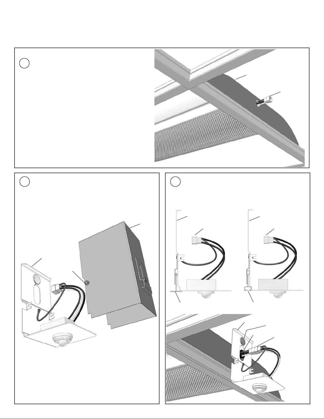
Install the fixture. The Electrical Connector for
the Module must be accessible through the
1
knockout at the end of the Fixture prior to the
Module being installed.
Fixture
Electrical
Connector
REMOVE COVER
2
Remove the Cover from the Module by loosening
the 2 Screws.
Module
Screw
Cover
MOUNTING AND ELECTRICAL CONNECTIONS
3
Mount Module to T-Bar, mate Electrical
Connections, install Bushing and install 7/8" Plug
if necessary.
Module
Electrical
Connectors
T-Bar (G)
Module
T-Bar (T)
Module
7/8" Plug
Bushing
Electrical
Connectors
Electrical
Connectors
© Lightolier 2006 59-31159-000 Printed in U.S.A.
Page 2
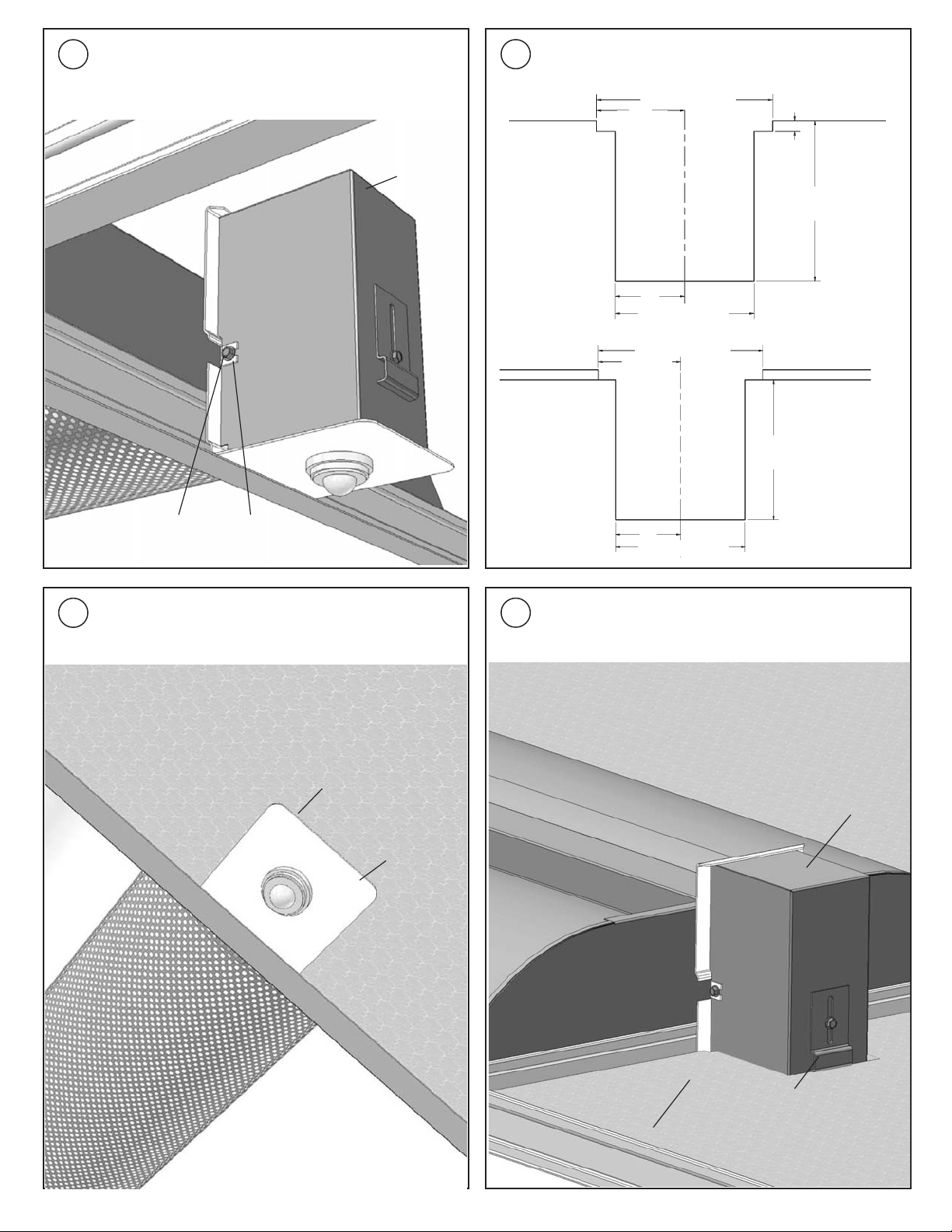
ATTACH COVER
4
Attach Cover by sliding the Screws from the Cover
over the two Tabs and fasten securely.
Cover
DIMENSIONS TO CUT TILE
5
Cut Ceiling Tile in the center using the dimensions
below.
4-1/8" (105mm)
2-1/16"
(52mm)
1/4"
(6mm)
3-3/4"
(95mm)
Screw
TILE
6
Install cut Ceiling Tile.
Tab
1-5/8" (29mm)
3-1/4" (89mm)
4-1/8" (105mm)
2-1/16"
(52mm)
1-5/8" (29mm)
HD CLIP
7
Adjust HD Clip to ensure Module Fascia sits flush
3-1/4" (89mm)
G-Type Tile
3-1/2"
(89mm)
T-Type Tile
Slot Grid
to Ceiling Tile. Installation is complete.
Cut
Ceiling
Tile
Module
Fascia
Ceiling
Tile
Module
HD Clip
 Loading...