

Lighting Systems Baselyte-BSL25
Page 1 of 7 1 Light T5 HO Indirect
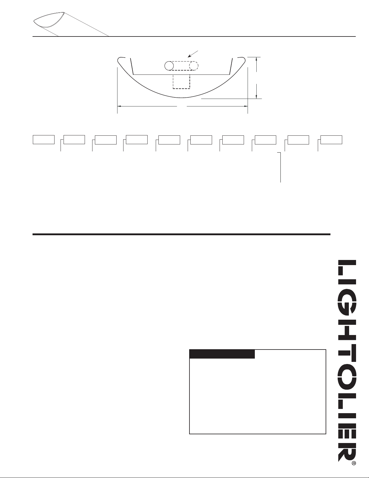
angled lamp
Weight = 3.0 lb./ft
Ordering Information
Family
BSL
Distribution
3
3 = Indirect
Lamp Type
H
H = T5 HO
No. of Lamps
01
01 = 1 Light
Housing
EN
EN = Solid 04 = 4’
Module Length
08 = 8’
12 = 12’
Wiring
1 = 1cct.
3 = 1cct.
w/EC/NL
5 = 1cct.
w/EM Battery
7 = 1cct.
w/Dimming
8 = 1cct. w/1cct.
Thru wire
Note: Please
consult wiring
section of spec
sheets for more
wiring options.
Voltage
D = Dual 120V
& 277V
1 = 120V
2 = 277V
Note: Option‘D’ is
standard. Voltage
options 1 and 2 are
only available with
EM Battery and
Dimming wiring
options.
Ballast Finish
E = Standard
<10% THD
F = Standard
<10% THD
w/fusing
C = Custom Color
W = Standard
White
Specifications
Features
1. Housing: die-formed 20ga. cold rolled steel
2. End Set: die-cast metal with baked powder coat finish
3. Lamping: one T5 HO lamp
4. Configuration: 4’, 8’ and 12’ module lengths or continuous rows
5. Ballasts: electronic 120V or 277V
Finish
High-quality white powder coat with textured matte finish.
Custom colors available. Consult factory.
Mounting
Aircraft cable gripper is tamper-resistant and provides infinite vertical
adjustment capability. Aircraft cable, crimp and cable gripper independently
tested to meet stringent safety requirements.
Electrical
All luminaires are factory pre-wired to module ends with quick-wire
connectors.
Joints & Intersections
Self-aligning joining system with hands-free pre-joining wire access.
Labels
UL, CSA standards.
Ordering Instructions
Individual Fixtures
1. Determine the number of individual modules required
2. Order one end set per module
3. Order one non-power mount per module
4. Order one power mount per module
Continuous Rows*
1. Determine run length
2. Order the appropriate number and length of modules for complete run
3. Order one end set for each run
4. Order one non-power mount for each module
5. Order one power mount per run
6. Order one joiner per module minus one (e.g. 3 modules requires 2 joiners)
*Note: Some runs may require additional power mounts. Please see the
‘Run Configuration’ table on the next page for more details.
Job Information
Job Name:
Cat. No.:
Lamp(s):
Notes:
Type:
Lightolier a Genlyte Company www.lightolier.com
631 Airport Road, Fall River, MA 02720 • (508) 679-8131 • Fax (508) 674-4710
We reserve the right to change details of design, materials and finish.
© 2005 Genlyte Group LLC • 0205 Rev.1
Lighting Systems Baselyte-BSL25
-ODULE,ENGTH
-OUNTING$ISTANCE
-ODULE,ENGTH-OUNTING$ISTANCE
-ODULE,ENGTH-OUNTING$ISTANCE
@
@
@
CANDLEPOWER SUMMARY
ZONE CANDLEPOWER
DEG. 0 22.5 45 67.5 90
180 1078 1078 1078 1078 1078
175 1073 1073 1077 1080 1081
165 1035 1042 1064 1079 1086
155 963 980 1032 1073 1090
145 860 892 985 1057 1083
135 721 786 925 1031 1070
125 564 667 857 998 1051
115 385 546 792 946 1001
105 197 435 647 691 754
95 35 165 156 80 109
90 2 3 7 3 7
85 0 0 0 0 0
75 0 0 0 0 0
65 0 0 0 0 0
55 0 0 0 0 0
45 0 0 0 0 0
35 0 0 0 0 0
25 0 0 0 0 0
15 0 0 0 0 0
5 0 0 0 0 0
0 0 0 0 0 0
COEFFICIENTS OF UTILIZATION
% EFFECTIVE CEILING CAVITY REFLECTANCE
80 70 50
% WALL REFLECTANCE
50 30 10 50 30 10 50 30 10
0 90 90 90 77 77 77 52 52 52
1 78 74 71 66 64 61 45 44 42
2 68 62 58 58 54 50 40 37 35
3 59 53 48 51 46 42 35 32 29
4 52 45 40 45 39 35 31 27 24
5 46 39 34 40 34 29 27 23 21
6 41 34 29 35 29 25 24 20 18
7 37 30 25 31 26 22 22 18 15
8 33 26 22 28 23 19 19 16 13
9 30 23 19 26 20 16 18 14 11
10 27 21 17 23 18 14 16 12 10
COEFFICIENTS OF UTILIZATION
% EFFECTIVE CEILING CAVITY REFLECTANCE
80 70 50
% WALL REFLECTANCE
ZONAL LUMEN SUMMARY
ZONE LUMENS % BARE LAMP %LUMINAIRE
0-90
90-180
0-180
4413
4413
0 0
100.0
100.0
0
94.9
94.9
Page 2 of 7 1 Light T5 HO Indirect
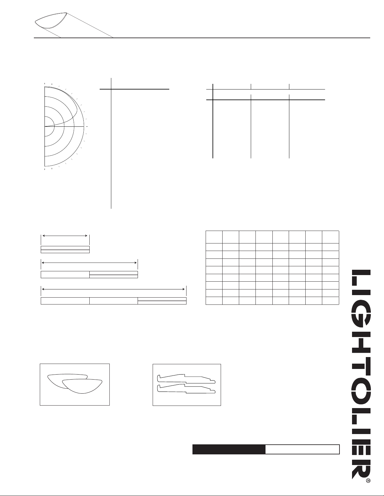
Performance
Candlepower Curve Candlepower Summary Coefficients of Utilization
Report No: 2101709
Lamps: F54T5
Lumens per Lamp: 4650
Efficiency: 94.9%
Up: 100.0% Down: 0.0%
Module Lengths & Mounting Distances
Note: Shaded area indicates locations of emergency sections (emergency wiring
controls all lamps or optional battery pack controls one or two lamps).
System Components & Accessories
End Set
BSLESW = suspended standard white
Joiner
BSLJS = suspended joiner
Job Information Type:
Lightolier a Genlyte Company www.lightolier.com
631 Airport Road, Fall River, MA 02720 • (508) 679-8131 • Fax (508) 674-4710
We reserve the right to change details of design, materials and finish.
© 2005 Genlyte Group LLC • 0205 Rev.1
Zonal Lumen Summary
ZONE LUMENS %BARE LAMP %LUMINAIRE
Run Configuration
Run
Length
4’ run 1 1 1 1
8’ run 1 1 1 1
12’ run
16’ run
20’ run 1 1 1 1 2 1
24’ run 2 1 1 2 1
28’ run 2 1 2 1 3 1
32’ run 1 2 2 1 3 1
*Note: Additional power mounts may be required for some runs with T5 HO
lamping options, longer runs, and runs with wiring options that are more complex.
Please consult factory for assistance.
4’
Module8’Module
12’
Joiner End Set Mount
Module
1 1 1 1
2 1 1 2 1
Power
Mount*
Lighting Systems Baselyte-BSL25
Page 3 of 7 1 Light T5 HO Indirect
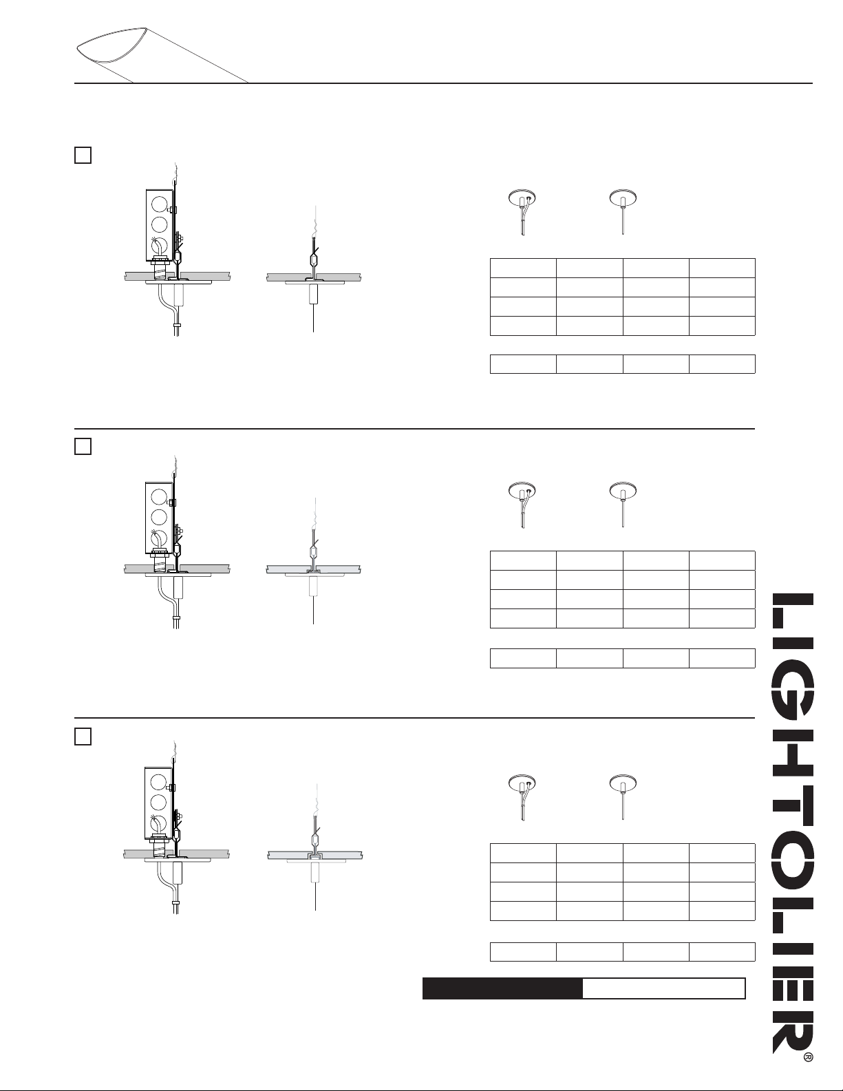
Mounting Options
Mount Type: T-Bar 15/16” (On-Grid)*
Non-Power Mount1-Power Mount
Supension Length
2’ 4’ 8’ 12’
BSLM6102P13 BSLM6104P13 BSLM6108P13 BSLM6112P13
BSLM6102P14 BSLM6104P14 BSLM6108P14 BSLM6112P14
BSLM6102P17 BSLM6104P17 BSLM6108P17 BSLM6112P17
BSLM6102N BSLM6104N BSLM6108N BSLM6112N
• 65 lbs maximum load
• Canopy: Diameter of 3 3/4“x 7/32”
• Cable: 7x7 stranded aircraft cable
• Supported by T-bar and secured to structure
• J-Box: 4” square (supplied by others)
• Fully adjustable vertically at fixture
Mount Type: T-Bar 9/16” (On-Grid)*
1-Power Mount
3 Conductor
4 Conductor
7 Conductor
Non-Power Mount
• 65 lbs maximum load
• Canopy: Diameter of 3 3/4“x 7/32”
• Cable: 7x7 stranded aircraft cable
• Supported by T-bar and secured to structure
• J-Box: 4” square (supplied by others)
• Fully adjustable vertically at fixture
Mount Type: T-Bar 9/16” by 5/16” Slot Grid (On-Grid)*
• 65 lbs maximum load
• Canopy: Diameter of 3 3/4“x 7/32”
• Cable: 7x7 stranded aircraft cable
• Supported by T-bar and secured to structure
• J-Box: 4” square (supplied by others)
• Fully adjustable vertically at fixture
*Note: Standard T-bar mounts are currently not available for tegular tile ceilings,
however
slot-grid mount. For more information, please consult factory.
certain tegular tile / T-bar combinations may be supported by the use of the
Non-Power Mount1-Power Mount
Supension Length
1-Power Mount
3 Conductor
4 Conductor
7 Conductor
Non-Power Mount
2’ 4’ 8’ 12’
BSLM6202P13 BSLM6204P13 BSLM6208P13 BSLM6212P13
BSLM6202P14 BSLM6204P14 BSLM6208P14 BSLM6212P14
BSLM6202P17 BSLM6204P17 BSLM6208P17 BSLM6212P17
BSLM6202N BSLM6204N BSLM6208N BSLM6212N
Non-Power Mount1-Power Mount
Supension Length
1-Power Mount
3 Conductor
4 Conductor
7 Conductor
Non-Power Mount
2’ 4’ 8’ 12’
BSLM6302P13 BSLM6304P13 BSLM6308P13 BSLM6312P13
BSLM6302P14 BSLM6304P14 BSLM6308P14 BSLM6312P14
BSLM6302P17 BSLM6304P17 BSLM6308P17 BSLM6312P17
BSLM6302N BSLM6304N BSLM6308N BSLM6312N
Job Information Type:
Lightolier a Genlyte Company www.lightolier.com
631 Airport Road, Fall River, MA 02720 • (508) 679-8131 • Fax (508) 674-4710
We reserve the right to change details of design, materials and finish.
© 2005 Genlyte Group LLC • 0205 Rev.1

Lighting Systems Baselyte-BSL25
Page 4 of 7 1 Light T5 HO Indirect
Mount Type: T-Bar Fixed Position (1/4-20 Threaded Rod)
Non-Power Mount1-Power Mount 2-Power Mount
Supension Length
2’ 4’ 8’ 12’
BSLM2102P13 BSLM2104P13 BSLM2108P13 BSLM2112P13
BSLM2102P14 BSLM2104P14 BSLM2108P14 BSLM2112P14
BSLM2102P23 BSLM2104P23 BSLM2108P23 BSLM2112P23
BSLM2102N BSLM2104N BSLM2108N BSLM2112N
Non-Power Mount1-Power Mount 2-Power Mount
• Meets UBC, OSHPD and DSA seismic requirements
• Canopy: Diameter of 5 1/4“x 3/4” (power)
• Cable: 7x7 stranded aircraft cable
• Tile cut-out hole: Diameter of 2 1/2” (power) or 3/4” (non-power)
• J-Box: Integral J-Box supplied
• 1/4 - 20 all thread rod (supplied by others)
• Fully vertically adjustable at fixture
Mount Type: T-Bar Variable Position
1-Power Mount
3 Conductor
4 Conductor
2-Power Mount
3 Conductor
Non-Power Mount
• Meets UBC, OSHPD and DSA seismic requirements
• Canopy: Diameter of 3“x 7/32”
• Cable: 7x7 stranded aircraft cable
• Tile cut-out hole: Diameter of 2 1/4”
• Aligned by T-bar and secured to structure
• J-Box 4” square (supplied by others)
• Fully vertically adjustable at fixture
• Adjusts to both 1” and 1 1/2” high T-bar systems
*Note: Supports 15/16”, 9/16” and slot grid ceiling types.
Mount Type: Support or Open-Joist Ceiling
• Meets UBC, OSHPD and DSA seismic requirements
1/4
• Canopy: Diameter of 5
• Cable: 7x7 stranded aircraft cable
• Versatile mount, fully adjustable to accomodate open sloped ceilings
• J-Box: 4” octogonal box (supplied by others)
• Fully vertically adjustable at fixture
“x
3/4
”(power)
Supension Length
1-Power Mount
3 Conductor
4 Conductor
7 Conductor
2-Power Mount
3 Conductor
Non-Power Mount
2’ 4’ 8’ 12’
BSLM5102P13 BSLM5104P13 BSLM5108P13 BSLM5112P13
BSLM5102P14 BSLM5104P14 BSLM5108P14 BSLM5112P14
BSLM5102P17 BSLM5104P17 BSLM5108P17 BSLM5112P17
BSLM5102P23 BSLM5104P23 BSLM5108P23 BSLM5112P23
BSLM5102N BSLM5104N BSLM5108N BSLM5112N
Non-Power Mount1-Power Mount 2-Power Mount
Supension Length
1-Power Mount
3 Conductor
4 Conductor
7 Conductor
2-Power Mount
3 Conductor
Non-Power Mount
2’ 4’ 8’ 12’
BSLM3102P13 BSLM3104P13 BSLM3108P13 BSLM3112P13
BSLM3102P14 BSLM3104P14 BSLM3108P14 BSLM3112P14
BSLM3102P17 BSLM3104P17 BSLM3108P17 BSLM3112P17
BSLM3102P23 BSLM3104P23 BSLM3108P23 BSLM3112P23
BSLM3102N BSLM3104N BSLM3108N BSLM3112N
Job Information Type:
Lightolier a Genlyte Company www.lightolier.com
631 Airport Road, Fall River, MA 02720 • (508) 679-8131 • Fax (508) 674-4710
We reserve the right to change details of design, materials and finish.
© 2005 Genlyte Group LLC • 0205 Rev.1

Lighting Systems Baselyte-BSL25
Page 5 of 7 1 Light T5 HO Indirect
Mount Type: Non-Accessible Ceilings (concrete, gypsum etc.)
Non-Power Mount1-Power Mount 2-Power Mount
Supension Length
2’ 4’ 8’ 12’
BSLM1102P13 BSLM1104P13 BSLM1108P13 BSLM1112P13
BSLM1102P14 BSLM1104P14 BSLM1108P14 BSLM1112P14
BSLM1102P17 BSLM1104P17 BSLM1108P17 BSLM1112P17
BSLM1102P23 BSLM1104P23 BSLM1108P23 BSLM1112P23
BSLM1102N BSLM1104N BSLM1108N BSLM1112N
• Meets UBC, OSHPD and DSA seismic requirements
• Canopy: Diameter of 5
• Cable: 7x7 stranded aircraft cable
• Mountable on 0º - 15º sloped ceiling
• Optional Chicago Plenum approved version available (A4)
• J-Box: 4” octogonal box (supplied by others)
• Fully vertically adjustable at fixture
1/4
“x
3/4
” (power)
Cord Types
1-Power Mount
3 Conductor
4 Conductor
7 Conductor
2-Power Mount
3 Conductor
Non-Power Mount
3 Conductor
• Max. 10 amps
• Max. 300V
4 Conductor
• Max. 10 amps in a 1 circuit application
• Max. 5 amps per circuit in a 2 circuit application
• Max. 300V
• Good for 2 circuit feeds or a 1 circuit feed with
a battery pack hot lead
• 120V or 277V applications
7 Conductor
• Max. 10 amps in a 1 circuit application
• Max. 5 amps per circuit in a multi-circuit
application
• Good for 3 circuit feeds or 2 circuit feeds with a
battery pack hot lead
• 120V or 277V applications
Job Information Type:
Lightolier a Genlyte Company www.lightolier.com
631 Airport Road, Fall River, MA 02720 • (508) 679-8131 • Fax (508) 674-4710
We reserve the right to change details of design, materials and finish.
© 2005 Genlyte Group LLC • 0205 Rev.1

Lighting Systems Baselyte-BSL25
%#.,
%-
�
�
%#.,%-
Page 6 of 7 1 Light T5 HO Indirect
Wiring Options: 1 Circuit
1 Circuit
Type 1: 1cct.
Type 8: 1cct. w/1cct. thru wire
Type H: 1cct. w/2cct. thru wire
Type 7: 1cct. w/dimming
1 Circuit with Emergency Circuit/Night Light (EC/NL)
Type 3: 1cct. w/EC/NL
All lamps wired on one circuit.
One 4’ section in a one circuit fixture to be wired on a separate thru circuit. Leads for both normal
circuit and EC/NL circuit wired to fixture ends. All lamps in EC/NL section to be wired together.
1 Circuit with Emergency Battery Pack (EM)
Type 5: Chloride standard
CTP700
Type M: Bodine standard
LP550
Type E: Chloride high performance
CTP1300
Type P: Bodine high performance
LP600
1 Circuit with Emergency Circuit/Night Light and Emergency Battery Pack
Type J: Chloride standard
CTP700
All lamps wired on one circuit, plus a battery pack is wired to one lamp. A hot lead is connected
to the battery pack and would function as a ‘trigger’ wire when connected to a constant hot by
installer. Leads for both normal circuit and battery pack are wired to fixture ends.
One 4’ section in a one circuit fixture to be wired on a separate thru circuit, in addition, a battery
pack is wired to one lamp. Installer can connect ‘trigger’ wire to EC hot lead if controlled together
or wire separately if controlled independently. Leads for normal circuit, EC/NL circuit and EM wired
to fixture ends. All lamps in EC/NL section to be wired together.
Job Information Type:
Lightolier a Genlyte Company www.lightolier.com
631 Airport Road, Fall River, MA 02720 • (508) 679-8131 • Fax (508) 674-4710
We reserve the right to change details of design, materials and finish.
© 2005 Genlyte Group LLC • 0205 Rev.1

Lighting Systems Baselyte-BSL25
%-
%#.,%-
%#.,
Page 7 of 7 1 Light T5 HO Indirect
Wiring Options: 2 Circuit A/B Switching (alternate 4’ sections)
2 Circuit A/B Switching (alternate 4’ sections)
Type B: 2cct.
Type A: 2cct. w/1cct. thru wire
Type S: 2cct. w/2cct. thru wire
Fixture wired for two circuit. Lamps wired for A/B switching in alternate 4’ sections.
2 Circuit A/B Switching (alternate 4’ sections) with Emergency Circuit/Night Light (EC/NL)
Type C: 2cct. w/EC/NL
One 4’ section in a two circuit fixture (A/B switching) to be wired on a separate thru circuit. Leads
for both normal circuit and EC/NL circuit wired to fixture ends.
2 Circuit A/B Switching (alternate 4’ sections) with Emergency Battery Pack (EM)
Type D: Chloride standard
CTP700
Type O: Bodine standard
LP550
Type G: Chloride high performance
CTP1300
Type R: Bodine high performance
LP600
2 Circuit A/B Switching (alternate 4’ sections) with Emergency Circuit/Night Light and Emergency Battery Pack
Type L: Chloride standard
CTP700
Fixture wired for two circuits (A/B switching), plus a battery pack is wired to one lamp. A hot lead
is connected to the battery pack and would act as a ‘trigger’ wire when connected to a constant hot
by installer. Leads for both normal circuit and battery pack are wired to fixture ends.
One 4’ section in a two circuit fixture (A/B switching) to be wired on a separate thru circuit, in
addition, a battery pack is wired to one lamp. Installer can connect ‘trigger’ wire to EC hot lead if
controlled together or wired separately if controlled independently. Leads for normal circuit, EC/NL
circuit and battery pack are wired to fixture ends. All lamps in EC/NL module to be wired together.
Job Information Type:
Lightolier a Genlyte Company www.lightolier.com
631 Airport Road, Fall River, MA 02720 • (508) 679-8131 • Fax (508) 674-4710
We reserve the right to change details of design, materials and finish.
© 2005 Genlyte Group LLC • 0205 Rev.1
 Loading...