

Page 1
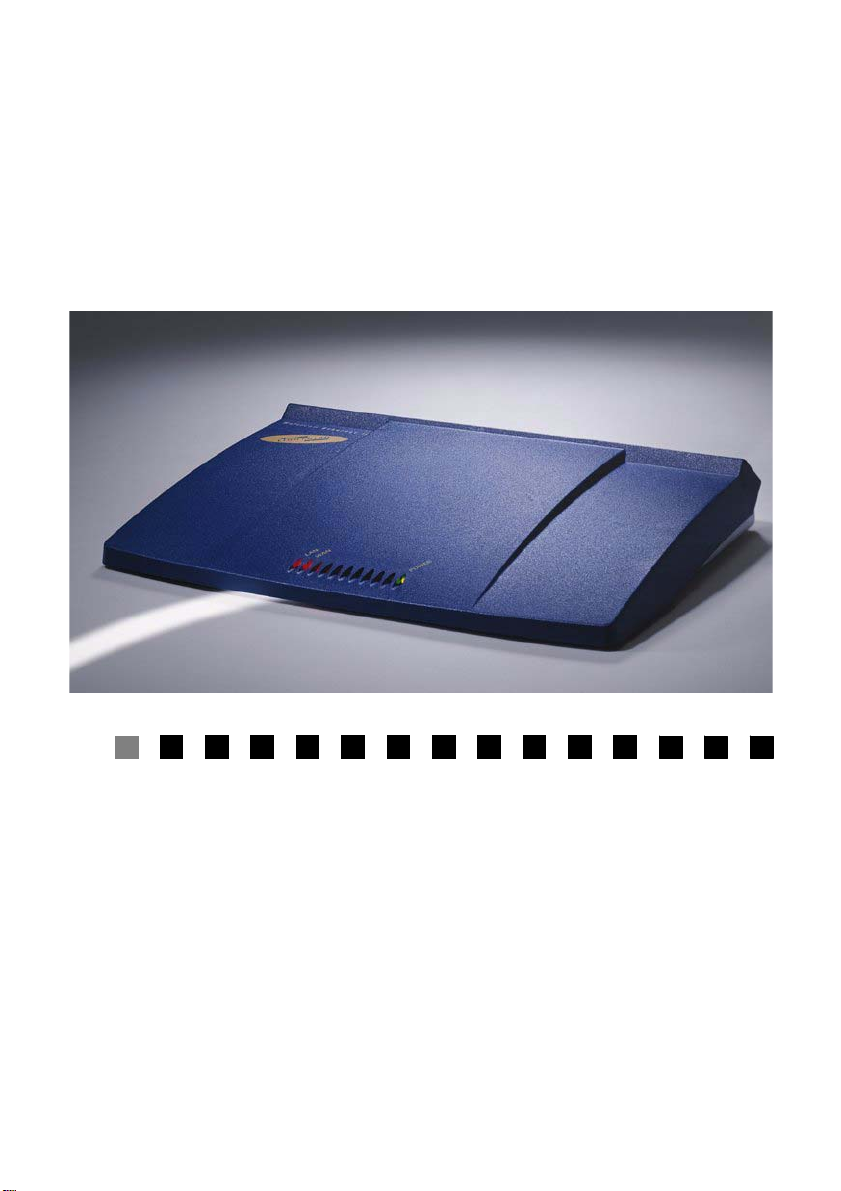
MultiCom Firewall
User's Manual
For Firmware 3.7 -10/19/04
Page 2

ii MultiCom Firewall User’s Manual
Page 3

User's Manual
Copyright © 2004 Lightning SA and Apliware SA. All Rights Reserv ed. No pa rt
of this document may be reproduced in any forms by any means without the prior
written consent of Apliware SA.
LIGHTNING Instrumentation SA
Avenue des Boveresses 50
Lausanne, Vaud 1010
Switzerland
Phone +41.21.654.2000
Fax +41.21.654.2001
http://www.lightning.ch
APLIWARE SA
rue du Grand-Pré 70
1222 Geneva 2
Switzerland
Phone +41.22.918.3610
Fax +41.22.918.3695
http://www.apliware.com
MultiCom Firewall User’s Manual iii
Page 4

iv MultiCom Firewall User’s Manual
Page 5

Copyright, Warranty, Liability
Copyright, Warranty,
Liability
Copyright
The technical information in this
document is proprietary to
LIGHNTING S.A. and APLIWARE
S.A. and the recipient has a personal,
non-exclusive and non-transferable
license to use this information solely
with the use of LIGHNTING S.A.
and APLIWARE S.A. products.
The information in this document is
subject to change without notice.
Revisions may be issued at any time.
Trademarks
MultiCom and Lightning are
registered trademarks of
LIGHTNING Instrumentation SA.
Stac LZS and Hi/fn are registered
trademarks of Hi/fn, Inc. All other
company, brand and product names
may be registered trademarks or
trademarks of their respective
companies and are hereby
recognized.
Revisions
This publication and the information
herein is furnished AS IS, subject to
change without notice, and should
not be construed as a commitment by
LIGHNTING S.A. and APLIWARE
S.A. Furthermore, LIGHNTING
S.A. and APLIWARE S.A. assumes
no responsibility or liability for any
errors or inaccuracies, makes no
warranty of any kind (express,
implied or statutory) with respect to
this publication, and expressly
disclaims any and all warranties of
merchantability, fitness for particular
purposes and noninfringement of
third-party right.
Warranty
NO WARRANTIES ARE
EXTENDED BY THIS
DOCUMENT. The only product
warranties made by LIGHNTING
S.A. and APLIWARE S.A., if any,
are set forth in the agreed terms and
MultiCom Firewall User’s Manual v
Page 6

Chapter Copyright, Warranty, Liability
conditions for the purchase of
LIGHNTING S.A. and APLIWARE
S.A. products. LIGHNTING S.A.
and APLIWARE S.A. declaims
liability for any and all direct and
indirect damages that may result
from publication or use of this
document and/or its contents.
LIGHNTING S.A. and APLIWARE
S.A. warrants all hardware products
of its manufacture to be free from
defects in material and workmanship
for 12 months from date of delivery.
Upon prompt notification by the
purchaser, LIGHNTING S.A. and
APLIWARE S.A. will correct,
within the warranty period, any
defects in equipment of its
manufacture either by repair at its
factory or by supply of replacement
parts to the purchaser.
LIGHNTING S.A. and APLIWARE
S.A. must decide to its own
satisfaction that the equipment is
defective and has not developed
malfunctions as a result of misuse,
modification, or abnormal conditions
of operation. Damages due to over
voltage (e.g. lightning strokes) or
wrong cabling on any interface are
expressly excluded from the
warranty. Opening the products also
voids the warranty. LIGHNTING
S.A. and APLIWARE S.A. assumes
no liability for consequential
damages, and its liability shall in no
case exceed the original purchase
price of the equipment.
The warranties set forth above are
the sole warranties applicable to
LIGHNTING S.A. and APLIWARE
S.A. products. THE IMPLIED
WARRANTY OF
MERCHANTABILITY AND ALL
OTHER WARRANTIES, EXPRESS
OR IMPLIED, ARE EXCLUDED.
Limitation of Liability
UNDER NO CIRCUMSTANCES,
INCLUDING NEGLIGENCE,
SHALL LIGHNTING S.A. AND
APLIWARE S.A. BE LIABLE FOR
LOSS OF USE, INTERRUPTION
OF BUSINESS, OR ANY
INDIRECT, SPECIAL,
INCIDENTAL, OR
CONSEQUENTIAL DAMAGES
OF ANY KIND (INCLUDING
LOST PROFITS) REGARDLESS
OF THE FORM OF ACTION
WHETHER IN CONTRACT, TORT
(INCLUDING NEGLIGENCE),
STRICT PRODUCT LIABILITY
OR OTHERWISE, EVEN IF
LIGHNTING S.A. AND
APLIWARE S.A. HAS BEEN
ADVISED OF THE POSSIBILITY
OF SUCH DAMAGES.
In no event shall LIGHNTING S.A.
and APLIWARE S.A. be liable for
costs of procurement of substitute
goods. The potential liability of
LIGHNTING S.A. and APLIWARE
S.A. arising out of this product is in
vi MultiCom Firewall User’s Manual
Page 7

Software and Documentation License
any case limited to the purchase
price paid to LIGHNTING S.A. and
APLIWARE S.A. for its products.
Software and Documentation
License
The software and documentation
included in or with products of
LIGHNTING S.A. and APLIWARE
S.A. is subject to following licence.
Third-Party Software. A part of the
software used within the MultiCom
Ethernet series can be freely
distributed under the terms of the
GNU Public License and BSD
copyright. However, some
applications remain the property of
their owners, and require their
permission to redistribute. For a
complete listing of the software used
within the MultiCom Firewall, and
the terms under which it can be
distributed, refer to the LIGHTNING
Web site at http://www.lightning.ch/
and to the Appendix on Additional
Licenses and Copyrights.
Shareware and Freeware Software.
Your MultiCom Companion CD
contains shareware, freeware and
other 3rd Party software not
developed by LIGHNTING S.A. and
APLIWARE S.A. Such software is
neither warranteed or supported by
LIGHNTING S.A. and APLIWARE
S.A. and is not necessary to use
LIGHNTING S.A. and APLIWARE
S.A. products. If you wish to use it
be sure to check that it meets your
company's standards for reliability,
security and useability. Please check
with the developer of the software
for any necessary information about
the use or capabilities of such
included software.
While all included software on this
CD has been virus checked and
tested LIGHNTING S.A. and
APLIWARE S.A. does not provide
any guarantees concerning these
products. Be sure to use any virus
protection that is required by your
company before using the included
software. If you go to a website of
these software developers be sure to
virus check any software that you
download from them before using it
as well.
LIGHNTING S.A. and APLIWARE
S.A. cannot accept responsibility for
any disruption, damage and/or loss to
your data or computer system that
may occur while using these
programs. If you are unsure about
what you are doing check with your
network administrator before
installing any software.
License. The software, on any media,
including disk, read-only memory,
and flash memory and the products
related documentation are licensed to
you by LIGHNTING S.A. and
APLIWARE S.A.. You own the
media on which the LIGHNTING
S.A. and APLIWARE S.A. software
is recorded, but LIGHNTING S.A.
and APLIWARE S.A. and/or
MultiCom Firewall User’s Manual vii
Page 8

Chapter Copyright, Warranty, Liability
LIGHNTING S.A. and APLIWARE
S.A.'s Licensor(s) retain title to the
LIGHNTING S.A. and APLIWARE
S.A. software and related
documentation. The license allows
you to use the LIGHNTING S.A.
and APLIWARE S.A. software on a
single LIGHNTING S.A. and
APLIWARE S.A. hardware product.
In the case of software on disk, you
are allowed to make one copy of
LIGHNTING S.A. and APLIWARE
S.A. software in machine-readable
form for backup purposes only. You
must reproduce on such copy the
LIGHNTING S.A. and APLIWARE
S.A. copyright notice and any other
proprietary legends that were on the
original copy of the disk containing
LIGHNTING S.A. and APLIWARE
S.A. software. You may also transfer
all your license rights in the
LIGHNTING S.A. and APLIWARE
S.A. software, together with the
associated hardware, the backup
copy, the related documentation, and
a copy of this license to another
party, provided the other party reads
and agrees to accept the terms and
conditions of this license.
Restrictions. The LIGHNTING S.A.
and APLIWARE S.A. software
contains copyrighted materials, trade
secrets, and other proprietary
materials and in order to protect
them you may not decompile,
reverse engineer, disassemble, or
otherwise reduce the LIGHNTING
S.A. and APLIWARE S.A. software
to a human-perceivable form. You
may not modify, network, rent, lease,
loan, distribute, or create derivative
works based upon the LIGHNTING
S.A. and APLIWARE S.A. software
in whole or in part. You may not
electronically transmit the
LIGHNTING S.A. and APLIWARE
S.A. software from one computer to
another or over a network.
Termination. This license is effective
until terminated. You may terminate
this license at any time by destroying
the LIGHNTING S.A. and
APLIWARE S.A. software, the
related hardware, related
documentation and all copies
thereof. The license will terminate
immediately without notice from
LIGHNTING S.A. and APLIWARE
S.A. if you fail to comply with any
provision of this license. Upon
termination you must destroy the
LIGHNTING S.A. and APLIWARE
S.A. software, the related hardware,
related documentation and all copies
thereof.
Limited Warranty on Media.
LIGHNTING S.A. and APLIWARE
S.A. warrants the media on which
the software is recorded as its
hardware materials, and limits the
liability as set for the hardware
material.
Disclaimer of warranty on
LIGHNTING S.A. and APLIWARE
S.A. software. You expressly
acknowledge and agree that use of
viii MultiCom Firewall User’s Manual
Page 9

Software and Documentation License
the LIGHNTING S.A. and
APLIWARE S.A. software is at your
sole risk. The LIGHNTING S.A. and
APLIWARE S.A. software and
related documentation are provided
"AS IS" and without warranty of any
kind and LIGHNTING S.A. and
APLIWARE S.A. EXPRESSLY
DISCLAIM ALL WARRANTIES,
EXPRESS OR IMPLIED,
INCLUDING, BUT NOT LIMITED
TO, THE IMPLIED WARRANTIES
OF MERCHANTABILITY AND
FITNESS FOR A PARTICULAR
PURPOSE. LIGHNTING S.A. AND
APLIWARE S.A. DOES NOT
WARRANT THAT THE
FUNCTIONS CONTAINED IN
THE LIGHNTING S.A. AND
APLIWARE S.A. SOFTWARE
WILL MEET YOUR
REQUIREMENTS, OR THAT THE
OPERATION OF THE
LIGHNTING S.A. AND
APLIWARE S.A. SOFTWARE
WILL BE UNINTERRUPTED OR
ERROR-FREE, OR THAT
DEFECTS IN THE LIGHNTING
S.A. AND APLIWARE S.A.
SOFTWARE WILL BE
CORRECTED. FURTHERMORE,
LIGHNTING S.A. AND
APLIWARE S.A. DOES NOT
WARRANT OR MAKE ANY
REPRESENTATIONS
REGARDING THE USE OR THE
RESULTS OF THE USE OF THE
LIGHNTING S.A. AND
APLIWARE S.A. SOFTWARE OR
RELATED DOCUMENTATION IN
THE TERMS OF THEIR
CORRECTNESS, ACCURACY,
RELIABILITY, OR OTHERWISE.
NO ORAL OR WRITTEN
INFORMATION OR ADVICE
GIVEN BY LIGHNTING S.A. AND
APLIWARE S.A. OR A
LIGHNTING S.A. AND
APLIWARE S.A.-AUTHORIZED
REPRESENTATIVE SHALL
CREATE A WARRANTY OR IN
ANY WAY INCREASE THE
SCOPE OF THIS WARRANTY.
SHOULD THE LIGHNTING S.A.
AND APLIWARE S.A.
SOFTWARE PROVE DEFECTIVE,
YOU (AND NOT LIGHNTING
S.A. AND APLIWARE S.A. OR A
LIGHNTING S.A. AND
APLIWARE S.A. AUTHORIZED
REPRESENTATIVE) ASSUME
THE ENTIRE COST OF ALL
NECESSARY SERVICING,
REPAIR, OR CORRECTION. Some
jurisdictions do not allow the
exclusion of implied warranties, so
the above exclusion may not apply to
you.
Limitation of Liability. Conforming
to the general limitation of liability.
Controlling Law and Severability.
This license shall be governed by
and construded in accordance with
the laws of Switzerland and Canton
de Vaud, as applied to agreements
entered into and to be performed
entirely between Canton de Vaud
residents. If for any reason a court of
competent jurisdiction finds any
MultiCom Firewall User’s Manual ix
Page 10

Chapter Copyright, Warranty, Liability
provision of this license, or portions
thereof, to be unenforceable, that
provision of the license shall be
enforced to the maximum extent
permissible so as to effect the intent
of the parties, and the remainder of
this license shall continue in full
force and effect.
Complete agreement. The license
constitutes the entire agreement
between the parties with respect to
the use of the LIGHNTING S.A. and
APLIWARE S.A. software and
related documentation, and
supersedes all prior or
contemporaneous understandings or
agreements, written or oral,
regarding such subject matter. No
amendment to or modification of the
License will be binding unless in
writing and signed by a duly
authorized representative of
LIGHNTING S.A. and APLIWARE
S.A..
with all such regulations and
acknowledges that it has the
responsibility to obtain licenses to
export, re-export, or import Software
and Hardware.
Export
Some versions and options of
LIGHNTING S.A. and APLIWARE
S.A.'s Software and Hardware,
including technical data, may be
subject to Swiss, E.U., U.S.
(including the U.S. Export
Administration Act) or other
countries export control laws, and
their associated regulations, and may
be subject to export or import
regulations in other countries.
Customer agrees to comply strictly
x MultiCom Firewall User’s Manual
Page 11

Contents
Copyright, Warranty, Liability . . . . . . . . . . . . . . . . . . . . . . . . . . . . . . v
Chapter 1 Preface . . . . . . . . . . . . . . . . . . . . . . . . . . . . . . . . . . . . . 17
Your New MultiCom Firewall. . . . . . . . . . . . . . . . . 17
MultiCom Firewall Features. . . . . . . . . . . . . . . . . . . 17
Options . . . . . . . . . . . . . . . . . . . . . . . . . . . . . . . . . . . 20
IPSec VPN Option . . . . . . . . . . . . . . . . . . . . . . . 21
SSH VPN Option . . . . . . . . . . . . . . . . . . . . . . . . 21
High Availability Option. . . . . . . . . . . . . . . . . . . 21
Network Monitoring Option . . . . . . . . . . . . . . . . 22
About This Manual. . . . . . . . . . . . . . . . . . . . . . . . . . 22
Conventions . . . . . . . . . . . . . . . . . . . . . . . . . . . . . . . 23
Packaging Contents . . . . . . . . . . . . . . . . . . . . . . . . . 24
If The Product Is Received Damaged. . . . . . . . . . . . 24
To Return The Product . . . . . . . . . . . . . . . . . . . . 24
Chapter 2 Introducing The MultiCom Firewalls . . . . . . . . . . . . 27
MultiCom Firewalls . . . . . . . . . . . . . . . . . . . . . . . . . 27
Introducing the Ethernet II . . . . . . . . . . . . . . . . . . . . 28
Back Panel. . . . . . . . . . . . . . . . . . . . . . . . . . . . . . 28
Front Panel of the Ethernet II . . . . . . . . . . . . . . . 29
Contents
MultiCom Firewall User’s Manual xi
Page 12

Introducing the Ethernet III . . . . . . . . . . . . . . . . . . . 30
Back Panel. . . . . . . . . . . . . . . . . . . . . . . . . . . . . . 30
Front Panel of the Ethernet III. . . . . . . . . . . . . . . 31
Introducing the MultiCom SpeedSurf . . . . . . . . . . . 32
Back Panel. . . . . . . . . . . . . . . . . . . . . . . . . . . . . . 32
Front Panel of the MultiCom SpeedSurf. . . . . . . 33
Introducing the Enterprise Ethernet . . . . . . . . . . . . . 34
Back Panel. . . . . . . . . . . . . . . . . . . . . . . . . . . . . . 34
Front Panel of the Enterprise Ethernet . . . . . . . . 35
Network Requirements. . . . . . . . . . . . . . . . . . . . . . . 36
Advanced Configuration Software Requirements . . 36
Safety Precautions . . . . . . . . . . . . . . . . . . . . . . . . . . 37
Chapter 3 Getting Started. . . . . . . . . . . . . . . . . . . . . . . . . . . . . . . 39
Connecting the MultiCom Firewall . . . . . . . . . . . . . 40
Configuring Your Computers. . . . . . . . . . . . . . . . . . 42
Windows . . . . . . . . . . . . . . . . . . . . . . . . . . . . . . . 43
Macintosh . . . . . . . . . . . . . . . . . . . . . . . . . . . . . . 46
Linux . . . . . . . . . . . . . . . . . . . . . . . . . . . . . . . . . . 48
Choosing the Internet Connection . . . . . . . . . . . . . . 48
Common Configurations. . . . . . . . . . . . . . . . . . . 48
Special Configurations . . . . . . . . . . . . . . . . . . . . 50
Configuration Checklist . . . . . . . . . . . . . . . . . . . 52
Plug & Play Configuration: DHCP . . . . . . . . . . . . . 54
Using the Easy Setup . . . . . . . . . . . . . . . . . . . . . . . . 55
Accessing the Easy Setup Web Server . . . . . . . . 56
WAN DHCP Easy Setup. . . . . . . . . . . . . . . . . . . 57
WAN PPPoE Easy Setup . . . . . . . . . . . . . . . . . . 58
WAN PPTP Easy Setup . . . . . . . . . . . . . . . . . . . 59
WAN Static IP Easy Setup . . . . . . . . . . . . . . . . . 61
LAN Easy Setup . . . . . . . . . . . . . . . . . . . . . . . . . 63
DMZ Easy Setup. . . . . . . . . . . . . . . . . . . . . . . . . 64
Easy Firewall Setup. . . . . . . . . . . . . . . . . . . . . . . 65
Saving The Configuration. . . . . . . . . . . . . . . . . . 66
Fine Tuning Your Configuration . . . . . . . . . . . . . . . 67
Activate Option Keys . . . . . . . . . . . . . . . . . . . . . 68
Configure Date And Time. . . . . . . . . . . . . . . . . . 68
Create New Privileged Administrator. . . . . . . . . 69
xii MultiCom Firewall User’s Manual
Page 13

Quick Interface Configuration . . . . . . . . . . . . . . 69
Testing Your Configuration . . . . . . . . . . . . . . . . . . . 70
Testing Security. . . . . . . . . . . . . . . . . . . . . . . . . . 71
Testing Connection Speed. . . . . . . . . . . . . . . . . . 72
Registering Your Firewall . . . . . . . . . . . . . . . . . . . . 72
Chapter 4 Maintenance. . . . . . . . . . . . . . . . . . . . . . . . . . . . . . . . . 73
Web Server Status Reports. . . . . . . . . . . . . . . . . . . . 74
Monitor Status Reports . . . . . . . . . . . . . . . . . . . . . . 76
Telnet/ Console Status Reports . . . . . . . . . . . . . . . . 79
Error Messages. . . . . . . . . . . . . . . . . . . . . . . . . . . . . 83
LED Light Messages. . . . . . . . . . . . . . . . . . . . . . 83
Syslog Messages . . . . . . . . . . . . . . . . . . . . . . . . . 84
SNMP Messages . . . . . . . . . . . . . . . . . . . . . . . . . 84
Configurator messages . . . . . . . . . . . . . . . . . . . . 85
Web Server Toolbox. . . . . . . . . . . . . . . . . . . . . . . . . 85
Web Server Advanced Tools . . . . . . . . . . . . . . . . . . 86
Backup Your Configuration. . . . . . . . . . . . . . . . . . . 87
Restoring A Configuration. . . . . . . . . . . . . . . . . . . . 88
Updating Your Firmware . . . . . . . . . . . . . . . . . . . . . 88
LED Status During Upgrade. . . . . . . . . . . . . . . . 92
Troubleshooting Firmware Upgrade. . . . . . . . . . 93
Chapter 5 Troubleshooting. . . . . . . . . . . . . . . . . . . . . . . . . . . . . . 95
Basic Things To Check . . . . . . . . . . . . . . . . . . . . . . 96
Common Local Network Problems . . . . . . . . . . . . . 97
DHCP Troubleshooting . . . . . . . . . . . . . . . . . . . . . . 98
DHCP To The Internet . . . . . . . . . . . . . . . . . . . . 98
DHCP On Your Local Network . . . . . . . . . . . . 100
PPPoE Troubleshooting . . . . . . . . . . . . . . . . . . . . . 101
Incorrect Password . . . . . . . . . . . . . . . . . . . . . . 102
PPPoE Server (ISP) Not Available . . . . . . . . . . 102
Some Web Sites Are Not Available . . . . . . . . . 102
Other Sources Of DSL Information . . . . . . . . . 103
PPTP Troubleshooting . . . . . . . . . . . . . . . . . . . . . . 104
Incorrect Password . . . . . . . . . . . . . . . . . . . . . . 104
PPTP Server Not Available. . . . . . . . . . . . . . . . 104
Incorrect IP configuration of WAN or LAN. . . 105
Resetting The Default Configuration . . . . . . . . . . . 105
MultiCom Firewall User’s Manual xiii
Page 14

Chapter 6 Frequently Asked Questions. . . . . . . . . . . . . . . . . . . 107
Frequently Asked Questions. . . . . . . . . . . . . . . . . . 107
Software, Shareware and Freeware . . . . . . . . . . . . 111
General Utilities . . . . . . . . . . . . . . . . . . . . . . . . 111
Windows . . . . . . . . . . . . . . . . . . . . . . . . . . . . . . 111
Macintosh OS Classic . . . . . . . . . . . . . . . . . . . . 112
Macintosh OSX. . . . . . . . . . . . . . . . . . . . . . . . . 113
Linux . . . . . . . . . . . . . . . . . . . . . . . . . . . . . . . . . 114
Appendix A Hardware Specifications. . . . . . . . . . . . . . . . . . . . . . 115
Ethernet II. . . . . . . . . . . . . . . . . . . . . . . . . . . . . . . . 116
Physical Specifications . . . . . . . . . . . . . . . . . . . 116
Declaration of Conformity . . . . . . . . . . . . . . . . 117
Ethernet III . . . . . . . . . . . . . . . . . . . . . . . . . . . . . . . 118
Physical Specifications . . . . . . . . . . . . . . . . . . . 118
Declaration of Conformity . . . . . . . . . . . . . . . . 119
MultiCom SpeedSurf . . . . . . . . . . . . . . . . . . . . . . . 120
Physical Specifications . . . . . . . . . . . . . . . . . . . 120
Declaration of Conformity . . . . . . . . . . . . . . . . 121
Enterprise Ethernet. . . . . . . . . . . . . . . . . . . . . . . . . 122
Physical Specifications . . . . . . . . . . . . . . . . . . . 122
Declaration of Conformity . . . . . . . . . . . . . . . . 123
Pin Assignments. . . . . . . . . . . . . . . . . . . . . . . . . . . 124
Appendix B Additional Licenses and Copyrights . . . . . . . . . . . . 125
Licensing . . . . . . . . . . . . . . . . . . . . . . . . . . . . . . . . 125
Apache License . . . . . . . . . . . . . . . . . . . . . . . . . 125
BSD Copyright . . . . . . . . . . . . . . . . . . . . . . . . . 125
GNU General Public License . . . . . . . . . . . . . . 127
OpenSSL License . . . . . . . . . . . . . . . . . . . . . . . 133
Original SSLeay License. . . . . . . . . . . . . . . . . . 135
TCPD License. . . . . . . . . . . . . . . . . . . . . . . . . . 136
Login License . . . . . . . . . . . . . . . . . . . . . . . . . . 137
Cryptix General License . . . . . . . . . . . . . . . . . . 137
PureTls License. . . . . . . . . . . . . . . . . . . . . . . . . 138
Copyrights . . . . . . . . . . . . . . . . . . . . . . . . . . . . . . . 139
BSD Copyright . . . . . . . . . . . . . . . . . . . . . . . . . 139
Glossary . . . . . . . . . . . . . . . . . . . . . . . . . . . . . . . . . . . . . . . . . . . . . . . 147
xiv MultiCom Firewall User’s Manual
Page 15

MultiCom Firewall User’s Manual xv
Page 16

xvi MultiCom Firewall User’s Manual
Page 17

Preface
Your New MultiCom Firewall
Congratulations on the purchase of your MultiCom Firewall. Your firewall ha s
been designed to offer security and high performance networking management,
all through an easy to use interface.
Whether you are connecting a single computer from home or managing a
company network you will find that the MultiCom Firewalls can help. You now
have access to many networking possibilities, for instance you can secure your
data, share your Internet connection with multiple computers and filter or receive
notifications of potential network attacks.
Chapter 1
For the latest release notes, documentation, firmware and software check the
Lightning website at http://www.lightning.ch/support.
MultiCom Firewall Features
Security
• Dual firewalls, using Stateful Packet Inspection (SPI) Filtering and/ or a NAT
based Firewall on each interface to protect against External Intrusions, Denial
MultiCom Firewall User’s Manual 17
Page 18

Chapter 1 Preface
of Service (DoS), Port Scanning, Spoofing Attacks and more
• URL Filtering to block or drop web connections based on URL or keywords.
• Intrusion Detection System (IDS) using SPI filtering & syslog
• Real time alerts and statistics using Syslog, SNMPv2, web-based Event
Monitor, email and more
• Up to 10 separate user accounts with passwords and access rights
• Secure SSL (HTTPS) & SSHv1-2 (telnet CLI) for remote access &
configuration
• DMZ interface support giving extra security for network servers (Ethernet III
and Enterprise Ethernet only)
Internet Access
• Connect multiple computers and ethernet devices to the Internet using
Internet Sharing using Network Address Translation (NAT)
• Easy Setup & Easy Firewall wizards via the web interface or the
multi-platform Configurator software
• DNS Cache for faster Internet response
• Dynamic DNS supporting 9 different services for finding your computer even
if the IP address changes
• Multimedia (H.323, IRC, ICQ) and PPTP client pass through support with
NAT
• DHCP server (up to 1,000 clients) for automatic IP configuration to clients or
DHCP Relay on any Interface
• Ethernet parameter editing for MTU, MAC address, duplex and speed
• Integrated PPPoE client, for single or multiple concentrators (for ISP backup
purposes)
• Network traffic round-robin load sharing using NAT
• Virtual IP address support for one or more IP addresses using ARP Proxy and
Network Address Translation
• IP Port Redirection with NPAT Network Port & Address Translation
• Static and dynamic routing using RIP (V1 and v2)
Management
• Configurator software for configuring Virtual Private Networks, validating
configurations, managing all features and firewall rules. Available for
18 MultiCom Firewall User’s Manual
Page 19

MultiCom Firewall Features
Windows, Macintosh, and Linux. With secured remote access.
• Monitor software to manage status and restart services like PPP, IPSec,
VRRP, DHCP. Available for Windows, Macintosh, and Linux. With
secured remote access.
• Configuration scheduling for up to 6 configuration files based on day, hour or
minute.
• Telnet, console & ssh Command Line Interface (CLI) with powerful network
tools like ping, traceroute name server lookup. Ideal for scriptable
configuration changes using 3rd party software like CatTools for time based
and centralized management
• Quick Restore Button with LED feedback to load boot config, emergency
config (config 1), or the factory default configuration. Additional memory is
available on each device to store up to 6 different configurations.
• Centralized time management using the Network Time Protocol
• Transfer configurations to and from the device using the File Transfer
Protocol (FTP)
• Built-in Domain Name Server (DNS) to name local computers
• Multilingual with English, French and German built-in
• Upgradable flash memory
Software Add-on Options
• IPSec based Virtual Private Network (VPN) supporting Gateway, client and
point-to-point modes. Preshared, Manual and PKI x.509 Keys for central
management and 3rd party vendor compatibility. Support for multiple
world-class encryption ciphers such as AES (Rijndael), CAST 128, Twofish,
Blowfish, 3DES and more. Includes Dead Peer Detection (DPD), NAT
Traversal, DHCP over IPSec, Traffic filtering, Domain Name endpoints,
Connection testing support.
• SSH Port Forwarding VPN Gateway with public key or user based access,
using SSH v1 and v2. With unique authentication for up to 10 users.
• High Availability using the VRRP protocol with authentication
• Network Intrusion Detection System (NIDS) using SNORT for Enterprise
devices
• Network Monitoring Service for monitoring local and remote TCP servers.
• Certificate Manager software for generating, managing and deploying PKI
x.509 keys, certificates and certification authorities. Available for Windows,
MultiCom Firewall User’s Manual 19
Page 20

Chapter 1 Preface
Macintosh, and Linux.
• VPN Client software available
Network Hardware
• 10/100 Mbit/s multi-interface Switch for high-speed communication within
your network (Ethernet III & Enterprise Ethernet only)
• 10/100 Mbit/s autosensing LAN interface for your Local network
• DSL annex A integrated modem (Enterprise DSL only)
• 802.11b WiFi with LAN Bridge (Enterprise WiFi only)
Options
Certain functionalities, such as IPSec VPN, SSH Port Forwarding VPN, High
Availability or Network Monitoring are not immediately available in the standard
firmware releases. These functions are called Options and need to be purchased
and activated to be useable.
Activation of Options currently requires the user to install a unique key file
(versions before 3.4 required a special firmware) containing the purchased
options and then reboot the MultiCom Firewall. Currently the options are
available IPSec VPN 2 tunnels, IPSec VPN 20 tunnels and unlimited IPSec VPN
tunnel options.
• IPSec VPN 2 Tunnels
• IPSec VPN 20 Tunnels
• IPSec VPN unlimited Tunnels
• SSH Port Forwarding VPN 10 Users
• High Availability (VRRP)
• Network Monitoring
Below are the requirements of this process:
• The option key or firmware is only valid on the machine for which it was
purchased.
• For machines using a Lightning Linux older than 3.2, you must either first
upgrade to the standard OS 3.2 and then apply the firmware with the option
or upgrade to at least OS 3.4 and apply the option key.
20 MultiCom Firewall User’s Manual
Page 21

IPSec VPN Option
Contact your distributor if you are interested in purchasing this option.
IPSec VPN Option
All existing MultiCom Firewalls offer Virtual Private Networks (VPN) using the
IPSec protocol when the IPSec option is purchased. This is a powerful Secure
Remote Access add-on to the standard MultiCom Firewall functionality. Using
IPSec the MultiCom Firewall becomes a security gateway, securing data transfers
between other IPSec capable devices or computers running IPSec software.
Simple IPSec configuration can be made using the web based wizard. Advanced
IPSec configurations require the use of the Configurator software (included on
the MultiCom Companion CDROM) in the Advanced Configuration mode.
Refer to the Lightning-Linux Reference Manual for information on configuring
this feature.
Optionally, the Certificate Manager can be purchased to manage and deploy PKI
Digital Authentication Certificates for more complex IPSec configurations.
For more information or to purchasing this option contact your distributor.
SSH VPN Option
All existing MultiCom Firewalls offer Virtual Private Networks (VPN) using the
SSH Port Forwarding protocol when the SSH option is purchased. This is a
powerful Secure Remote Access add-on for the standard MultiCom Firewall
functionality. Using SSH Port Forwarding the MultiCom Firewall also becomes
a security gateway, securing data transfers between remote SSH software on a
Macintosh, Windows, Linux, PDA or other computing platform.
All SSH Port Forwarding configurations require the use of the Configurator
software (included on the MultiCom Companion CDROM) in the Advanced
Configuration mode. Refer to the Lightning-Linux Reference Manual for
information on configuring this feature.
For more information or to purchasing this option contact your distributor.
High Availability Option
All existing MultiCom Firewalls support High Availability using the Virtual
Router Redundancy Protocol (VRRP) when the VRRP option is purchased.
VRRP allows 1 or more additional MultiCom Firewalls to be configured into a
MultiCom Firewall User’s Manual 21
Page 22

Chapter 1 Preface
redundant fail-safe backup in case of failure on the Master firewall. This High
Availability does not require dynamic routing or router discovery protocols to be
installed on local networking devices.
All VRRP configurations require the use of the Configurator software (included
on the MultiCom Companion CDROM) in the Advanced Configuration mode.
Refer to the Lightning-Linux Reference Manual for information on configuring
this feature.
For more information or to purchasing this option contact your distributor.
Network Monitoring Option
All existing MultiCom Firewalls support Network Monitoring when the Network
Monitoring Service (NMS) option is purchased. NMS allows the MultiCom
Firewall to maintain a list of TCP ports on local and re mote netwo rks and regul ar
intervals check if the connection is available and measure the delay time. The
results of these status checks are written to the internal log, optionally can be
emailed to selected email accounts, and is visible from the web interface and the
Monitor software.
All NMS configurations require the use of the Configurator software (included on
the MultiCom Companion CDROM) in the Advanced Configuration mode.
Refer to the Lightning-Linux Reference Manual for information on configuring
this feature.
For more information or to purchasing this option contact your distributor.
About This Manual
Putting together a solution to meet your networking needs is not always an easy
task. Whether you are a seasoned professional or a new home-user you will find
there are many possibilities you may have not have considered. This manual is
designed to get your firewall up and started as soon as possible. To better
understand the more advanced features of your firewall please refer to the
Lightning-Linux Reference Manual.
While every attempt has been made to explain the features and configuration
steps of your new firewall you should have some basic experience in the
following areas.
• familiarity with general computer usage
22 MultiCom Firewall User’s Manual
Page 23

Conventions
• understanding of basic networking (if not check out the technology overview
sections at the end of this manual first.)
• connecting to a network (you still need to have a working connection to
either the Internet or a local network: check with your local administrator or
Internet Service Provider for assistance in getting that connection up and
running.)
Working with the Internet requires knowing many technical acronyms. Please
refer to the “Glossary” on page 147 for short descriptions of many of these
buzzwords and technologies.
Conventions
The following tables describe the typefaces and symbols used in this manual.
Table 1: Typography
Typography Meaning
Computer Output is data generally displayed or presented by the
User Input is text or commands that you type, contrasted with
Button is the text on a button, used to describe what
Menu indicates the name of a menu or tab that takes you
MENU > BUTTON describes which buttons to click and the order to
computer
onscreen computer output
button to click
to specific options
click on them for a specific action to occur: for
example
FILE > PRINT says to click on the menu
named “File” and then the Menu item named
“Print”.
Table 2: Symbols
Symbol Meaning
NOTE - Notes describe particular features which require
attention
CAUTION - Cautions explains conditions that may cause
TIP - Tips offer useful suggestions
unwanted results
MultiCom Firewall User’s Manual 23
Page 24

Chapter 1 Preface
Packaging Contents
• MultiCom Firewall
• Power supply
• Ethernet Networking cables (x1 blue crossed cable, x1 straight cable)
• Console cable (for the Ethernet III and SpeedSurf only)
• MultiCom Companion CD (including User's Manual, Lightning-Linux
Reference Manual, configuration software and miscellaneous shareware and
freeware)
• Quick Install Guide
If The Product Is Received Damaged
Forward an immediate request to the delivering carrier to perform an inspection
and prepare a damage report. Save the container and packing material until
contents are verified.
Report the nature and extent of the damage to Customer Support so that action
can be initiated to repair or replace damaged items, or instructions issued for
returning items.
The responsibility of the manufacturer ends at the delivery to the first carrier.
ALL CLAIMS for loss, damage, or nondelivery must be made against the
delivering carrier WITHIN 8 DAYS OF RECEIPT of shipment.
To Return The Product
An Return Material Authorization (RMA) Number from Customer Support is
required before returning any item(s). Report the fault or deficiency along with
the model, type, and serial number of the item(s) to Customer Support. Upon
receipt of this information, Customer Support will provide service instructions or
shipping information. Clearly mark the RMA number, your address, and
shipping address on the original packaging, which has to be used for ship ments.
24 MultiCom Firewall User’s Manual
Page 25

To Return The Product
Products returned without an RMA number will be returned to the sender at the
sender’s expense. Improperly packaged products will not be covered under
warranty. For warranty repairs, please include a copy of a dated proof of
purchase.
MultiCom Firewall User’s Manual 25
Page 26

Chapter 1 Preface
26 MultiCom Firewall User’s Manual
Page 27
Introducing The MultiCom Firewalls
MultiCom Firewalls
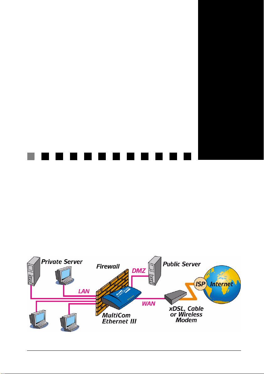
MultiCom Firewalls are available in different hardware configurations to best
meet your needs. Each firewall uses Lightning-Linux to provide additional
features and options to the hardware. In all cases you can configure your firewall
either by using your Internet browser (for Easy Setup, Easy Firewall or Interface
configuration) or by using the Configurator software found on your MultiCom
Companion CD.
Chapter 2
MultiCom Firewall User’s Manual 27
Page 28
Chapter 2 Introducing The MultiCom Firewalls
Introducing the Ethernet II
Back Panel
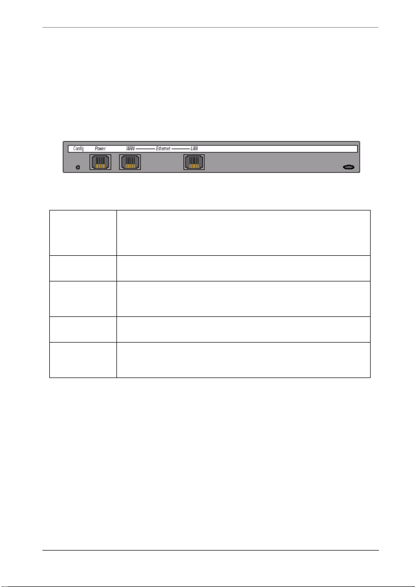
The back panel of your Ethernet II firewall is where all of your cables will
connect to.
Config Push this button and let go when th e fron t LEDs are:
ORANGE to load the last saved boot configuration
GREEN to load the configuration in memory position 1
RED to load the factory default configuration.
Power Use the Power interface to connect to the included MultiCom
power adapter.
LAN Use the LAN (Local Area Network) interface to connect to
your network devices (workstations, printer servers, network
camera) or hub.
WAN Use the WAN (Wide Area Network) interface to connect to
your Broadband modem (xDSL, Cable or Wireless Modem).
Kensington
Lock Slot
This connection is to physically secure your Ethernet firewall
with a Kensington Lock. It is the oblong whole on the right
of the back panel.
28 MultiCom Firewall User’s Manual
Page 29
Front Panel of the Ethernet II
Front Panel of the Ethernet II
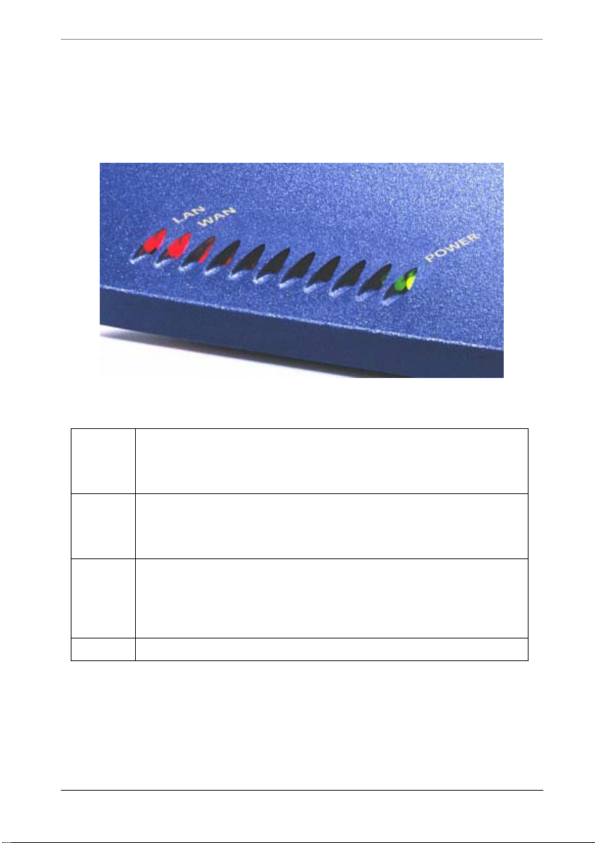
The Front panel of your Ethernet II firewall is where LED lights will inform you
of the activity occurring in your firewall.
LAN Steady GREEN when link is up
Blinking ORANGE when traffic is passing
Blinking RED when packet collisions occur
Steady RED when link is down
WAN Steady GREEN when link is up
First
LED
left of
Power
LED
Power Steady GREEN when power is on
Blinking ORANGE when traffic is passing
Blinking RED when packet collisions occur
Steady RED when link is down
GREEN when SecureWall is ON
ORANGE when filtering is ON and SecureWall is OFF
RED when SecureWall and Filtering are OFF
MultiCom Firewall User’s Manual 29
Page 30
Chapter 2 Introducing The MultiCom Firewalls
Introducing the Ethernet III
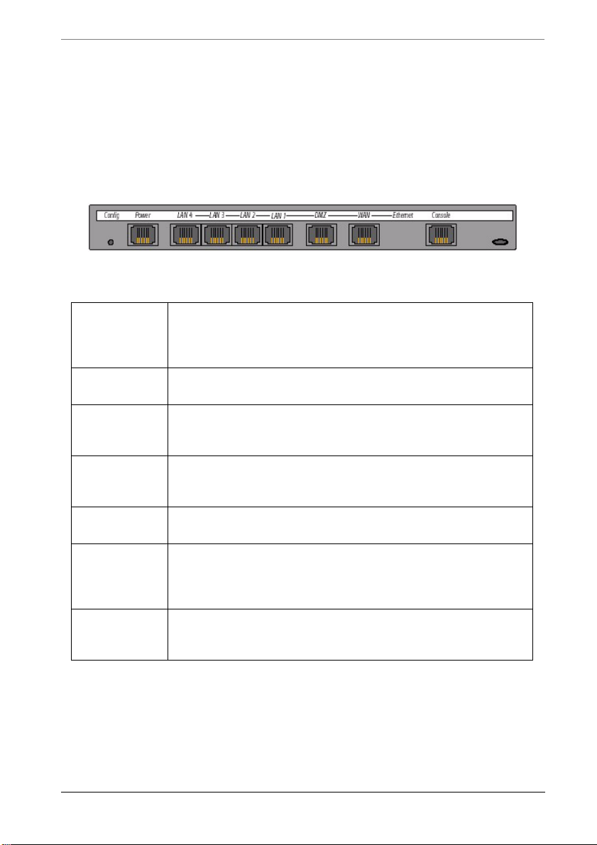
Back Panel
The back panel of your Ethernet III firewall is where all of your cables will
connect to.
Config Push this button and let go when th e fron t LEDs are:
ORANGE to load the last saved boot configuration
GREEN to load the configuration in memory position 1
RED to load the factory default configuration.
Power Use the Power interface to connect to the included MultiCom
LAN 1-4 Use the 4 LAN (Local Area Network) interfaces to connect
DMZ Use the DMZ (Demilitarized Zone) interface to connect
WAN Use the WAN (Wide Area Network) interface to connect to
Console Use the console port with the included cable to connect to the
Kensington
Lock Slot
power adapter.
to your network devices (workstations, printer servers,
network camera).
public servers (www, ftp...). This port allows customized
security for these servers.
your Broadband modem (xDSL, Cable or Wireless Modem).
serial port of your workstation. This allows you direct access
to the CLI (Command Line Interface) an can be used to
configure the firewall.
This connection is to physically secure your Ethernet firewall
with a Kensington Lock. It is the oblong whole on the right
of the back panel.
30 MultiCom Firewall User’s Manual
Page 31

Front Panel of the Ethernet III
Front Panel of the Ethernet III
The Front panel of your Ethernet III firewall is where LED lights will inform you
of the activity occurring in your firewall.
WAN Steady GREEN when link is up
Blinking ORANGE when traffic is passing
Blinking RED when packet collisions occur
Steady RED when link is down
DMZ Steady GREEN when link is up
LAN 1-4 Steady GREEN when link is up
Security GREEN when SecureWall is ON
Power Steady GREEN when power is on
Blinking ORANGE when traffic is passing
Blinking RED when packet collisions occur
Steady RED when link is down
Blinking ORANGE when traffic is passing
Blinking RED when packet collisions occur
Steady RED when link is down
ORANGE when filtering is ON and SecureWall is OFF
RED when SecureWall and Filtering are OFF
MultiCom Firewall User’s Manual 31
Page 32
Chapter 2 Introducing The MultiCom Firewalls
Introducing the MultiCom SpeedSurf
Back Panel
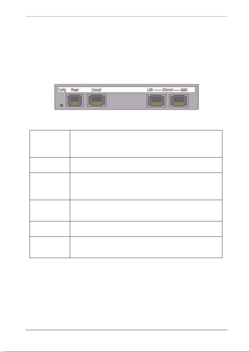
The back panel of your MultiCom SpeedSurf is where all of your cables will
connect to.
Config Push this button and let go when th e fron t LEDs are:
Power Use the Power interface to connect to the included MultiCom
Console Use the console port with the included cable to connect to the
LAN Use the LAN (Local Area Network) interface to connect to
WAN Use the WAN (Wide Area Network) interface to connect to
Kensington
Lock Slot
ORANGE to load the last saved boot configuration
GREEN to load the configuration in memory position 1
RED to load the factory default configuration.
power adapter.
serial port of your workstation. This allows you direct access
to the CLI (Command Line Interface) an can be used to
configure the firewall.
your network devices (workstations, printer servers, network
camera) or hub.
your Broadband modem (xDSL, Cable or Wireless Modem).
This connection is to physically secure your Ethernet firewall
with a Kensington Lock. It is the oblong hole on the right of
the back panel.
32 MultiCom Firewall User’s Manual
Page 33
Front Panel of the MultiCom SpeedSurf
Front Panel of the MultiCom SpeedSurf
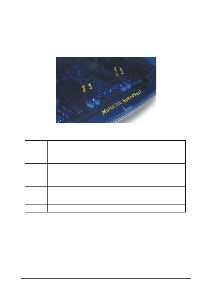
The Front panel of your MultiCom SpeedSurf is where LED lights will inform
you of the activity occurring in your firewall.
LAN Steady GREEN when link is up
Blinking ORANGE when traffic is passing
Blinking RED when packet collisions occur
Steady RED when link is down
WAN Steady GREEN when link is up
Security GREEN when SecureWall is ON
Power Steady GREEN when power is on
Blinking ORANGE when traffic is passing
Blinking RED when packet collisions occur
Steady RED when link is down
ORANGE when filtering is ON and SecureWall is OFF
RED when SecureWall and Filtering are OFF
MultiCom Firewall User’s Manual 33
Page 34
Chapter 2 Introducing The MultiCom Firewalls
Introducing the Enterprise Ethernet
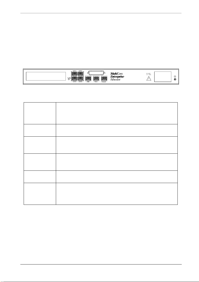
Back Panel
The back panel of your Enterprise Ethernet firewall is where all of your cables
will connect to.
Config Push this button and let go when th e fron t LEDs are:
Power Use the Power interface to connect to the included MultiCom
LAN 1-4 Use the 4 LAN (Local Area Network) interfaces to connect
DMZ Use the DMZ (Demilitarized Zone) interface to connect
WAN Use the WAN (Wide Area Network) interface to connect to
Console Use the console port with the included cable to connect to the
ORANGE to load the last saved boot configuration
GREEN to load the configuration in memory position 1
RED to load the factory default configuration.
power adapter.
to your network devices (workstations, printer servers,
network camera).
public servers (www, ftp...). This port allows customized
security for these servers.
your Broadband modem (xDSL, Cable or Wireless Modem).
serial port of your workstation. This allows you direct access
to the CLI (Command Line Interface) and can be used to
configure the firewall.
34 MultiCom Firewall User’s Manual
Page 35
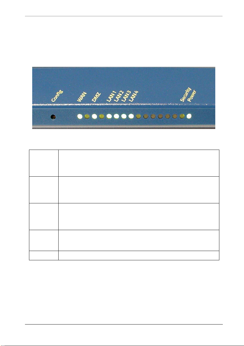
Front Panel of the Enterprise Ethernet
Front Panel of the Enterprise Ethernet
The Front panel of your Enterprise Ethernet firewall is where LED lights will
inform you of the activity occurring in your firewall.
WAN Steady GREEN when link is up
Blinking ORANGE when traffic is passing
Blinking RED when packet collisions occur
Steady RED when link is down
DMZ Steady GREEN when link is up
LAN 1-4 Steady GREEN when link is up
Security GREEN when SecureWall is ON
Power Steady GREEN when power is on
Blinking ORANGE when traffic is passing
Blinking RED when packet collisions occur
Steady RED when link is down
Blinking ORANGE when traffic is passing
Blinking RED when packet collisions occur
Steady RED when link is down
ORANGE when filtering is ON and SecureWall is OFF
RED when SecureWall and Filtering are OFF
MultiCom Firewall User’s Manual 35
Page 36

Chapter 2 Introducing The MultiCom Firewalls
Network Requirements
• Internet Connection (typically a broadband DSL or cable modem) with a
10Mbps (10–base-T) or 10/100Mbps Autosensing Ethernet connection
• One computer with a 10Mbps, 100Mbps, or 10/100Mbps Autosensing
Ethernet interface
• TCP/IP networking protocol for each computer
• (Optionally) a hub or switch to connect more than one computer to your
firewall
• (Optionally) Netscape Navigator 4.0 or higher or Microsoft Internet Explorer
4.0 or higher for interaction with the MultiCom Firewalls administrative web
server.
NOTE — The Internet Connection can also be an office to office
connection such as an ADSL line between two offices and a modem on
each side to provide Ethernet connectivity.
Advanced Configuration Software Requirements
For advanced configuration options you may install or run the Configurator
Software from your MultiCom Companion CD. Below are the requirements to
use this software.
• CD-ROM drive (if installing the Configuration software from CD-R OM)
• Mac OSX, Windows 98, ME, NT4.0, 2000, XP, 2003 or higher, Linux kernel
2.2 or higher, Solaris version 2 or higher
• Pentium CPU, PowerPC CPU or better
• SVGA monitor with at least 800x600 pixel display and 256 colors (more than
256 colors are recommended)
• 64MB of RAM,
• 40 MB of free hard disk space
36 MultiCom Firewall User’s Manual
Page 37

Safety Precautions
Safety Precautions
WARNING THERE ARE NO USER SERVICEABLE PARTS INSIDE THIS
EQUIPMENT. SERVICE MUST BE PERFORMED BY QUALIFIED
SERVICE PERSONNEL. OPENING CASE VOIDS GUARANTEE.
VORSICHT KEIN TEIL IM GEHÄUSE KANN VOM BENÜTZER SELBST
REPARIERT WERDEN. BITTE WENDEN SIE SICH AN QUALIFIZIERTES
WARTUNGSPERSONAL. DAS ÖFFNEN DES GERÄTES FÜHRT ZUM
VERLUST DER GARANTIE.
ATTENTION CET APPAREIL NE CONTIENT AUCUN ELEMENT QUE
L'UTILISATEUR PUISSE REPARER. CONFIEZ LA MAINTENANCE AU
PERSONNEL TECHNIQUE QUALIFIE. L'OUVERTURE DE L'APPAREIL
ANNULE LA GARANTIE.
MultiCom Firewall User’s Manual 37
Page 38

Chapter 2 Introducing The MultiCom Firewalls
38 MultiCom Firewall User’s Manual
Page 39

Getting Started
This chapter will explain the configuration steps necessary to get your MultiCom
Firewall up and running for most local network situations. This includes
configuring to connect to your Internet Service Provider through your existing
xDSL, cable or wireless modem, and configuring your computers to access the
MultiCom Firewall. When you are done you will also have finished setting up the
built-in NAT firewall and all of the computers on your local network will be able
to access the Internet through your firewall.
Be sure that you have asked your ISP how they expect you to connect to the their
services... using DHCP, PPPoE, PPTP, or a static IP Address.
Chapter 3
NOTE — The term “Internet” is used to describe the network that you
use the MultiCom Firewall to connect to. The MultiCom Firewall that
you can also use to connect to other remote computers or servers such
as those at another office site. To keep things simple we will refer to
the external or WAN network as the “Internet”.
Configuring your MultiCom Firewall can be done in 10 steps as shown below.
1. Connect the MultiCom Firewall
2. Configure your computer to communicate with the MultiCom Firewall
MultiCom Firewall User’s Manual 39
Page 40

Chapter 3 Getting Started
3. Activate any option keys
4. Configure the WAN interface to connect to the Internet, your ISP or your
broadband modem
5. Configure the Easy Firewall wizard and optionally redirect specific incoming
traffic to computers on your local network that will act as servers on the
Internet or need special access
6. Save the Configuration
7. Configure the correct date and time
8. Change the default username and password (be sure to pick a names that you
can remember since you cannot retrieve forgotten usernames or passwords)
9. Optionally configure URL Filtering, Stateful Packet Inspection, syslog and
email notifications, dynamic and internal DNS.
10. Register your MultiCom Firewall
Advanced configuration such as Syslog/ SNMP messaging, Dynamic DNS, Local
Name Server, Interface editing (such as MAC address or link speed), NTP, FTP,
customized and standard filters, requires the use of the Configuration Software
and is described in the Lightning-Linux Reference Manual. You will also find
information there on how to install and use the Configurator software.
Connecting the MultiCom Firewall
Following are the steps to connect your MultiCom Firewall to your existing
Ethernet devices. After this physical connection is successful you can begin
configuring the MultiCom Firewall.
1. Connect the WAN interface port to your xDSL, cable, wireless modem or
router with the included cross-wired cable.
2. Connect the LAN interface port to either your computer ethernet interface
(using the blue crossed cable) or to your network hub (using the gray straight
cable).
3. Connect the power cable to the MultiCom Firewall.
4. And finally connect the power transformer to th e w all outlet.
40 MultiCom Firewall User’s Manual
Page 41

Connecting the MultiCom Firewall
WARNING - If you are using an Ethernet III you must reverse the
LAN cable types. In this case the blue crossed cable is only for
connections to a hub and the gray straight cable is only to be connected
to your computer.
After this final step your MultiCom Firewall will power on. The boot process
will cause flashing lights for about 20 seconds. When the Power, LAN and WAN
lights are green then the Firewall is ready for configuration. If either the LAN
or WAN lights remain red then there is a problem with the cable type or the
connected Ethernet device is not turned on. Try using a different cable to
connect to the modem or computer and verify that the other device is turned
on.
The default boot process loads the “boot” configuration and the WAN interface
will begin to search for a DHCP server from your Internet Service Provider.
When the WAN and LAN interfaces turn a steady green to show they are
connected to a network device or blinking yellow to show that data is passing it
will be possible to reach the web server of the firewall. This does not mean that
you are connected to your ISP, only that the cable connection between the
MultiCom Firewall and the modem, router, computer or hub is good. If you have
problems at this point please check the troubleshooting section later in this
manual.
The LAN interface by default has an IP Address of 10.0.0.1, with a subnet
netmask of 255.0.0.0. This will be the IP Address that you use to communicate
and configure your MultiCom Firewall. Other computers using a DHCP client
(the default network configuration for most computers) on your LAN network
will be assigned an IP address between 10.0.0.17 to 10.0.0.254.
Configuration, diagnostics and status information are available from the
MultiCom’s web server at http://10.0.0.1/.
NOTE — The most common setup is when your network modem is
acting as a bridge between you and your Internet Service Provider. It is
possible that your xDSL, cable or wireless modem is acting as a DHCP
server for your network and getting an IP address itself from your
Internet Service Provider.
MultiCom Firewall User’s Manual 41
Page 42

Chapter 3 Getting Started
If this is the case then your MultiCom Firewall will receive its
configuration information directly from your modem. If you are unsure
ask whomever installed your xDSL/ Cable line whether your modem is
acting as a Bridge or as a DHCP Server.
Configuring Your Computers
To communicate with the MultiCom Firewall you will need to be sure that your
computer is configured to access it. There are two general paths for you to follow.
• Set each computer as a DHCP client to receive all necessary information
from the MultiCom Firewall each time you boot up your computer on the
local network.
• Manually choose IP addresses for each computer on your network between
10.0.0.2-10.255.255.255, with a subnet ma sk of 255.0.0.0 and enter in the IP
address of the MultiCom Firewall (10.0.0.1) as the default gateway and DNS
server used to reach the Internet.
The process to enter these settings into your computer varies depending on your
operating system. If you do not see your operating system represented in the
following sections please refer to your computer's user manual for explanations
on configuring your network settings.
Optionally you can make this configuration on only 1 computer to allow access to
the MultiCom Firewall. After you have network access to the MultiCom Firewall
you can reconfigure the LAN IP parameters to another subnet and also deactivate
the DHCP server if there is another being used on you r network.
CAUTION - Windows users who were previously connecting to the
Internet using an analog or built-in modem or special PPPoE software
may need to change their Internet Explorer settings.
Open Internet Explorer, choose Tools and select Internet Options.
Under the Connections tab verify that “Never dial a connection” and
“use local LAN” is selected. Otherwise every time you want to use the
Internet, Windows will try to use the modem.
42 MultiCom Firewall User’s Manual
Page 43
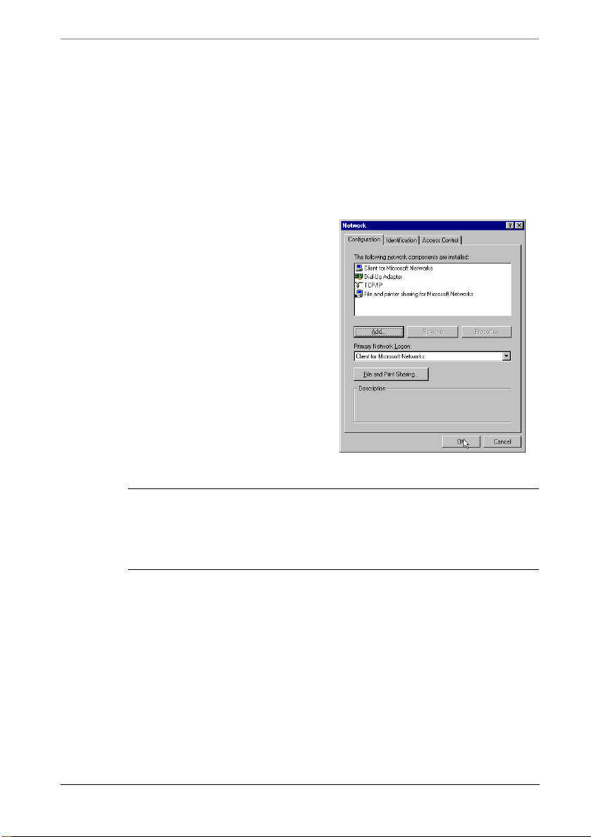
Windows
Windows 9x
To reach the network control on a Windows 95, 98 machine click on
START > Parameters > Control Panel > Network Settings.
In your networking window you
should be in the Configuration
panel. Here you will see the
network devices (such as your
ethernet card/interface) and the
protocols installed for each
device.
Find the setting the says TCP/IP
-> (the name of your
ethernet card)
and double click on it to open
the TCP/IP properties window.
or just TCP/IP
Windows
NOTE — if you have scrolled down to the bottom of the list and do not
see either TCP/IP or the name of your ethernet card/interface then they
are not installed in your computer. Please check the instructions that
came with your ethernet card/interface to install that now.
To set your computer as a DHCP Client
1. choose the IP Address tab
2. click on Obtain IP address automatically.
3. click on OK
4. click on OK
5. follow the onscreen instructions (which will probably have you reboot
your computer)
6. if you have the option to select a DNS server choose Obtain DNS
MultiCom Firewall User’s Manual 43
Page 44
Chapter 3 Getting Started
automatically.
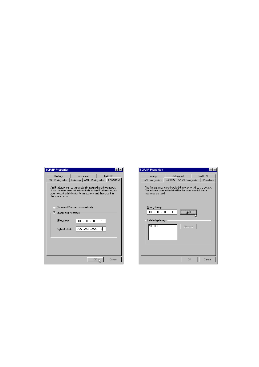
To manually set your computer's IP address
1. choose the IP address tab
2. choose specify an IP address
3. enter the IP address (10.0.0.2 for example) and Netmask for your
computer (the Netmask should be the same as is configured for the LAN
interface of the MultiCom Firewall, by default it is 255.0.0.0)
4. choose the Gateway tab
5. Under New Gateway, enter in the IP address of your MultiCom
Firewall's LAN interface (by default this is 10.0.0.1) and click add
6. click on OK to close and save the properties window
7. click on OK to close and apply the network controls for your computer
8. follow the onscreen instructions (which will probably have you reboot
your computer)
Windows IP Address Panel Windows Gateway Panel
Now you are finished configuring your Windows computer to access your
MultiCom Firewall. Please continue onto the next section to test your that
everything is set up correctly.
Windows 2000 or XP
To reach the network control on a Windows 2000 or XP machine click on
START > Control Panel > Network Connections.
44 MultiCom Firewall User’s Manual
Page 45
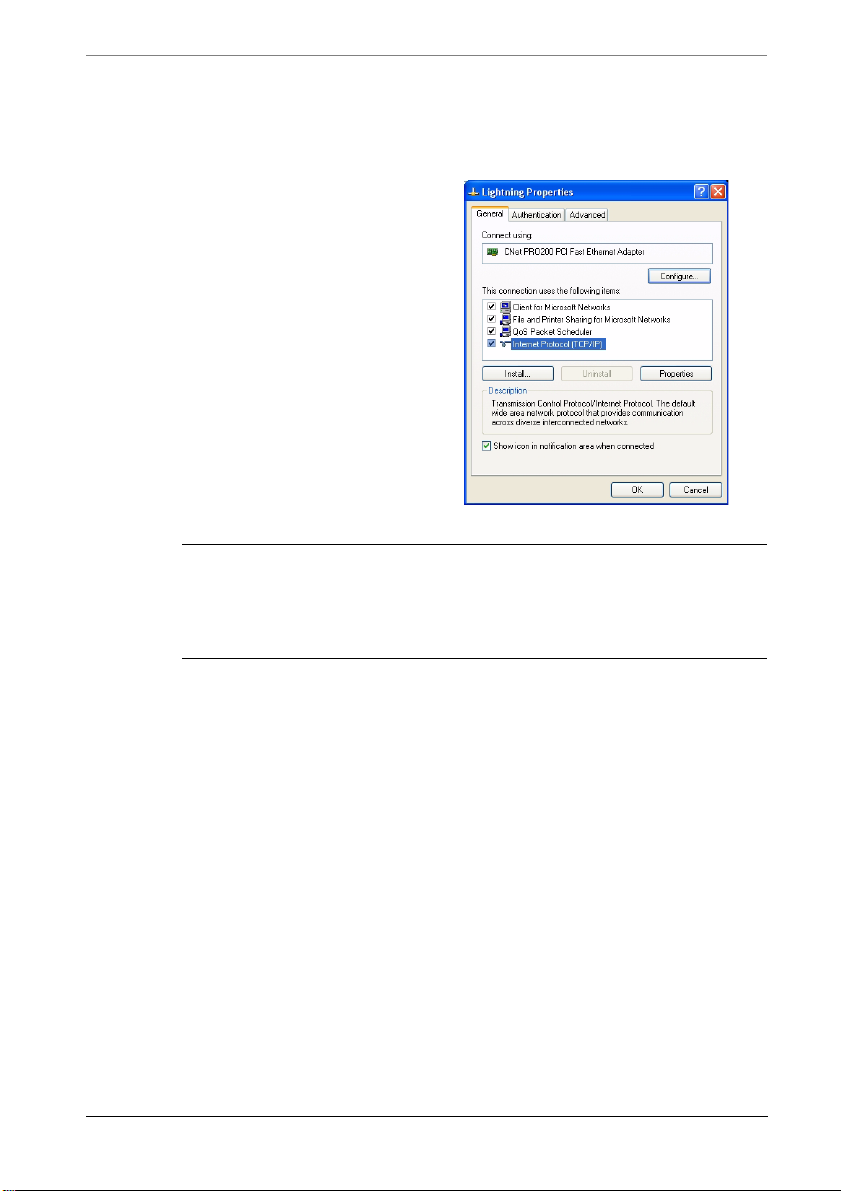
Windows 2000 or XP
Right click on your network
card and select “Properties.”
In your Properties window you
should see the protocols and
services installed for the
selected network device.
Find the setting the says
Internet Protocol (TCP/IP)
and double click on it to open
the TCP/IP properties window.
NOTE — if you have scrolled down to the bottom of the list and do not
see either TCP/IP or the name of your ethernet card/interface then they
are not installed in your computer. Please check the instructions that
came with your ethernet card/interface to install that now.
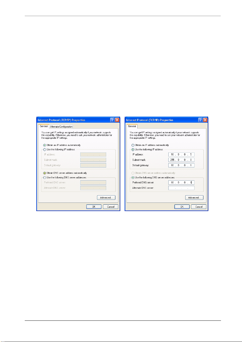
To set your computer as a DHCP Client
1. choose the General tab
2. click on Obtain IP address automatically.
3. click on Obtain DNS server address automatically
4. click on OK
5. follow the onscreen instructions (which might ask you to reboot your
computer)
To manually set your computer's IP address
1.choose the General tab
2.click on Use the following IP address
3.enter the IP address, Subnet mask, and Default gateway. Be sure that the
Subnet Mask and Default gateway match the settings of the MultiCom
Firewall’s LAN interface. For the first connection this should be IP
address 10.0.0.1, Subnet 255.0.0.0, Default gateway 10.0.0.1
MultiCom Firewall User’s Manual 45
Page 46
Chapter 3 Getting Started
4.click on Use the following DNS server addresses
5.Under Preferred DNS server, enter in the IP address of your MultiCom
Firewall's LAN interface (by default 10.0.0.1) or the Primary DNS
server of your ISP
6.Under Alternate DNS server, leave it blank or enter the Secondary
DNS server of your ISP
7.click on OK
8.follow the onscreen instructions (which might ask you to reboot your
computer)
Ethernet DHCP Client Ethernet Static IP Address
Now you are finished configuring your Windows computer to access your
MultiCom Firewall. Please continue onto the next section to verify that
everything is set up correctly.
Macintosh
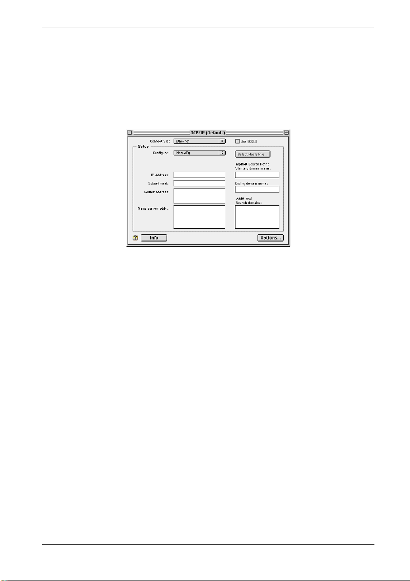
To reach the network control panel on your Macintosh you need to choose on
your
Apple Menu > Control Panels > TCP/IP Panel. This is where you will find
the options to set your Macintosh to use a DHCP server on the network or to use
static IP addressing.
46 MultiCom Firewall User’s Manual
Page 47
Macintosh
These instructions use MacOS9. If you do not see a TCP/IP control panel or are
using an earlier version of the MacOS software please check the documentation
that came with your Macintosh Operating system for instructions on how to load
TCP/IP protocols into your computer.
To set your computer as a DHCP client
1. under Configure select “Using DHCP”
2. close the TCP/IP panel
3. choose “Save” when asked if you want to save your changes
To manually set your computer's IP address
1. under Configure select “Manually”
2. enter the IP address for your computer in the IP address field (10.0.0.2 for
example)
3. enter your network mask in the Network mask field (by default this should be
255.0.0.0)
4. enter your firewall IP address (the IP address of your MultiCom Firewall's
LAN interface, 10.0.0.1 by default) in the
firewall address field
5. enter the DNS server IP addresses in the Name server addr field (by default
this is 10.0.0.1)
6. enter your local domain (if you have one) in the Starting domain name field
7. close the TCP/IP panel
8. choose “Save” when asked if you want to save your changes
MultiCom Firewall User’s Manual 47
Page 48

Chapter 3 Getting Started
Linux
Configuring the network settings for your Linux-based computer will depend on
the type of graphical interface and Linux distribution that you have. Be sure
you've installed the TCP/IP options when you installed your version of Linux.
Otherwise please refer to the documentation that came with your system for the
method of configuring your particular networking options.
The following instructions were used on the Debian distribution by editing the
configuration file at
For configuration of the Ethernet interface to use DHCP services
iface eth0 inet dhcp
To manually set the IP address of the interface card
iface eth0 inet static
address 10.0.0.2
netmask 255.0.0.0
broadcast 10.255.255.255
firewall 10.0.0.1
/etc/network
Choosing the Internet Connection
Common Configurations
There are 5 common ways to configure your new MultiCom Firewall for use on
your network and they are listed below. These assume that your Broadband
modem can be (or already is) configured in “bridging” mode, allowing the
firewall direct access to your ISP network. The option you choose depends on
how your ISP has configured your Internet access. These options are available
using the Easy-Setup on the built-in web server or the Configurator software on
your MultiCom Companion CD.
1. DHCP: requires the ISP to have a DHCP server.
2. PPPoE: requires a PPPoE username, password, and that the broadband
modem is configured into “bridge” mode.
3. PPTP: requires a PPTP username, password and router/server IP addresses of
48 MultiCom Firewall User’s Manual
Page 49

Common Configurations
the Alcatel Modem ANT-1000.
4. Static IP: requires an IP address, subnet mask, default gateway and DNS
parameters.
5. Advanced Configuration where you can fully configure the MultiCom
Firewall to meet your networking needs.
CAUTION - This information must be exactly the same as received
from the ISP or communication to the Internet will not be possible.
Please check with your ISP if you have not received the Internet
Connection type or the connection’s required information. The factory
default setting activates DHCP on the WAN interface.
Option 1: Plug and Play with DHCP. This type of Internet connection is
typical for use with Cable Broadband modems. Does your our Internet Service
Provider uses DHCP to assign you your IP configuration parameters and your
computers are configured as DHCP clients? In this case you can simply plug in
the MultiCom Firewall immediately between your network and your xDSL,
cable or wireless modem to use the default configuration. If your broadband
modem is the DHCP server please read below for additional information.
Option 2: PPPoE is used when your Internet Service Provider requires you to
only have a username and password to access the In ternet. This type of Internet
connection is typical for use with DSL Broadband modems. In this cases you
enter the necessary information using the Easy Setup window of the built-in web
server of your firewall. Click save and you can start surfing the Internet.
Option 3: PPTP with an Alcatel Modem ANT-1000. This process also requires
a username and password. Saving a PPTP configuration using Easy-Setup will
change the default IP address of the MultiCom Firewall’s LAN interface. This
change requires you to reboot your computer after using the Easy-Setup wizard.
Option 4: Static IP Configuration. If your ISP gives you a static IP address you
can also enter this into the Easy-Setup of the MultiCom Firewall. You will also
use this option if you are configuring your MultiCom Firewall for use behind a
pre-existing router which will become your default gateway.
MultiCom Firewall User’s Manual 49
Page 50

Chapter 3 Getting Started
Option 5: Advanced Configuration for advanced users. This gives you access
to all of the parameters of your MultiCom Firewall. Setting these options
requires a good understanding of network terminology and the way your own
network is configured. Please refer to the Lightning-Linux Reference Manual for
a description of Advanced Configuration options.
Special Configurations
If your modem cannot be configured into “bridge” mode you will have to let the
Broadband Modem receive the actual IP parameters from the ISP and share it
with the MultiCom Firewall. In this case you have to make a special
configuration to use the MultiCom Firewall.
Only choose one of these configurations if you cannot use the Common
Configurations above.
1. Broadband Modem receives IP from ISP and is a DHCP server.
2. Broadband Modem receives IP from ISP and has a fixed IP on its LAN
interface.
3. Network router is between Modem and Firewall.
4. Network router is between Firewall and Local Network.
CAUTION - Because you will be creating 2 networks, one between the
MultiCom Firewall and the Broadband Modem and one between the
MultiCom Firewall and the local network you must be sure that both
are using different subnets. For example the default LAN interface
uses subnet 10.0.0.0/255.0.0.0 so if this was used in the final
configuration the WAN should have a different subnet.
When connecting the MultiCom Firewall to a network that is not directly on the
Internet the Firewall will rely on the functionality of the devices between it and
the Internet or between it and the Local Network. Some services might be limited
or require additional configuration as described below.
• the Network Address Translation (NAT) of the Broadband Modem may not
be as powerful as the MultiCom Firewall’s NAT
• if the Broadband modem is using NAT then redirection of incoming traffic to
reach internal servers requires NAT rules on BOTH the Broadband Modem
and the MultiCom Firewall (including configuration for remote access of the
50 MultiCom Firewall User’s Manual
Page 51

Special Configurations
Firewall itself)
• if the modem/ router is using IP addresses in the 10.0.0.0/255.0.0.0 subnet
then you will need to change the IP address and DHCP Server of the
Firewall’s LAN interface (because it uses this subnet by default.)
• if there is a router between the Firewall and the Modem then the router must
be configured correctly to reach the Internet through the Modem or some
other route
Option A: Broadband Modem is DHCP Server. The Broadband modem
receives all of the IP configuration directly from the ISP and uses its own
Network Address Translation to share the connection. In this case you can
simply plug in the MultiCom Firewall immediately between your network and
your xDSL, cable or wireless modem to use the default configuration. If the
Modem uses the 10.0.0.0/255.0.0.0 subnet then you will need to change the LAN
interface to a different subnet. For example you could configure the LAN
interface to use 192.168.0.1, subnet 255.255.255.0. If you change the IP address
of the LAN interface be sure to also change the IP addresses of the LAN’s DHCP
server, in this case to 192.168.0.17-192.168.0.117.
Option B: Static IP with Modem and Firewall. If the Broadband Modem does
not offer a DHCP server then you will need to use the Easy Setup’s Static IP
configuration to allow the MultiCom Firewall to reach it. Configure the WAN
interface of the Firewall to be on the same network as the Modem. For instance if
the Modem has an IP address of 192.168.0.1, subnet 255.255.255.0 then
configure the Firewall’s WAN IP address to be 192.168.0.2, subnet
255.255.255.0. The default gateway will be the IP address of the Modem, in this
example it is 192.168.0.1. The DNS parameters should be those of ISP.
Option C: Router between Modem and Firewall. In this case you will need to
use the Easy Setup’s Static IP configuration to allow the MultiCom Firewall to
reach the Router and the router must be configured to reach the Modem and/ or
Internet. Configure the WAN interface of the Firewall to be on the same network
as the router. For instance if the router has an IP address of 192.168.0.1, subnet
255.255.255.0 then configure the Firewall’s WAN IP address to be 192.168.0.2,
subnet 255.255.255.0. The default gateway will be the IP address of the router, in
this example it is 192.168.0.1. The DNS parameters should be those of ISP.
Option D: Router between Firewall and Local Network. In this case configure
the WAN interface using the Easy Setup for Internet Access. Then configure the
router to use the LAN interface of the MultiCom Firewall as the default gateway
MultiCom Firewall User’s Manual 51
Page 52

Chapter 3 Getting Started
for all Internet Traffic. Additionally, the MultiCom needs to know that the actual
Local Network is behind the router. This requires the use of the Configurator
software and is described in the Routing chapter of the Reference Manual.
Configuration Checklist
Before you start the configuration there is some required information needed for
your MultiCom Firewall to work correctly. If any of the following terms are
unfamiliar to you please check with your Internet Service Provider or the glossary
at the end of this book.
Below you can find the default configuration of the LAN side of your MultiCom
Firewall. This is the part of the MultiCom Firewall that is connected directly to
your local/home network. These settings can be changed by you during the Easy
Setup, visiting http://10.0.0.1/setup/lan/ or with the Configurator software.
Table 3: Pre-set configuration of MultiCom Firewall
Configuration Questions Your Choices
IP Address of the LAN interface 10.0.0.1
Subnet Mask of your network 255.0.0.0
Will you use DHCP on your LAN? Yes
IP address range for your internal network 10.0.0.17 - 10.0.2.254
User name to configure the MultiCom Firewall multicom
Password to configure the MultiCom Firewall (there is no password)
IP Configuration of the WAN interface DHCP Client
DNS Proxy and Cache Activated
NAT Firewall Activated
NOTE — When using the DHCP server of your firewall the necessary
IP parameters will be distributed to your LAN by the built-in DHCP
server. This saves you from having to manually configure each
computer. There can only be one DHCP server on any network.
If your ISP or your Broadband Modem uses DHCP please skip ahead to the next
section because you can use the Plug & Play Configuration.
52 MultiCom Firewall User’s Manual
Page 53

Interface Configuration Options
Table 4: Interface Configuration Options
WAN LAN DMZ (Ethernet III only)
DHCP client DEFAULT optional optional
DHCP server optional DEFAULT optional
PPPoE optional optional optional
PPTP optional optional optional
Static/ Manual optional optional optional
If your Internet Service Provider does not provide DHCP configuration the
following information will be necessary for you to communicate through your
MultiCom Firewall. For PPTP connections this extra information is necessary
because you are forming two TCP/IP network links: between your Broadband
Modem <--> MultiCom Firewall and between the MultiCom Firewall <--> your
network.
If your ISP is using PPPoE or PPTP fill in either the PPPoE/PPTP configuration
checklist or the Static configuration checklist depending on how your Internet
Service Provider wants you to connect to the Internet.
Table 5: PPPoE/PPTP configuration checklist for WAN interface
Parameters Information from your Internet
Service Provider
the username assigned to you by your
Internet Service Provider
the password assigned to you by your
Internet Service Provider
the domain name of your Internet
Service Provider or yours (optional)
PPTP Only: what is the IP Address of
your modem (default 10.0.0.138)
PPTP Only: what is the subnet mask
of your modem (default 255.0.0.0)
If you are not using DHCP, PPPoE, or PPTP then you will need to configure a
Static IP configuration. The table below is all of the information that you will
need from your ISP to successfully make a connection to the Internet.
MultiCom Firewall User’s Manual 53
Page 54
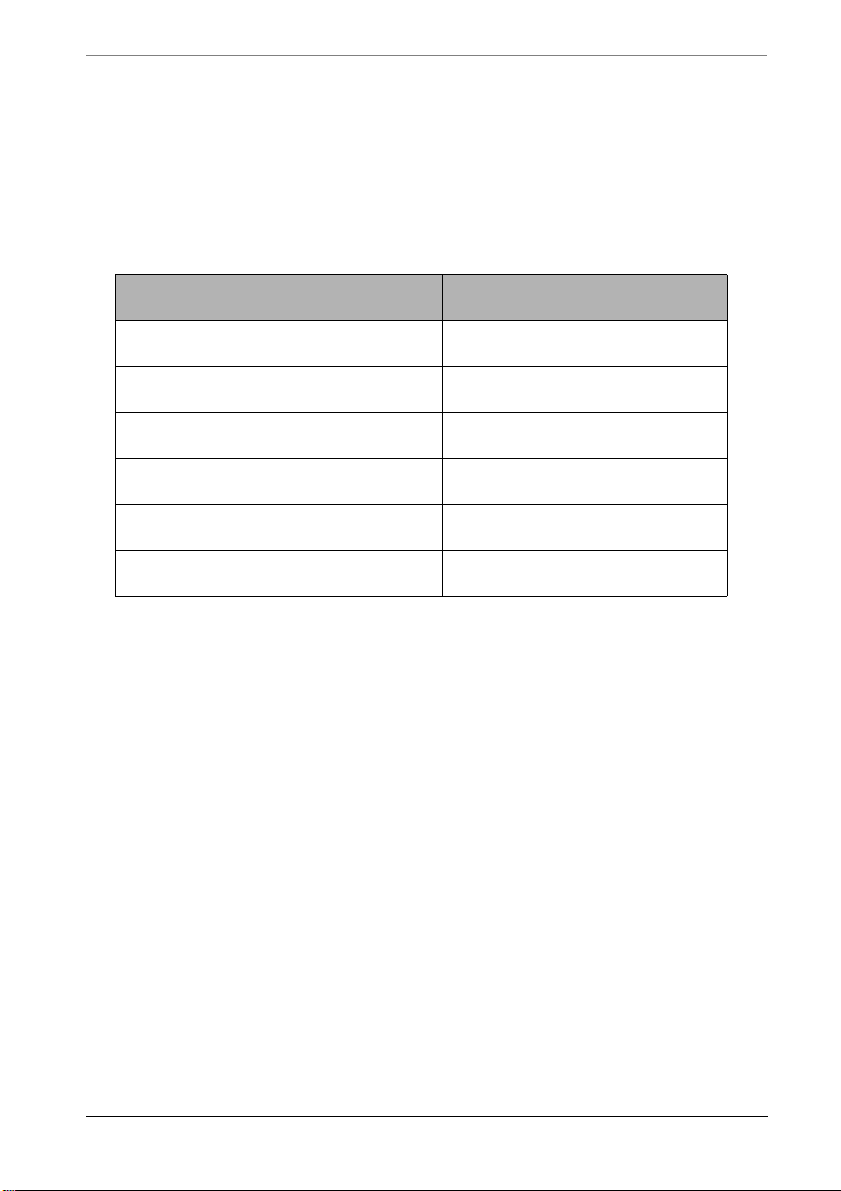
Chapter 3 Getting Started
If you have a pre-existing router between the broadband access modem and the
MultiCom Firewall you will also need to use the Static IP Configuration option of
the Easy-Setup. The Firewall WAN IP address parameters must match the subnet
of your router and the router IP address should be the default gateway. Be sure to
enter in your ISP’s DNS information as well.
Table 6: Static configuration checklist for WAN interface
Parameters Information from your Internet
Service Provider
the IP address assigned to you by
your Internet Service Provider
the IP netmask used by your Internet
Service Provider
the default gateway of your Internet
Service Provider
the domain name of your Internet
Service Provider or yours
the primary IP address of the DNS of
your Internet Service Provider
the secondary DNS IP Address of
your Internet Service Provider
If you do not know this information check with your Internet Service Provider
support services or the documentation you received from them when you joined
them.
Plug & Play Configuration: DHCP
Here are the requirements necessary to install the MultiCom Firewall without
configuration.
1. Is your Internet Service Provider giving you your IP address, DNS server
address and default firewall configuration with a DHCP server?
2. Are all of your internal network (LAN) devices configured as DHCP Clients?
If your Internet Service Provider uses DHCP to assign you your IP configuration
parameters and your computers are configured as DHCP clients you can simply
plug in the MultiCom Firewall immediately between your network and your
xDSL, cable or wireless modem. In this case it will automatically be a firewall
protecting your internal network (LAN) and enable all of your LAN computers to
use the same Internet account.
54 MultiCom Firewall User’s Manual
Page 55

Using the Easy Setup
TIP - Instructions on configuring your computers to use DHCP is in
the “Configuring Your Computers” Section on page 42.
If you answered yes to the two above questions then you only need to plug in your
cables to the MultiCom Firewall. If a DHCP server is found on the WAN, your
MultiCom Firewall will be assigned an IP address by your Internet Service
Provider (or possibly your modem, see NOTE below). Additionally, all needed
information to communicate with the Internet Service Provider through the
modem will be passed to the MultiCom Firewall, which in turn passes it to the
DHCP client computers on your network so that they can access the Internet.
If no DHCP server is found the MultiCom Firewall will not be able to connect to
the Internet until a different configuration is loaded. If no DHCP service is
provided you will need to run the Easy-Setup from the built-in web server of the
MultiCom Firewall or use the Configurator software from the Companion CD to
properly configure your MultiCom Firewall.
CAUTION - Some Internet Service Providers that use DHCP also
require you to register the hardware MAC address of your computer’s
Ethernet card. If this was the case you will either have to ask them to
change the MAC address to the WAN interface of your MultiCom
Firewall (00:90:f4:xx:xx:xx where xx:xx:xx is the 6 digit/ letter serial
number of your Firewall) or use the Configurator software to change
the MAC address of your MultiCom Firewall. Please see the
Reference Manual for more information on this process.
Diagnostics and status information on this connection is available from the
MultiCom web server at http://10.0.0.1/status/wan/ and from the DHCP tab of
the Configurator software’s Monitor window. DHCP activity can also be logged
by activating Syslog using the Advanced Config option.
Using the Easy Setup
The built-in Easy Setup of your MultiCom Firewall’s web interface has been
designed to get your Internet connection started as quickly as possible. You will
need an Internet web browser installed to use this option. If you do not have one
MultiCom Firewall User’s Manual 55
Page 56
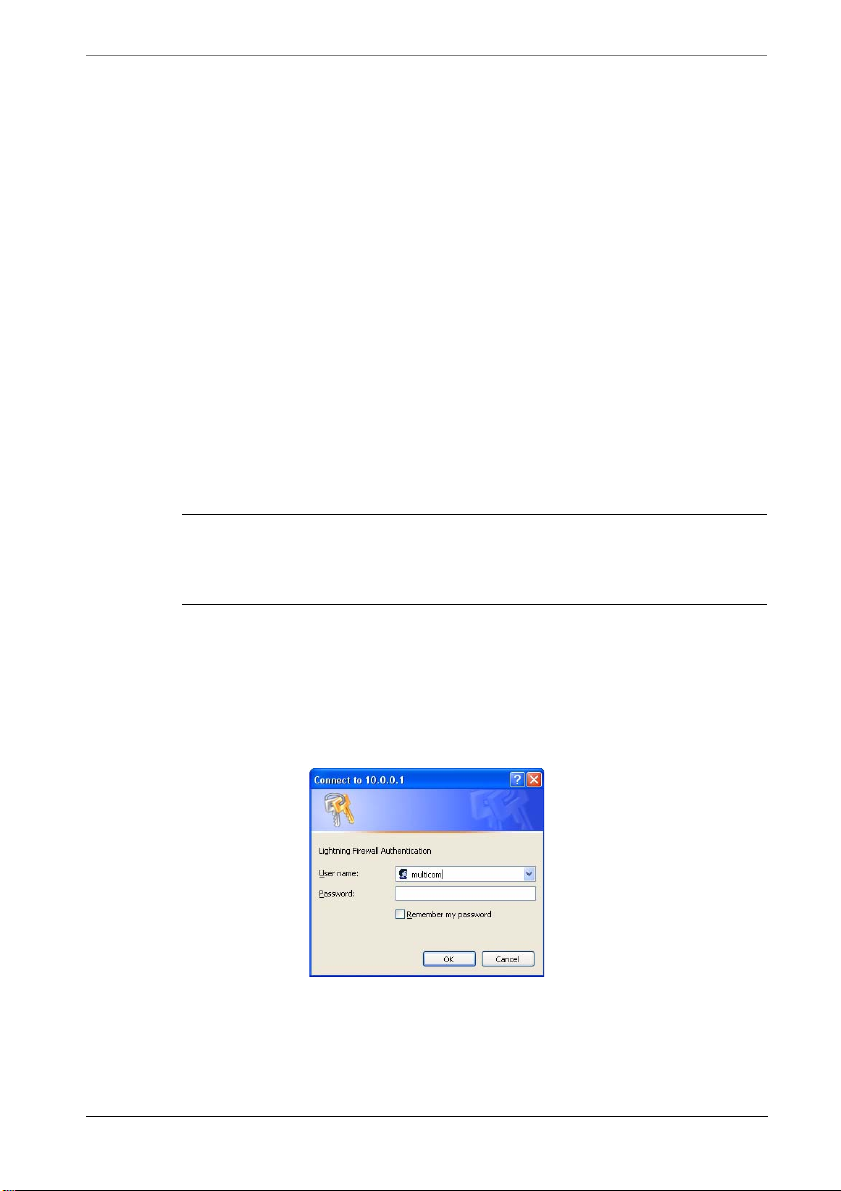
Chapter 3 Getting Started
you can install a web browser from the MultiCom Companion CD that came with
your firewall. Just go to the 3rd Party Software section and install Netscape,
Internet Explorer, Mozilla or Firefox.
To properly configure your firewall we will be using the information that you
have written in the Pre-Configuration Checklist. Please be sure that you have
filled in that information now before continuing.
Accessing the Easy Setup Web Server
For the following explanation we assume that you will be directly connected to
your firewall. Your computer must be configured as a DHCP client to configure
the MultiCom Firewall (optionally a computer with a static IP address between
10.0.0.2-10.255.255.255 and with a subnet mask of 255.0.0.0 can be used.) If
you are unsure how to do this see the previous section on Configuring Your
Computers.
CAUTION - if your MultiCom Firewall does not respond you may
need to reset it to its default settings. Refer to the Resetting Default
Settings section of the Troubleshooting chapter.
Open up a web browser and enter in the IP address of your MultiCom Firewall
(the factory default is http://10.0.0.1) You will be asked for the username and
password allowed to access the firewall. The default settings for the MultiCom
Firewalls is username=” multicom” and no password. Enter this information now
and click OK.
The next screen that you will see is the MultiCom Web Server window. Here you
select the Easy Setup option.
56 MultiCom Firewall User’s Manual
Page 57
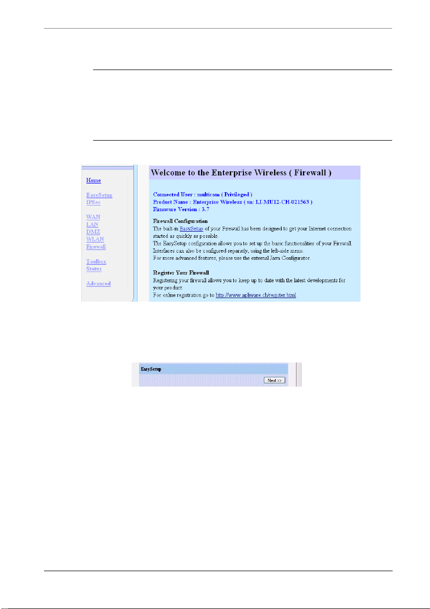
WAN DHCP Easy Setup
CAUTION — Remember that you must be using a computer that
either is set as a DHCP Client or has a static IP Address (in the 10.x.x.x
range, for example 10.0.0.2) and a subnet mask of 255.0.0.0.
Otherwise you will not be able to communicate with the MultiCom
Firewall in its default settings.
The Easy Setup window (below) allows for fast configuration of your MultiCom
Firewall. After reading the warning click the “Next” button to start configuring
the WAN interface.
The next choice depends on how your Internet Service Provider connects you to
the Internet. You will see the WAN Configuration webpage where you can select
the Connection Type that your ISP has asked you to use. The next four sections
describe the 4 possibilities for configuring the WAN interface using DHCP,
PPPoE, PPTP or a static configuration.
WAN DHCP Easy Setup
If your Internet Service Provider connects you using a DHCP server you will not
have to configure any parameters with Easy Setup because this is the default
mode of the MultiCom Firewall. During the bootup of your firewall in its default
mode it will automatically search for the DHCP server and configure itself with
everything needed to reach the Internet Service Provider.
MultiCom Firewall User’s Manual 57
Page 58
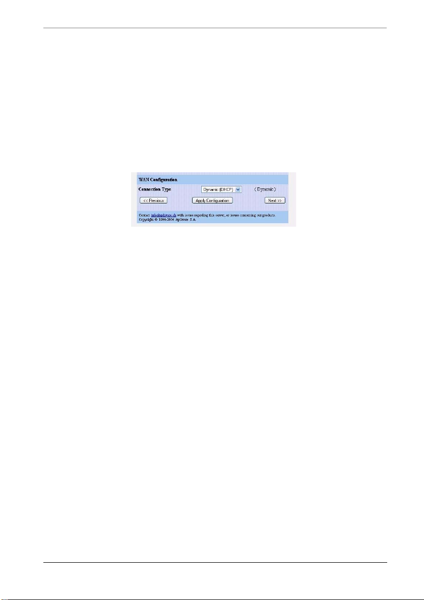
Chapter 3 Getting Started
If you use the Easy Setup window to configure DHCP you will have the option to
configure the DHCP settings on your LAN interface. This allows you to
customize the IP addresses assigned by your firewall or to disable this
functionality. Please refer to the Lightning-Linux Reference Manual chapter on
DHCP for more information on using this option.
1. Select Dynamic (DHCP) in the Connection Type box to see the Easy Setup
configuration options.
2. Optionally give a name to your MultiCom Firewall.
3. Click the Next button and goto the Section “LAN Easy Setup” on page 63.
WAN PPPoE Easy Setup
If your Internet Service Provider connects you using a PPPoE server you need to
click the PPPoE option in the Easy Setup window (see the window above). This
window only requires a username and password to access your Internet Service
Provider. This information is available from your Internet Service Provider.
The PPPoE setting causes the MultiCom Firewall to automatically and regularly
demand its IP configuration from a PPPoE server connected through the WAN
interface using the username and password. All needed Internet parameters such
as the MultiCom Firewall’s IP address, IP subnet, default gateway, and external
DNS servers will be automatically requested directly from the ISP using the
PPPoE protocol. Below are the steps necessary to configure a PPPoE
connection.
1. Select PPPoE in the Connection Type box and click the “Next” button to see
the following Easy Setup configuration option page.
58 MultiCom Firewall User’s Manual
Page 59
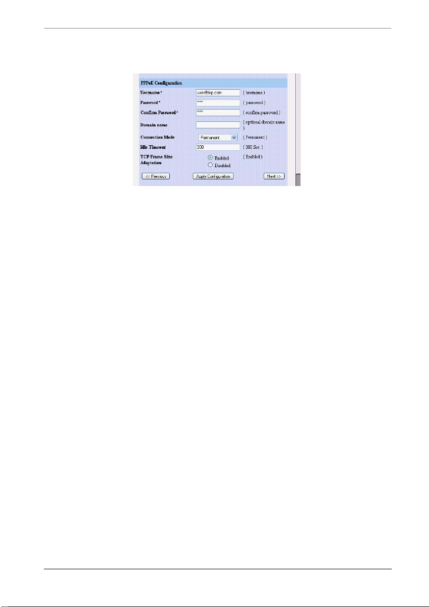
WAN PPTP Easy Setup
2. Enter in the username that your Internet Service Provider gave to you.
3. Enter in the password that your Internet Service Provider gave to you.
4. Optionally enter in your local domain name. (This will become the default
suffix used for networking activity.)
5. Select the PPP connection mode that you wish to use: Permanent is an always
on connection, Dial on Demand only connects to the Internet when there is
network traffic, and Manual requires manually opening or closing the
Internet connection from the web interface.
6. Select the PPP connection idle time out if you are using Dial on Demand.
When there is no network activity this is the number of seconds before the
PPP connection is closed.
7. Optionally enable the TCP Frame Size Adaption as a troubleshooting step if
you are having problems connecting to your Internet Service Provider or
certain web pages.
8. Click the Next button and goto the Section “LAN Easy Setup” on page 63.
Diagnostics and status information on this connection is available from the
MultiCom web server at http://10.0.0.1/status/wan/ or from the PPP tab of the
Configurator software’s Monitor window. PPPoE activity can also be logged by
activating Syslog using the Advanced Config option. See the User’s Manual for
more instructions.
WAN PPTP Easy Setup
If your Internet Service Provider connects you using a PPTP server you need to
click the PPTP option in the Easy Setup window (see the main window above).
This window requires a username and password to access your Internet Service
MultiCom Firewall User’s Manual 59
Page 60

Chapter 3 Getting Started
Provider. Additionally you will need to enter the IP Address and Subnet Mask of
your broadband modem. This information is available from your Internet Service
Provider.
The PPTP setting causes the MultiCom Firewall to automatical ly and regularly
demand its IP configuration from a PPTP server connected through the WAN
interface using a username and password. All needed Internet parameters such as
the MultiCom Firewall’s IP address, IP subnet, default gateway, and external
DNS servers will be automatically requested directly from the ISP using the
PPTP protocol.
It is important to know the existing IP configuration of the modem offering a
PPTP server because the MultiCom Firewall WAN interface mst be on the same
subnetwork as the Ethernet interface of the modem. This creates 2 networks, one
between the MultiCom Firewall and the broadband modem and one between the
MultiCom Firewall and the local network. By default this PPTP Setup Panel
configures your WAN interface’s network to be 10.0.0.1/255.0.0.0, expects to
find the broadband modem at IP address 10.0.0.138, and changes the LAN
interface to 192.168.1.1/255.255.255.0. Although this is a very common
configuration it may not be the way your broadband modem is configured. Be
sure to verify
CAUTION - Saving a PPTP configuration using Easy-Setup will
change the default IP address of the MultiCom Firewall’s LAN
interface. This change requires you to reboot your computer after
using the Easy-Setup wizard
1. Select PPPoE in the Connection Type box and click the “Next” button to see
the following Easy Setup configuration option page. This is where you enter
in your username and password, modem IP Address, WAN IP Address and
Subnet Mask.
60 MultiCom Firewall User’s Manual
Page 61
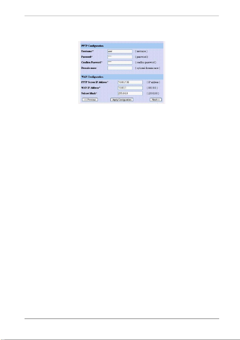
WAN Static IP Easy Setup
2. Enter in the username that your Internet Service Provider gave to you.
3. Enter in the password that your Internet Service Provider gave to you.
4. Optionally enter in your local domain name. (This will become the default
suffix used for networking activity.)
5. Enter in the IP Address of the broadband modem that is your PPTP Server.
6. Enter in the IP Address for the WAN interface for the MultiCom Firewall.
This address must be on the same subnet as the IP Address of the broadband
modem. For instance if your modem 10.0.0.138 then your WAN interface
would probably have and IP Address of 10.0.0.1 .
7. Enter in the Subnet Mask of the broadband modem.
8. Click the Next button and goto the Section “LAN Easy Setup” on page 63.
WAN Static IP Easy Setup
In some cases your Internet Service Provider will have you configure all of the
necessary information manually. This is common when you are assigned a static
IP address that will not change. The needed configuration information is
available from your Internet Service Provider. Below are the steps necessary to
configure a Static connection.
In a Static IP connection all Internet parameters such as the MultiCom Firewall’s
IP address, IP subnet, default gateway, and external DNS servers must be
manually configured. If your ISP has told you to manually configure your WAN
interface this is where you will enter in the information that they send you.
MultiCom Firewall User’s Manual 61
Page 62
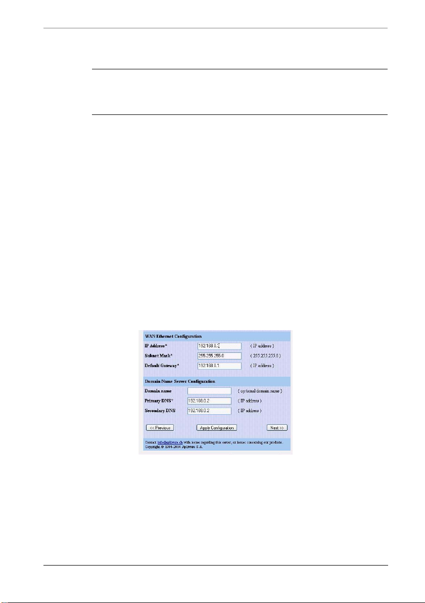
Chapter 3 Getting Started
TIP - If you have a pre-existing router in front of your MultiCom
Firewall you will use its IP Address as the default gateway and need to
be sure that your WAN interface is on the same subnet as the router.
1. Select Static in the Connection Type box and click the “Next” button to see
the following Easy Setup configuration option page. This is where you
manually enter in all of your WAN interface IP parameters. Your ISP should
have provided you with all of the information necessary to fill in this form.
2. Enter in the WAN IP Address that your MultiCom Firewall will be known as
(provided by your Internet Service Provider.)
3. Enter in the WAN Subnet Mask that will be used between the Internet
Service Provider and the MultiCom Firewall.
4. Enter in the Default Gateway address (otherwise known as the IP address of
the Internet Service Provider's firewall).
5. Optionally enter in your local domain name. (This will become the default
suffix used for networking activity.)
6. Enter in the IP addresses of your Internet Service Provider's Primary and
Secondary DNS servers.
7. Click the Next button and goto the Section “LAN Easy Setup” on page 63.
62 MultiCom Firewall User’s Manual
Page 63
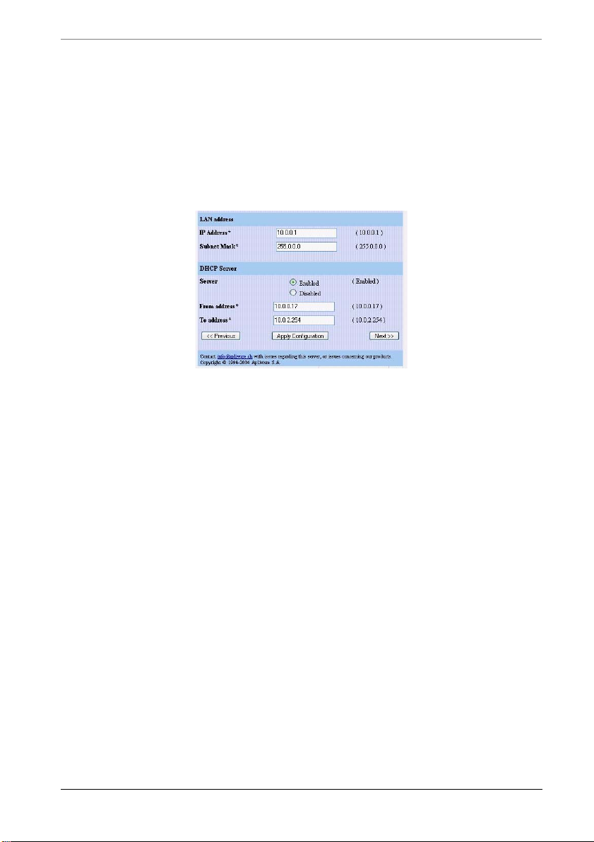
LAN Easy Setup
LAN Easy Setup
After finishing the WAN configuration as instructed by your ISP you can
optionally change the default LAN configuration settings for your local network.
You should not normally change these settings unless you know what you are
doing and can just click the Next button to continue. For more information about
DHCP options refer to the DHCP Chapter of the Reference Manual.
1. Enter in the LAN IP Address that your MultiCom Firewall will be known as
(provided by your Internet Service Provider.) This cannot be on the same
subnet as the WAN interface.
2. Enter in the LAN Subnet Mask that will be used on your local network.
3. Choose to enable or disable the built-in DHCP server for managing your
network. By default this is enabled and should not be changed unless you
have another DHCP server on your network.
4. If you enabled the DHCP server, choose the first IP address that the
MultiCom Firewall should assign on your local network to DHCP clients.
This IP Address must be on the same subnet as the LAN IP Address.
5. If you enabled the DHCP server, choose the last IP address that the
MultiCom Firewall should assign on your local network to DHCP clients.
This IP Address must be on the same subnet as the LAN IP Address. All
addresses between the “From address” and the “To address” can be assigned
by the MultiCom Firewall to computers on your local network.
6. Click the Next button and goto the next Section.
MultiCom Firewall User’s Manual 63
Page 64
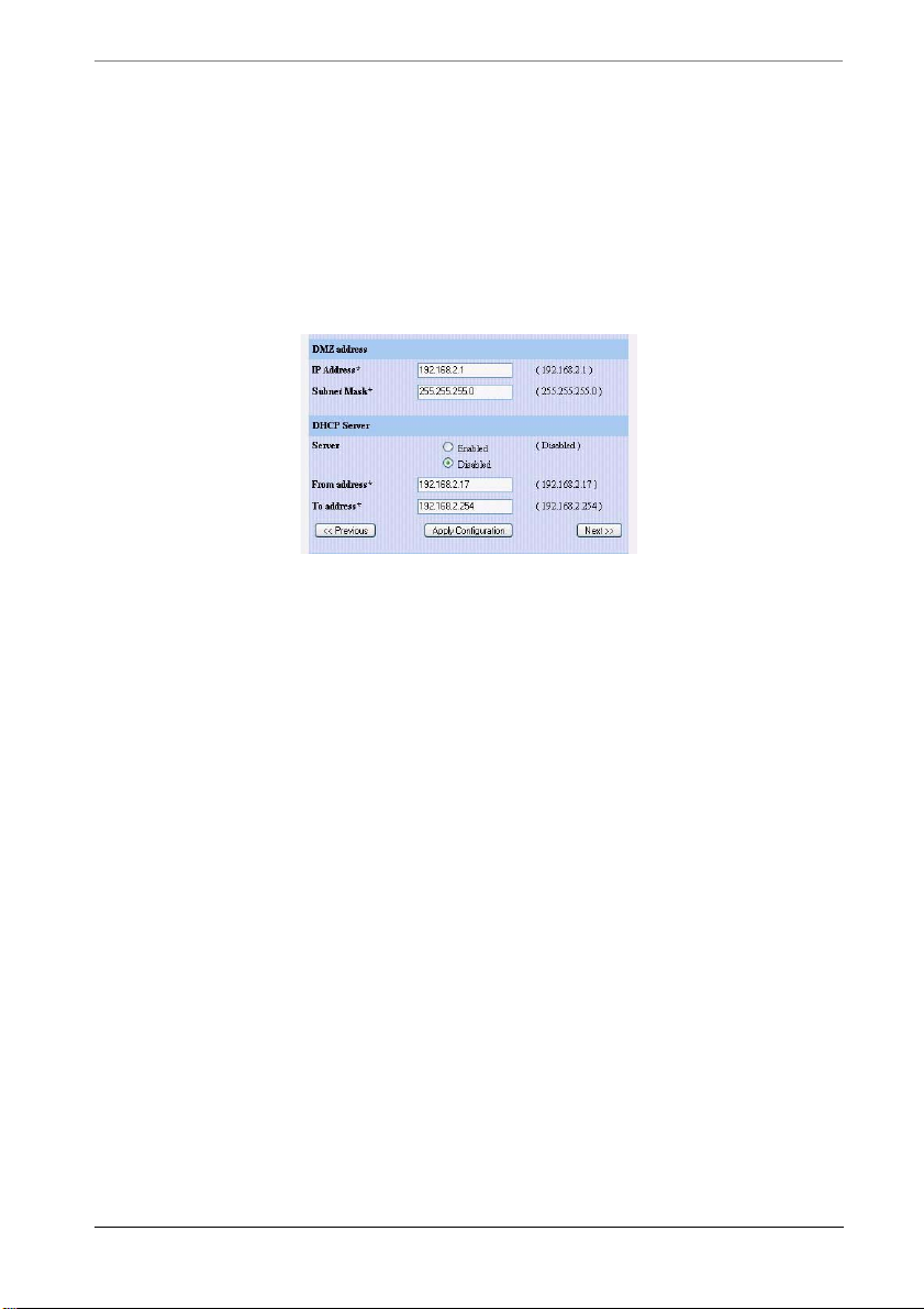
Chapter 3 Getting Started
DMZ Easy Setup
If your MultiCom Firewall has a DMZ interface this webpage will appear next. If
you do not have a DMZ interface you will immediately go to the Firewall Easy
Setup configuration webpage. If you want to leave the DMZ disabled just enter
0.0.0.0 for the IP address and 0.0.0.0 for the subnet mask. You can activate it
later.
1. Enter in the DMZ IP Address that your MultiCom Firewall will be known as
(provided by your Internet Service Provider.) This cannot be on the same
subnet as the WAN or LAN interfaces.
2. Enter in the DMZ Subnet Mask that will be used on your local network.
3. Choose to enable or disable the built-in DHCP server for managing your
network. By default this is enabled and should not be changed unless you
have another DHCP server on your network.
4. If you enabled the DHCP server, choose the first IP address that the
MultiCom Firewall should assign on your DMZ network to DHCP clien ts.
This IP Address must be on the same subnet as the DMZ IP Address.
5. If you enabled the DHCP server, choose the last IP address that the
MultiCom Firewall should assign on your DMZ network to DHCP clien ts.
This IP Address must be on the same subnet as the DMZ IP Address. All
addresses between the “From address” and the “To address” can be assigned
by the MultiCom Firewall to computers on your DMZ network.
6. Click the Next button and goto the next Section.
64 MultiCom Firewall User’s Manual
Page 65
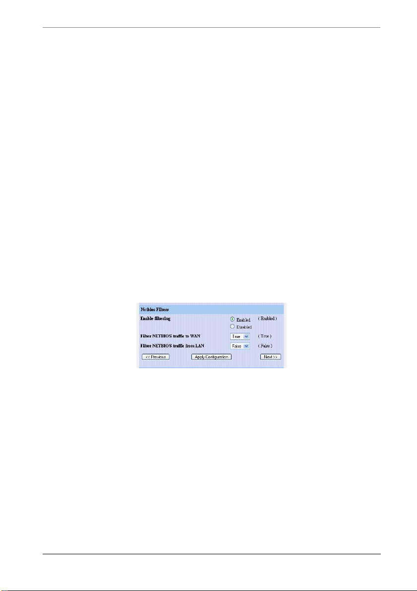
Easy Firewall Setup
Easy Firewall Setup
Although the SecureWall blocks all incoming traffic arriving at the WAN
interface except the traffic which is a response to a data request from the LAN or
DMZ networks you may wish to allow customized remote access to your
MultiCom Firewall or your local network.
The Easy Firewall Setup is part of the Easy Setup wizard of the Web Interface but
it can also be used separately on the MultiCom Firewall by using a web browser
to go to http://10.0.0.1/setup/fw/ (where 10.0.0.1 is the IP address of the LAN
interface of the Firewall.). Additional options are provided by the next 2
webpages.
Firewall Filters
The first part of the Firewall Easy Setup webpages allows you to enable or
disable the Stateful Packet Inspection Firewall to work along with the
SecureWall firewall. When filtering is enabled all traffic from the DMZ
network (if available) to the LAN is blocked. Additionally you can choose
to block NetBIOS traffic directed to the WAN interface or coming from
the LAN interface.
Additional rules can be customized using the Configurator software and is
described in the Lightning-Linux Reference Manual chapter on Filtering. When
you are finished click the “Next” button.
Host Mapping
If you make servers on your local network available to users on the
Internet (for instance a web or email server) you may enter the IP address
on your local network of those servers. Rules will be made to allow access
to these servers in the SecureWall and Stateful Filtering Firewall. External
users will use the IP address of the WAN interface and be redirected to
these internal servers.
MultiCom Firewall User’s Manual 65
Page 66
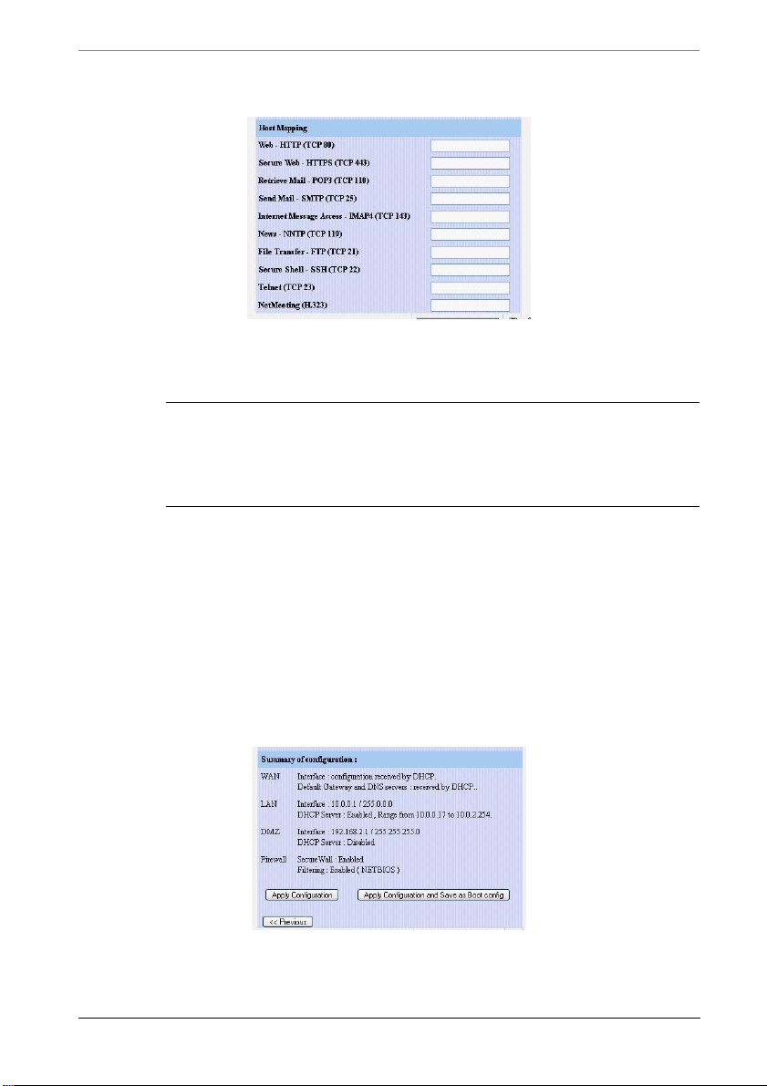
Chapter 3 Getting Started
To activate services not in the list, use the Easy Firewall of the Configurator
software. When you are finished click the “Next” button.
NOTE - to make secure remote access to your MultiCom Firewall for
configuration simply enter in the IP address of the LAN interface (by
default 10.0.0.1) in the “SecureWeb - HTTPS (TCP 443)” and or the
“Secure Shell - SSH (TCP 22)” server fields.
Saving The Configuration
1. Finally you have a summary of your chosen configuration and the choice of
how to save it. You can either choose Apply Configuration to save the
configuration to the temporary memory and start using it right away or you
can choose Apply Configuration and Save as Boot config. The second option
makes your changes permanent, in case you need to reboot your firewall or
there is a power outage. The second option is the recommended option.
66 MultiCom Firewall User’s Manual
Page 67
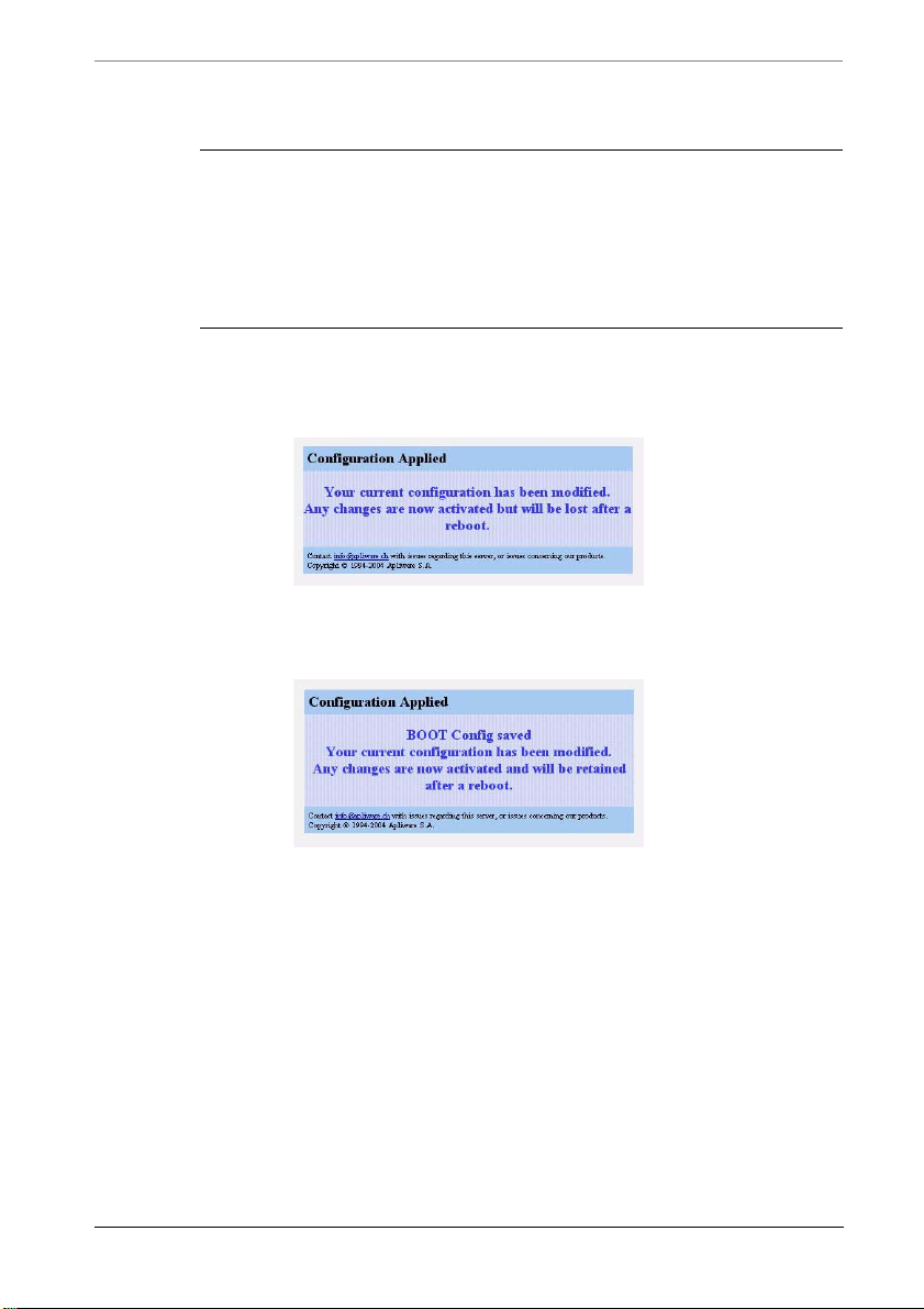
Fine Tuning Your Configuration
NOTE — Choosing Apply Configuration and Save as Boot
activates and saves the configuration changes you have made
config
so that when the MultiCom Firewall is rebooted your changes will still
be there. If you choose
activated but the next time you reboot your MultiCom Firewall these
changes will also be deleted.
2. When the configuration has been successfully saved using the Apply
Configuration button you will see the following screen. Your Easy Setup
configuration is now finished.
3. If you saved your configuration using the Apply Configuration and Save as
Boot config button you will see the following screen. Your Easy Setup
configuration is now finished.
Apply Configuration then the changes will be
Fine Tuning Your Configuration
The default configuration that you have just set up enables the basic features of
your MultiCom Firewall such as Internet Connection Sharing and the SecureWall
to protect your network. For more advanced features please refer to the
Lightning-Linux Reference Manual for your firmware version.
MultiCom Firewall User’s Manual 67
Page 68
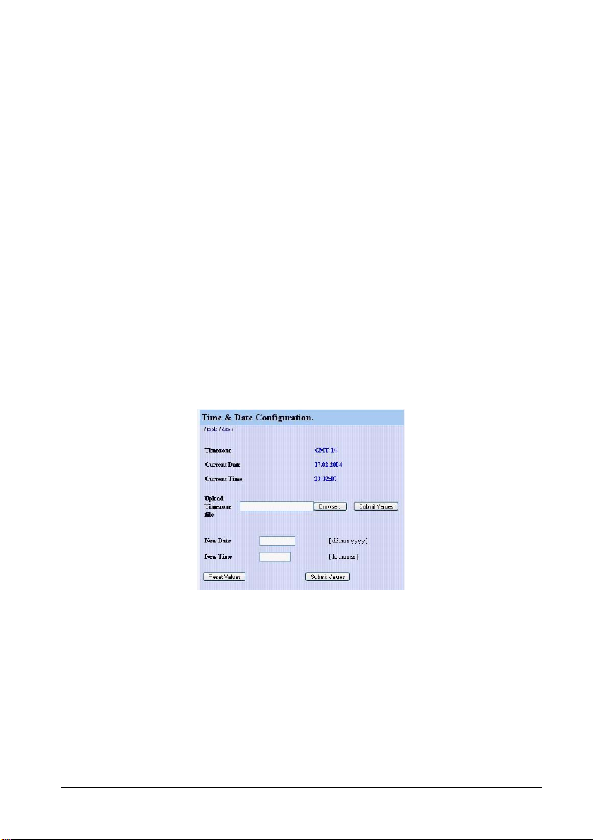
Chapter 3 Getting Started
Activate Option Keys
If you have received an Option Key you will need to enter it into the MultiCom
Firewall for the new features to be activated. The Option key is a text file that is
usually received in an email. You can either save the attached text message to
your computer or you can make a new, empty text file and copy and paste the
contents of the key into it.
To reach the key activation window on the MultiCom Firewall web interface you
will need to use a web browser to goto http://10.0.0.1/tools/options/ (where
10.0.0.1 is the IP address of the LAN interface of the Firewall.)
Finally, click on the browse button to where the Option Key text file has been
saved. Finally click the button “Update Options Key”.
Configure Date And Time
To set the correct date and time on the MultiCom Firewall you will need to use a
web browser to goto the LAN interface http://10.0.0.1/tools/date/ (where 10.0.0.1
is the IP address of the LAN interface of the Firewall).
Enter in the correct date, the current time and optionally choose a timezone if you
plan to use the NTP functionality as described in the Reference Manual. The
Timezone files are stored in the zoneinfo directory of your Configurator
installation or the MultiCom Companion CD. When you are done click “Submit
Values”.
68 MultiCom Firewall User’s Manual
Page 69
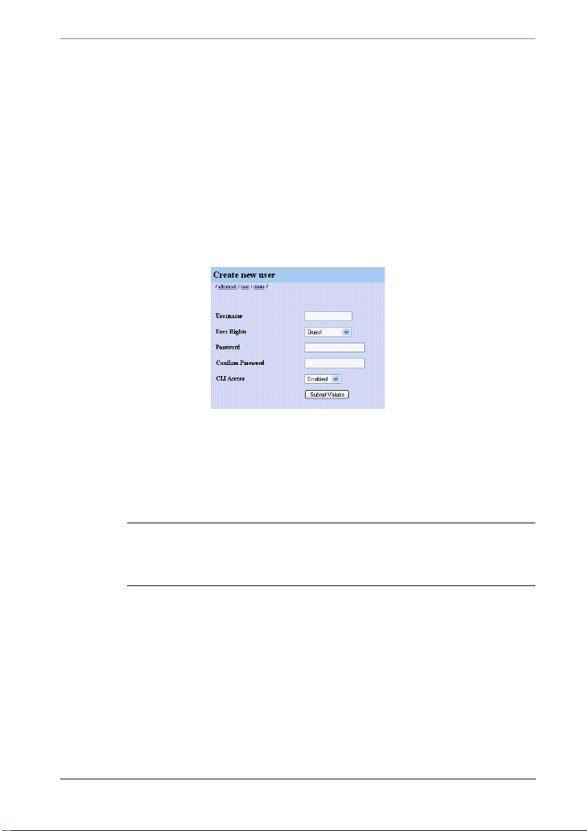
Create New Privileged Administrator
Create New Privileged Administrator
Although the SecureWall firewall is activated by default, blocking access to the
Firewall for configuration from the Internet, it is a good idea to change the default
username of “multicom”.
To change the Administrator Username and Password on the MultiCom Firewall
you will need to use a web browser to goto http://10.0.0.1/advanced/user/create/
(where 10.0.0.1 is the IP address of the LAN interface of the Firewall). Enter in a
new Username and Password and select the User Rights “Privileged” with CLI
Access enabled. When you are finished click “Submit Values”.
When the new “Privileged” user is created, the default user “multicom” is
disabled. This means that only the new user will have the right to configure the
MultiCom Firewall. If you forget your username and password, you will have to
reset the MultiCom Firewall back into its default configuration and reload the
configuration file from a backup copy.
NOTE - When the first new Privileged user is created the multicom
user will be deactivated and you will need to authenticate again using
the new username and password that you created.
The Reference Manual has descriptions of all user and permission options.
Quick Interface Configuration
If you want to make a quick change to an interface’s configuration you will need
to use a web browser to go to the LAN interface (by default http://10.0.0.1).
Select interface from the menu (WAN, LAN, DMZ, DSL, WLAN) and change
the configuration on the following pages. When you are finished you will have
the option to either
MultiCom Firewall User’s Manual 69
Page 70

Chapter 3 Getting Started
• 'Apply Configuration' to test a new configuration but not save it. Rebooting
the Firewall will return the Firewall to its previous configuration.
• 'Apply Configuration and Save as Boot config' to activate and permanently
save your configuration
Testing Your Configuration
The process of communication to the Internet works as follows when your
MultiCom Firewall and workstation computers are configured properly.
1. Your computer makes a request to reach the Internet or a service from the
Internet.
2. This request is sent to the network through your ethernet card/interface.
3. Your ethernet card/interface forwards this information to the MultiCom
Firewall
4. Your MultiCom Firewall takes this info rm ation and forwards it to your
modem or directly to the ISP if the modem is in “bridge” mode
5. your modem, unless already connected will dial your Internet Service
Provider, authenticate your user name and password and then send
information request to the Internet
The information that you requested will follow the same route back (in the
opposite order) to reach the computer making the request. In most cases you will
either get the information that you received, get a response that it was not found,
or because of network congestion be told that your request has timed-out and was
dropped.
To test that your connections are working correctly you can open your preferred
Internet browser (Netscape Navigator or Microsoft's Internet Explorer) and type
in a web address.
NOTE — please hit the refresh page on your browser to be sure that
you are getting information from the Internet directly instead of from a
web page saved to your hard disk. You should also notice the lights on
your MultiCom Firewall blinking.
70 MultiCom Firewall User’s Manual
Page 71
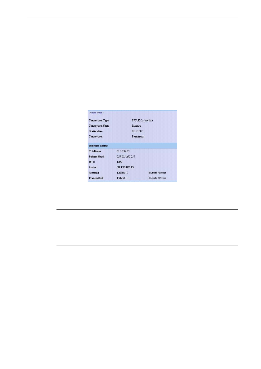
Testing Security
Unless your modem is already connected it will make the phone call now and
retrieve the information that your computer requested. If you are able to reach the
Internet then everything is working properly. If you have problems first check
that everything is plugged in, go over this chapter again, check the
Troubleshooting chapter, and finally consider calling the Technical Support of
where you purchased your MultiCom Firewall.
Diagnostics and status information on this connection is available from the
MultiCom web server at http://10.0.0.1/status/wan/ and from the DHCP or PPP
tab of the Configurator software’s Monitor window.
Don't forget to register your MultiCom Firewall and consider reading up on the
more advanced options available.
CAUTION — A request to the Internet may be made without your
being aware of it. These requests could inadvertently open your
network connection and cause you additional phone. Check the
Troubleshooting chapter for more information on Internet connections
For more detailed testing suggestions for your configuration and firewall check
the Lightning-Linux Reference Manual.
Testing Security
Here are some web sites that offer free security scanning of your Intern et
connection. There are many such sites available on the Internet.
http://www.dslreports.com/scan
http://www.hackerwhacker.com/
http://scan.sygatetech.com/
MultiCom Firewall User’s Manual 71
Page 72

Chapter 3 Getting Started
http://security1.norton.com/us/intro.asp
http://www.mcafeeasap.com/intl/EN/content/managed_services/vulnerability.asp
Testing Connection Speed
Here are some web sites that offer free bandwidth tests of your Internet
connection. There are many such sites available on the Internet.
http://www.zdnet.co.uk/misc/band-test/speedtest50.html
http://www.testmyspeed.com/internationalspeedtests.htm
http://www.dslreports.com/stest
http://www.gibroadband.com/pages/speedtest.asp
http://bandwidthplace.com/speedtest/
http://www.itzalist.com/com/dsl-speed-test.html
Registering Your Firewall
Registering your firewall allows you to keep up to date with the latest
developments for your product. Additionally registration takes away the burden
of keeping proofs of purchase (for upgrades or repairs) as our database will take
care of that for you. Now is a good time to do it while you have your receipts and
serial number readily available.
For online registration go to http://www.lightning.ch/register.html
72 MultiCom Firewall User’s Manual
Page 73

Maintenance
While basic security is enabled as soon as you plug your MultiCom Firewall
firewall between your modem and your network, a well running network requires
regular maintenance. A poorly maintained network may suffer from network
performance loss or worse such as network failure (especially when you need it
most.)
Any number of factors can affect the way your network runs — new software
installations, misconfigurations of hardware, and even electromagnetic
interference can all cause serious changes in the way data travels through your
network.
Chapter 4
Just as with any emergency, preparation will minimize the effect on your business
and peace-of mind. Your MultiCom Firewall has been equipped with numerous
tools to assist in your maintenance needs.
• Checking System Status
—Using the Configurator software
—Using the built-in web server
—Using shell commands to directly log into the firewall
• Configuration
—Backup the Configuration
MultiCom Firewall User’s Manual 73
Page 74
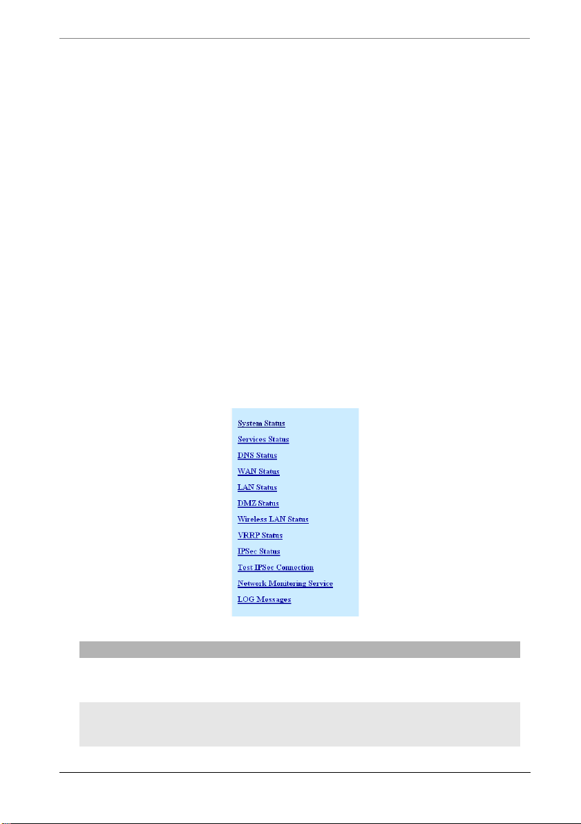
Chapter 4 Maintenance
—Restoring the Configuration
• Keep up to date
—update the firmware
—read about current networking exploits
Web Server Status Reports
By using a web browser you can get status information of ARP and routing
tables, interfaces, memory and CPU loads, uptime and more. You just type in the
IP address of the firewalls LAN or WAN interface (by default http://10.0.0.1),
enter any necessary user names and passwords (by default user=“multicom” and
there is no password). You can print this information out using your web
browser's print functions.
Starting in Lightning-Linux 3.4 the web server provides direct status information
of the Firewall, services, interfaces, and logged events. Simply select the
STATUS link in the menu. This page is shown below.
Tools Function
System Status Shows system firmware version, device type, serial
number, installed options, system uptime and CPU
load
Services Status Shows the status of the ARP Proxy, DNS Proxy,
DynDNS, FTP, NTP, RIP, SNMP and Syslog
services.
74 MultiCom Firewall User’s Manual
Page 75

Web Server Status Reports
Tools Function
DNS Status Shows the current Domain Name Servers
ADSL Status Shows ADSL connection diagnostics and PPP
configuration on the ADSL interface
WAN Status Shows WAN interface diagnostics such as MAC
address, ethernet speed, and IP parameters. If the
interface is a DHCP client you will have a button to
renew the DHCP lease. If it is a PPPoE Manual/ Dial
on Demand connection you will have the option to
Connect or Disconnect.
LAN Status Shows LAN interface diagnostics such as MAC
address, ethernet speed, and IP parameters. It will
also show if a DHCP server is active on the interface
and offer the option to see existing DHCP Leases.
DMZ Status Shows DMZ interface diagnostics such as MAC
address, ethernet speed, and IP parameters. It will
also show if a DHCP server is active on the interface
and offer the option to see existing DHCP Leases.
Wireless LAN
Status
VRRP Status If the High Availability option has been installed this
IPSec Status Shows a table of existing IPSec connections and
Test IPSec
Connection
Network
Monitoring
Service
LOG Messages Event log of activities occurring on the MultiCom
All of the web servers status screens are shown in the Web Server Screens
Appendix in the Reference Manual.
Shows the Wireless Interface diagnostics. This is the
window where the user can see the WLAN status and
state of each hardware interface, the current
configuration of the selected interface, the broadcast
level.
table shows the status of VRRP on each interface.
statistics about each connection when the IPSec
Option is installed.
Allows the testing of each active IPSec connection
when the IPSec Option is installed.
Shows a table of TCP networking services that are
being monitored by the MultiCom Firewall when the
Network Monitoring Option is installed.
Firewall such as loading new configurations,
activation or deactivation of IP services, errors. This
is the same event log as can be seen in the Monitor
software.
MultiCom Firewall User’s Manual 75
Page 76

Chapter 4 Maintenance
Below are some of the direct web links to commonly used diagnostic information
in older firmware versions. The following examples use the firewall’s default IP
address of 10.0.0.1. If your firewall is using a different IP address use that in
place of the 10.0.0.1.
Table 7: Common web server diagnostics pages for firmware 3.0-3.3
MultiCom Serial number http://10.0.0.1/config/system/hardware/
Software version http://10.0.0.1/config/system/software/
LAN status http://10.0.0.1/config/interface/ethernet[LAN]/stat
LAN DHCP server leases http://10.0.0.1/config/interface/ethernet[LAN]/ip/d
WAN status http://10.0.0.1/config/interface/ethernet[WAN]/stat
WAN DHCP client status http://10.0.0.1/config/interface/ethernet[WAN]/ip/
PPPoE status http://10.0.0.1/config/i nterface/ppp[PPPoE]/status/
PPPoE IP status http://10.0.0.1/config/interface/ppp[PPPoE]/ipcp/st
PPPoE Link status http://10.0.0.1/config/interface/ppp[PPPoE]/lcp/sta
Available PPPoE servers http://10.0.0.1/config/interface/ppp[PPPoE]/pppoe/
PPTP Status http://10.0.0.1/config/interface/ppp[PPTP]/status/
PPTP Link status http://10.0.0.1/config/interface/ppp[PPTP]/lcp/stat
ARP entries http://10.0.0.1/config/arp/status/arp_entry/
DNS servers used http://10.0.0.1/config/ip/dns/status/nameserver/
us/
hcp/server/status/leases/
us/
dhcp/client/status/
atus/
tus/
server_list/
us/
Using the above links will help you to find where a problem may be. For
example, if you have checked the WAN status or the PPPoE status and they both
have IP addresses assigned to them they are functioning normally and your
problem is probably somewhere else.
Monitor Status Reports
The Configurator software for your MultiCom Firewall includes detailed
monitoring windows. These diagnostic utilities give you the current st ate of your
firewall whether it is on a local or remote network.
76 MultiCom Firewall User’s Manual
Page 77
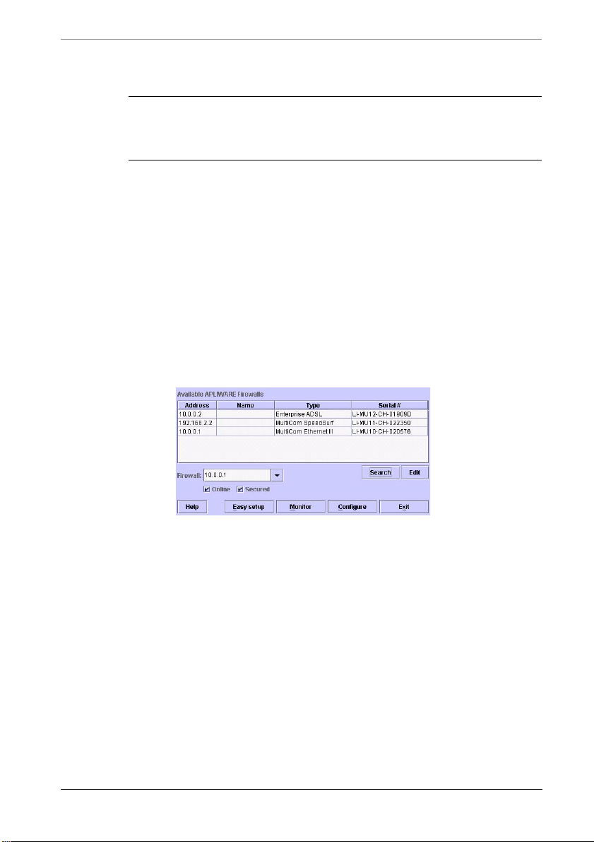
Monitor Status Reports
CAUTION - when accessing remote MultiCom Firewalls on the
Internet it is recommended to always use the Configurator in
“Secured” mode to protect the information exchanges.
With the monitoring options you will be able to get information on the System
status, ARP tables, DNS, each interface, DHCP services, installed routes and
more.
Optionally you could also have a syslog server set to listen for info level
announcements from the MultiCom Firewall and watch for alerts, warnings,
notices and other information.
1. To reach the monitoring screens of the Configurator you will need to first
start the Configurator from CD, hard disk or a remote drive. (see the section
on Starting Easy Setup or Installing the Configuration Software if you need
assistance in starting the Configurator).
2. Click search to search for the MultiCom Firewall on your local netw ork or
just enter the IP address of the firewall you wish to monitor
3. Be sure “Online” and “Secured” buttons are checked and click on the
Monitor button
4. You should now have arrived at the screen titled Monitor. Depending on
what sort of diagnostics you are looking for, go to the appropriate screen.
MultiCom Firewall User’s Manual 77
Page 78
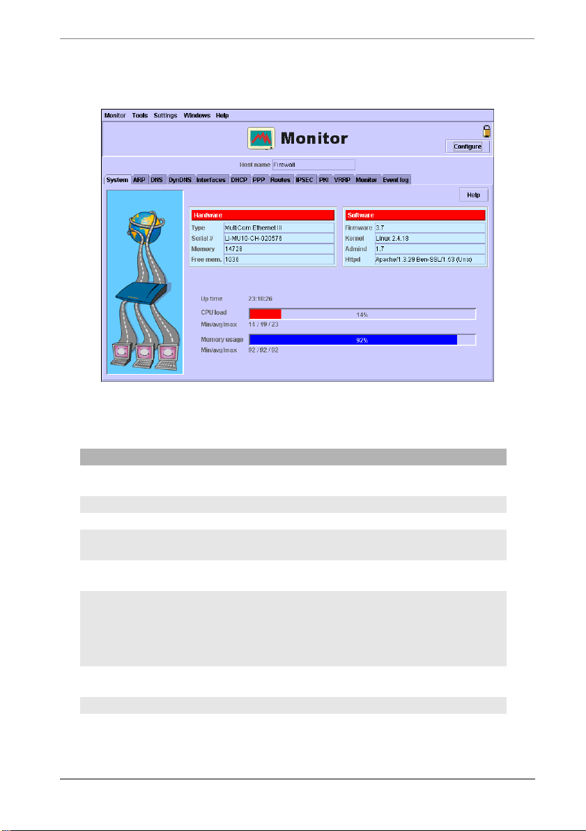
Chapter 4 Maintenance
You should now have arrived at the screen titled Monitor. Depending on what
sort of diagnostics you are looking for, go to the appropriate screen.
Panels Available Information
System General information about the hardware, firmware
and work load of your MultiCom Firewall.
ARP The currently active ARP table in the firewall
DNS The currently active DNS servers for the firewall
Dynamic DNS The current status of a Dynamic DNS configuration if
Interfaces Status of each interface port (LAN/WAN), identifying
DHCP Client Window— shows all of the configuration data
PPP Describes current status of PPPoE interfaces if they
Routes The currently active routes in your firewall
Bridges Displays information about the LAN-WLAN bridge
78 MultiCom Firewall User’s Manual
one exists
information, and data traffic reports
received from a DHCP server
Server Window — shows currently assigned IP
addresses and their lease times.
are active
of your MultiCom Firewall when the Bridge is
activated.
Page 79
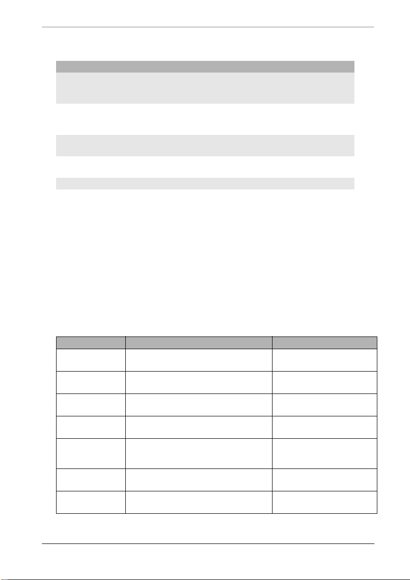
Telnet/ Console Status Reports
Panels Available Information
IPSec Status of selected IPSec connections and summary of
all IPSec connections (when IPSec options are
installed)
PKI Status of PKI Keys, Certificates and Certificate
VRRP Status of High Availability on each interface (when
Monitor Status and delay of each listed service host (when
Event Log Events being generated by the MultiCom Firewall
Revocation Lists installed on the Firewall (when
IPSec optionsa are installed)
the High Availability option is installed)
Network Monitoring options are installed)
Telnet/ Console Status Reports
By logging into the Firewall’s telnet, SSH telnet or console interface (check your
User’s Manual to see if your firewall has a console interface) you can run the
“info” commands to get a text status information of particular parts of the
MultiCom Firewall and its software.
This used with telnet scripting utilities (such as the Expect software for Linux and
Windows, or CatTools for Windows at http://www.kiwisyslog.com) for reports
and automated management of the MultiCom Firewalls.
Table 8: Common telnet/ console diagnostics
Description Commands Sample output
last error
causing reboot
MultiCom
Serial number
Software
version
LAN status /: info interface ethernet LAN
LAN IP
Address
/: backtrace only available in 3.5+
/: info system hardware
serial_number
/: info system software firmware firmware = 3.6
status status
/: info interface ethernet LAN
status ip_address
serial_number =
LI-MU7-CH-0200D2
status = UP RUNNING
ip_address = 10.0.0.1
LAN DHCP
Mode
/: info interface ethernet LAN ip
netmask
/: info interface ethernet LAN ip
dhcp mode
MultiCom Firewall User’s Manual 79
netmask = 255.0.0.0
mode = server
Page 80

Chapter 4 Maintenance
Description Commands Sample output
LAN DHCP
server leases
WAN status /: info interface ethernet WAN
WAN DHCP
client status
PPPoE status /: info interface ppp PPPoE status
PPPoE IP
address
PPPoE IPCP
info
PPPoE Link
status
/: info interface ethernet LAN ip
dhcp server status leases
/: info interface ethernet LAN ip
dhcp server status leases 0 ip
/: info interface ethernet LAN ip
dhcp server status leases 0
hw_address
/: info interface ethernet LAN ip
dhcp server status leases 0 starts
/: info interface ethernet LAN ip
dhcp server status leases 0 ends
/: info interface ethernet LAN ip
dhcp server status leases 0
hostname
status status
/: info interface ethernet WAN ip
dhcp client status state
status
/: info interface ppp PPPoE status
ip_address
/: info interface ppp PPPoE ipcp
status state
/: info interface ppp PPPoE lcp
status info
indexes: 0 1 2 3
ip = 10.0.0.17
hw_address =
00:c0:f0:4c:a7:90
starts = 4 2001/06/28
13:24:06
ends = 4 2001/06/28
14:24:06
hostname =
"NT-workstation"
status = UP RUNNING
state = Assigned
status = UP RUNNING
ip_address =
212.147.17.76
state = UP
state = DOWN
info = ""
info = CHAP
authentication failed
PPPoE DNS
assigned
servers
80 MultiCom Firewall User’s Manual
/: info interface ppp PPPoE ipcp
status primary
/: info interface ppp PPPoE ipcp
status secondary
info = Timeout sending
Config-Requests
info = Endpoint not
connected
primary =
212.147.10.10
secondary =
212.147.0.1
Page 81
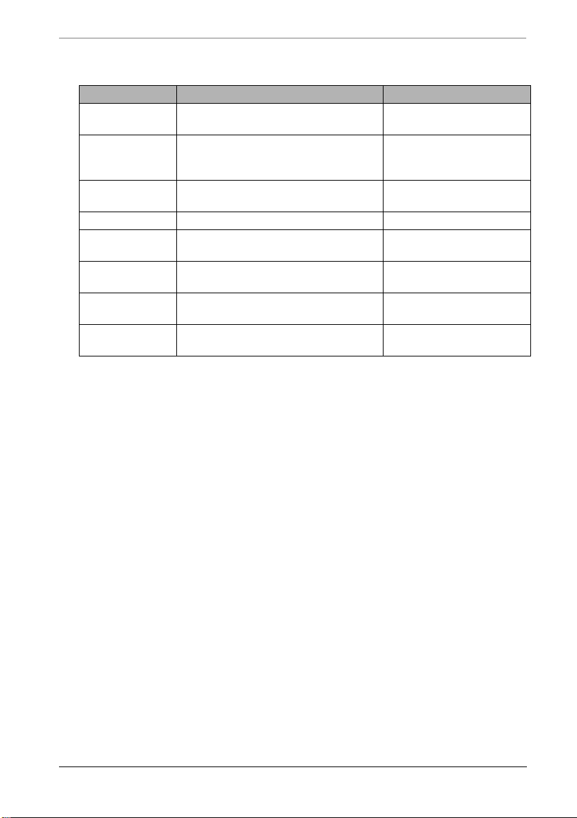
Telnet/ Console Status Reports
Description Commands Sample output
Available
PPPoE servers
ARP entries /: info arp status arp_entry indexes: 0 1 2
DNS servers
used
The console interface is useful if you may have blocked your Ethernet interface
access or think there may be a problem with your Ethernet network (your
computer’s Ethernet interface, a hub/ switch, cabling). Simply configure your
workstations serial port according to the Console Configuration in the Hardware
Specification chapter and plug in the serial cable to your MultiCom Firewall and
workstation’s 9pin serial port. This gives direct access to the firewall.
/: info interface ppp PPPoE pppoe
server_list
/: info interface ppp PPPoE pppoe
server_list 0
access_concentrator_name
/: info interface ppp PPPoE pppoe
server_list 0 service_name
/: info arp status arp_entry 0
hw_address
/: info arp status arp_entry 1
hw_address
/: info ip dns status nameserver 0
ip
/: info ip dns status nameserver 1 ipip = 192.168.1.116
indexes: 0 1 2
access_concentrator_na
me = ipc-lsp690-r-l c-01
service_name = Any
hw_address =
00:C0:F0:57:4A:6D
hw_address =
00:C0:F0:4C:A7:90
ip = 192.168.1.115
MultiCom Firewall User’s Manual 81
Page 82

Chapter 4 Maintenance
Table 9: Common telnet/ console commands
Description Commands
ENABLE IPSEC set security ipsec enabled=true
saveconfig current
DISABLE IPSEC set security ipsec enabled=false
SEE IPSEC
CONNECTIONS
STOP AN IPSEC
CONNECTION
START AN IPSEC
CONNECTION
ENABLE
SECUREWALL
DISABLE
SECUREWALL
ENABLE FILTERING set ip filtering enabled=true
DISABLE
FILTERING
ENABLE FILTERING
OBJECTS
DISABLE
FILTERING
OBJECTS
ENABLE DNS
PROXY
DISABLE DNS
PROXY
ENABLE RIP set routing ip rip enabled=true
DISABLE RIP set routing ip rip enabled=false
ENABLE FTP set ip ftp server enabled=true
DISABLE FTP set ip ftp server enabled=false
ADD SYSLOG
SERVER
ENABLE SYSLOG
DEBUG OUTPUT
saveconfig current
ipsec
ipsec terminate <connection name>
ipsec initiate <connection name>
set interface ethernet WAN ip nat securewall=true
saveconfig current
set interface ethernet WAN ip nat securewall=false
saveconfig current
saveconfig current
set ip filtering enabled=false
saveconfig current
set ip filtering_objects enabled=true
saveconfig current
set ip filtering_objects enabled=false
saveconfig current
set ip dns proxy enabled=true
saveconfig current
set ip dns proxy enabled=false
saveconfig current
saveconfig current
saveconfig current
saveconfig current
saveconfig current
add ip syslog server 0
set ip syslog server 0 address=10.0.0.2 level=debug
saveconfig current
eventdebug start
82 MultiCom Firewall User’s Manual
Page 83
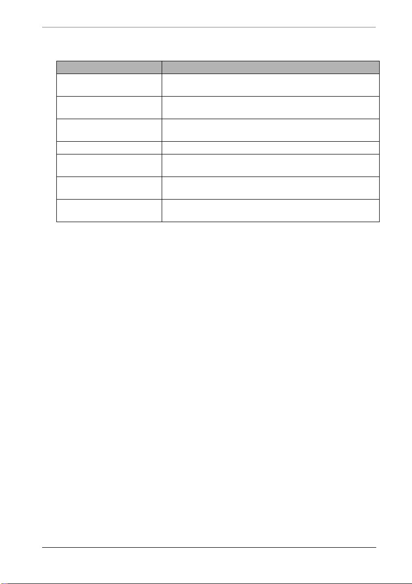
Error Messages
Description Commands
DISABLE SYSLOG
DEBUG OUTPUT
ENABLE SSH set security access ssh enabled=true
DISABLE SSH set security access ssh enabled=true
REBOOT reboot
ENABLE TELNET set security access telnet enabled=true
DISABLE TELNET set security access telnet enabled=false
RENEW DHCLP
CLIENT ON WAN
eventdebug stop
saveconfig current
saveconfig current
saveconfig current
saveconfig current
dhcpclient WAN renew
Error Messages
In addition to the Web server, Monitor and Telnet/ Console Status reports, the
MultiCom Firewall has 3 other methods for informing you what is happening and
if something is wrong.
• LED light messages
• Syslog messages
• SNMP messages
LED Light Messages
The LED lights on the front of your MultiCom Firewall are designed to give you
a quick update on the current status of your firewall. Some of the things you can
find out from your Interface LED lights (labeled LAN, WAN or DMZ) are
• If an ethernet interface is properly connected (a solid green light)
• If an interface is not connected (a solid red light)
• If data is traversing the interface (when the active port blinks orange, data is
traveling through that interface)
• If there are collisions occurring on the firewall (the light blinks red)
Starting with Lightning-Linux 3.3 the Security LED is also functional and will
show:
MultiCom Firewall User’s Manual 83
Page 84

Chapter 4 Maintenance
• If SecureWall is activated (a solid green light)
• If SecureWall is deactivated but SPI Filtering is activated (a solid orange
light)
• If both SecureWall and Filtering are deactivated (a solid red light)
Syslog Messages
Syslog messages can be configured to be sent from the firewall to a syslog server.
Please refer to the SNMP & Syslog chapter of the Reference Manual if you wish
to use this functionality.
Some common, Syslog messages are:
• Telnet, ssh, and web logins, logouts and failures
• Failed and successful attempts to save a configuration file to the firewall
• IPSec activity
• Network Monitoring activity
• Network Monitoring activity
• Email activity
• DHCP activity
• PPPoE activity
• PPTP activity
• Stateful Packet Inspection (SPI) activity
• SecureWall dropped packets
• Startup of firewall
SNMP Messages
The MultiCom firewall can be configured to respond to SNMP requests from
SNMP client software. Please refer to the SNMP & Syslog chapter of the
Reference Manual if you wish to use this functionality.
Some common SNMP requests will show:
• Hostname and Linux firmware version
• Uptime
• Customizable location and contact information
• detailed information on each Ethernet interface
84 MultiCom Firewall User’s Manual
Page 85
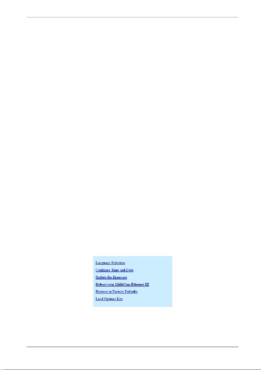
Configurator messages
• detailed IP/UDP/ICMP packet statistics
• connection state for ports on the MultiCom Firewall and IP address of who is
using that port (for instance for telnet or SSH CLI access)
• statistics on SNMP data requests
• route and ARP data stored on the MultiCom Firewall
Configurator messages
If you choose to use the Configurator Software, it also has a log window that lists
successful activity and errors of the Configurator software. These error messages
will explain if anything has gone wrong while using the Configurator software
and will help identify what is causing the problem. The information in this
window can be cut and paste for printing or emailing to Technical Support.
To see the Log window click on the Tools Menu and select the Show Log
command.
The error messages from the Configurator allow you to cut and paste the text in
most operating systems. Check with your operating system for it’s method of
cutting and pasting text into different windows.
Web Server Toolbox
The MultiCom Firewall offers a live toolbox for common maintenance activities.
You just type in the IP address of the firewalls LAN or WAN interface (by default
http://10.0.0.1), enter any necessary user names and passwords (by default
user=“multicom” and there is no password), and click on the Toolbox menu item.
The following tools are available:
MultiCom Firewall User’s Manual 85
Page 86
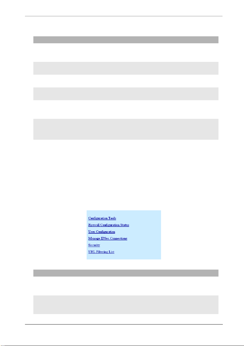
Chapter 4 Maintenance
Tools Function
Language
Selection
Configure Time
and Date
Update the
Firmware
Reboot the
Firewall
Restore the
Factory Defaults
Load Options Key Loads purchased option keys to activate additional
Choose which language to see the web interface in or
choose AUTO to select the language based on the
language the web browser is configured to use.
Enter the new date and time for the MultiCom
Firewall
T ells the MultiCom Firewall where the upgrade
firmware is and to start the upgrade process.
Reboots the MultiCom Firewall using the
configuration in the “boot” memory position
This will delete all passwords, security parameters,
option keys and configuration files and reboot with
the factory default configuration
features like Virtual Private Networks using IPSec or
SSH Port Forwarding.
Web Server Advanced Tools
The MultiCom Firewall offers an configuration window for advanced
maintenance activities. You just type in the IP address of the firewalls LAN or
WAN interface (by default http://10.0.0.1), enter any necessary user names and
passwords (by default user=“multicom” and there is no password), and click on
the Advanced menu item. The following tools are available:
Tools Function
Configuration
Tools
Firewall
Configuration
Status
86 MultiCom Firewall User’s Manual
Edit a live configuration, upload a new configuration
from a text file, or save the current configuration to a
text file.
Advanced statistics about IP Services, Interfaces,
Security, ARP, Routing, and the current system
hardware and software.
Page 87
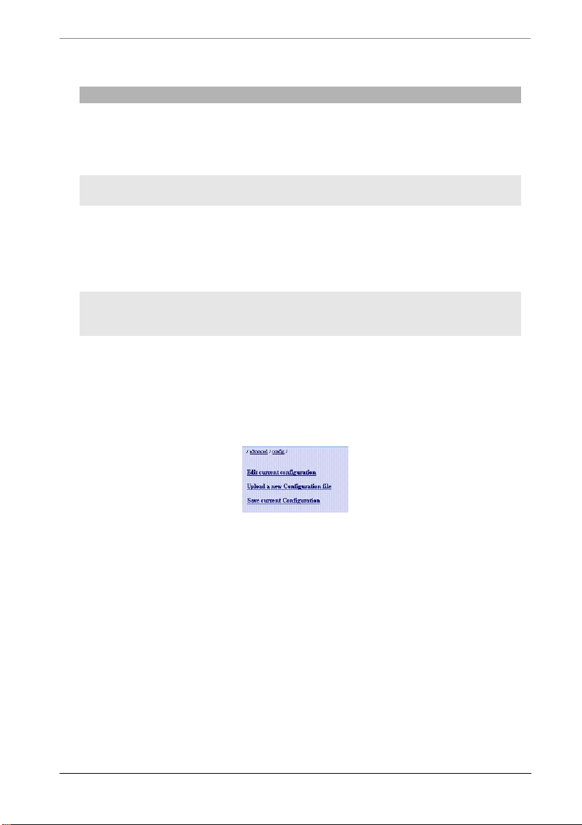
Backup Your Configuration
Tools Function
User
Configuration
Manage IPSec
Connections
Security Edit a live security configuration, upload a new
URL Filtering
List
Create, edit or delete users and permissions on the
MultiCom Firewall. Additionally you can login as a
different user from this window. See the Reference
Manual chapter on Concepts for explanations on the
different users and rights.
Enable, disable or remove IPSec connections.
Requires an IPSec option to be installed.
security configuration from a text file, or save the
current security configuration to a text file. The
security configuration contains the keys for creating
IPSec tunnels. Additionally configure IPSec PKI
keys and certificates here.
Enable or disable URL Filtering and directly edit the
URL keyword list. Additional options are available
when using the Configurator software.
Backup Your Configuration
It is important to maintain a backup of your configuration file in case of
emergencies. This can easily be done with the built-in web server.
1. Start web browser software and go to http://10.0.0.1/advanced/config/ where
10.0.0.1 is the IP Address of the MultiCom Firewall’s LAN interface.
2. Click on “Save current configuration” (if a question appears asking what to
do with the file select “Save this file to disk”.)
3. Enter in the name you want to save the configuration backup under and the
directory location.
4. Click Ok
The file saved is a text file that you can save to a floppy or attach to an email.
MultiCom Firewall User’s Manual 87
Page 88

Chapter 4 Maintenance
Restoring A Configuration
When you need to restore a saved configuration file to your MultiCom Firewall
firewall you will use the built in web server or the included Configurator
software.
1. Start web browser software and go to http://10.0.0.1/advanced/config/upload/
where 10.0.0.1 is the IP Address of the MultiCom Firewall.
2. Enter the directory and name where the saved configuration file resides.
Optionally use the Browse... button to search for the file on your hard disk.
3. Click Submit Values
NOTE - During the application of a new configuration or while an
MultiCom Firewall is loading a new configuration during bootup the
routing table is blocked. This allows all of the rules to be loaded
before traffic can move through the firewall.
Updating Your Firmware
Because your MultiCom Firewall has been equipped with flash memory it is
possible for you to update it with a newer operating system (also known as
firmware) than was available when you purchased it.
NOTE — Contact your distributor or check the Lightning web site for
notifications on the latest firmware. Additional charges may apply.
Upgrading the firmware on your MultiCom Firewall requires you to access the
web server on the firewall. Your configuration files will remain untouched
however the factory default configuration may change (this configuration is
accessed when rebooting the Firewall while holding down the config button.)
Your MultiCom Firewall will reboot and be offline for up to 5 minutes during the
upgrade process. Be sure that your network can afford to be without Internet
access for at least 5 minutes and that there are no important data transfers
occurring during this time.
88 MultiCom Firewall User’s Manual
Page 89

Updating Your Firmware
CAUTION - Please note, that if the power is interrupted during the
upgrade process your MultiCom Firewall could become unusable and
require repairs from your local distributor. Continue at your own risk.
To install the latest firmware follow the steps below. Please check the Support
website for the latest version of the MultiCom Firmware Upgrade instructions.
MultiCom Firewall User’s Manual 89
Page 90
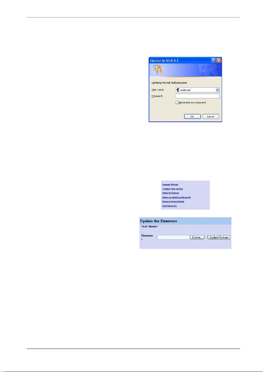
Chapter 4 Maintenance
Table 10: Steps to Upgrade MultiCom Firmware
1. Download the latest firmware
to your computer
2. Access the MultiCom Firewall
web server. Simply type in the
IP Address of the MultiCom
Firewall into an Internet
browser which is connected to
the same network as the
MultiCom (usually this is the
LAN interface).
3. Type in your username and
password (by default the
username is "multicom" and
there is no password.)
4. Select Toolbox (or MultiCom
Tools in firmware versions
before 3.4)
5. Select Update the Firmware
6. Type in the location of the new
firmware file or click
Browse to
find the file on your hard disk.
If you use
Browse you may
need to choose “All Files (*.*)
in the Type: box if you cannot
see the firmware.
7. Select Update Firmware after
you have selected the firmware
file to update with.
90 MultiCom Firewall User’s Manual
Page 91
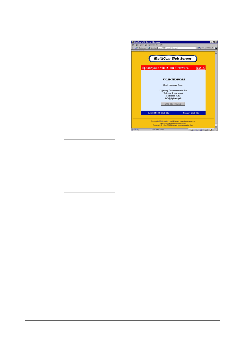
8. The Web server will verify that
the firmware is indeed valid
before writing it to the device.
If it is valid you will see the
button
Write New Firmware,
press this button. Otherwise
you are asked to reload the
firmware.
If the web server gives you an
error or does nothing then try
using a different web browser or
check with your distributor for
another copy of the firmware.
NOTE - this step is skipped in
firmware versions 3.1 and
higher. If the firmware is
good you will jump to step 9
and write the new firmware. If
the firmware is bad your router
will reboot with the previous
firmware.
Steps to Upgrade MultiCom Firmware
MultiCom Firewall User’s Manual 91
Page 92
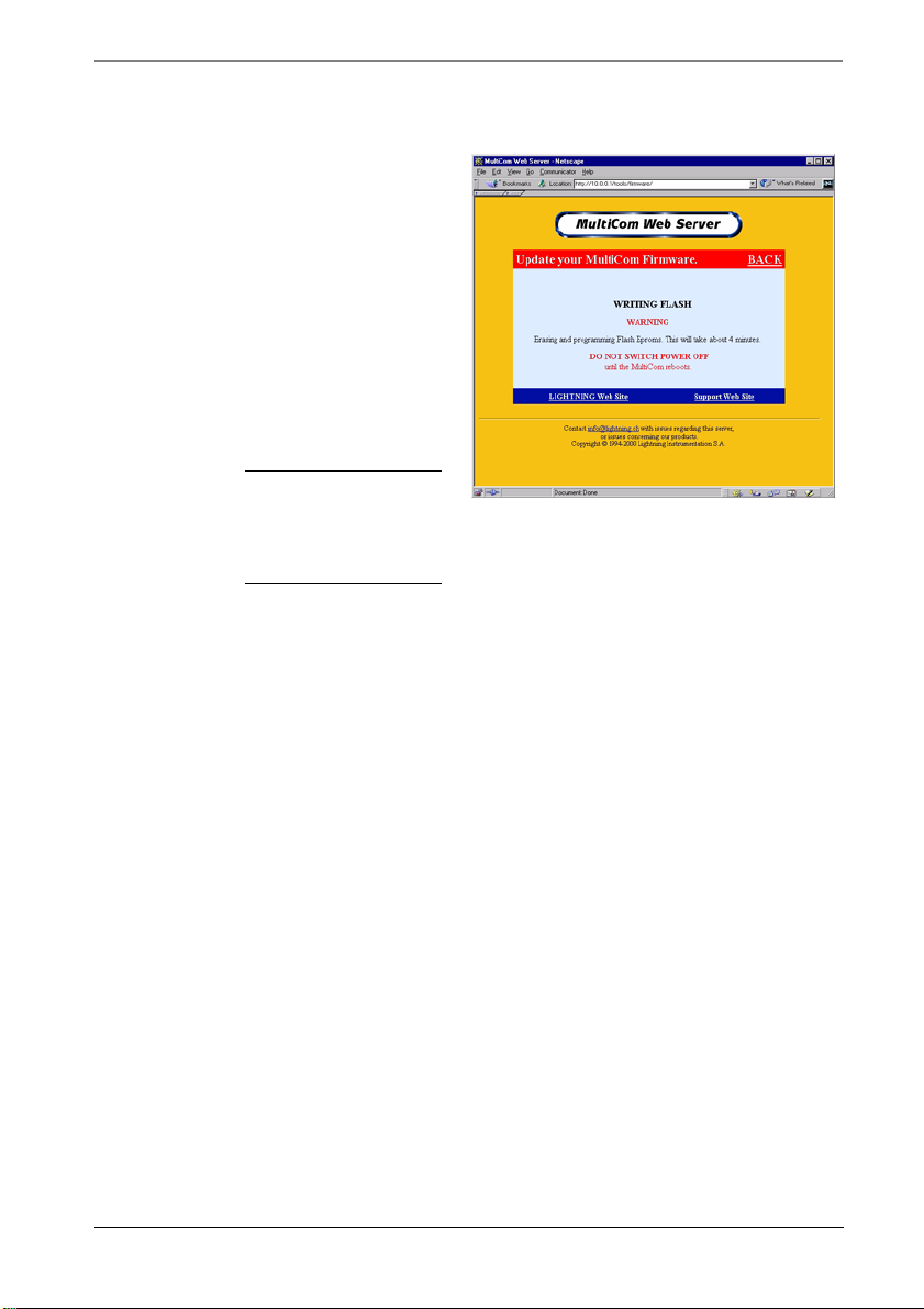
Chapter 4 Maintenance
9. The MultiCom Firewall now
begins the process of erasing
the old firmware and writing
the new firmware. Wait for
the MultiCom Firewall to
reboot with the new firmware
upgrade. The lights on the
front of the device will change
colors during the upgrade
process and will stop blinking
after the MultiCom Firewall
has rebooted.
WARNING - While the firmware
upgrade is being written do not
interrupt the power to the
MultiCom Firewall!
10. You are finished. Verify that
your new version of
Lightning-Linux firmware is
currently installed in your
MultiCom Firewall. In your
web browser go to
http://10.0.0.1/config/system/so
ftware/ where 10.0.0.1 is the IP
Address of your MultiCom
Firewall.
LED Status During Upgrade
Starting with Lightning-Linux 3.1 the leds on the front of your MultiCom
Firewall indicate the status of the firmware upgrade according to the table below.
92 MultiCom Firewall User’s Manual
Page 93
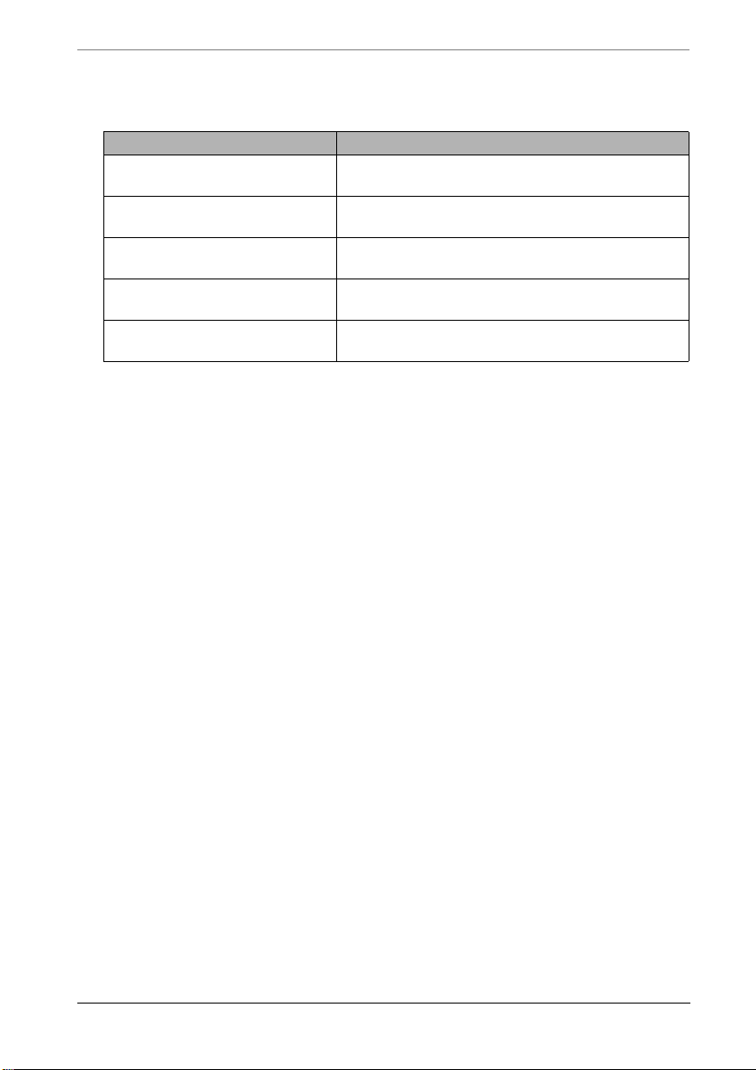
LED Status during upgrade
Table 11: LED Status during upgrade
Status Description
Checking the validity of the
firmware
Erasing existing flash
memory
Writing the new firmware
into the flash memory
Error while erasing the
existing flash memory
Error while writing the new
firmware to flash memory
All of the leds are lit green except the power
led which is blinking green and black.
All of the leds are lit green except the power
led which is blinking orange and black.
All of the leds are lit green except the power
led which is blinking orange and green.
All of the leds are blinking red and orange.
All of the leds are blinking red and black.
Troubleshooting Firmware Upgrade
If power is interrupted during the flash upgrade process the existing firmware
could become corrupted. Normally this will be evident because the lights are
frozen every time you reboot the MultiCom Firewall and it will not respond to
normal networking activity. To recover from this please contact your local
distributor. If after a reboot you have the same firmware version that was
previously installed then there was a problem with the firmware upgrade. Try
reinstalling it again, rebooting the MultiCom Firewall into the default
configuration and then try reinstalling again, download or contact your distributor
for another copy of the firmware.
Remember that you will need to upgrade the Config urat or software to the same
version of the firmware that you just installed.
MultiCom Firewall User’s Manual 93
Page 94

Chapter 4 Maintenance
94 MultiCom Firewall User’s Manual
Page 95

Troubleshooting
When you are running a network (whether one computer connected directly to the
Internet or many) it is possible that problems can come up. Maybe the network is
giving you slow responses, some devices or computers are not reachable, you are
reaching the wrong computer or your filters do not seem to be working. This
chapter will help you fix some common networking issues.
To correctly fix the problem the source of it must be found. In networking this is
especially true because the problem may not necessarily point you toward the
answer (for instance a bad DNS server would stop you from reaching web
addresses but not if you only used the IP address.)
Chapter 5
There are two questions you must always check...
1. Were the instructions followed correctly
2. Has anything recently changed before the problem occurred? (for instance
are you using new network drivers, new workstation on the network...)
If these two questions do not help you find the problem then it is time to do some
troubleshooting with the firewall itself.
MultiCom Firewall User’s Manual 95
Page 96

Chapter 5 Troubleshooting
Basic Things To Check
Always check that your cabling and basic connections are functioning correctly
for the ports you are using. If there is a problem moving your data back and forth
at this level then higher level troubleshooting will be ineffective.
• Are the cables correct (crossed cable versus straight cable.)
• Are the interface lights (LAN, WAN, DMZ) on the firewall green when the
cables are plugged into your ethernet card/interface or xDSL, cable or
wireless modems?
• Are the lights on the hub or ethernet interface of the device green where the
firewall cable is plugged in.
These answers must be yes before you do any more in-depth troubleshooting. If
there are problems here and you are using a hub, be sure to verify that you are not
using the uplink port. Otherwise try verifying the ethernet device is functioning
correctly and try switching the ethernet cable to one that you know is good.
If all of the physical connections are good (as tested above) the next steps is to
verify that you can:
1. from your computer, communicate with the LAN interface of the MultiCom
Firewall
2. from the MultiCom Firewall, communicate with your ISP
3. from your computer, communicate with the Internet
TIP - A simple troubleshooting step is to reboot the MultiCom Firewall
and try again. If all else fails, reset the Firewall into the default mode
as described in the “Resetting the Default Configuration” Section on
page 105. Then reconfigure it using the Easy-Setup.
After checking these basic issues please continue to the Common Network
Problems on the next page which describe some common problems that may
occur on your Local Network.
Finally, look at the sections below that corresponds to the type of connection that
your ISP uses - DHCP, PPPoE, PPTP. These sections will explain common
problems on the Remote Network that connects you to your ISP and the Internet.
If you are still having problems consider calling technical support.
96 MultiCom Firewall User’s Manual
Page 97

Common Local Network Problems
Common Local Network Problems
Please look over these common reasons for networking problems. Additionally,
please check the section below relating specifically to your type of connection
(DHCP, PPPoE, PPTP, Static IP addresses.)
Once you know that your cabling is okay it is time to ask some more detailed
questions.
• Is the modem working? (check the diagnostics that came with the modem,
maybe you can check LED displays or communicate directly with the
modem)
• Is TCP/IP installed on your computer? (if you can ping 127.0.0.1 in a telnet
window/ DOS window TCP is installed)
• Is the firewall reachable? (using the ping command for instance in a telnet
window/ DOS window and try PING 10.0.0.1 where 10.0.0.1 is the IP
Address of your MultiCom Firewall’s LAN interface.) Sometimes a Filter or
recent configuration change can block access to the Firewall.
• Did you try using an IP address (such as http://193.247.134.2) to reach a web
site. If it does then your DNS is not reachable and you should check with
your Internet Service Provider.
• Is there another DHCP server on your Local Network in addition to the one
on the MultiCom Firewall? If so you can only have one so you must disable
one of them.
• Were you using an analogue modem before connecting the Broadband
modem? Maybe you forgot to change the Internet Options of Windows. Be
sure that under the Control Panels>Internet Connections>Connections the
“Never dial a connection” is activated or your computer will keep trying to
use the modem.
• If you are using more than one Ethernet card on your computer be sure that
you do not have more than one default route.
• Are there other devices on your network using the same IP Address as the
MultiCom Firewall’s LAN interface (10.0.0.1) the IP Addresses being given
by the Firewall’s DHCP server?
• If you are using a Static IP on your Local Network make sure that each of
your workstations are configured to be on the same subnet as the MultiCom
Firewall and use the Firewall as their default Gateway.
MultiCom Firewall User’s Manual 97
Page 98
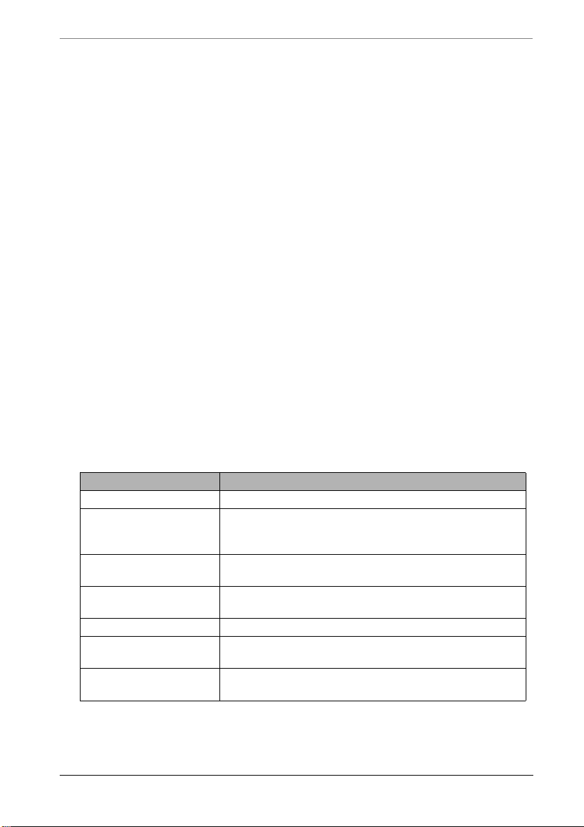
Chapter 5 Troubleshooting
DHCP Troubleshooting
DHCP To The Internet
With DHCP configured for your WAN interface your MultiCom Firewall sends
out discovery packets looking for a DHCP server to give it an IP configuration. If
a DHCP server is not found then the WAN interface is not enabled (i.e. you
cannot reach the Internet.)
Some common connection problems are...
• DHCP is not being used by your Internet Service Provider
• your cabling is incorrect
• your modem is not configured as a bridge
• you changed the time on the MultiCom Firewall but did not reboot
• your WAN and LAN interfaces are using the same IP address range
To check the status of your WAN interface using DHCP visit the WAN DHCP
client status web page using the web server diagnostic pages (found at “Web
Server Status Reports” on page 74.) Also be sure to check the IP configurat ion
received by your workstations and that the firewall IP address received is the IP
address of your MultiCom Firewall (the default setting is 10.0.0.1).
Table 12: WAN DHCP client status states
State of the interface Possible problem
Disabled DHCP is not enabled for this interface.
Expired The existing IP configuration has expired without it
being renewed. Check that firewall was rebooted
after changing the time.
Trying to get address The firewall is in the process of trying to get an IP
configuration from the Internet Service Provider.
Failed The attempt to contact a DHCP server failed, check
all troubleshooting steps.
Assigned The DHCP interface is functioning correctly.
Rebind Normal DHCP activity, check back soon to see if
the state is Assigned or Failed.
Renew Normal DHCP activity, check back soon to see if
the state is Assigned or Failed.
DHCP is not being used by your Internet
98 MultiCom Firewall User’s Manual
Page 99

Your cabling is incorrect
Service Provider
Verify that your Internet Service Provider uses DHCP to configure your
connection to them. Other possible connections may be PPPoE or a static IP
configuration.
State: Trying to get address or State: failed or State: Assigned or State:
Expired
Your cabling is incorrect
Be sure that the WAN interface light on your MultiCom Firewall is green.
If it is not you either have the wrong cable, a faulty cable or the broadband
modem is not plugged in. Try switching cables and verify that the modem is
indeed turned on.
Your modem is not configured as a bridge
Your broadband modem must be configured as a bridge for you to connect
directly to your Internet Service Provider. Verify with the instruction
manual of your modem that it is indeed configured as a bridge. If the two
above steps are not showing a problem this may be your problem.
You changed the time on your firewall but did
not reboot.
The default date of your MultiCom Firewall is January 1970. DHCP works
on a lease system where IP configurations are good for a specified amount
of time. When the original lease runs out your MultiCom Firewall will
attempt to renew its IP configuration information but will erroneously report
that the IP configuration has expired (since the current date is now more
then 30 years in the future.) The easiest fix for this is to reboot the
MultiCom Firewall and it will make a fresh request using the new time.
Your WAN and LAN interfaces are using the
same IP address range
This will normally only happen office to office connections since the default
IP range of 10.0.x.x for your LAN network is never used on the Internet.
Check that the WAN network is not assigning address in the 10.0.x.x range
MultiCom Firewall User’s Manual 99
Page 100

Chapter 5 Troubleshooting
and if it is change either the LAN or the WAN network so that one of them
uses a different range of IP addresses. For example, reconfigure your LAN
address range to be from 192.168.0.2-192.168.0.100.
DHCP On Your Local Network
Using DHCP on to manage your own network’s IP addresses makes
administration convenient. The most common problem is that a device is unable
to receive an IP configuration from the DHCP server (normally your MultiCom
Firewall. Below are some reasons this might happen.
• your workstations are not configured as DHCP clients
• there are not enough IP addresses for your computers
• there is another DHCP server on your network
• there is another device on your network with the same IP address as your
firewall
• you changed the time on the MultiCom Firewall but did not reboot
Be sure to check the LAN DHCP server leases page to see what IP addresses have
been assigned and their status. These require using the web server diagnostic
pages found at “Web Server Status Reports” on page 74.
Your workstations are not configured as
DHCP clients
Check that each workstation is configured as a DHCP client. For some
operating systems setting this configuration requires you to reboot your
workstation. Please refer to the section on Configuring your Computers or
to the manuals that came with your computer for instructions on configuring
this setting.
There are not enough IP addresses for your
computers
The default setting of the MultiCom Firewalls allows for up to 1,000 DHCP
clients. If you either need more than this or have customized your settings
please refer to the Lightning-Linux manual for more information.
There is another DHCP server on your
100 MultiCom Firewall User’s Manual
 Loading...