

Page 1
IOM027FVAE0804
7532 Radar Tank Gauge
Smart transmitter for continuous and non-contact precision
level measurement. For custody transfer and inventory-control
applications with NMI and PTB approval.
Installation and
Operations Manual
www.varec.com
5834 Peachtree Corners East, Norcross (Atlanta), GA 30092 USA
Tel: +1 (770) 447-9202 Fax: +1 (770) 662-8939
Varec, Inc.
Page 2
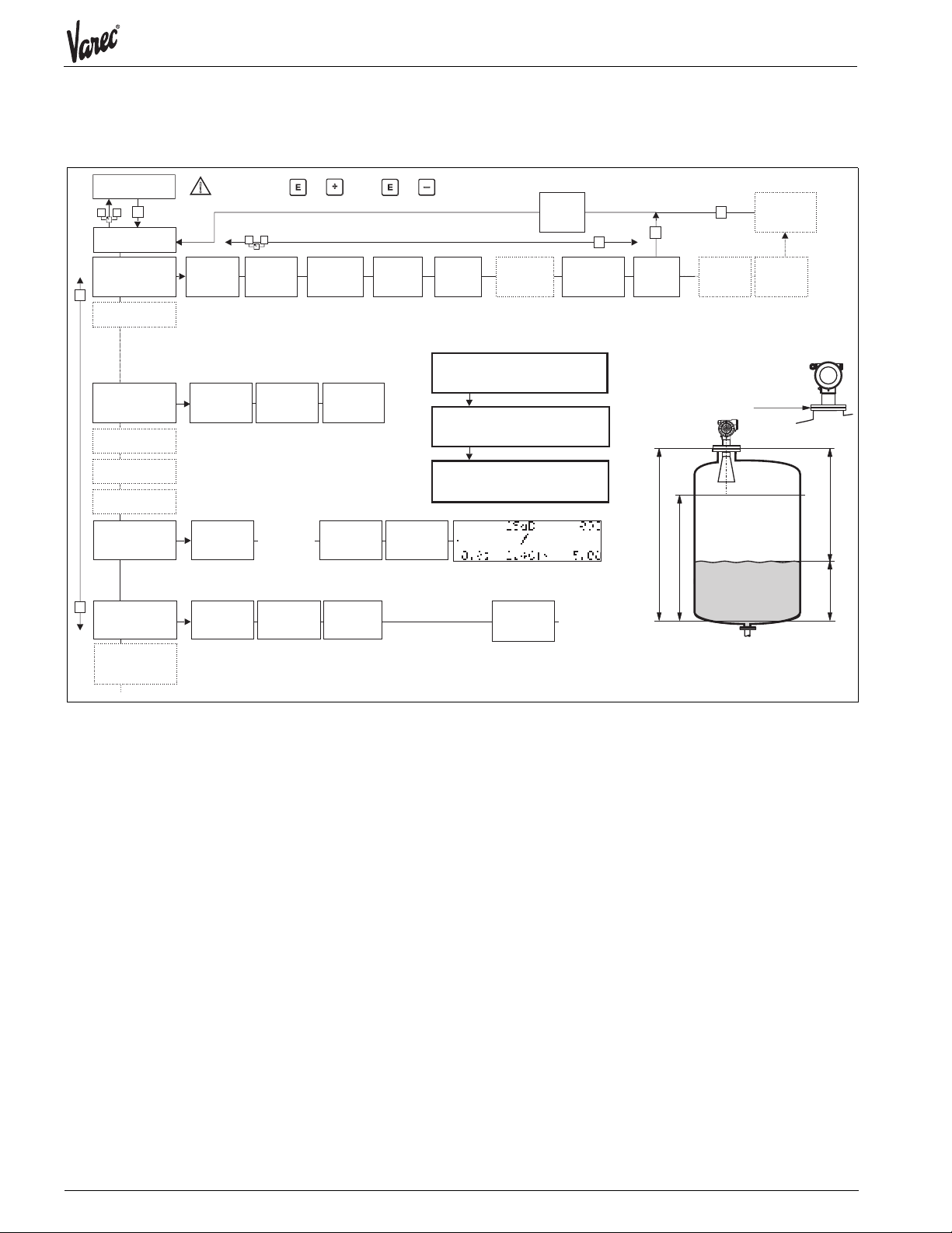
Brief operating instructions
Radar Tank Gauge
000
measured value
+
-
Group
selection
00
basic setup
+
01
safety settings
03
mounting
calibr.
04
linearisation
05
extended calibr.
06
output
09
display
-
0A
diagnostics
0C
system
parameters
Contrast: +or +
E
+
-
002
tank
shape
- flat
ceiling
- stilling
well
…
030
tank
gauging
- dip table
- auto correct.
092
language
0A0
present
error
003
medium
property
- unknown
- <1.9
- 1.9 … 4
- 4 … 10
- >10
033
dip table
mode
… …
0A1
previous
error
004
process
cond.
- standard
- calm
surface
- add. agitator
…
034/035
dip table
09A
plot settings
- envel. curve
- incl. FAC
- incl. cust. map
0A3
reset
555 = History Reset
(333 = reset customer parameters)
005
empty
calibr.
input E
(see sketch)
09B
recording
curve
- single curve
- cyclic
006
full
calibr.
input F
(see sketch)
basic setup
history reset (= 555)
dip table
further points correct linearity
009
history
reset
007
pipe
diameter
only for
bypass +
stilling well
offsetfirst point corrects
0A4
unlock
parameter
= 100: unlocked
100: locked≠
E
008
dist./
meas value
D and L are
displayed
(see sketch)
… …
E
051
check
distance
- ok
- too small
- too big
- unknown
- manual
E
F
E
052
range of
mapping
confirm
suggestion
or specify
range
flange:
referencepoint
of measurement
008
dist./
meas value
053
start
mapping
D
L
Note!
This operating manual explains the installation and initial start-up for the level
transmitter measuring device. All functions that are required for a typical measuring
task are taken into account here.
In addition, the 7532 RTG provides many other functions that are not included in this
operating manual, such as optimizing the measuring point and converting the measured
values.
An overview of all device functions can be found on page 96.
A description of the device functions for the 7532 RTG can also be found on the
enclosed CD-ROM.
2 Installation and Operations Manual
Page 3

Radar Tank Gauge Table of Contents
Table of Contents
1 Safety Instructions ....................................4
1.1 Designated use . . . . . . . . . . . . . . . . . . . . . . . . 4
1.2 Installation, commissioning and operation . . . . 4
1.3 Operational safety . . . . . . . . . . . . . . . . . . . . . . 4
1.4 Return . . . . . . . . . . . . . . . . . . . . . . . . . . . . . . . 5
1.5 Notes on safety conventions and symbols . . . . 6
2 Identification ................................................7
2.1 Device designation . . . . . . . . . . . . . . . . . . . . . . 7
2.2 Scope of delivery . . . . . . . . . . . . . . . . . . . . . . 10
2.3 Certificates and approvals . . . . . . . . . . . . . . . 10
2.4 Registered trademarks . . . . . . . . . . . . . . . . . . 10
3 Mounting ..................................................... 11
3.1 Quick installation guide . . . . . . . . . . . . . . . . . 11
3.2 Incoming acceptance, transport, storage . . . . 12
3.3 Installation Conditions . . . . . . . . . . . . . . . . . . 13
3.4 Installation instructions . . . . . . . . . . . . . . . . . . 17
3.5 Post-installation check . . . . . . . . . . . . . . . . . . 24
4 Wiring ............................................................25
6 Commissioning .........................................45
6.1 Function check . . . . . . . . . . . . . . . . . . . . . . . . 45
6.2 Commissioning . . . . . . . . . . . . . . . . . . . . . . . . 45
6.3 Basic Setup . . . . . . . . . . . . . . . . . . . . . . . . . . . 46
6.4 Basic Setup with the VU 331 . . . . . . . . . . . . . 49
6.5 Mounting calibration with VU 331 . . . . . . . . . . 57
6.6 Basic Setup with the ToF Tool . . . . . . . . . . . . . 66
6.7 Mounting calibration with the ToF Tool . . . . . . 70
7 Maintenance ...............................................73
8 Accessories ................................................75
9 Troubleshooting .......................................77
9.1 Troubleshooting instructions . . . . . . . . . . . . . . 77
9.2 System error messages . . . . . . . . . . . . . . . . . 79
9.3 Application errors . . . . . . . . . . . . . . . . . . . . . . 81
9.4 Spare parts . . . . . . . . . . . . . . . . . . . . . . . . . . . 83
9.5 Return . . . . . . . . . . . . . . . . . . . . . . . . . . . . . . . 86
9.6 Disposal . . . . . . . . . . . . . . . . . . . . . . . . . . . . . 86
9.7 Software history . . . . . . . . . . . . . . . . . . . . . . . 86
4.1 Quick wiring guide . . . . . . . . . . . . . . . . . . . . . 25
4.2 Connecting the measuring unit . . . . . . . . . . . 28
4.3 Equipotential bonding . . . . . . . . . . . . . . . . . . 30
4.4 Degree of protection . . . . . . . . . . . . . . . . . . . 30
4.5 Overvoltage protector . . . . . . . . . . . . . . . . . . 30
4.6 Post-connection check . . . . . . . . . . . . . . . . . . 30
5 Operation .....................................................31
5.1 Quick operation guide . . . . . . . . . . . . . . . . . . 31
5.2 Display and operating elements . . . . . . . . . . . 34
5.3 Local operation . . . . . . . . . . . . . . . . . . . . . . . 37
5.4 Display and acknowledging error messages . 40
5.5 HART communication . . . . . . . . . . . . . . . . . . 41
10 Technical data ...........................................87
10.1 Technical data at a glance . . . . . . . . . . . . . . . 87
11 Appendix .....................................................91
11.1 Operating menu HART (Display modul), ToF Tool
91
11.2 Operating matrix HART / Commuwin II . . . . . . 94
11.3 Description of functions . . . . . . . . . . . . . . . . . . 96
11.4 Function and system design . . . . . . . . . . . . . . 97
Index.......................................................................103
IOM027FVAE0804 3
Page 4

Safety Instructions Radar Tank Gauge
1 Safety Instructions
1.1 Designated use
The Varec Model 7532 Radar Tank Gauge (RTG) is a compact radar level transmitter for
the continuous, contactless measurement of liquids, pastes and sludge in stilling wells.
The device can also be freely mounted outside closed metal vessels because of its
operating frequency of about 6 GHz and a maximum radiated pulsed energy of 1mW
(average power output 1 µW). Operation is completely harmless to humans and animals.
1.2 Installation, commissioning and operation
The 7532 RTG has been designed to operate safely in accordance with current technical,
safety and EU standards. If installed incorrectly or used for applications for which it is
not intended, however, it is possible that application-related dangers may arise, e.g.
product overflow due to incorrect installation or calibration. For this reason, the
instrument must be installed, connected, operated and maintained according to the
instructions in this manual: personnel must be authorised and suitably qualified. The
manual must have been read and understood, and the instructions followed.
Modifications and repairs to the device are permissible only when they are expressly
approved in the manual.
1.3 Operational safety
Hazardous areas
Measuring systems for use in hazardous environments are accompanied by separate “Ex
documentation”, which is an
with the installation instructions and ratings as stated in this supplementary
documentation is mandatory.
• Ensure that all personnel are suitably qualified.
• Observe the specifications in the certificate as well as national and local regulations.
FCC-approval
This device complies with part 15 of the FCC Rules. Operation is subject to the following
two conditions: (1) This device may not cause harmful interference, and (2) this device
must accept any interference received, including interference that may cause undesired
operation.
Caution!
Changes or modifications not expressly approved by the part responsible for
compliance could void the user’s authority to operate the equipment.
integral part
of this Operating Manual. Strict compliance
4 Installation and Operations Manual
Page 5

7532 Safety Instructions
1.4 Return
The following procedures must be carried out before a transmitter is sent to Varec for
repair:
• Always enclose a duly completed “Declaration of contamination” form. Only then can
Varec transport, examine and repair a returned device.
• Enclose special handling instructions if necessary, for example a safety data sheet as
per EN 91/155/EEC.
• Remove all residue which may be present. Pay special attention to the gasket grooves
and crevices where fluid may be present. This is especially important if the fluid is
dangerous to health, e.g. corrosive, poisonous, carcinogenic, radioactive, etc.
Caution!
• No instrument should be sent back for repair without all dangerous material being
completely removed first, e.g. in scratches or diffused through plastic.
• Incomplete cleaning of the instrument may result in waste disposal or cause harm to
personnel (burns, etc.). Any costs arising from this will be charged to the operator of
the instrument.
5
Page 6
Safety Instructions Radar Tank Gauge
1.5 Notes on safety conventions and symbols
In order to highlight safety-relevant or alternative operating procedures in the manual,
the following conventions have been used, each indicated by a corresponding symbol in
the margin.
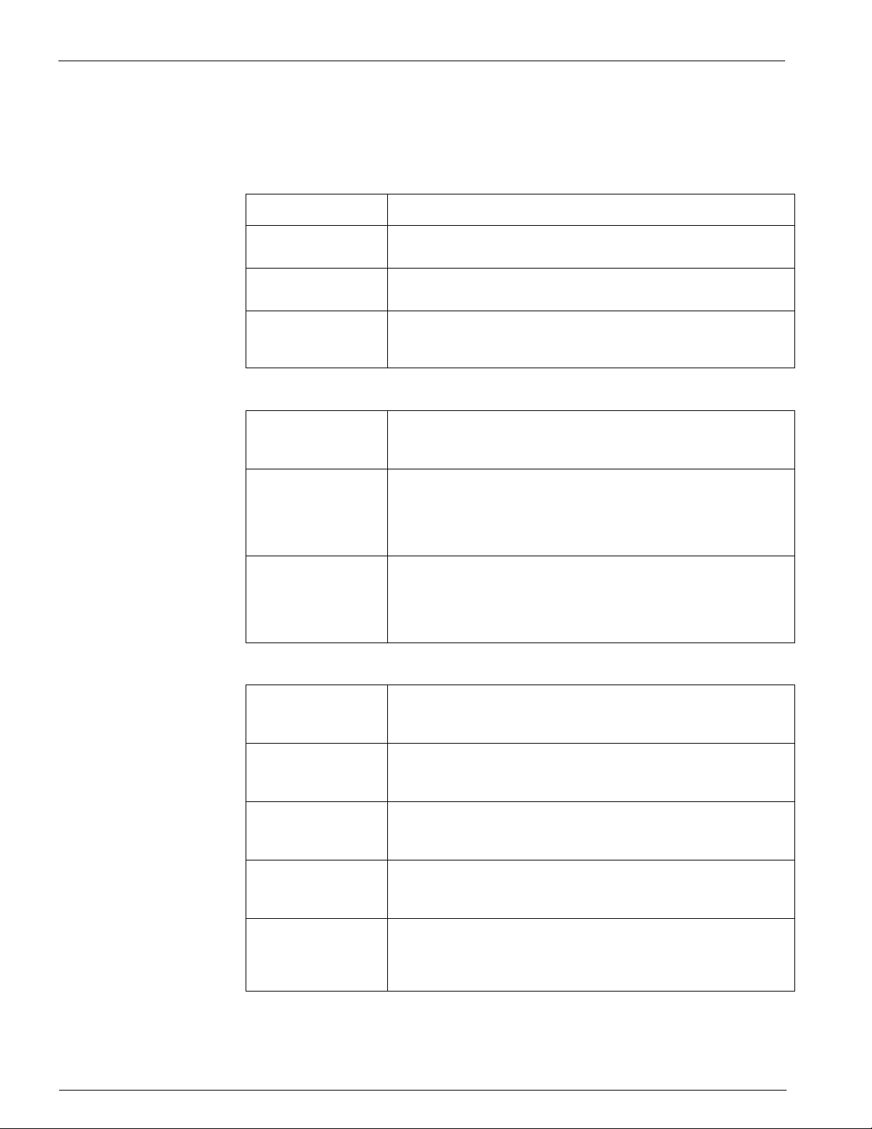
Safety conventions
Symbol Meaning
Explosion protection
Warning!
Caution!
Note!
0
-
.
A warning highlights actions or procedures which, if not performed correctly,
will lead to personal injury, a safety hazard or destruction of the instrument
Caution highlights actions or procedures which, if not performed correctly,
may lead to personal injury or incorrect functioning of the instrument
A note highlights actions or procedures which, if not performed correctly, may
indirectly affect operation or may lead to an instrument response which is not
planned
Device certified for use in explosion hazardous area
If the 7532 RTG has this symbol embossed on its name plate it can be
installed in an explosion hazardous area
Explosion hazardous area
Symbol used in drawings to indicate explosion hazardous areas.
– Devices located in and wiring entering areas with the designation
“explosion hazardous areas” must conform with the stated type of
protection
Safe area (non-explosion hazardous area)
Symbol used in drawings to indicate, if necessary, non-explosion
hazardous areas.
– Devices located in safe areas still require a certificate if their outputs run
into explosion hazardous areas.
Electrical symbols
%
&
)
*
+
Direct voltage
A terminal to which or from which a direct current or voltage may be
applied or supplied
Alternating voltage
A terminal to which or from which an alternating (sine-wave) current
or voltage may be applied or supplied
Grounded terminal
A grounded terminal, which as far as the operator is concerned, is
already grounded by means of an earth grounding system
Protective grounding (earth) terminal
A terminal which must be connected to earth ground prior to making
any other connection to the equipment
Equipotential connection (earth bonding)
A connection made to the plant grounding system which may be of
type e.g. neutral star or equipotential line according to national or
company practice
6 Installation and Operations Manual
Page 7
7532 Identification
2 Identification
2.1 Device designation
2.1.1 Nameplate and Certification Plates
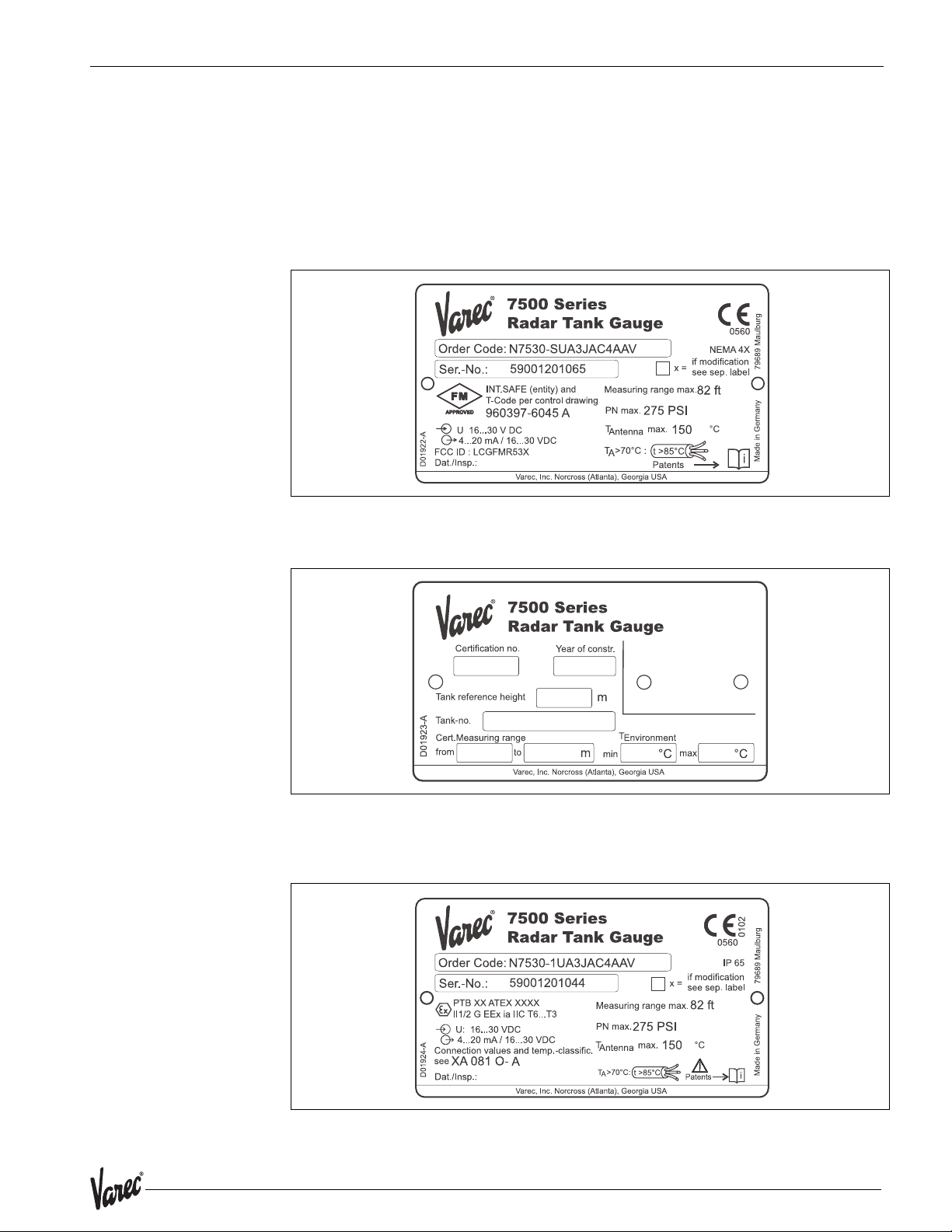
The following technical data are given on the instrument nameplate:
7500RTG_nameplate_label.eps7500RTG_NMI_label.eps
Figure 1: Information on the nameplate of the 7500 RTG (example)
Figure 2: Information on the NMi type plate for custody transfer applications of the
7500 RTG (example)
Figure 3: Information on the PTB type plate for custody transfer applications of the
7500 RTG (example)
7500RTG_ATEX-PTB_label.eps
7
Page 8
Identification Radar Tank Gauge
2.1.2 Ordering structure
Ordering structure 7532 RTG
10 Certificates Basic weight
A For non-hazardous areas 6.5 kg
S FM IS - Class I, Division 1, Group A-D
U CSA IS - Class I, Division 1, Group A-D
1 ATEX II 1/2 G EEx ia IIC T6, note safety instruction (XA) for electrostatic charg-
YSpecial version
20 Antenna type Additional
Type Size Material Sealing
A Planar antenna DN150 / 6" SS316L FKM inside
B Planar antenna DN150 / 6" SS316L HNBR inside
E Planar antenna DN250 / 10" SS316L FKM inside
F Planar antenna DN250 / 10" SS316L HNBR inside 2.1 kg
U Planar antenna DN200 / 8" SS316L FKM inside
V Planar antenna DN200 / 8" SS316L HNBR inside 1.1 kg
W Planar antenna DN300 / 12" SS316L HNBR inside
X Planar antenna DN300 / 12" SS316L FKM inside 2.5 kg
YSpecial version
30 Process connection
AVJ 6"/150 lbs / RF ANSI B16.5 316/316L 11.4 kg
A3J 8"/150 lbs / RF ANSI B16.5 316/316L 19.6 kg
A5J 10"/150 lbs / RF ANSI B16.5 316/316L 28.8 kg
AWJ 6"/300 lbs / RF ANSI B16.5 316/316L 20.9 kg
AXJ 8"/300 lbs / RF ANSI B16.5 316/316L 34.3 kg
A7J 12"/150 lbs / RF ANSI B16.5 316/316L 43.2 kg
CWJ DN150 PN10 / 16 C
CXJ DN200 PN16 C
CZJ DN200 PN25 C
C1J DN150 PN25 C
C6J DN250 PN16 C
C8J DN300 PN16 C
XXJ with flange hub 316L
XVU Varec UNI-Flange 6"/
X3U Varec UNI-Flange 8"/
X5U Varec UNI-Flange 10"/
X7U Varec UNI-Flange 12"/
YY9 Special version
ing!
Flange Dia/Pressure Standard Material
1)
EN 1092,1, B1
EN 1092,1, B1
EN 1092,1, B1
EN 1092,1, B1
EN 1092,1, B1
EN 1092,1, B1
316L 10.6 kg
1)
316L 16.5 kg
1)
316L 22.7 kg
1)
316L 14.7 kg
1)
316L 25.6 kg
1)
316L 36.1 kg
304/1.4301 3.5 kg
DN150/150A,
max. 14.5LBS/PN1/1K,
compatible with:
- 6" 150LBS
- DN150 PN16
- 10K 150A
304/1.4301 5.2 kg
DN200/200A,
max. 14.5LBS/PN1/1K,
compatible with:
- 8" 150LBS
- DN200 PN16
- 10K 200A
304/1.4301 7.5 kg
DN250/250A,
max. 14.5LBS/PN1/1K,
compatible with:
- 10" 150LBS
- DN250 PN16
- 10K 250A
304/1.4301 10.8 kg
DN300/300A,
max. 14.5LBS/PN1/1K,
compatible with:
- 12" 150LBS
- DN300 PN16
- 10K 300A
1) agreeable to DIN2527 Form C
weight
8 Installation and Operations Manual
Page 9
7532 Identification
40 Output and operation
A 4…20 mA HART with VU 331, 4-line alphanumeric dis-
play
YSpecial version
50 Housing
C Aluminium T12-housing with separate connection compartment, coated, IP65
YSpecial version
60 Gland / Entry
2 M20x1.5 cable gland
4 ½ NPT cable entry
9Special version
70 Custody transfer approvals
A NMi, PTB type and test rig approval,
weights&measures approved (< 1 mm)
R Inventory Control Version,
not weights&measures approved (3 mm)
Y Special approval for custody transfer
80 Additional options
A Without additional options
YSpecial version
7532- Complete product designation
9
Page 10

Identification Radar Tank Gauge
2.2 Scope of delivery
Caution!
It is essential to follow the instructions concerning the unpacking, transport and storage
of measuring instruments given in the section “Incoming acceptance, transport, storage”
on page 12.
The scope of delivery consists of:
• Assembled instrument
• ToF Tool (operating program)
• Accessories (Chapter 8)
Accompanying documentation:
• Short manual (basic equalization/troubleshooting): housed in the instrument
• Operating manual (this manual)
• Operating manual: Description of the instrument functions
• Approval documentation: if this is not included in the operating manual.
2.3 Certificates and approvals
CE mark, declaration of conformity
The instrument is designed to meet state-of-the-art safety requirements, has been
tested and left the factory in a condition in which it is safe to operate. The instrument
complies with the applicable standards and regulations in accordance with EN 61010
“Protection Measures for Electrical Equipment for Measurement, Control, Regulation and
Laboratory Procedures”. The instrument described in this manual thus complies with the
statutory requirements of the EG directives. Varec confirms the successful testing of the
instrument by affixing to it the CE mark.
2.4 Registered trademarks
KALREZ ®, VITON ®, TEFLON ®
Registered trademark of the company E.I. Du Pont de Nemours & Co., Wilmington, USA
®
TRI-CLAMP
Registered trademark of the company Ladish & Co., Inc., Kenosha, USA
HART
Registered trademark of HART Communication Foundation, Austin, USA
®
ToF
Registered trademark of the company Endress+Hauser GmbH+Co. KG, Maulburg, Germany
PulseMaster
Registered trademark of the company Endress+Hauser GmbH+Co. KG, Maulburg, Germany
®
®
PhaseMaster
®
Registered trademark of the company Endress+Hauser GmbH+Co. KG, Maulburg, Germany
10 Installation and Operations Manual
Page 11
7532 Mounting
3 Mounting
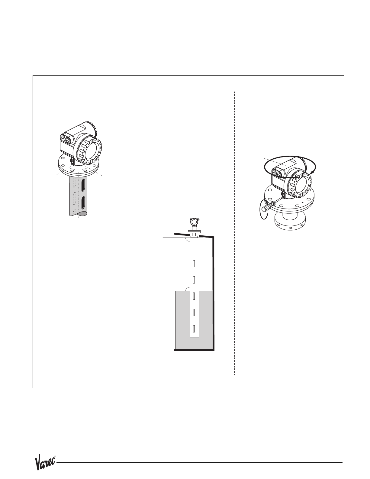
3.1 Quick installation guide
Installation only in stilling well:
Turn housing
The housing can be turned
in order to simplify access to the
display and the terminal compartment
T12 housing
2
90˚
The performance of the 7532 RTG
planar antenna is not dependent on the
alignment or geometry of standard stilling
wells.
No special alignment is required.
However, make sure that the planar
antenna is installed vertically relative
to the stilling well axis.
3
1
Allen key
.
.
4 mm
tighten strongly
by hand
Note!
The 7532 RTG with planar antenna is designed for use on stilling-wells only!
L00-FMR532xx-17-00-00-en-002
11
Page 12

Mounting Radar Tank Gauge
3.2 Incoming acceptance, transport, storage
3.2.1 Incoming acceptance
Check the packing and contents for any signs of damage.
Check the shipment, make sure nothing is missing and that the scope of supply matches
your order.
3.2.2 Transport
Caution!
Follow the safety instructions and transport conditions for instruments of more than
18 kg. Do not lift the measuring instrument by its housing in order to transport it.
3.2.3 Storage
Pack the measuring instrument so that is protected against impacts for storage and
transport. The original packing material provides the optimum protection for this.
The permissible storage temperature is -40 °C…+80 °C.
12 Installation and Operations Manual
Page 13
7532 Mounting
inactive length
3.3 Installation Conditions
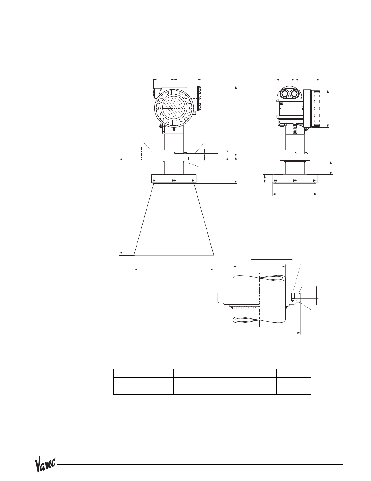
3.3.1 Dimensions
L
DIN, ANSI,
JIS
68 (2.68") 94 (3.7")
E+H UNI flange
(max. 1 bar)
DN200…300 / 8…12”
version with
antenna widening
Ø D
detail A:
flange adapter
(see under)
238 (9.37")
8 (0.31")
93 (3.66")
30
(1.18")
version without widening
detail A
flange hub for the connection
to flanges provided by the customer
Ø 78 (3.07")
Ø 62,5 (2.46")
65 (2.56")
ENDRESS+HAUSER
Micropilot II
Ø 150 (5.91")
DN150 / 6”
85 (3.35")
mounting:
4 bolts M6 / 90°
e.g.DIN 912
O-Ring 85.3 x 3.53,
included
(same material as
sensor seal)
Ø 129 (5.08")
60
(2.36")
9
(0.35")
flange hub
Ø 99,5 (3.92")
Figure 4: Dimensions 7532 RTG
Antenna version DN150 / 6" DN200 / 8" DN250 / 10" DN300 / 12"
L [mm] 93 337 490 517
Ø D [mm] no horn 190 240 290
Note!
The inactive length of 60 mm prevents condensation effects to the antenna performance. Special versions with longer construction are available.
L00-FMR532xx-06-00-00-en-001
13
Page 14
Mounting Radar Tank Gauge
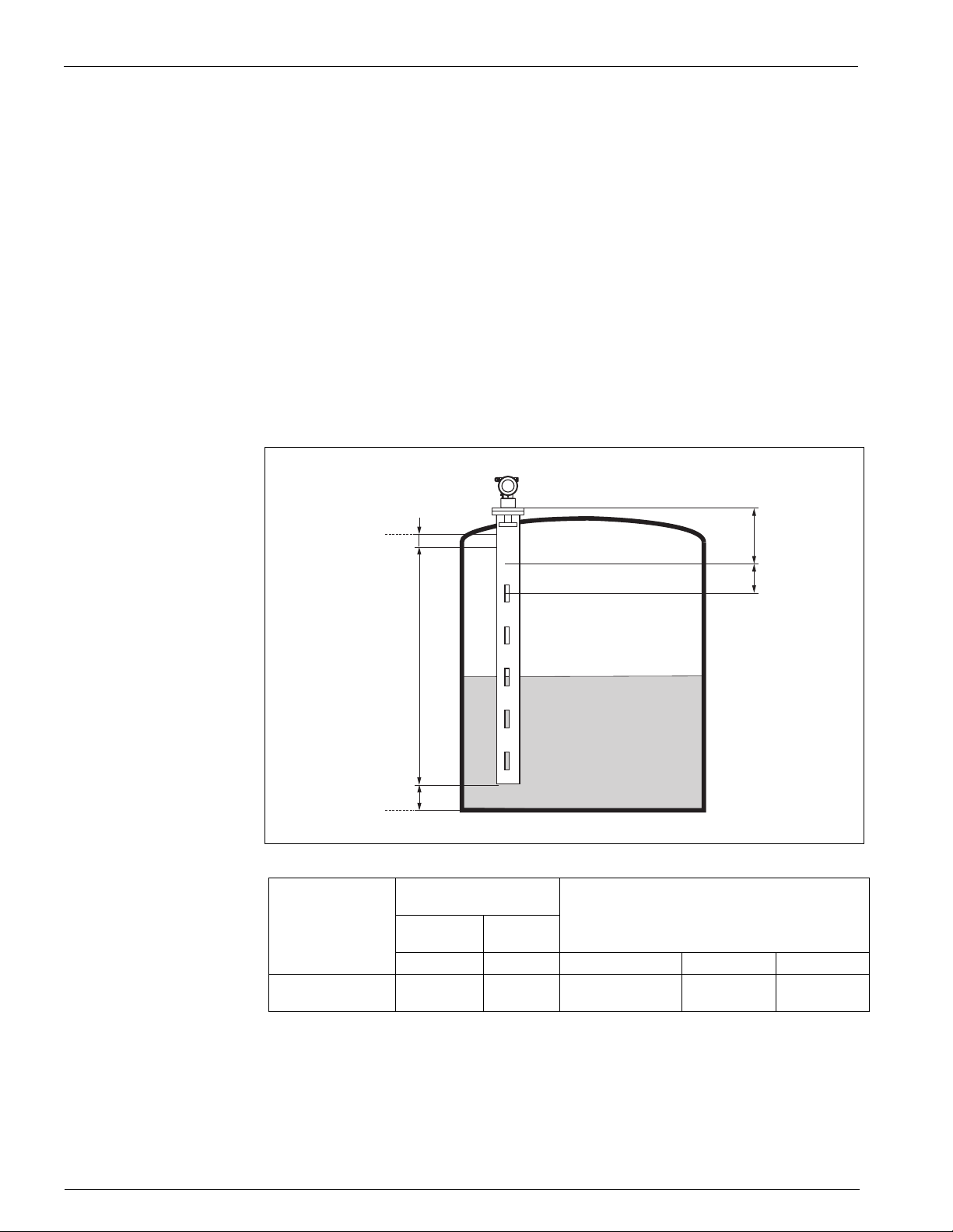
3.3.2 Engineering tips
Measuring conditions
• The measuring range starts at the bottom end of the stilling well.
• In case of media with a low dielectric constant (groups A and B), the pipe end can be
visible through the medium at low levels. In order to guarantee the required accuracy
in these cases, it is recommended to position the zero-point at a distance C above the
tank bottom (see Fig.).
• In applications with planar or parabolic antennas, especially for media with low
dielectric constants (see page 15), the end of the measuring range should not be closer
than 1 m (40”) to the flange.
•For overspill protection, it is possible to define a safety distance (SD) additionally to
the blocking distance (BD).
• This safety distance (SD) is set to 0.5 m (20") by default and generating an alarm in
case the level rises inside the safety distance.
• Distance B defined the smallest recommended measurement range.
• Depending on its consistence, foam can either absorb microwaves or reflect them off
the foam surface. Measurement is possible under certain conditions.
100%
7532 RTG (planar) 1 / 3.28 0.5 / 1.6 1000 / 40 0.5 / 1.64
A
max. level
B
C
0%
reference: flange / BD
(see picture)
Blocking
distance
BD [m / ft] SD [m / ft] A [mm / inch] B [m / ft] C [mm / inch]
Safety
distance
reference: antenna tip
(see picture)
recommended additional settings
BD
SD
L00-FMR53xxx-17-00-00-en-008
150…300 /
6…12
Behaviour if measuring range is exceeded
The behaviour in case of the measuring range being exceeded can be freely set: the
default setting is a current of 22 mA and the generation of a digital warning (E681).
14 Installation and Operations Manual
Page 15
7532 Mounting
Measuring range
The usable measuring range depends on the size of the antenna, the reflectivity of the
medium, the mounting location, and eventual interference reflections.
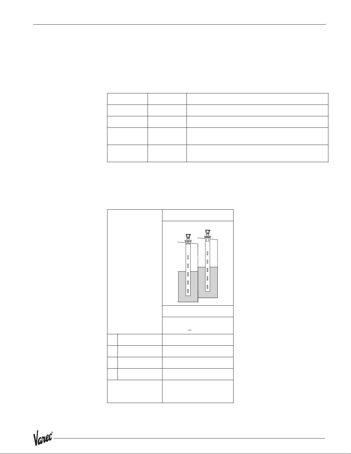
The following tables describe the groups of media as well as the achievable measuring
range as a function of application and media group. If the dielectric constant of a
medium is unknown, it is recommended to assume media group B to ensure a reliable
measurement.
Product class DK (εr) Examples
A 1.4 … 1.9 non-conducting liquids, e.g. liquefied gas
B 1.9 … 4 non-conducting liquids, e.g. benzene, oil, toluene, …
C 4 … 10 e.g. concentrated acids, organic solvents, esters, aniline,
alcohol, acetone, …
D > 10 conducting liquids, e.g. aqueous solutions, dilute acids and
alkalis
1)Treat Ammonia NH3 as a medium of group A, e.g. always use a stilling well.
1)
Measuring range depending on product class for 7532 RTG:
Product class Stilling well/ Bypass
Measuring range
7532 RTG
DN150
>
A DK(
B DK(
εr)=1,4…1,9 38 m/124 ft
εr)=1,9…4 38 m/124 ft
C DK(
D DK(
max. measuring
range with custody
transfer approvals
εr)=4…10 38 m/124 ft
εr)>10 38 m/124 ft
20 m/65 ft
15
Page 16
Mounting Radar Tank Gauge
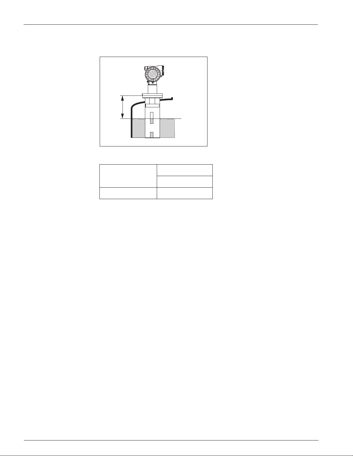
Blocking distance
The blocking distance (= BD) is the minimum distance from the reference point of the
measurement (mounting flange) to the medium surface at maximum level.
referencepointof
measurement
BD
20mA
Max.
Level
100%
L00-FMR53xxx-15-00-00-en-003
Blocking distance
Stilling well / Bypass
(BD)
7532 RTG
from Flange 1 m/40"
Note!
Inside the blocking distance a reliable measurement can not be guaranteed.
16 Installation and Operations Manual
Page 17
7532 Mounting
3.4 Installation instructions
3.4.1 Mounting kit
In addition to the tool needed for flange mounting, you will require the following tool:
• 4 mm Allen wrench for turning the housing.
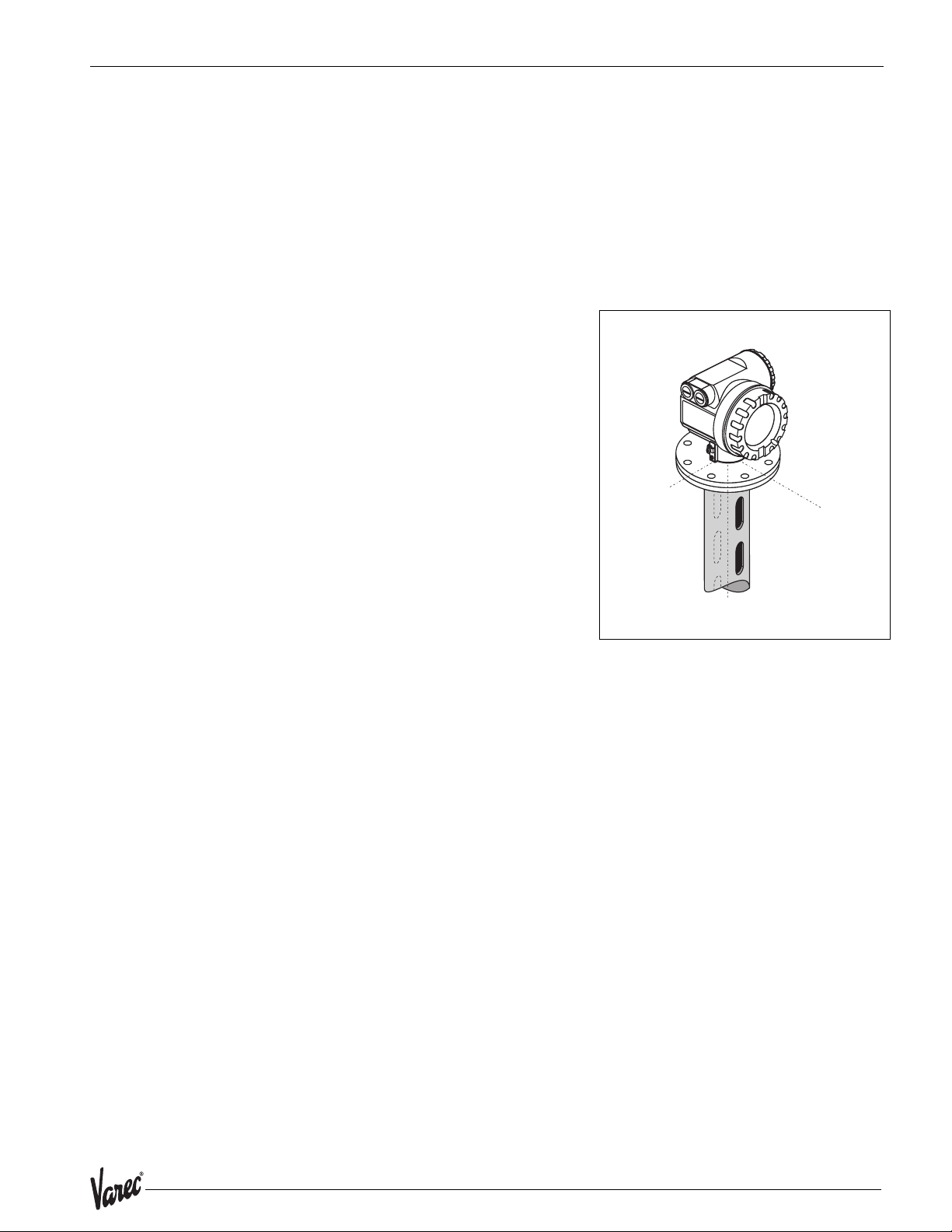
3.4.2 Installation in stilling well
Optimum mounting position for 7532 RTG
Standard installation
When mounting in the stilling well, please
observe engineering tips on page 14 and
the following points:
• After mounting, the housing can be
turned 350° in order to simplify access to
the display and the terminal
compartment.
• planar axis vertical to flange.
• Measurements can be performed
through an open ball valve without any
problems.
Recommendations for the stilling well
• Metal (no enamel coating, plastic on request).
•Constant diameter.
• Weld seam as smooth as possible and on the same axis as the slots.
• Slots offset 180° (not 90°).
• Slot width respectively diameter of holes max. 1/10 of pipe diameter, de-burred.
Length and number do not have any influence on the measurement.
• Select antenna extension as big as possible. For intermediate sizes (e.g. 180 mm)
select next larger antenna extension and adapt it mechanically. Maximum gap allowed
between the antenna/horn of 7532 RTG and the inside of the stilling well is 5 mm (3/
16").
• The antennna extension of the 7532 RTG is mounted with defined pressure.
It is strongly recommended not to dismantle this antenna.
• Dimensions of a nozzle for manual gauging must be adapted to the dimensions of
the horn antenna used, compare to page page 23.
Stilling wells with pipe expansion
• When using a 7532 RTG, a gradual pipe expansion from DN150 to DN200 / DN200
to DN250 / DN250 to DN300 is acceptable. In such cases, the top end of the piping
must have a minimum length of 0.5 m in front of the expansion (see table on page 18).
Ideally, a dip socket is used for this.
• Greater expansion of the piping (e.g. DN150 to DN300) is possible if the top end of
the pipe is extended accordingly (see table on page 18).
• Avoid pipe expansions at right angles.
L00-FMR532xx-17-00-00- en-003
17
Page 18
Mounting Radar Tank Gauge
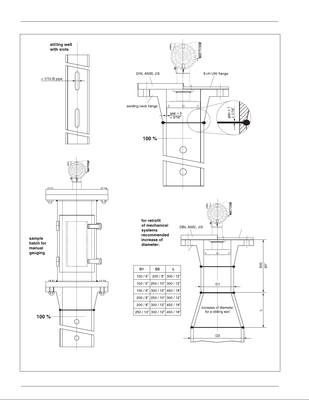
Examples for the construction of stilling wells
7532 RTG
7532 RTG
18 Installation and Operations Manual
L00-FMR532xx-17-00-00-en-004
Page 19
7532 Mounting
3.4.3 Turn housing
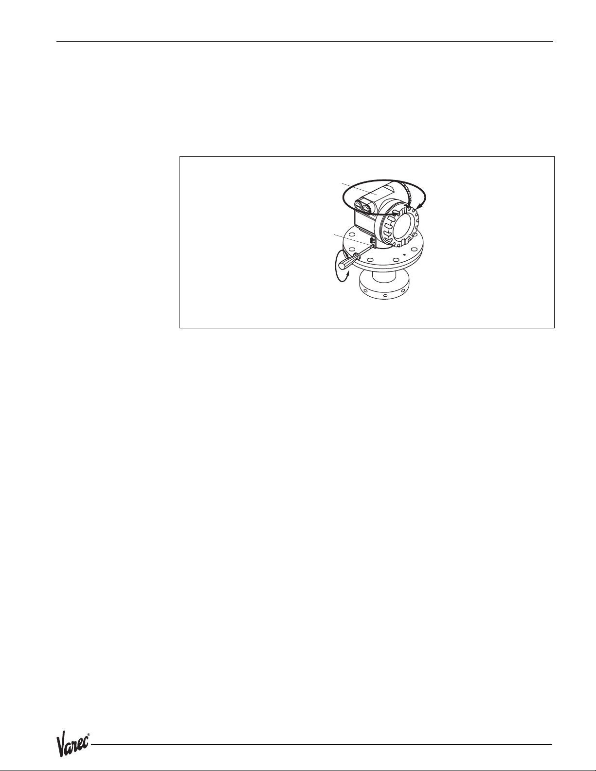
After mounting, the housing can be turned 350° in order to simplify access to the display
and the terminal compartment. Proceed as follows to turn the housing to the required
position:
• Undo the fixing screws (1)
• Turn the housing (2) in the required direction
• Tighten up the fixing screws (1)
T12 housing
2
1
Allen key
4 mm
tighten strongly
by hand
L00-FMR532xx-17-00-00- en-005
19
Page 20
Mounting Radar Tank Gauge
3.4.4 Installation with Varec UNI flange
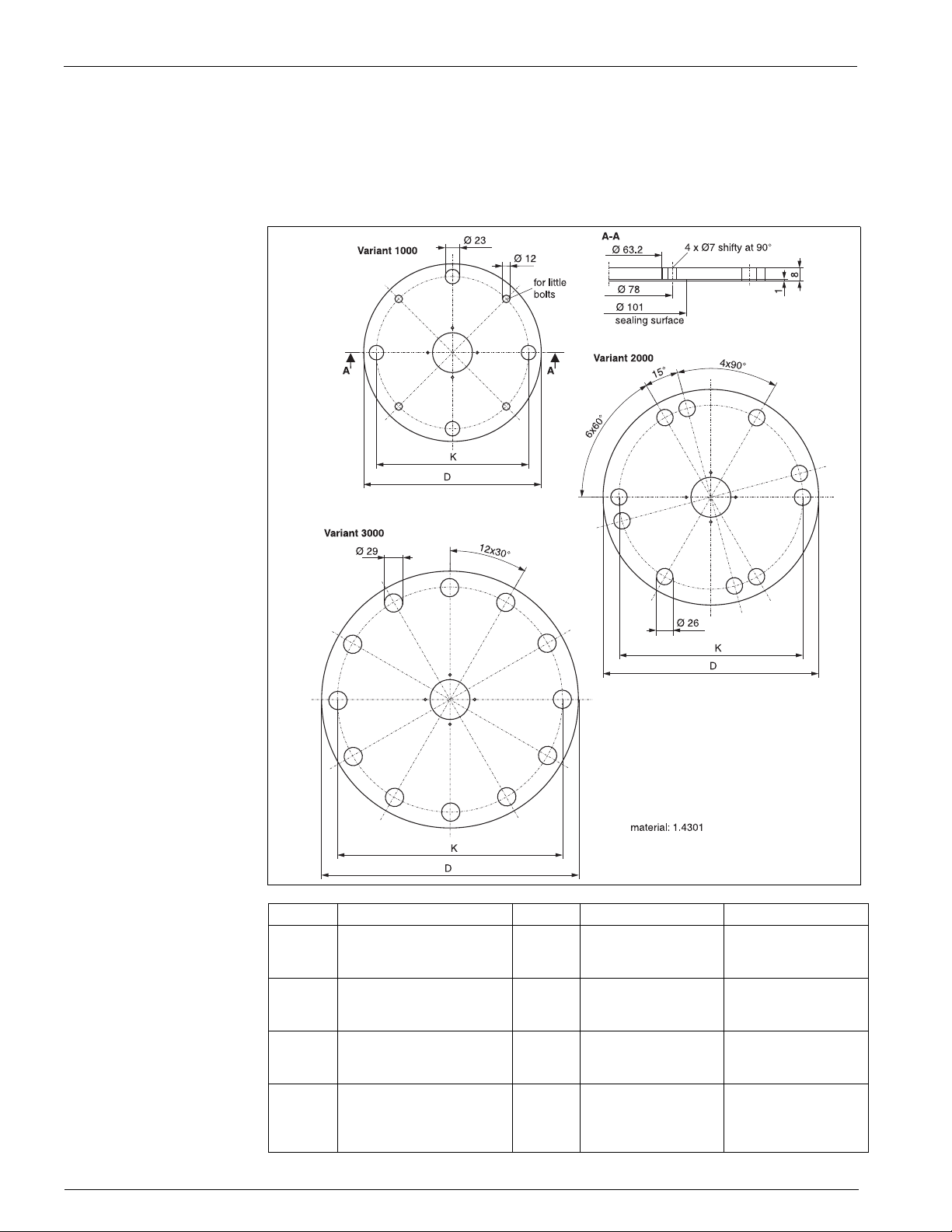
Installation tips
Varec UNI flanges are designed for non-pressurized operation respectively max. 1 bar
absolute pressure. The number of bolts has sometimes been reduced. The bolt-holes
have been enlarged for adaption of dimensions, therefore, the flange needs to be
properly aligned to the counterflange before the bolts are tightened.
Version Compatible with D [mm] K [mm] Type plate no.
1000 DN150 PN16
ANSI 6" 150lbs
JIS 10K 150
2000 DN200 PN16
ANSI 8" 150lbs
JIS 10K 200
3000 DN250 PN16
ANSI 10" 150lbs
JIS 10K 250
4000 DN300 PN16
ANSI 12" 150lbs
JIS 10K 300
280 240 942455-3001
340 294.5 942455-3002
405 358 942455-3003
482 410 (for DIN), 431,8
(for ANSI), 400 (for
JIS),
404,5 (for DIN + JIS)
942455-3004
20 Installation and Operations Manual
L00-FMR53xxx-06-00-00-en-001
Page 21
7532 Mounting
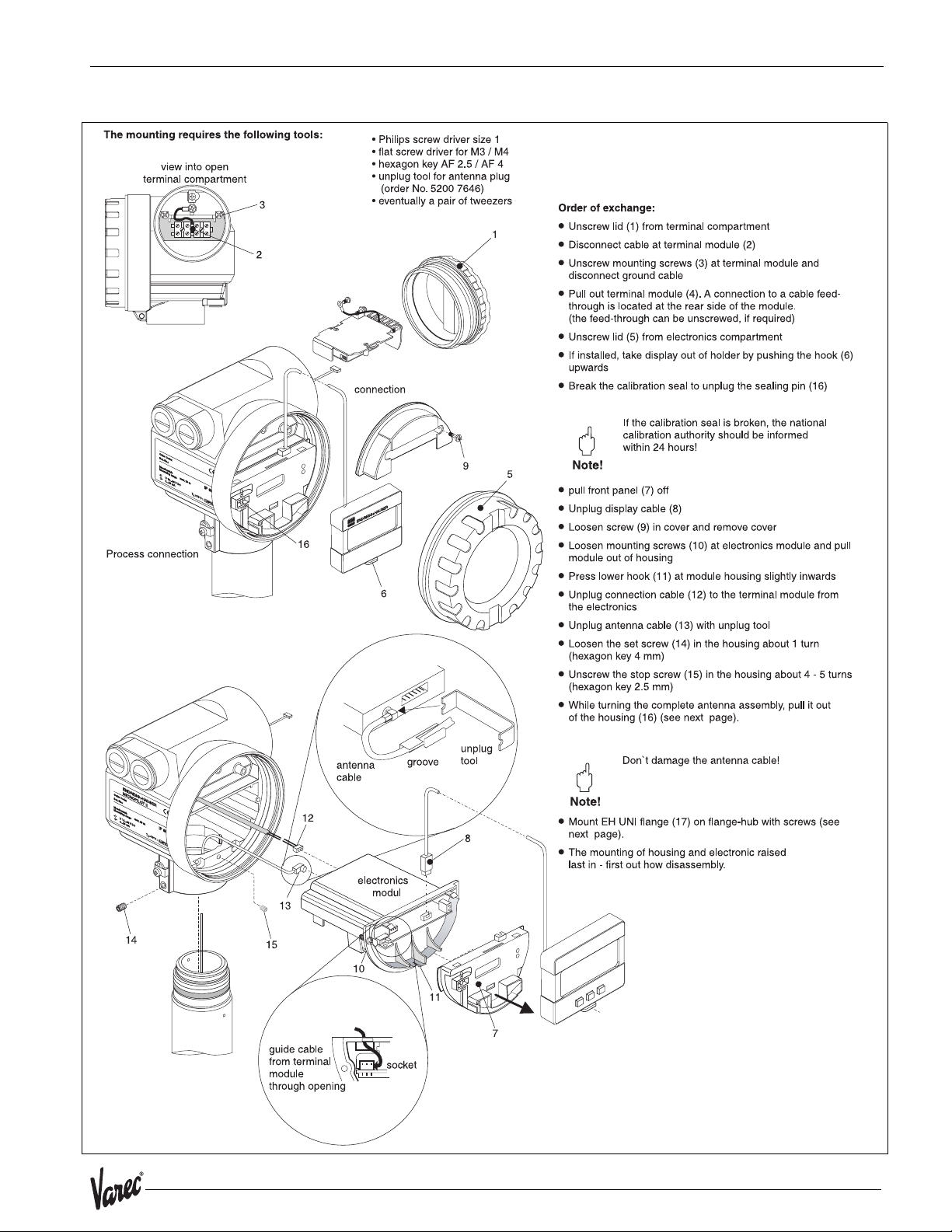
Preparation for the installation of the Varec UNI flange
21
532xx-00-00-06-en-002
Page 22
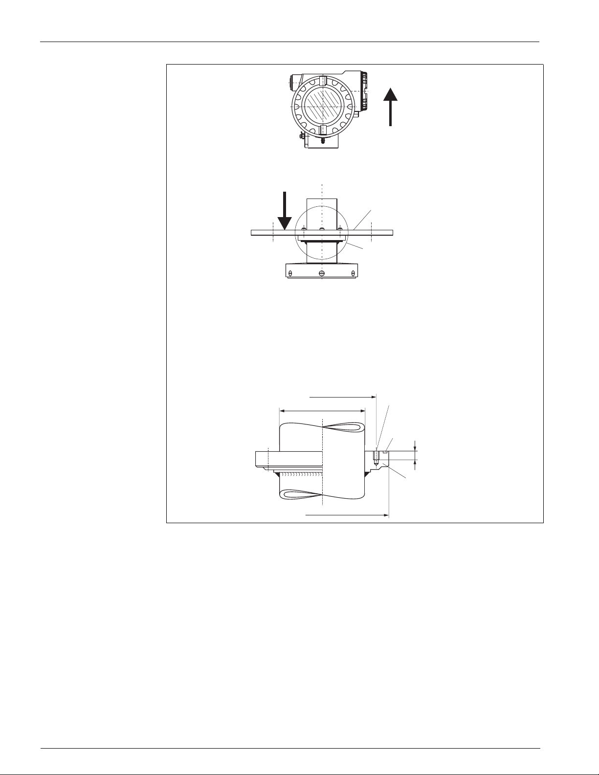
Mounting Radar Tank Gauge
pull off housing
16
mount Varec UNI flange
17
Varec UNI flange
(max. 1 bar)
detail A:
flange adapter
(see under)
detail A
flange hub for the connection
to flanges provided by the customer
mounting:
Ø 78
Ø 62.5
Ø 99.5
4 bolts M6 / 90˚
e.g. DIN 912
O-Ring 85.3 x 3.53,
included
(same material as
sensor seal)
9
flange hub
L00-FMR532xx-00-00-06 -en-003
22 Installation and Operations Manual
Page 23
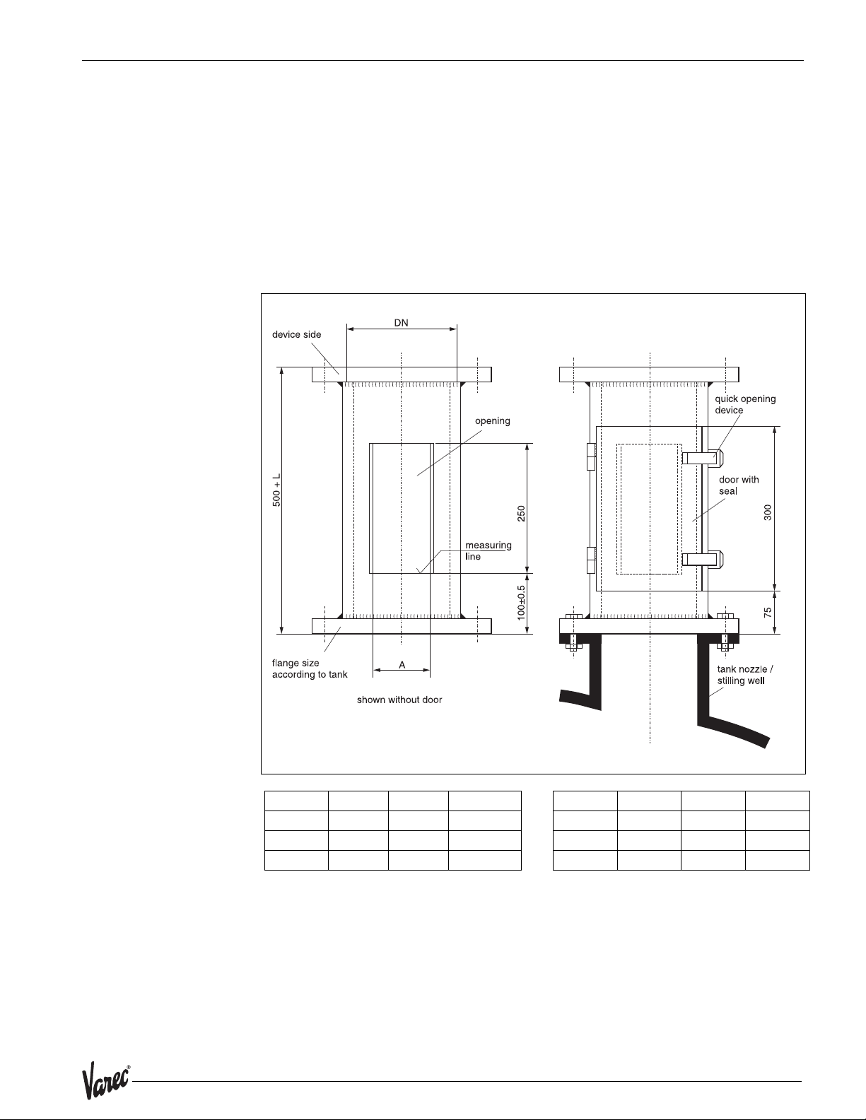
7532 Mounting
3.4.5 Mounting with Sample hatch on stilling well
Installation tips
For control and cleaning purposes as well as for hand dipping (tape), a sample hatch
gauging is recommended. The sensor head can be easily checked in the area of the
opening. Manual gauging with gauge rod or tape is possible without removal of the
transmitter. The lower edge of the opening is the reference for the gauging. The
construction is only suitable for non-pressurized operation.
Note!
The nozzle for manual gauging is not part of the standard offering from Varec. Please
contact Varec for further information.
Flange DN150 DN200 DN250/300 Flange ANSI 6" ANSI 8" ANSI 10"
PN [lbs]
2)Only dimensions adapted to standard. Designed for non-pressurized operation only,
2)
16 16 16 PN [lbs]
A [mm] 110 140 170 A [mm] 110 140 170
L [mm} — 300 450 L [mm] — 300 450
therefore thickness of flange can be reduced (e.g. 8mm).
2)
150 150 150
L00-FMR53xxx-06-00-00-en-004
23
Page 24
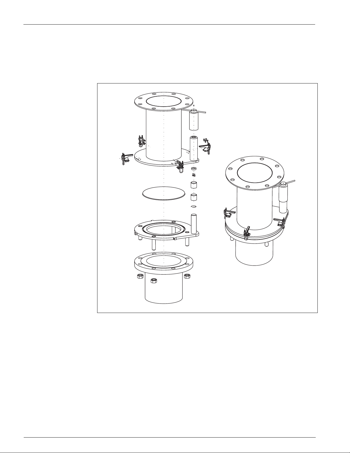
Mounting Radar Tank Gauge
3.4.6 Mounting with Pivoting element
Installation tips
The Pivoting element serves to swivel the 7500 RTG from the measuring position, e.g.
to clean the antenna or dip the tank.
The pivoting element is not part of the standard offering from Varec, special offers
available under ref. number MVTFM0422.
3.5 Post-installation check
After the measuring instrument has been installed, perform the following checks:
• Is the measuring instrument damaged (visual check)?
• Does the measuring instrument correspond to the measuring point specifications
such as process temperature/pressure, ambient temperature, measuring range, etc.?
• Is the flange marking correctly aligned? (see page 11)
• Have the flange screws been tightened up with the respective tightening torque?
• Are the measuring point number and labeling correct (visual check)?
• Is the measuring instrument adequately protected against rain and direct sunlight
(see page 75)?
24 Installation and Operations Manual
L00-FMR53xxx-17-00-00-en-013
Page 25

7532 Wiring
4 Wiring
4.1 Quick wiring guide
When grounding conductive screens, the corresponding directives EN 60079-14 and EN
1127-1 must be observed. Recommendation for safe grounding of conductive screens:
Wiring
25
Page 26
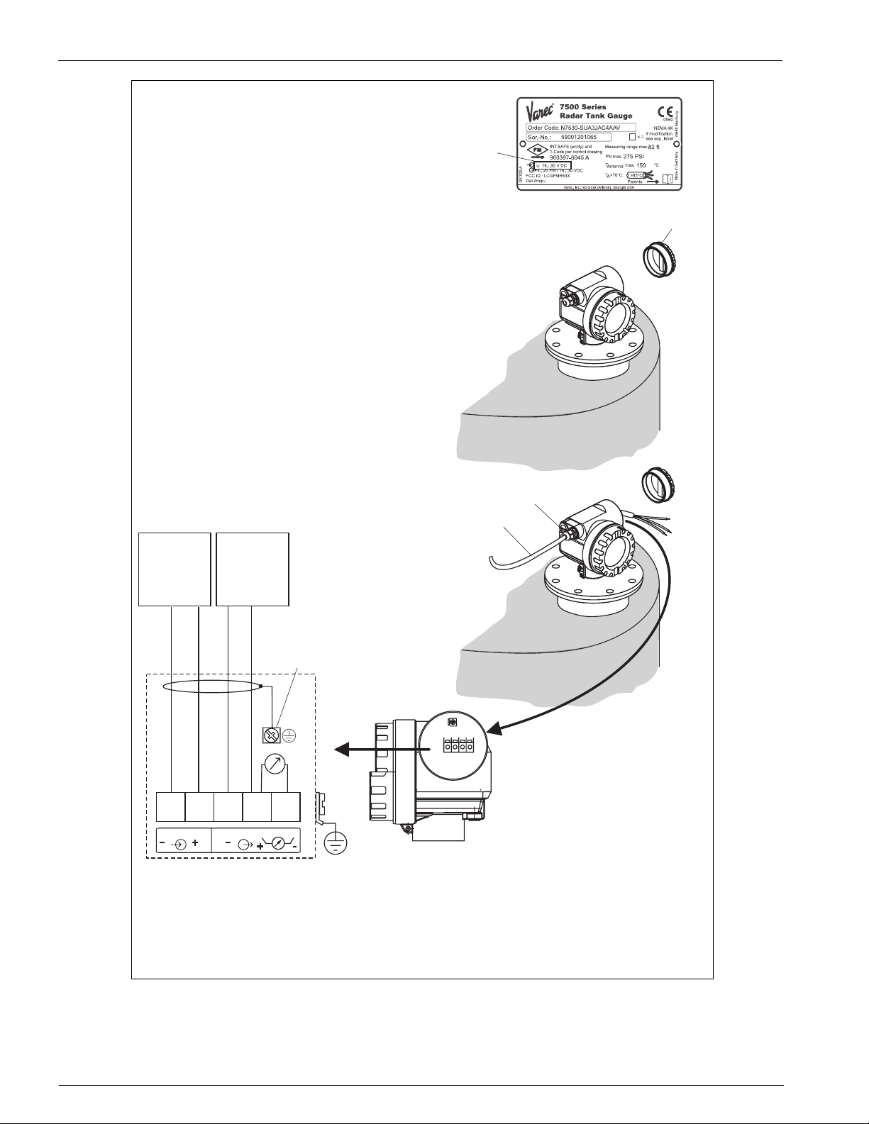
Wiring Radar Tank Gauge
Before connection please note the following:
"
●
Caution!
When you use the measuring system in hazardous areas, make sure you comply with
national standards and the specifications in the safety instructions (XA’s).
Make sure you use the specified cable gland.
-
The power supply must be identical to the data on the
nameplate (1).
●
Switch off power supply before connecting up the device.
●
Connect Equipotential bonding to transmitter ground terminal
before connecting up the device.
●
Tighten the locking screw:
It forms the connection between the antenna and the housing
ground potential.
Connect up the 7500 RTG as follows:
Before unscrew housing cover (2) at seperate connection room
turn off the power supply!
●
Insert cable through gland (3).
Use screened, twisted wire pair.
1
2
-
power:
24 VDC
(16…30 V)
Only ground screening of the line (5) on sensor side.
●
Make connection (see pin assignment).
●
Tighten cable gland (4).
●
Screw off housing cover (2).
●
Switch on power supply.
signal:
24 VDC
12345
1
2
3
4
4
3
5
1234
plant
ground
5
A 7500 RTG situated in a hazardous area is connected as a single
device
to a power supply unit and transmitter situated outside of
the hazardous area. In this case, it is recommended that the screen
be connected directly to the 7500 RTG at the housing's earth,
whereby the 7500 RTG and the power supply unit are connected to
the same potential matching line (PML).
75xx_wiring.eps
26 Installation and Operations Manual
Page 27
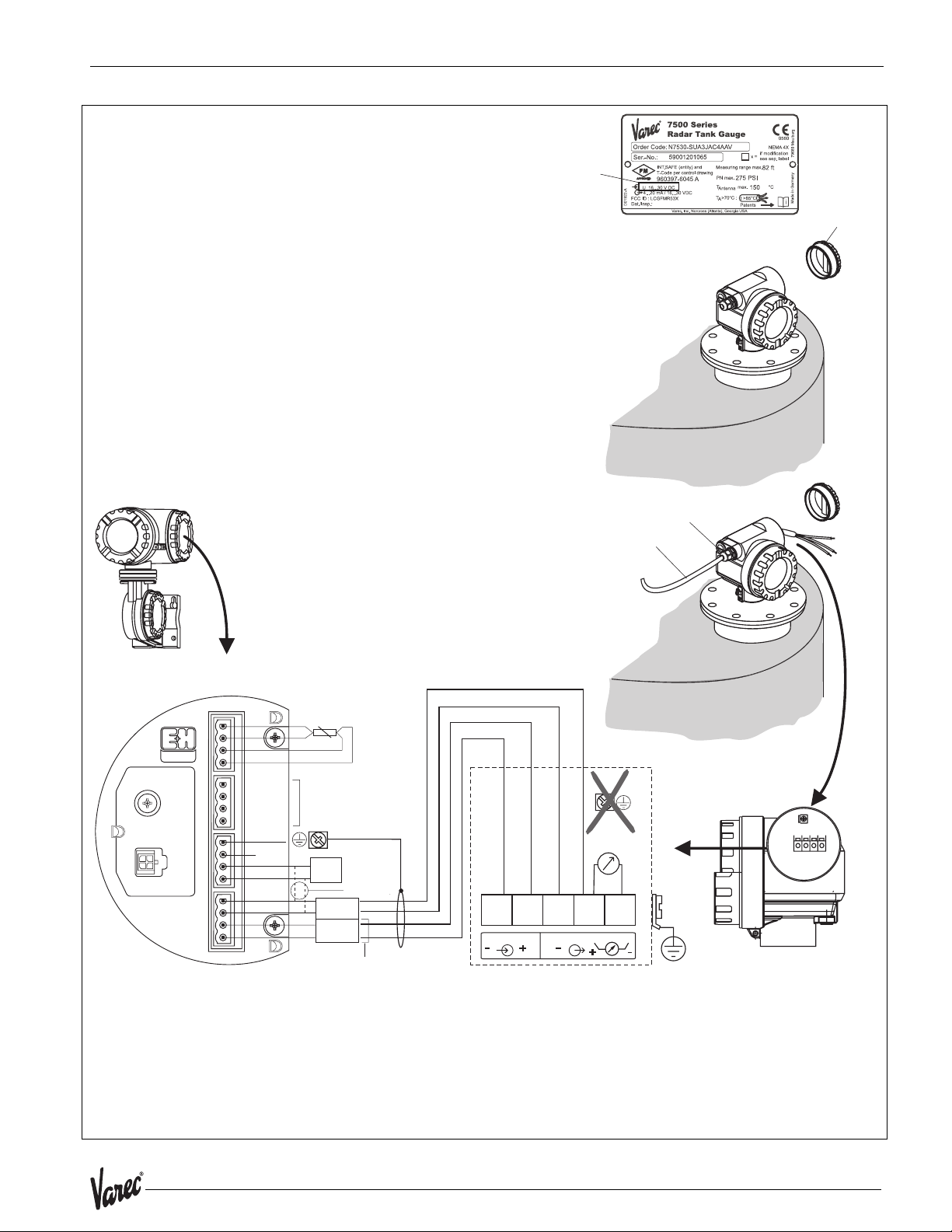
7532 Wiring
Wiring with Tank Side Monitor 4590
Before connection please note the following:
"
●
Caution!
When you use the measuring system in hazardous areas, make sure you comply with
national standards and the specifications in the safety instructions (XA’s).
Make sure you use the specified cable gland.
-
Tank Side Monitor
4590 TSM
The power supply must be identical to the data on the
nameplate (1).
●
Switch off power supply before connecting up the device.
●
Connect Equipotential bonding to transmitter ground terminal
before connecting up the device.
●
Tighten the locking screw:
It forms the connection between the antenna and the housing
ground potential.
Connect up the 7500 RTG as follows:
Before unscrew housing cover (2) at seperate connection room
turn off the power supply!
●
Insert cable through gland (3).
Use screened, twisted wire pair.
●
Make connection (see pin assignment).
●
Tighten cable gland (4).
●
Screw off housing cover (2).
●
Switch on power supply.
1
2
4
3
NRF 590 i.s. terminal board
intrinsicaly safe
terminal board
D+
16
S+
17
S-
18
D-
19
20
21
22
23
24
25
26
27
28
29
30
31
OPT1
OPT2
OPT3
OPT4
+
H
+
H
-
+
H
+
P
-
RTD
grounding single sided
i.s. module wiring
on Tank Side Monitor
4590 TSM
Internally
HART
interconnected
sensor
as one HART
fieldbus loop
+
4
-
3
+
2
-
1
For Micropilot
only for
S-series only!
7500 RTG
grounding not on
7500 RTG
1234
plant
12345
1
2
3
4
ground
5
The 7500 RTG is - possibly in combination with other devices - connected to a Tank
Side Monitor in a hazardous area. In this case, it is recommended that you ground
the cable screen centrally at the Tank Side Monitor and connect all devices to the
same potential matching line (PML). If, for functional reasons, a capacitive coupling is
required between local earth and screen (multiple grounding), ceramic condensers
with a dielectric strength of min. 1500 V
eff must be used, whereby the total capacitance
of 10 nF must not be exceeded. Notes on grounding interconnected intrinsically safe
devices are provided by the FISCO model
75xx_wiring_w_TSM.
27
Page 28
Wiring Radar Tank Gauge
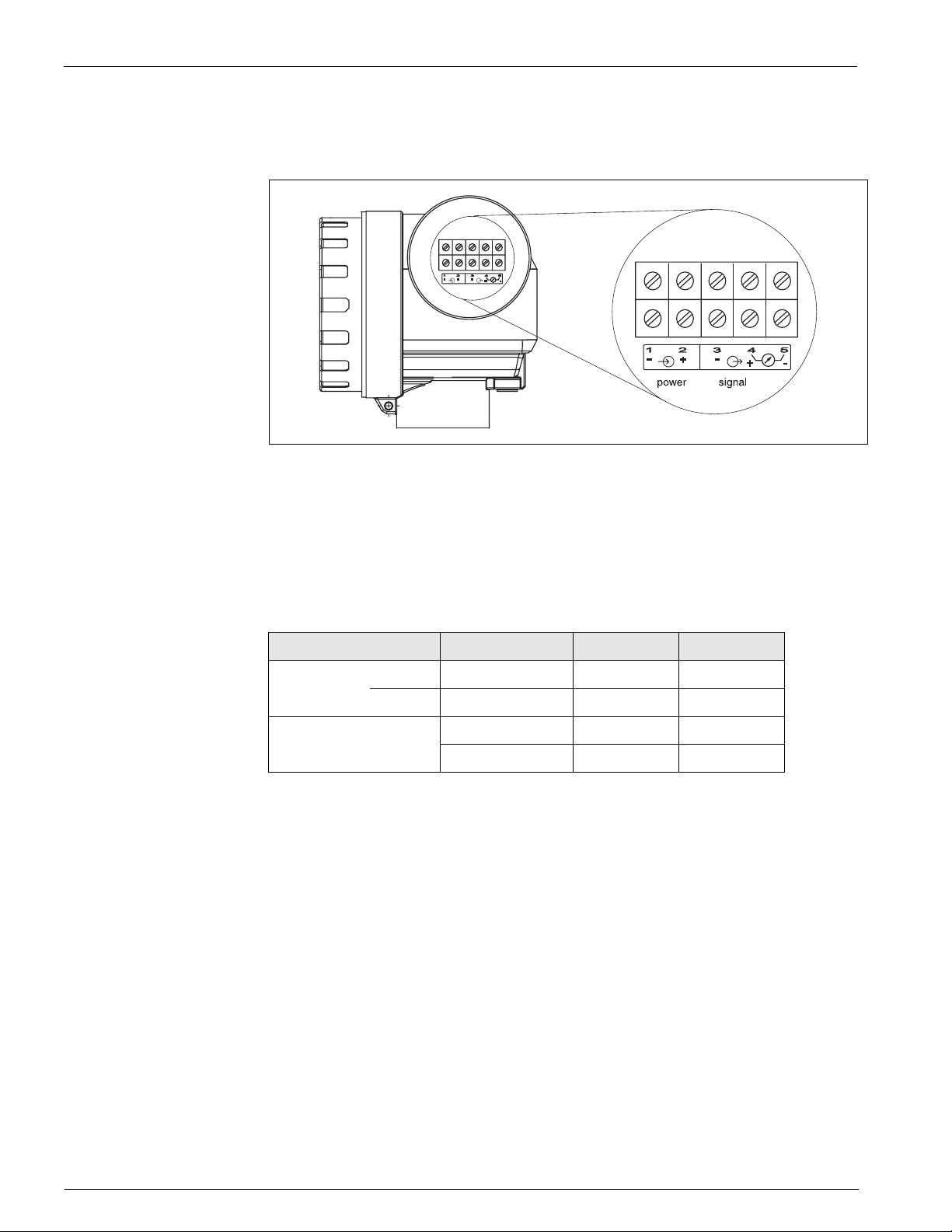
4.2 Connecting the measuring unit
Terminal compartment
The housing comes with a separate terminal compartment.
Load HART
Minimum load for Hart communication: 250 Ω
L00-FMR53xxx-04-00-00-en-001
Cable entry
Cable gland: M20x1.5 or Pg13.5
Cable entry: G ½ or ½ NPT
Supply voltage
Direct current voltage: 16…36 VDC
.
Communication Terminal voltage minimal maximal
Power supply Standard U
Ex U (20 mA) = 16 V 30 V
Signal
Ex
(20 mA) = 16 V 36 V
U (4 mA) = 11,5 V 30 V
U (20 mA) = 11,5 V 30 V
Power consumption
Max. 330 mW at 16 V, max. 500 mW at 24 V, max. 600 mW at 30 V.
Current consumption
Max. 21 mA (50 mA inrush current).
Power supply
For stand alone operation recommended via e.g. Varec RN 221N.
mm accuracy
For measurements with mm accuracy the measured variable must be transmitted
using HART protocol to ensure the necessary resolution.
28 Installation and Operations Manual
Page 29
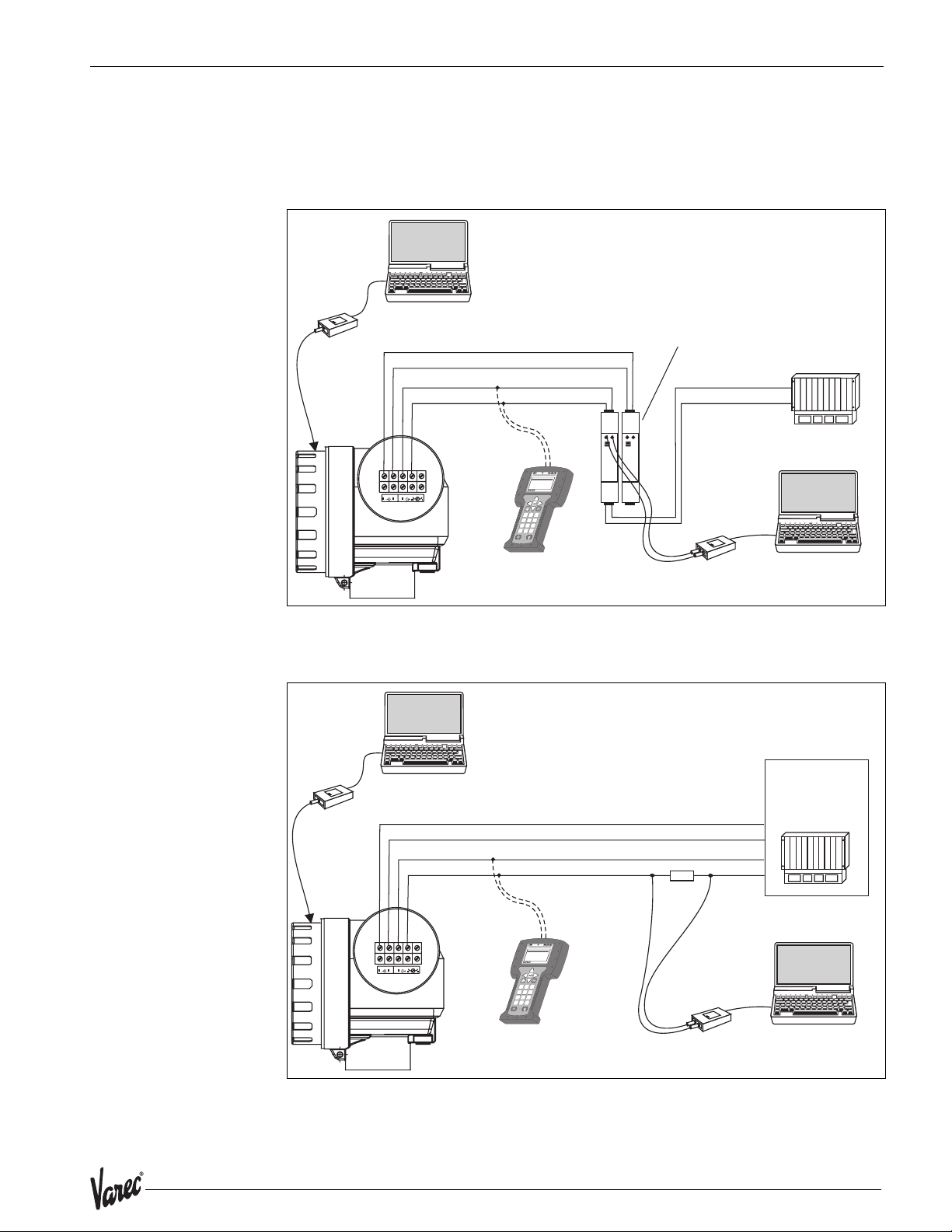
7532 Wiring
4.2.1 Connection to Tank Side Monitor 4590
See page 27.
4.2.2 HART connection with two Varec RN 221 N
- ToF Tool
FXA 193
power supply
RN 221N
4...20 mA
signal
dsdmdm
dsdmdm
df das.
df das.
asdas fa
asdas fa
asas la.
asas la.
DELTABAR:* * * * * * * *
DELTABAR:* * * * * * * *
ONLINE
ONLINE
1 QUICK SETUP
1 QUICK SETUP
2 OPERATING MENU
2 OPERATING MENU
3 PV 352 mbar
3 PV 352 mbar
4 SV 0 ˚C
4 SV 0 ˚C
HELP SAVE
5
132
4
9
9
# % &
# % &
1
1
Copy
Copy
G H I
G H I
4
4
P Q R S
P Q R S
7
7
, ( )‘
_ < >
, ( )‘
_ < >
.
.
0
0
375
375
FIELD COMMUNICATOR
FIELD COMMUNICATOR
HART
HELP SAVE
6
6
Page
Page
Up
Up
DeleteBksp
DeleteBksp
Page
Page
On
On
A B C
D E F
A B C
D E F
3
3
2
2
Paste
Hot Key
Paste
Hot Key
J K L
M N O
J K L
M N O
6
6
5
5
Insert
+ Hot Key
Insert
+ Hot Key
T UV
W XY Z
T UV
W XY Z
8
8
9
9
+ * /
+ * /
-
-
HART handheld
DXR 375
4.2.3 HART connection with other supplies
- ToF Tool
FXA 193
power supply
- COMMUWIN II
- ToF Tool
Commubox
FXA 191
L00-FMR53xxx-04-00-00-en-004
DC voltage
or
PLC
signal
dsdmdm
dsdmdm
df das.
df das.
asdas fa
asdas fa
asas la.
asas la.
DELTABAR:* * * * * * * *
DELTABAR:* * * * * * * *
ONLINE
ONLINE
1 QUICK SETUP
1 QUICK SETUP
2 OPERATING MENU
2 OPERATING MENU
3 PV 352 mbar
3 PV 352 mbar
4 SV 0 °C
4 SV 0 °C
HELP SAVE
# % &
# % &
Copy
Copy
G H I
G H I
4
4
P Q R S
P Q R S
7
7
, ( )‘
, ( )‘
.
.
375
375
FIELD COMMUNICATOR
FIELD COMMUNICATOR
HART
HELP SAVE
6
6
Page
Page
Up
Up
9
9
DeleteBksp
DeleteBksp
Page
Page
On
On
A B C
D E F
A B C
D E F
1
3
1
3
2
2
Paste
Hot Key
Paste
Hot Key
J K L
M N O
J K L
M N O
6
6
5
5
Insert
+ Hot Key
Insert
+ Hot Key
T UV
W XY Z
T UV
W XY Z
8
8
9
9
_ < >
+ * /
_ < >
+ * /
-
-
0
0
5
132
4
HART handheld
DXR 375
≥Ω250
- COMMUWIN II
- ToF Tool
Commubox
FXA 191
Caution!
If the HART communication resistor is not built into the supply unit, it is necessary to
insert a communication resistor of 250 Ω into the 2-wire line.
4...20 mA
L00-FMR53xxx-04-00-00-en-005
29
Page 30

Wiring Radar Tank Gauge
4.3 Equipotential bonding
Connect the Equipotential bonding to the external ground terminal of the transmitter.
Caution!
In Ex applications, the instrument must only be grounded on the sensor side. Further
safety instructions are given in the separate documentation for applications in explosion
hazardous areas.
4.4 Degree of protection
• housing: IP 65, NEMA 4X (open housing: IP20, NEMA 1)
• antenna: IP 68 (NEMA 6P)
4.5 Overvoltage protector
• The level transmitter 7500 RTG is equipped with an internal overvoltage protector
(600 Vrms electrode). Connect the metallic housing of the 7500 RTG to the tank wall
directly with an electrically conductive lead to ensure reliable potential matching.
• Installation with additional overvoltage protector HAW 262 Z (see XA 081F-A
"Safety instructions for electrical apparatus certified for use in explosion-hazardous
areas").
–Connect the external overvoltage protector and the 7500 RTG transmitter to the local
potential matching system.
–Potentials shall be equalised both inside and outside the explosion hazardous area.
–The cable connecting the overvoltage protector and the 7500 RTG transmitter shall
not exceed 1 m in length;
–The cable shall be protected e.g. routed in an armoured hose.
4.6 Post-connection check
After wiring the measuring instrument, perform the following checks:
• Is the terminal allocation correct (see page 25)?
• Is the cable gland tight?
• Is the housing cover screwed tight?
• If auxiliary power is available:
Is the instrument ready for operation and does the liquid crystal display show any
value?
30 Installation and Operations Manual
Page 31

7532 Operation
5Operation
5.1 Quick operation guide
31
Page 32
Operation Radar Tank Gauge
+–
E
X
F
2x
X
X
X
>3 s
O
...
S
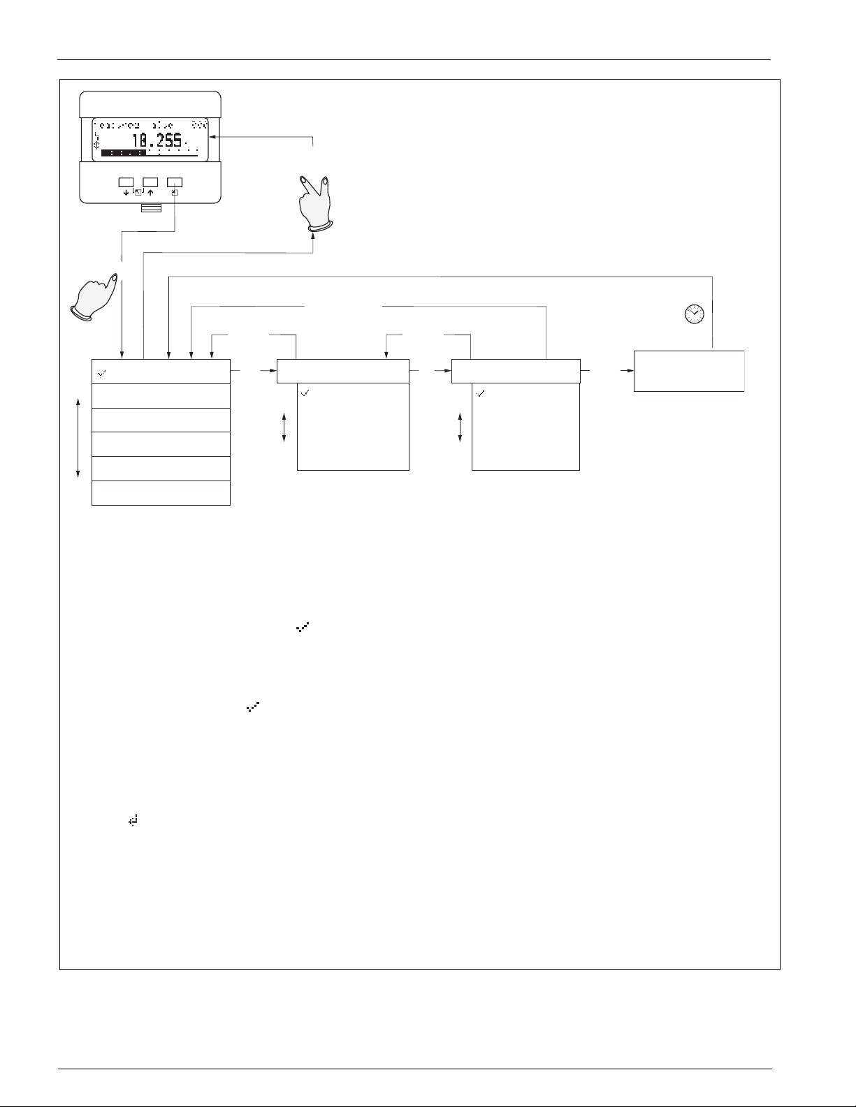
Selection and configuration in Operation menu:
1.) Change from Measured Value Display to by pressing
2.) Press or to select the required (e.g.. "basic setup (00)") and confirm by pressing
F
Note!
The active selection is marked by a in front of the menu text.
3.) Activate Edit mode with or .
Selection menus:
a) Select the required in selected (e.g. "tank shape (002)") with or .
b) confirms selection appears in front of the selected parameter
c) confirms the edited value system quits Edit mode
d) + (= ) interrupts selection system quits Edit mode
Typing in numerals and text:
a) Press or to edit the first character of the (e.g. "empty calibr. (005)")
b) positions the cursor at the next character (a) until you have completed your input
c) if a symbol appears at the cursor, press to accept the value entered
d) + (= ) interrupts the input,
4) Press to select the next (e.g. "medium property (003)")
5) Press + (= ) once return to previous (e.g. "tank shape (002)")
Press + (= ) twice return to
6) Press + (= ) to return to
...
SO
First f
➜
unction
F
F
OS X
OS
F
➜
system quits Edit mode
S
OX
F
OS X
OS
OX
X
S
FF
(e.g. "tank shape (002)") is selected.
O
Parameter
➜
OO
SS
Group Selection
Function Group
F
S
function
➜
➜
numeral / text
➜
continue with
F
system quits Edit mode
function
➜
➜
Group selection
Measured value display
function
...
SO
L00-FMR2xxxx-19-00-00-en-001
32 Installation and Operations Manual
Page 33
7532 Operation
5.1.1 General structure of the operating menu
The operating menu is made up of two levels:
• Function groups (00, 01, 03, …, 0C, 0D):
The individual operating options of the instrument are split up roughly into different
function groups. The function groups that are available include, e.g.: "basic setup",
"safety settings", "output", "display", etc.
• Functions (001, 002, 003, …, 0D8, 0D9):
Each function group consists of one or more functions. The functions perform the
actual operation or parameterization of the instrument. Numerical values can be
entered here and parameters can be selected and saved. The available functions of the
“basic setup (00)” function group include, e.g.: "tank shape (002)",
"medium property (003)", "process cond. (004)", "empty calibr. (005)", etc.
If, for example, the application of the instrument is to be changed, carry out the following procedure:
1.Select the “basic setup (00)” function group.
2.Select the "tank shape (002)" function (where the existing tank shape is selected).
5.1.2 Identifying the functions
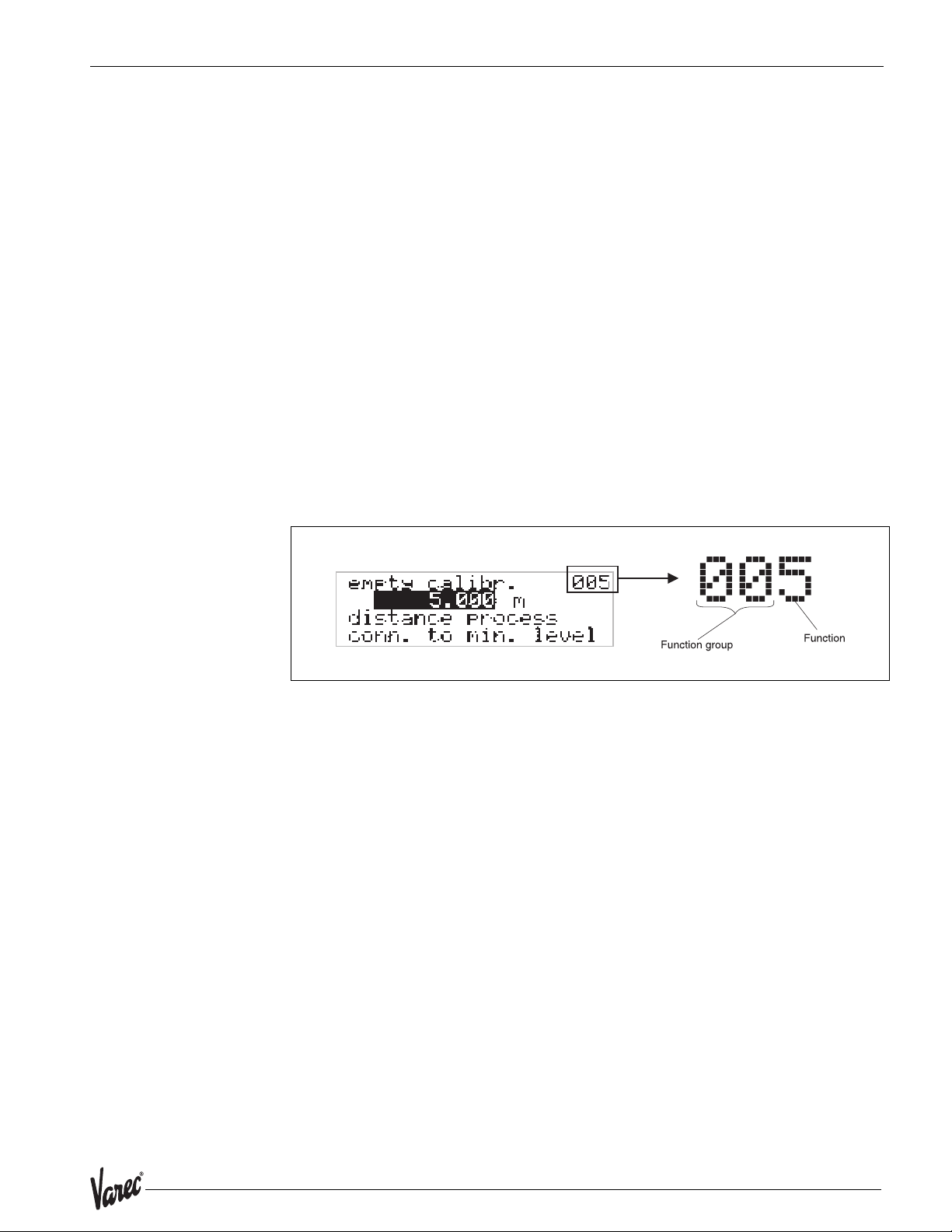
For simple orientation within the function menus (see page 91), for each function a
position is shown on the display.
The first two digits identify the function group:
• basic setup 00
• safety settings 01
• linearization 04
…
The third digit numbers the individual functions within the function group:
• basic setup 00 → • tank shape 002
• medium property 003
• process cond. 004
…
Here after the position is always given in brackets (e.g. "tank shape" (002)) after the
described function.
L00-FMR2xxxx-07-00-00-en-005
33
Page 34
Operation Radar Tank Gauge
5.2 Display and operating elements
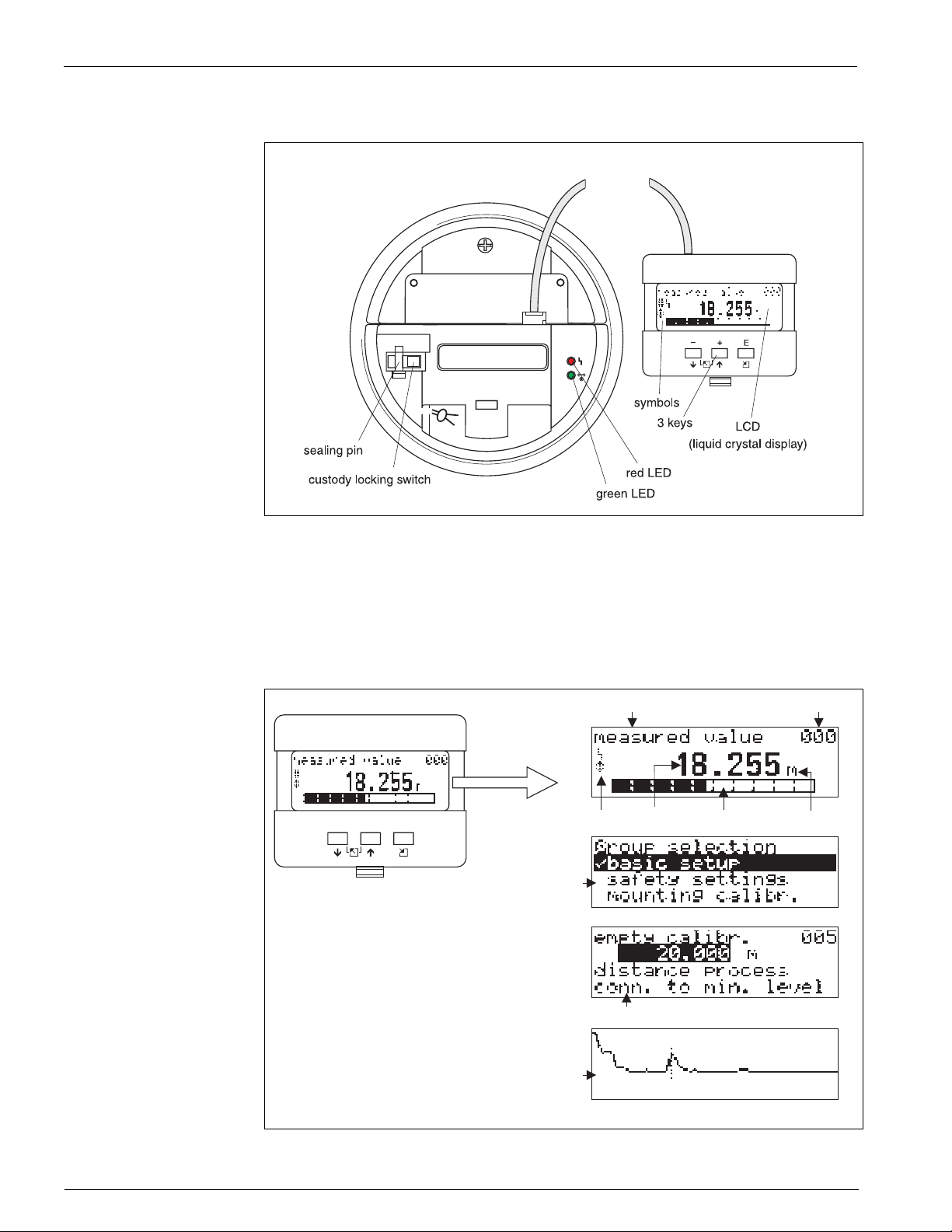
Figure 5: Layout of the display and operating elements
5.2.1 Display
Liquid crystal display (LCD):
Four lines with 20 characters each. Display contrast adjustable through key
combination.
Headline Position indicator
+–
E
Selection list
Symbol
Main value
Bargraph
L00-FMR53xxx-07-00-00-en-003
Unit
Help text
Envelope
curve
Figure 6: Display
34 Installation and Operations Manual
L00-FMRxxxxx-07-00-00-en-003
Page 35
7532 Operation
5.2.2 Display symbols
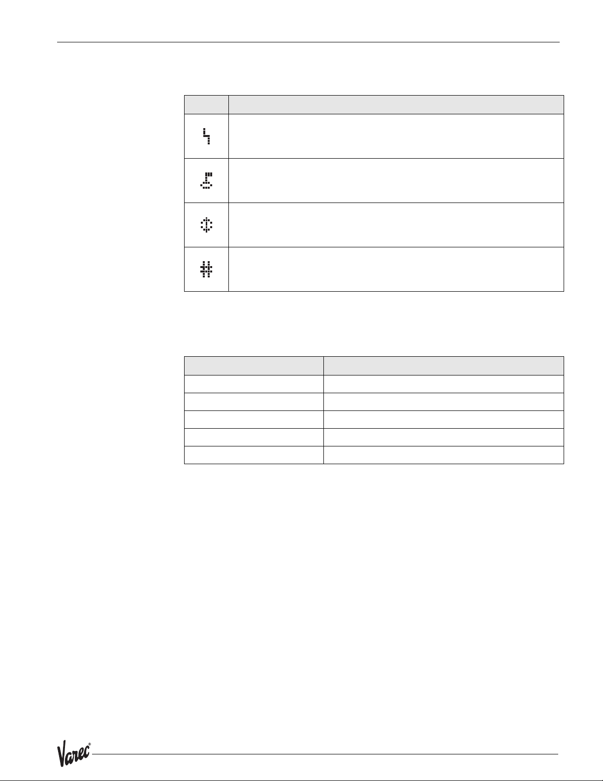
The following table describes the symbols that appear on the liquid crystal display:
Symbols Meaning
ALARM_SYMBOL
This alarm symbol appears when the instrument is in an alarm state. If the symbol
flashes, this indicates a warning.
LOCK_SYMBOL
This lock symbol appears when the instrument is locked,i.e. if no input is possible.
COM_SYMBOL
This communication symbol appears when a data transmission via e.g. HART,
PFOFIBUS-PA or Foundation Fieldbus is in progress.
Calibration to regulatory standards disturbed
If the instrument is not locked or it cannot guarantee the calibration to regulatory
standards, the situation will be indicated on the display via the symbol.
Table 1: Meaning of the symbols
Light emitting diodes (LEDs):
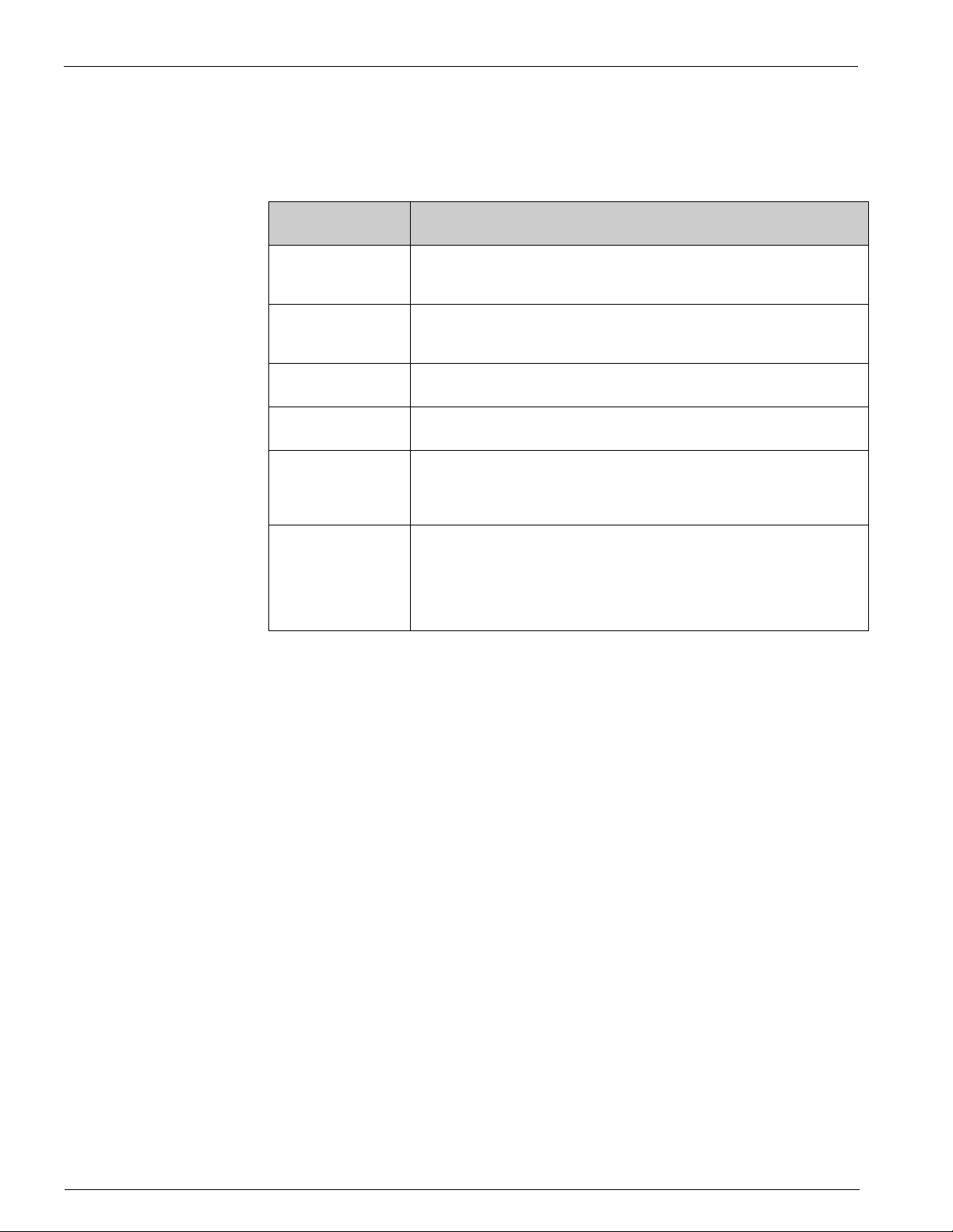
There is a green and a red LED besides the Liquid Crystal Display.
LED Meaning
red LED continuously on Alarm
red LED flashes Warning
red LED off No alarm
green LED continuously on Operation
Green LED flashes Communication with external device
35
Page 36
Operation Radar Tank Gauge
5.2.3 Key assignment
The operating elements are located inside the housing and are accessible for operation
by opening the lid of the housing.
Function of the keys
Key(s) Meaning
O or V
S or W
Navigate upwards in the selection list
Edit numeric value within a function
Navigate downwards in the selection list
Edit numeric value within a function
X or Z Navigate to the left within a function group
F or M Navigate to the right within a function group, confirmation.
O and F
or
Contrast settings of the LCD
S and F
Hardware lock / unlock
After a hardware lock, an operation of the instrument via display or
O and S and F
Table 2: Function of the keys
Custody locking switch
Access to the electronics can be prevented by means of a custody locking switch that
locks the device settings; see fig. 4 on Page 34.
The custody locking switch can be sealed for custody transfer applications.
communication is not possible!
The hardware can only be unlocked via the display. An unlock parameter must
be entered to do so.
Software reliability
The software used in the 7500 RTG fulfills the requirements of
OIML R85. This particularly includes:
• cyclical test of data consistency
• non-volatile memory
• segmented data storage
The 7500 RTG continuously monitor the compliance with accuracy requirements for
custody transfer measurements according to OIML R85. If the accuracy cannot be
maintained, a specific alarm is generated on the local display and via the digital
communication
36 Installation and Operations Manual
Page 37
7532 Operation
5.3 Local operation
5.3.1 Locking of the configuration mode
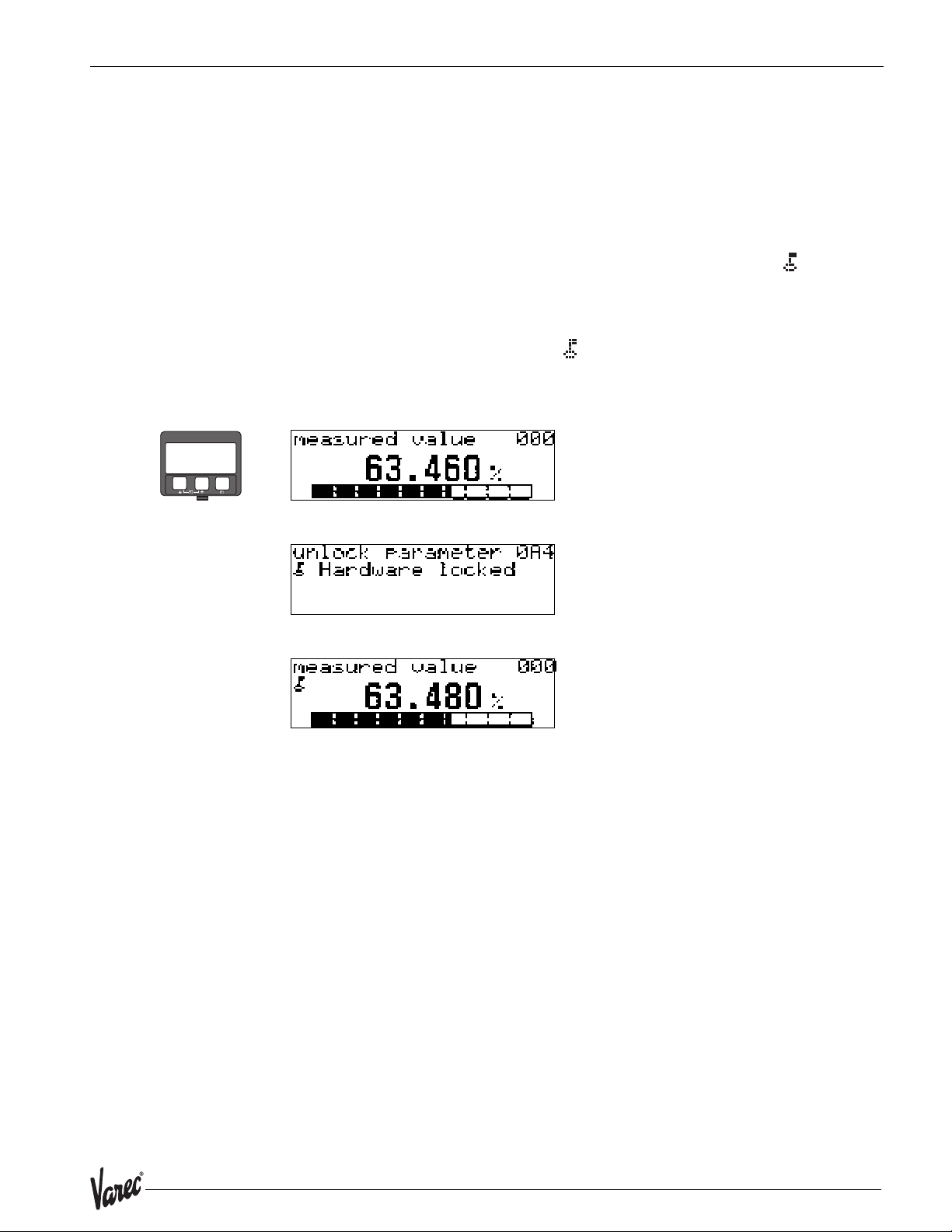
The 7500 RTG can be protected in two ways against unauthorized changing of instrument data, numerical values or factory settings:
"unlock parameter" (0A4):
A value <> 100 (e.g. 99) must be entered in "unlock parameter" (0A4) in the
"diagnostics" (0A) function group. The lock is shown on the display by the
can be released again either via the display or by communication.
Hardware lock:
The instrument is locked by pressing the
The lock is shown on the display by the
via the display by pressing the O and S and F keys at the same time again. It is not
possible to unlock the hardware by communication.
All parameters can de displayed even if the instrument is locked.
O and S and F keys at the same time.
symbol and can only be unlocked again
symbol and
–
+
E
O and S and F press simultaneous
⇓
⇓
The LOCK_SYMBOL appears on the LCD.
⇒
37
Page 38
Operation Radar Tank Gauge
5.3.2 Unlocking of configuration mode
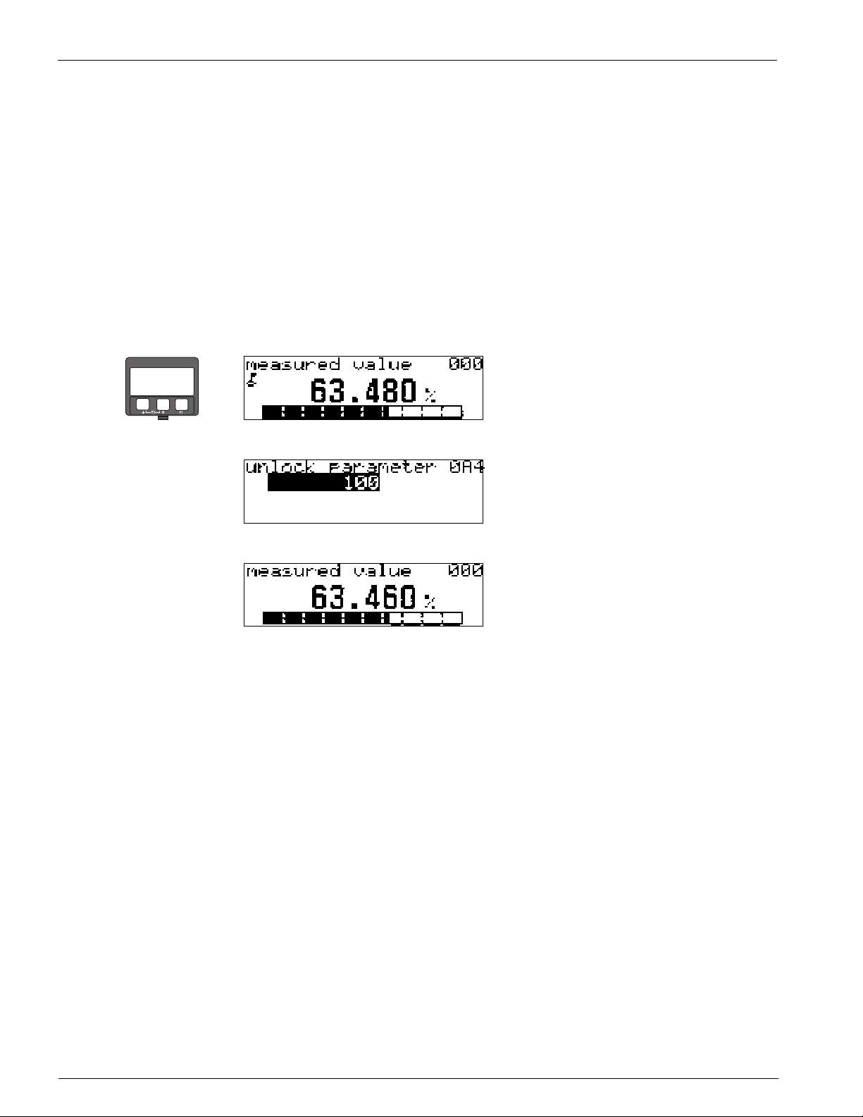
If an attempt is made to change parameters when the instrument is locked, the user is
automatically requested to unlock the instrument:
"unlock parameter" (0A4):
By entering the unlock parameter (on the display or via communication)
100 = for HART devices
the 7500 RTG is released for operation.
Hardware lock:
After pressing the
unlock parameter
100 = for HART devices.
O and S and F keys at the same time, the user is asked to enter the
–
⇒
+
E
O and S and F press simultaneous
⇓
Please enter unlock code and confirm with F.
⇓
Caution!
Changing certain parameters such as all sensor characteristics, for example, influences
numerous functions of the entire measuring system, particularly measuring accuracy.
There is no need to change these parameters under normal circumstances and
consequently, they are protected by a special code known only to the Varec service
organization. Please contact Varec if you have any questions.
38 Installation and Operations Manual
Page 39
7532 Operation
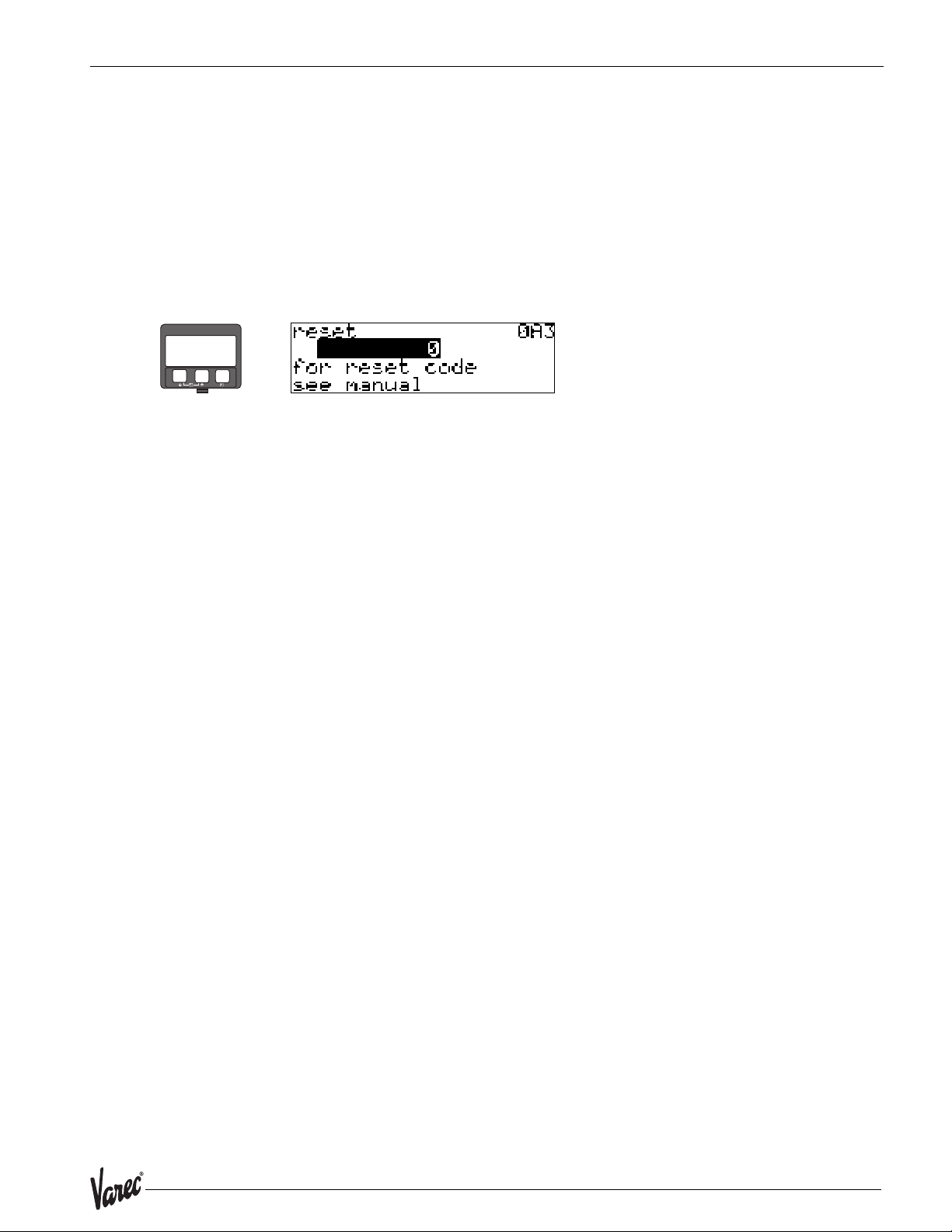
5.3.3 Factory settings (Reset)
Caution!
A reset sets the instrument back to the factory settings. This can lead to an impairment
of the measurement. Generally, you should perform a basic setup again following a
reset.
A reset is only necessary:
• if the instrument no longer functions
• if the instrument must be moved from one measuring point to another
• if the instrument is being de-installed /put into storage/installed
–
⇒
+
E
User input ("reset" (0A3)):
• 333 = customer parameters
•555 = History
333 = reset customer parameters
This reset is recommended whenever an instrument with an unknown 'history' is to be
used in an application:
• The 7500 RTG is reset to the default values.
• The customer specific tank map is not deleted.
• A linearization is switched to "linear" although the table values are retained. The table
can be reactivated in the "linearization" (04) function group.
List of functions that are affected by a reset:
• tank shape (002)
• empty calibr. (005)
• full calibr. (006)
• pipe diameter (007)
• output on alarm (010)
• output on alarm (011)
• outp. echo loss (012)
• ramp %span/min (013)
• delay time (014)
• safety distance (015)
• in safety dist. (016)
• Tank Gauging (030)
• auto correction (031)
• level/ullage (040)
•linearization (041)
• customer unit (042)
• diameter vessel (047)
• range of mapping (052)
• pres. Map dist (054)
• offset (057)
• low output limit (062)
• fixed current (063)
• fixed cur. value (064)
• simulation (065)
• simulation value (066)
• format display (094)
• distance unit (0C5)
• download mode (0C8)
555 = History Reset
After mounting and aligning the equipment, carry out a history reset before switching
on the function "Auto-correction" (031) (see page 57).
The tank map can also be reset in the "cust. tank map" (055) function of the
"extended calibr." (05) function group.
This reset is recommended whenever an instrument with an unknown 'history' is to be
used in an application or if a faulty mapping was started:
• The tank map is deleted. The mapping must be recommenced.
39
Page 40
Operation Radar Tank Gauge
5.4 Display and acknowledging error messages
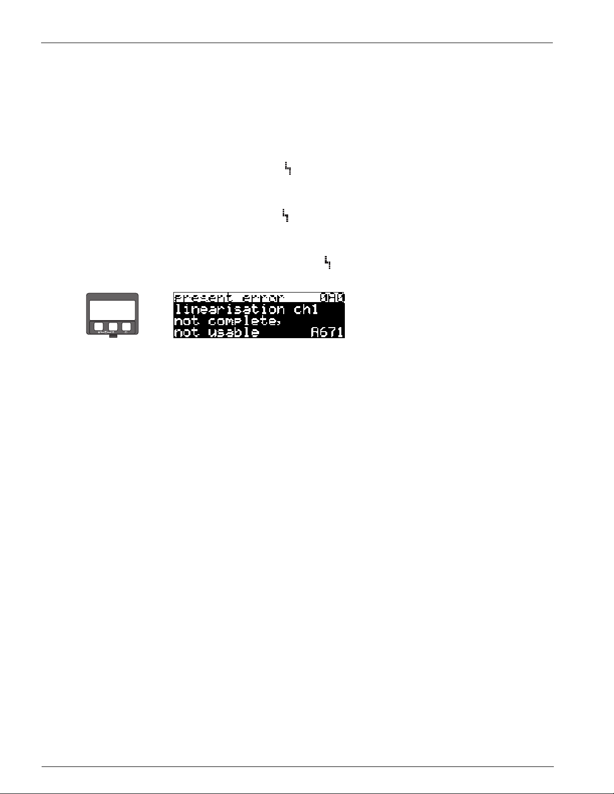
Type of error
Errors that occur during commissioning or measuring are displayed immediately on the
local display. If two or more system or process errors occur, the error with the highest
priority is the one shown on the display.
The measuring system distinguishes between two types of error:
• A (Alarm):
Instrument goes into a defined state (e.g. MAX 22 mA)
Indicated by a constant
(For a description of the codes, see Table 9.2 on Page 79)
• W (Warning):
Instrument continue measuring, error message is displayed.
Indicated by a flashing symbol.
(For a description of the codes, see Table 9.2 on Page 79)
• E (Alarm / Warning):
Configurable (e.g. loss of echo, level within the safety distance)
Indicated by a constant/flashing symbol.
(For a description of the codes, see Table 9.2 on Page 79)
symbol.
–
⇒
+
E
Error messages
Error messages appear as four lines of plain text on the display. In addition, a unique
error code is also output. A description of the error codes is given on page 79.
•The "diagnostics (0A)" function group can display current errors as well as the last
errors that occurred.
• If several current errors occur, use
• The last occurring error can be deleted in the "diagnostics (0A)" function group
with the function "clear last error" (0A2).
O or S to page through the error messages.
40 Installation and Operations Manual
Page 41
7532 Operation
5.5 HART communication
Apart from local operation, you can also parameterize the measuring instrument and
view measured values by means of a HART protocol. There are two options available for
operation:
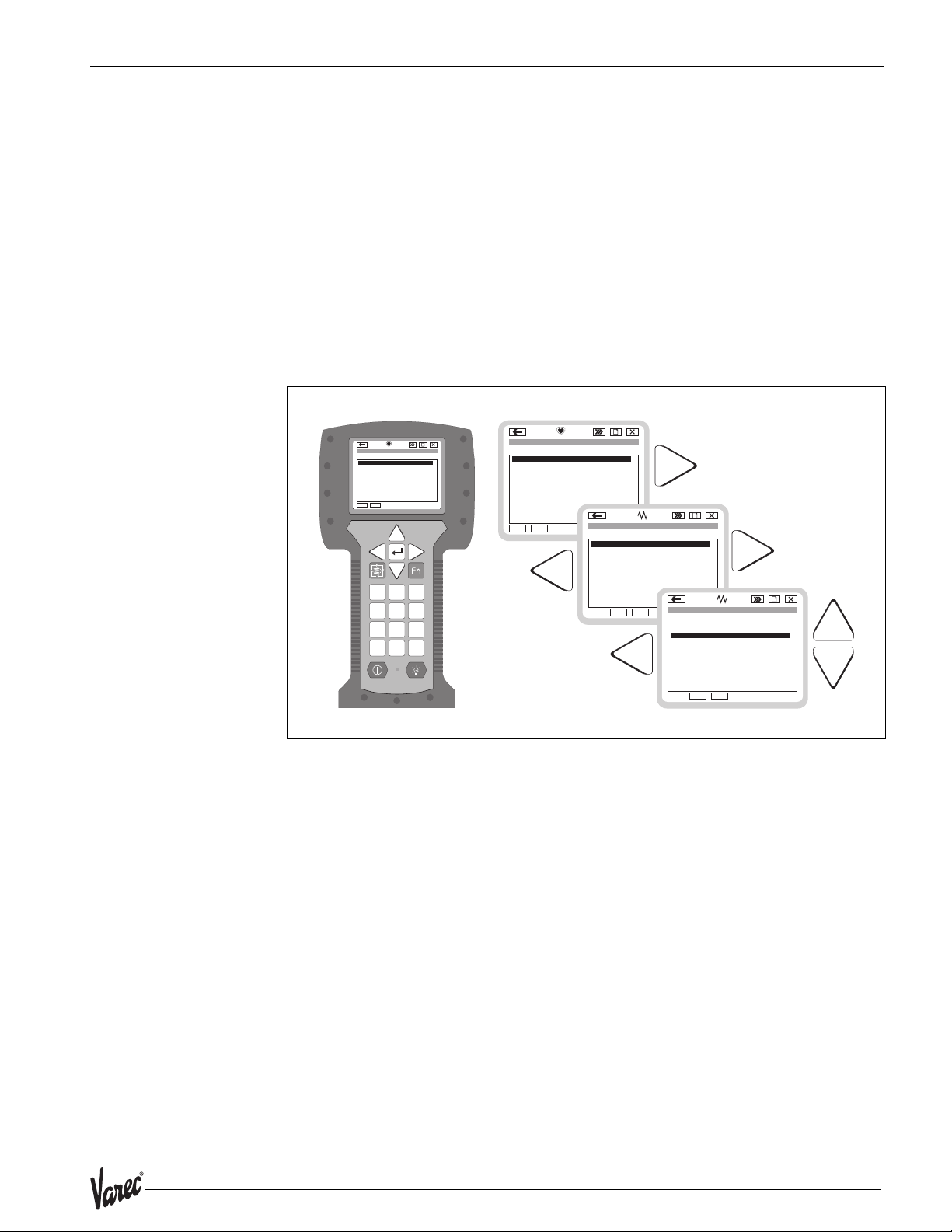
• Operation via the universal handheld operating unit, the
HART Communicator DXR 375.
• Operation via the Personal Computer (PC) using the operating program
(e.g. ToF Tool or Commuwin II) (For connections, see page 29).
• Operation via the Tank Side Monitor 4590.
5.5.1 Handheld unit DXR 375
All device functions can be adjusted via menu operation with the handheld unit
DXR 375.
dsdmdm
df das.
asdas fa
asas la.
Delete
FMR531:LIC0001
ONLINE
1 GROUP SELECT
2 PV 8.7 m
dsdmdm
df das.
asdas fa
asas la.
FMR531: LIC0001
ONLINE
1 GROUP SELECTION
2 PV 8.7 m
HELP SAVE
Page
Up
9
Page
On
# % &
A B C
2
1
Copy
Paste
G H I
J K L
5
4
Insert
P Q R S
T UV
8
7
, ( )‘
_ < >
.
0
375
FIELD COMMUNICATOR
6
DeleteBksp
D E F
3
Hot Key
M N O
6
+ Hot Key
W XY Z
9
+ * /
-
HELP SAVE
Bksp
H
FMR531: LIC0001
GROUP SELECTION
1 CALIBRATION
2 LINEARISATION
3 EXT.CALIBRATION
4 SERVICE
5 OPERATING MODE
HOMESAVE
Bksp
dsdmdm
df das.
asdas fa
asas la.
H
FMR531: LIC0001
CALIBRATION
1 MEASURED VALUE
2 EMPTY CALIBRATION
3 FULL CALIBRATION
4 APPLICATION PARAMETER
5 OUTPUT DAMPING
HOMESAVE
Delete
dsdmdm
df das.
asdas fa
asas la.
Page
Up
Page
On
Figure 7: Menu operation with the DXR 375 handheld instrument
Note!
• Further information on the HART handheld unit is given in the respective operating
manual included in the transport bag of the instrument.
5.5.2 ToF Tool operating program
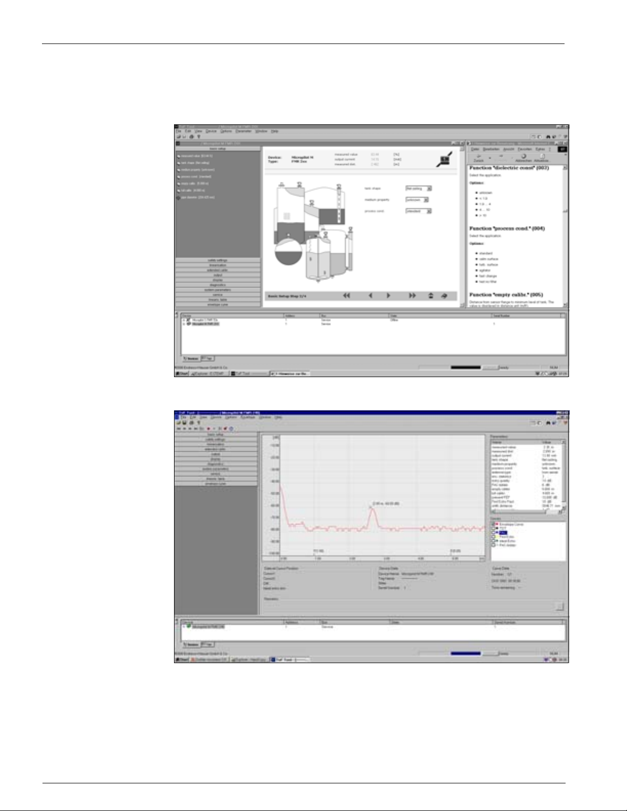
The ToF Tool is a graphical operating software for instruments from Varec that operate
based on the time-of-flight principle. It is used to support commissioning, securing of
data, signal analysis and documentation of the instruments. It is compatible with the
following operating systems: Win95, Win98, WinNT4.0, Win2000 and
Windows XP.
The ToF Tool supports the following functions:
• Online configuration of transmitters
• Signal analysis via envelope curve
• Loading and saving of instrument data (Upload/Download)
• Documentation of measuring point
L00-FMR53xxx-07-00-00-xx-001
41
Page 42
Operation Radar Tank Gauge
Note!
Further information you may find on the CD-ROM, which is enclosed to the instrument.
Menu-guided commissioning
Signal analysis via envelope curve
Connection options:
• Service-interface with adapter FXA 193 (see page 29)
• HART with Commubox FXA 191 (see page 29)
42 Installation and Operations Manual
Page 43
7532 Operation
5.5.3 Commuwin II-Operating Program
Commuwin II is an operating software with graphical support for intelligent transmitters
with the communication protocols Rackbus, Rackbus RS 485, INTENSOR, HART or
PROFIBUS-PA. It is compatible with the operating systems Win 3.1/3.11, Win95, Win98
and WinNT4.0. All functions of Commuwin II are supported. The configuration is made
via operating matrix or graphic surface. A envelope curve can be displayed in ToF Tool.
Note!
Further information on Commuwin II is given in the following Varec documentation:
•System Information: SI 018F/00/en “Commuwin II”
• Operating Manual: BA 124F/00/en “Commuwin II” operating program
Connection
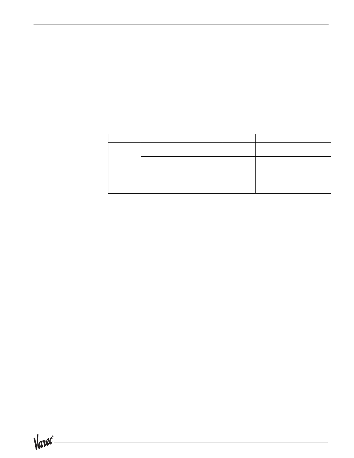
The table provides an overview of the Commuwin connections.
Interface Hardware Server Device list
HART Commubox FXA 191 to HART
Computer with RS-232C interface
Interface FXN 672
Gateway for MODBUS, PROFIBUS,
FIP, INTERBUS, etc.
Computer with
RS-232C interface or
PROFIBUS card
HART Connected instrument
ZA 673 for
PROFIBUS
ZA 672 for
other
List of all rack bus modules:
the required FXN 672 must
be selected
Note!
The 7500 RTG can also be operated locally using the keys. If operation is prevented by
the keys being locked locally, parameter entry via communication is not possible either.
43
Page 44

Operation Radar Tank Gauge
44 Installation and Operations Manual
Page 45
7532 Commissioning
6 Commissioning
6.1 Function check
Make sure that all final checks have been completed before you start up your measuring
point:
• Checklist “Post installation check” (see page 24).
• Checklist “Post connection check” (see page 30).
6.2 Commissioning
6.2.1 Switching on the measuring device
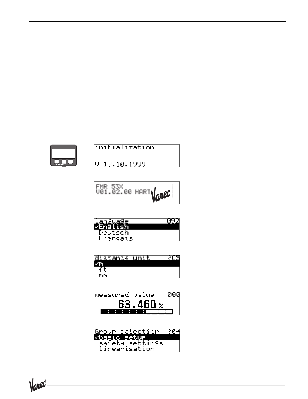
When the instrument is switched on for the first time, the following messages appear on
the display:
–
+
E
After 5 s, the following message appears
⇓
⇒
After 5 s or after you have pressed F the follow-
⇓
ing message appears
Select the language
(this message appears the first time the instrument
is switched on)
⇓
Select the basic unit
(this message appears the first time the instrument
is switched on)
⇓
⇓
The current measured value is displayed
After F is pressed, you reach the group selection.
This selection enables you to perform the basic
setup
45
Page 46

Commissioning Radar Tank Gauge
6.3 Basic Setup
46 Installation and Operations Manual
Page 47
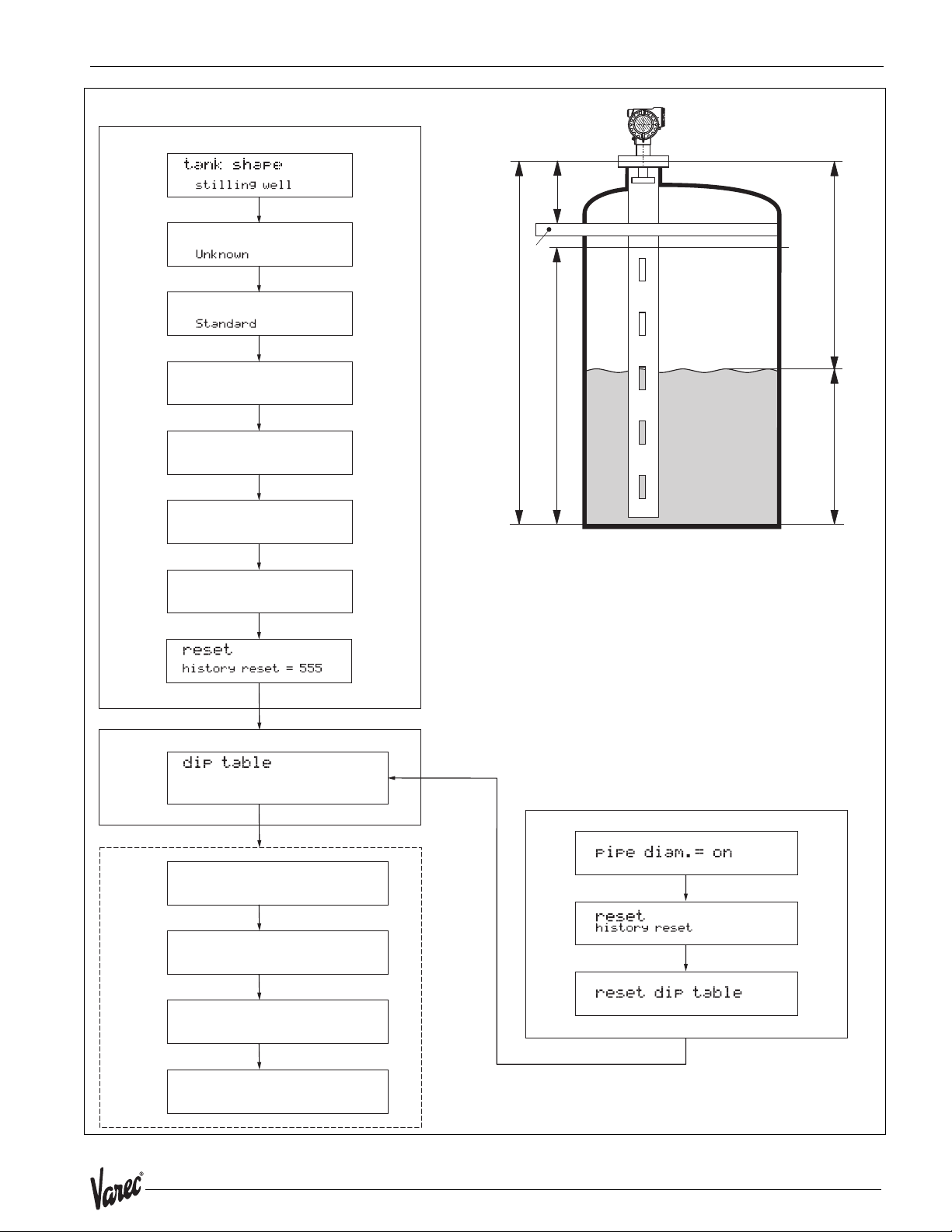
7532 Commissioning
Commissioning
flange:
referencepointof
measurement
BD
measuring cond.
SD
measuring cond.
E
D
empty calibr.
full calibr.
basic setup (standard)
pipe diameter
(for bypass/stilling well)
mapping
first point corrects
further points correct linearity
mounting
calibr.
offset
F
E = empty calibr.(= zero)
settings in 005 settings in 006
D = distance (distance flange / product) L
display in 0A5 in 0A6
SD = safety settings BD = blocking dist.
settings in 015 settings in 059
F = full calibr.(= span)
=level
display
Automatic
pipe diamter correction
(option)
L
option
safety settings
linearisation
extended calibr.
L00-FMR532xx-19-00-00- en-003
...
(description see BA 217F)
47
Page 48

Commissioning Radar Tank Gauge
To successfully commission a precise measurement to the nearest mm, it is important
you carry out a history reset on first installation after mechanical installation and after
the basic setup of the device (see Page 56). Only after a history reset the mounting cali-
bration is carried out. Enter the measurement offset as the first point in the dip table for
the mounting calibration. When a value is dipped at a later date, make a second entry
into the dip table, again using the semi-automatic mode. This way, you can easily carry
out a linearization of the measurement.
When configuring the function in "basic setup" (00) please take into account the
following notes:
• Select the functions as described on page 31.
• Some functions can only be used depending on the parameterization of the
instrument. For example, the pipe diameter of a stilling well can only be entered if
"stilling well" was selected beforehand in the "tank shape" (002) function.
• Certain functions (e.g. starting an interference echo mapping (053)) prompt you to
confirm your data entries. Press
function is now started.
• If you do not press a key during a configurable time period (→ function group
"display (09)"), an automatic return is made to the home position (measured value
display).
Note!
• The instrument continues to measure while data entry is in progress, i.e. the current
measured values are output via the signal outputs in the normal way.
• If the envelope curve mode is active on the display, the measured values are updated
in a slower cycle time. Thus, it is advisable to leave the envelope curve mode after the
measuring point has been optimized.
• If the power supply fails, all preset and parameterized values remain safely stored in
the EEPROM.
O or S to select "YES" and press F to confirm. The
Note!
All functions are described in detail, as is the overview of the operating menu itself, in
the 7500 RTG "Service manual and description of instrument functions".
48 Installation and Operations Manual
Page 49
7532 Commissioning
6.4 Basic Setup with the VU 331
Function "measured value" (000)
–
+
E
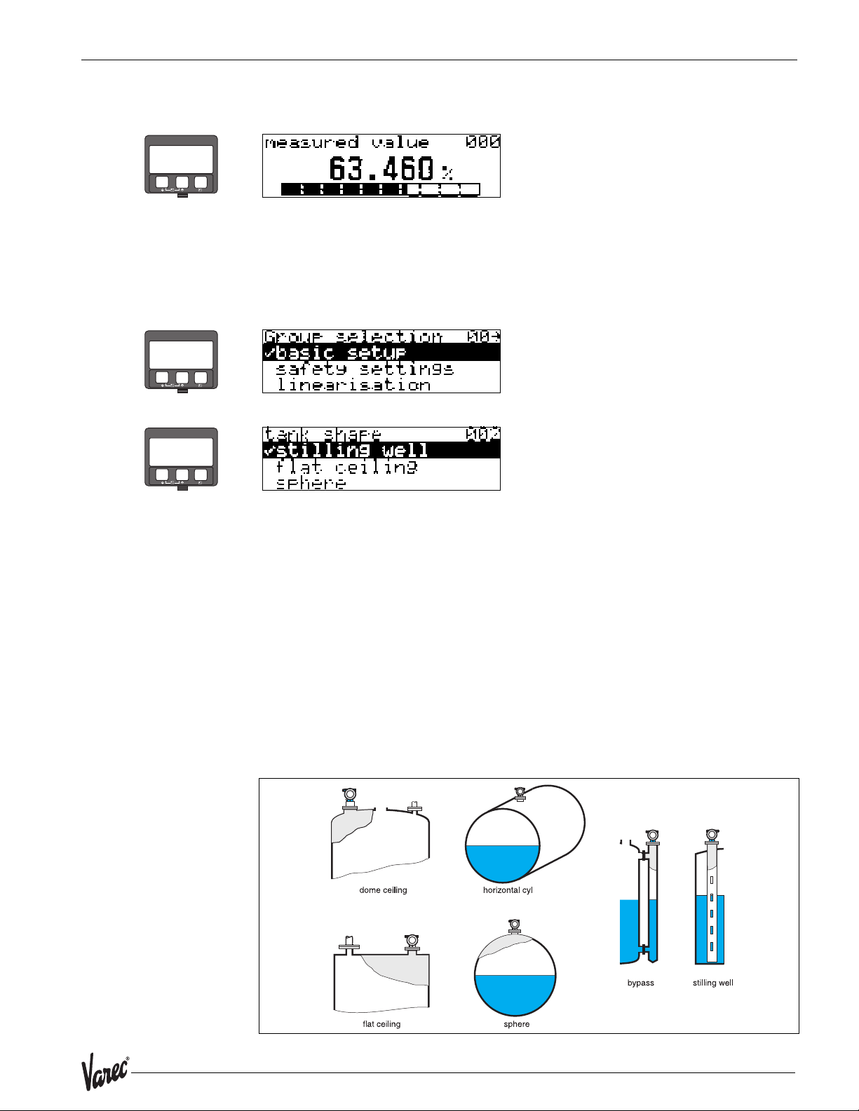
This function displays the current measured value in the selected unit
(see "customer unit" (042) function). The number of digits after decimal point can be
selected in the "no.of decimals" (095) function. The length of the bargraph corresponds
to the percentile value of the present measured value with regard to the span.
6.4.1 Function group "basic setup" (00)
⇒
⇒
–
+
E
Function "tank shape" (002)
⇒
–
+
E
This function is used to select the tank shape.
Note!
For the application of the 7532 RTG the selection "stilling well" has to be chosen in the
function "tank shape" (002).
Selection:
• dome ceiling
• horizontal cyl
•bypass
• stilling well
• flat ceiling (Typical ceiling of storage tanks: a slight slope of only a few degrees can
be neglected.)
•sphere
L00-FMR2xxxx-14-00-00-en-007
49
Page 50
Commissioning Radar Tank Gauge
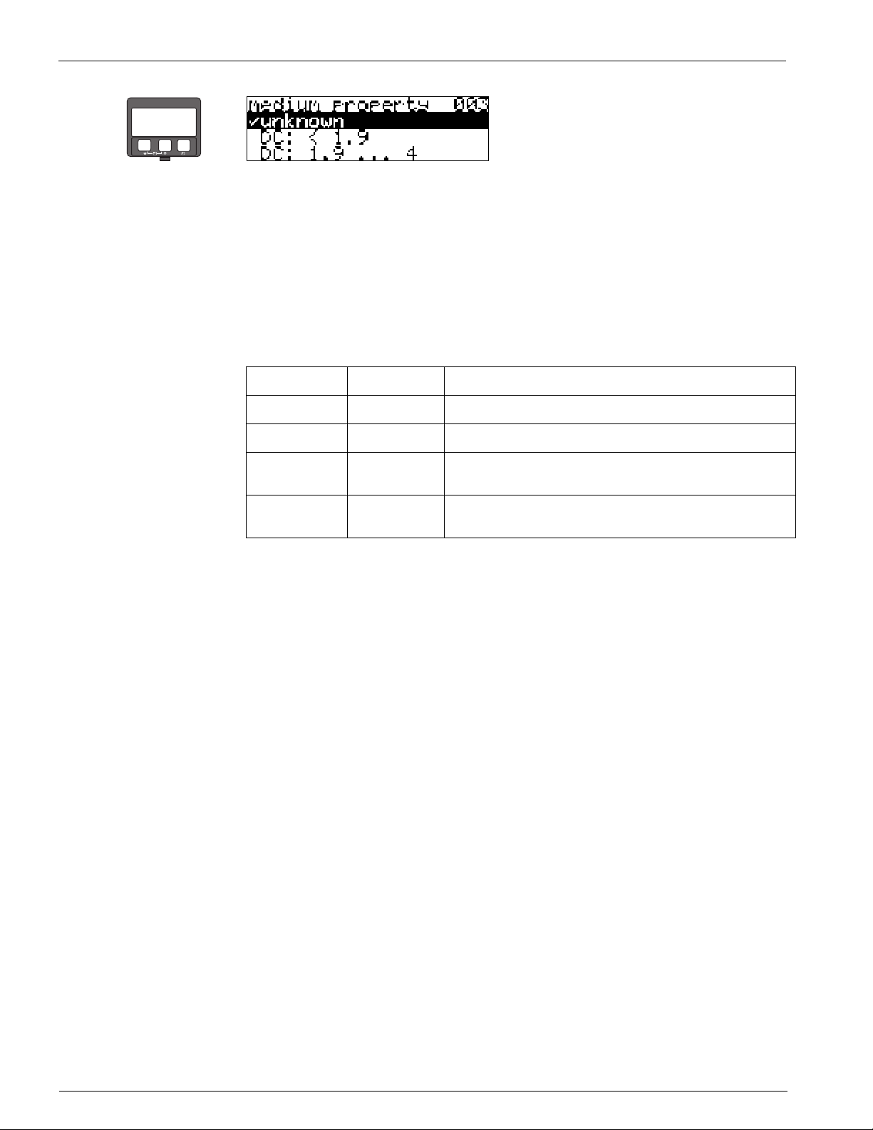
Function "medium property" (003)
⇒
–
+
E
This function is used to select the dielectric constant.
Selection:
• unknown
•< 1.9
• 1.9 ... 4
• 4 ... 10
•> 10
Product class DK (er) Examples
A 1,4 … 1,9 non-conducting liquids, e.g. liquefied gas
B 1,9 … 4 non-conducting liquids, e.g. benzene, oil, toluene, …
3)
C 4 … 10 e.g. concentrated acids, organic solvents, esters, aniline,
D > 10 conducting liquids, e.g. aqueous solutions, dilute acids and
3)Treat Ammonia NH3 as a medium of group A, i.e. always use a stilling well.
alcohol, acetone, …
alkalis
50 Installation and Operations Manual
Page 51
7532 Commissioning
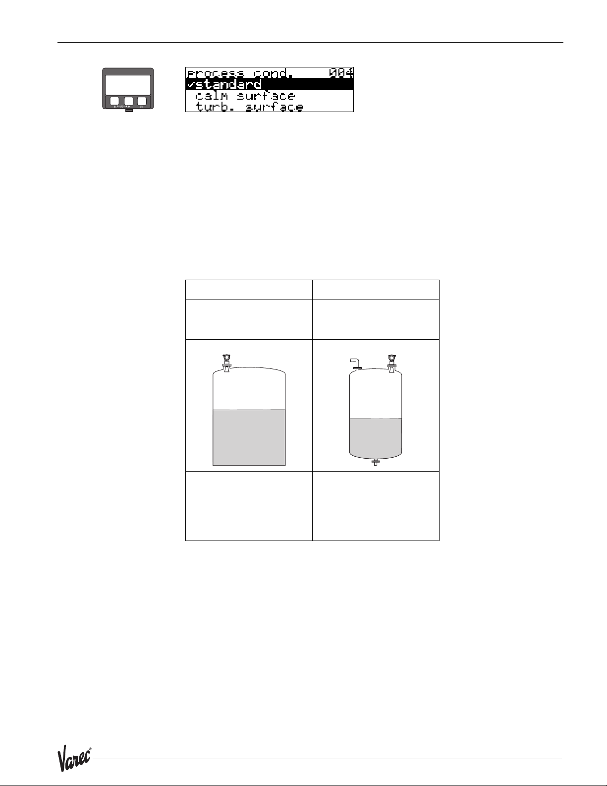
Function "process cond." (004)
⇒
–
+
E
This function is used to select the process conditions.
Selection:
• standard
• calm surface
•turb. surface
• agitator
• fast change
• test:no filter
standard calm surface
For all applications that do
not fit into any of the
following groups.
The filter and output
damping are set to average
values.
Storage tanks with immersion
tube or bottom filling
The averaging filters and
output damping are set to
high values.
-> steady meas. value
-> precise measurement
-> slower reaction time
Note!
The phase evaluation of the 7500 RTG (see »Function "auto-correction" (031)« on
page 57) is only activated if you select the measuring conditions "standard" or
"calm surface". We strongly recommend that, in the case of rough product surfaces or
rapid filling, you activate the appropriate application parameters.
51
Page 52
Commissioning Radar Tank Gauge
Function "empty calibr." (005)
⇒
–
+
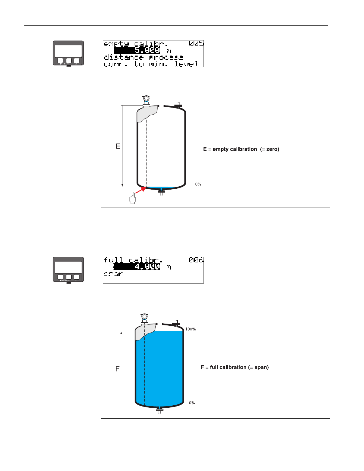
E
This function is used to enter the distance from the flange (reference point of the
measurement) to the minimum level (=zero).
L00-FMR2xxxx-14-00-06-en-008
Caution!
For dish bottoms or conical outlets, the zero point should be no lower than the point at
which the radar beam hits the bottom of the tank.
Function "full calibr." (006)
⇒
–
+
E
This function is used to enter the distance from the minimum level to the maximum level
(=span).
In principle, it is possible to measure up to the tip of the antenna. However, due to
considerations regarding corrosion and build-up, the end of the measuring range
should not be chosen any closer than 50 mm (2”) to the tip of the antenna.
52 Installation and Operations Manual
L00-FMR2xxxx-14-00-06-en-009
Page 53
7532 Commissioning
Note!
If bypass or stilling well was selected in the "tank shape" (002) function, the pipe
diameter is requested in the following step.
Function "pipe diameter" (007)
⇒
–
+
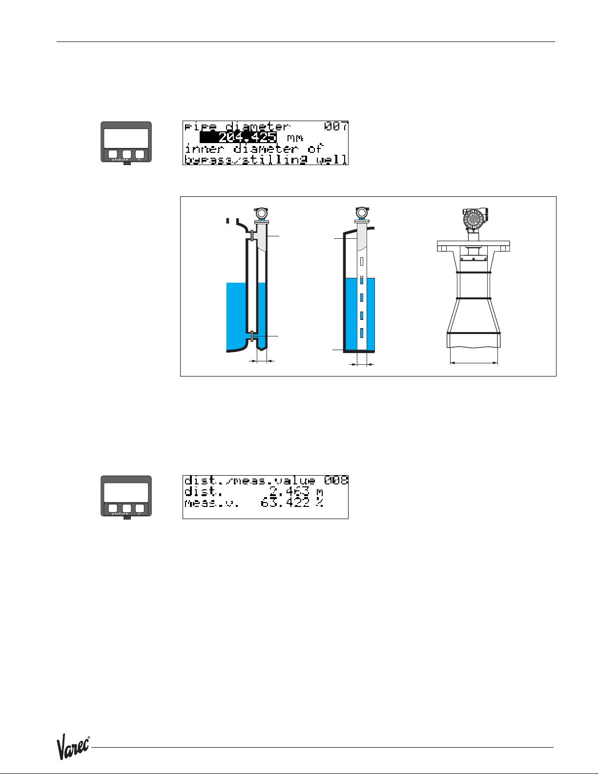
E
This function is used to enter the pipe diameter of the stilling well or bypass pipe.
100%
0%
ø
100%
0%
ø
d2
L00-FMR532xx-14-00-00 -xx-001
Microwaves propagate slower in pipes than in free space. This effect depends on the
inside diameter of the pipe and is automatically taken into account by the 7500 RTG. It
is only necessary to enter the pipe diameter for applications in a bypass or stilling well.
If mounting the 7532 RTG on stilling wells with a widening of the pipe, the inner diameter of the lower part of the pipe (d2 in the Fig.) must be entered. This is the part of the
stilling well, where the measurement is actually performed.
Function "dist./ meas. value (008)"
⇒
–
+
E
The distance measured from the reference point to the product surface and the level
calculated with the aid of the empty adjustment are displayed. Check whether the values
correspond to the actual level or the actual distance. The following cases can occur:
• Distance correct – level correct -> continue with the next function, "check
distance" (051)
• Distance correct – level incorrect -> Check "empty calibr." (005)
• Distance incorrect – level incorrect -> continue with the next function, "check
distance" (051)
53
Page 54
Commissioning Radar Tank Gauge
Function "check distance" (051)
⇒
–
+
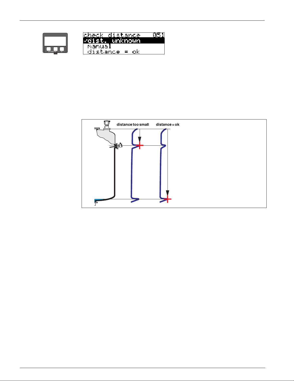
E
This function triggers the mapping of interference echoes. To do so, the measured
distance must be compared with the actual distance to the product surface. The
following options are available for selection:
Selection:
•distance = ok
• dist. too small
• dist. too big
• dist. unknown
• manual
distance = ok
• mapping is carried out up to the currently measured echo
• The range to be suppressed is suggested in the "range of mapping (052)" function
Anyway, it is wise to carry out a mapping even in this case.
dist. too small
• At the moment, an interference is being evaluated
• Therefore, a mapping is carried out including the presently measured echoes
• The range to be suppressed is suggested in the "range of mapping (052)" function
dist. too big
• This error cannot be remedied by interference echo mapping
• Check the application parameters (002), (003), (004) and "empty calibr." (005)
dist. unknown
If the actual distance is not known, no mapping can be carried out.
manual
A mapping is also possible by manual entry of the range to be suppressed. This entry is
made in the "range of mapping (052)" function.
Caution!
The range of mapping must end 0.5 m (20") before the echo of the actual level. For an
empty tank, do not enter E, but E – 0.5 m (20").
L00-FMR2xxxx-14-00-06-en-010
54 Installation and Operations Manual
Page 55
7532 Commissioning
Function "range of mapping" (052)
⇒
–
+
E
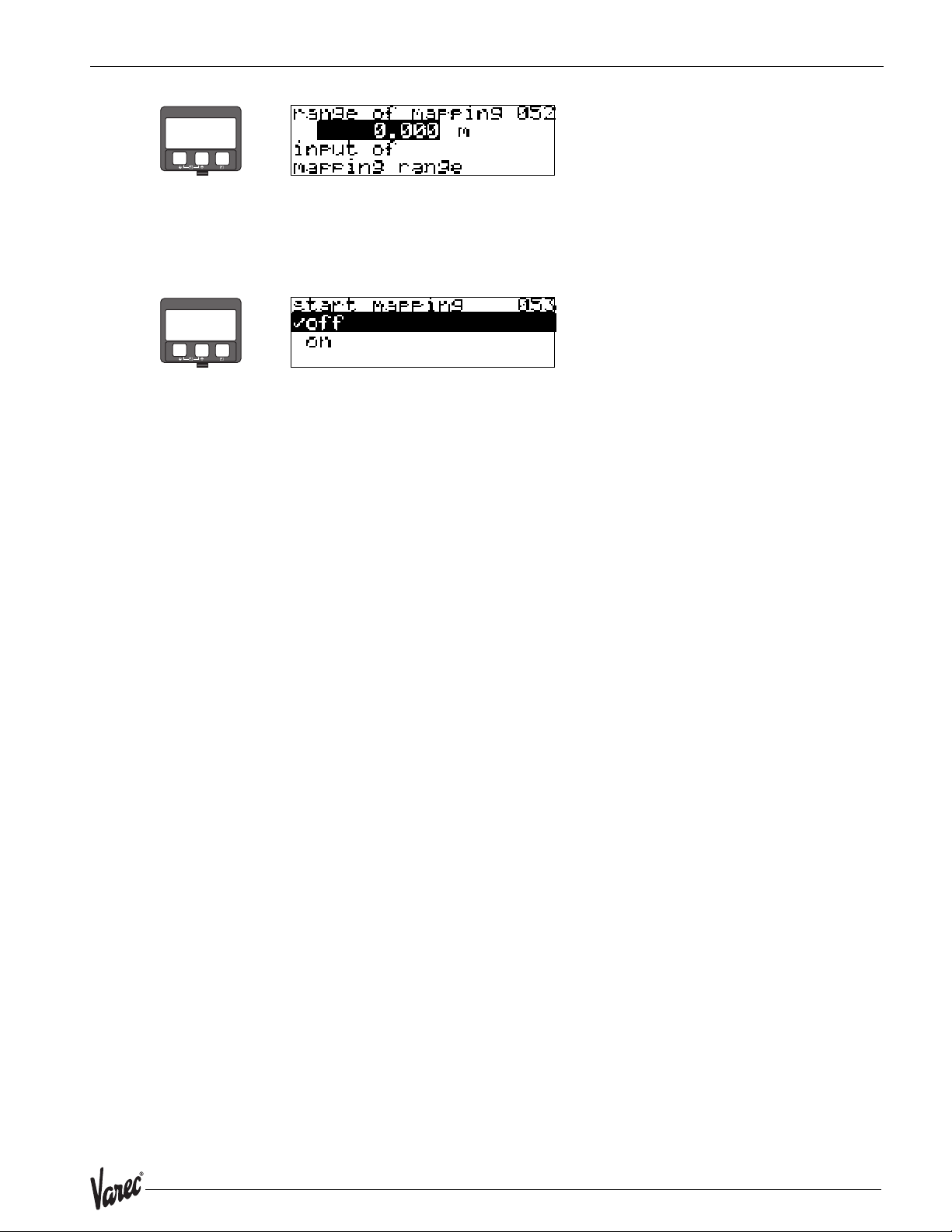
This function displays the suggested range of mapping. The reference point is always
the reference point of the measurement (see page 46). This value can be edited by the
operator.
For manual mapping, the default value is: 0 m.
Function "start mapping" (053)
⇒
–
+
E
This function is used to start the interference echo mapping up to the distance given in
"range of mapping" (052).
Selection:
• off: no mapping is carried out
• on: mapping is started
55
Page 56
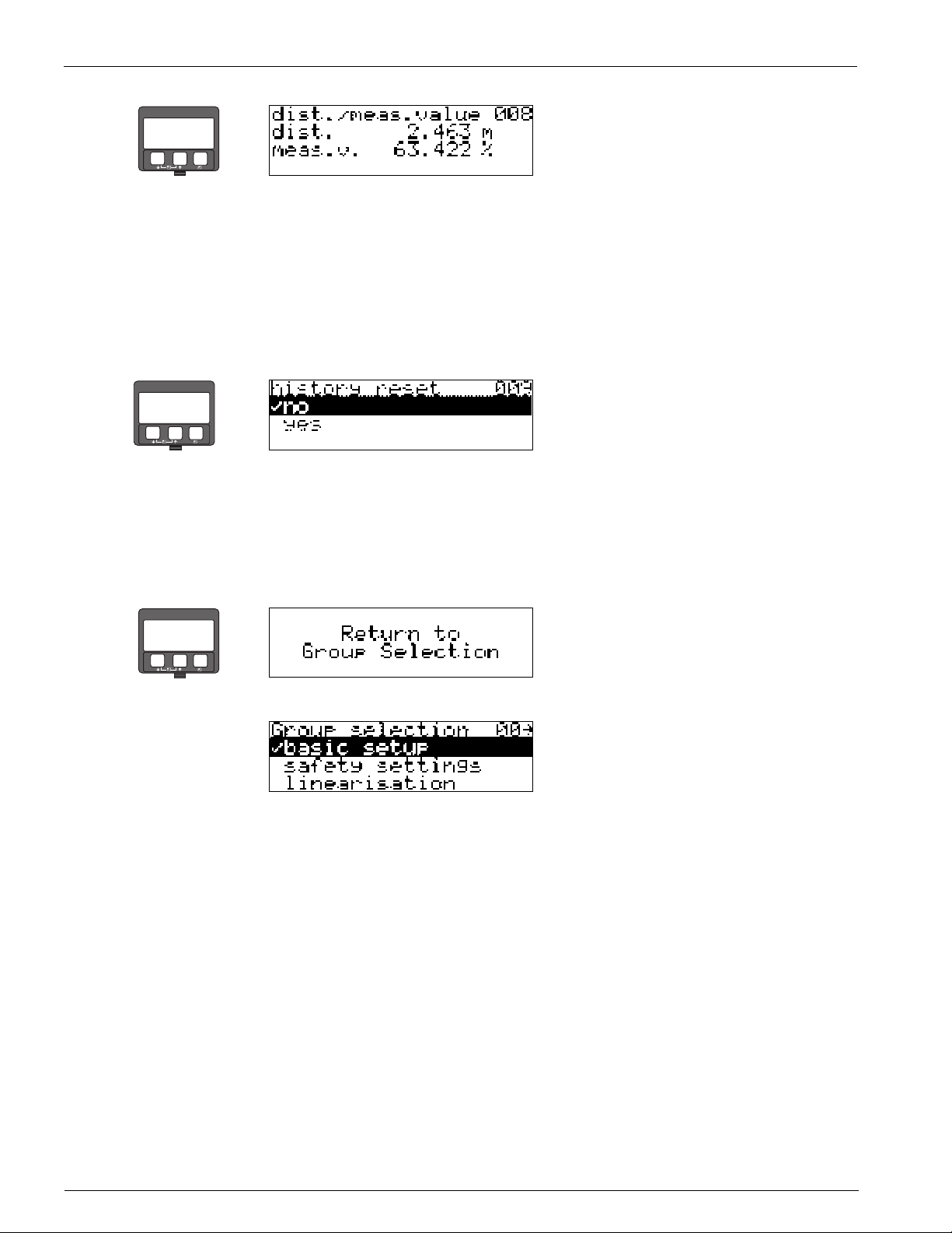
Commissioning Radar Tank Gauge
Display "dist./meas.value (008)"
⇒
–
+
E
The distance measured from the reference point to the product surface and the level
calculated with the aid of the empty alignment are displayed again. Check whether the
values correspond to the actual level or the actual distance. The following cases can
occur:
• Distance correct – level correct -> basic setup completed
• Distance incorrect – level incorrect -> a further interference echo mapping must be
carried out "check distance"(051).
• Distance correct – level incorrect -> check "empty calibr." (005)
Function "history reset" (009)
⇒
–
+
E
By this function a history reset of the device is performed, i.e. the correspondence table
between level an index values is deleted. A new correspondence table will be filled and
stored after the history reset, see page 57.
Caution!
Perform only after first installation (see »Function "auto-correction" (031)« on page 57).
In this case also effect a reset of the dip table in function "dip table mode" (033).
⇒
–
+
E
After 3 s, the following message appears
⇓
Note!
After basic calibration, it is wise to evaluate the measurement using the envelope curve
(function group "display" (09)).
56 Installation and Operations Manual
Page 57
7532 Commissioning
6.5 Mounting calibration with VU 331
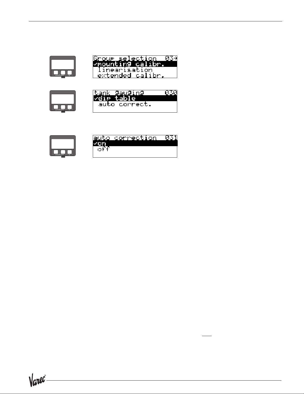
6.5.1 Function group "mounting calibr." (03)
⇒
–
+
E
Function "tank gauging" (030)
⇒
–
+
E
Using this function, you can either enter a dip table or carry out an auto-correction.
Function "auto-correction" (031)
⇒
–
+
E
"
When measuring levels with radar systems, so-called "multipath reflections" can affect
the level signal giving rise to serious measuring errors. "Multipath reflections" also
include radar beams which are received by the radar system, which have not been
reflected directly by the medium surface. They may reach the antenna via the basin wall
and the medium surface. This phenomenon is particularly noticeable with devices
mounted near to walls, as soon as the conical radar beam strikes the basin wall.
The 7500 RTG can automatically discover and correct measuring errors due to this
"multiple path" propagation. This is because it uses two independent sets of information
when evaluating reflection signals:
• Firstly, it evaluates the amplitude of the reflected energy using the so-called envelope
curve system.
• Secondly, it evaluates the phase of the reflected energy.
The decisive factor for a constant output signal is to assign the phase values to the
associated level values. This assignment is ensured using a correspondence table (index
correction table). The 7500 RTG learns this for the specific application after installation
(learning period).
Therefore, after mounting the device, and after completing the basic calibration, a
history reset must be performed (enter "yes" in the "history reset" (009) function in the
"basic setup " (00) function group).
Do not switch off the radar system during filling and emptying operations during the
teach-in phase. Switching off when there are only negligible level changes produces no
error.
Caution!
During the learning period, fast filling/emptying or turbulent surfaces can result in
switching off and on the phase evaluation. Subsequently observed measurement errors
will disappear as soon as tank levels come back to areas measured by 7500 RTG
previously with activated phase evaluation. If the observed measurement errors are
curetted by dip table entries, the 7500 RTG will take care of these corrections and
automatically adjust the index correction table. Do NOT
calibration or the extended calibration.
correct any settings in the basic
Note!
Immediately after installation, the 7500 RTG measures with the specified mm-accuracy.
Until the level range has been completely covered by the medium (setting up the
57
Page 58
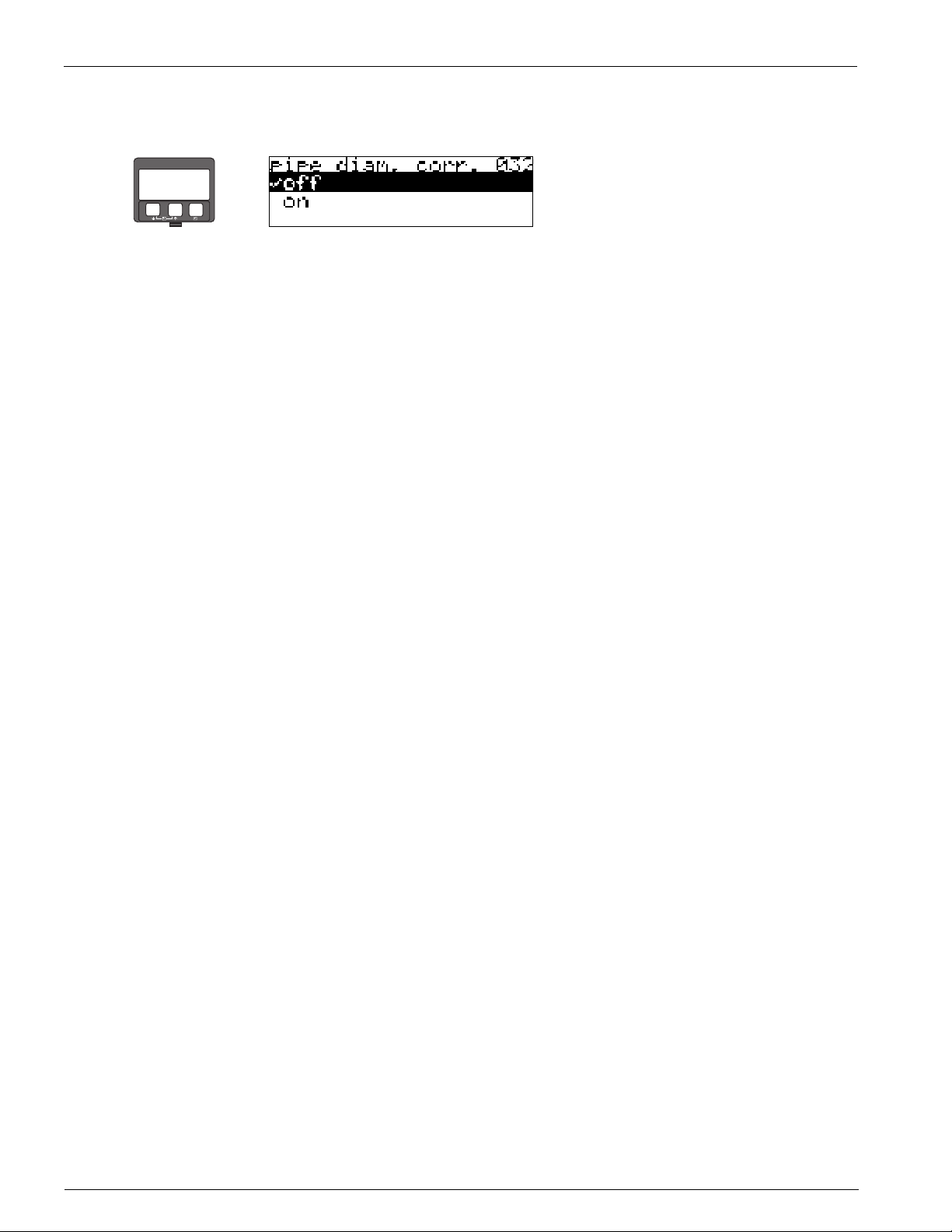
Commissioning Radar Tank Gauge
correction table), the maximum permissible filling speed is 100 mm level
change / min. After this, the fill speed has no limitation.
Function "pipe diam. corr." (032)
⇒
–
+
E
For level measurement in stilling wells, radar systems require highly precise pipe inner
diameter data. An mm-exact level measurement cannot be guaranteed for deviations
from the actual stilling well inner diameter of more than ± 0.1mm to the value entered
in the function group "basic setup" (00). The errors which occur as a result are linear and
can be corrected with a dip table containing at least two entries.
The 7500 RTG also has an automatic pipe inner diameter correction. This adjusts the
entered stilling well inner diameter (input in the function group
"basic setup" (00)) to the actual values. However, this presupposes that the value entered
in the function group "basic setup" (00) matches the actual pipe inner diameter
accurately as possible. The user-defined value entered in the function group
"basic setup" (00) can be c o rrec t e d wit h t h is v a l u e. In o r der t o d o thi s , s wit c h o n the "pipe
diam. corr." (032) function, after a level change of at least 5 m has occurred since startup. The pipe diameter, which the instrument determines automatically, will then be
transmitted to the "pipe diameter" (007) function.
Note!
Only if the "pipe diameter" (007) function has changed its value, it is necessary to perform a "history reset" (009) and to delete the dip table after activation of the "pipe diam.
corr." (032) function. Otherwise the level change of 5 m has not yet been exceeded. The
"pipe diam. corr." (032) function must be deactivated again and the procedure should be
repeated at a later point of time.
58 Installation and Operations Manual
Page 59
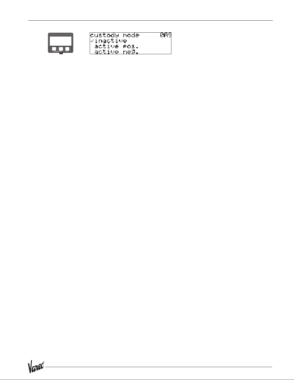
7532 Commissioning
Display "custody mode" (0A9)
⇒
–
+
E
This indicates the instrument calibration mode. The calibration mode (active) can be set
using the hardware security lock on the electronics (see Page 34).
Selection:
• inactive
•active pos.
•active neg.
active pos.
The custody mode (instrument is lead-sealed and accurate to the nearest mm) is active
and is held.
active neg.
Custody mode (instrument is lead-sealed and accurate to the nearest mm) is activated
and not held, e.g. because the signal-to-noise ratio is less than 10 dB (refer to
function "echo quality" (056) in the function group "extended calibr." (05)).
Caution!
After entering all the values and completing mounting and aligning work, enter the
Reset Code "555" in the function "history reset" (009) of the "basic setup" (00) function
group to reset the instrument history for auto-correction.
59
Page 60
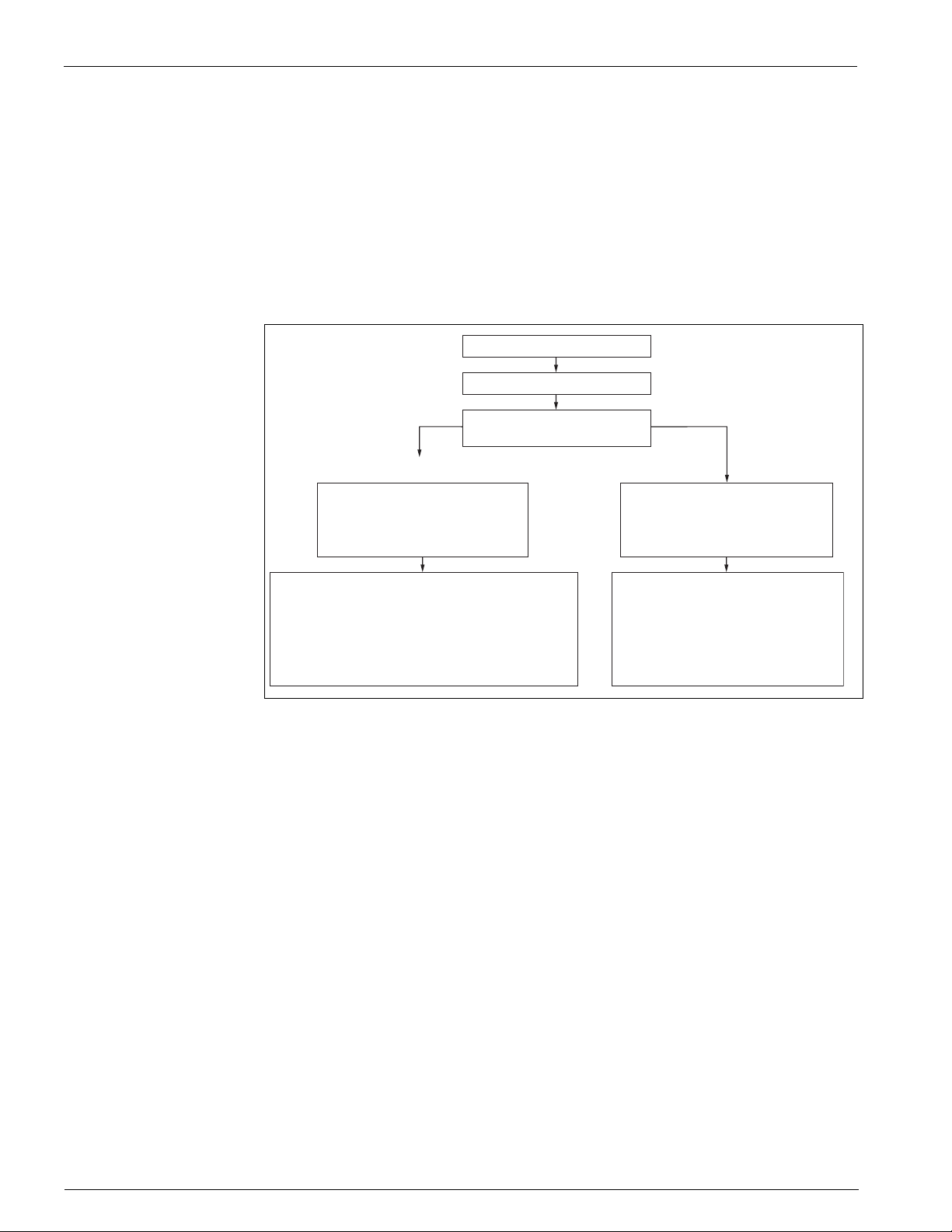
Commissioning Radar Tank Gauge
Dip table
The dip table is used to correct the level readings of the 7500 RTG using independently
taken hand dips. The dip table is used in particular to adapt the level gauge to the
specific application conditions as mechanical offset and tank/stilling well design.
Depending on national regulations, national inspectors will dip the tank at one to three
levels during a calibration run and check the level readings.
Only one value pair must be entered into the dip table to correct the measurement
offset.
If a second value pair is entered into the dip table, the 7500 RTG accepts the corrected
measured values identically for both value pairs. All other measured values are
determined by linear extrapolation.
If you enter more than two value pairs, the system carries out a linear interpolation
between adjacent value pairs. Outside these value pairs, extrapolation is also linear.
basic setup
history reset
dip table
alternatives
preferred choice:
hand dip
immediate
offset
semi-automatic
and
correction in
mode
collect hand dip and
measurement data over
full measurement range
collect further hand dip data;
if deviation from measurements
> 4 mm and level change > 2 m:
enter a new dip value
into dip table using the
evaluate collected data;
enter characteristic value
pairs into the dip table
using the manual mode
modesemi-automatic
Figure 8: Alternative procedures to fill the dip table.
To collect and enter data into the dip table, two alternative procedures may be carried
out. In order not to mix up measurement values corrected by the offset or linearization
of the dip table with uncorrected measurement values, it is recommended to use the
semi-automatic mode of the dip table to enter new data pairs. In this case, the first dip
value should be entered immediately after the basic calibration. Further linearization
points should be entered only after a level change of at least 2 m (see Figure 8:,
preferred choice) and a deviation between the "uncorrected measurement value" and the
hand dip value of at least 4mm.
If this procedure can not be followed, then NO value pair should be entered into the dip
table after basic calibration. Measurement data and hand dip values should be collected
over the full measurement range and be evaluated with regard to a good linear fit. Only
then characteristic value pairs should be entered into the dip table using the "manual
mode" (see Figure 8:, right side). If further linearization is needed, further hand dip
values should be entered using only the "semi-automatic mode".
L00-FMR53xxx-19-00-00-en-014
Note!
The offset should NOT be determined and entered within the close range of the antenna
(conf. definition of the safety distance) or immediately in the range of the tank bottom,
because within these ranges interferences of the radar signal may occur.
60 Installation and Operations Manual
Page 61
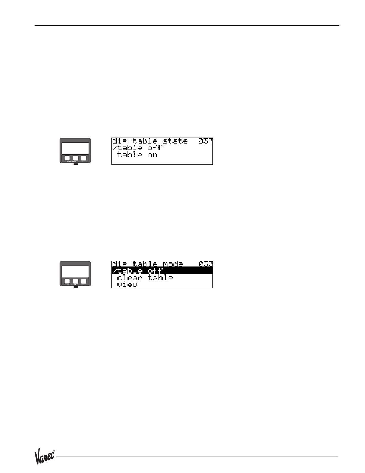
7532 Commissioning
Note!
The dip table can be printed out using the ToF-Tool. Before doing this, the ToF Tool
must be reconnected to the instrument in order to update the values within the ToF Tool.
Note!
Make your inputs into the dip table in semi-automatic mode. We advise you to leave
"auto correction" (031) activated ("on") while you enter your inputs.
Caution!
After entering one or more points into the dip table, make sure that the dip table is
activated and left in the "table on" dip table mode.
Function "dip table state" (037)
⇒
–
+
E
This function displays the dip table status.
Display:
•table on
• table off
table on
Indicates whether the dip table is active.
table off
Indicates whether the dip table is not active.
Function "dip table mode" (033)
⇒
–
+
E
The dip table can be switched on or off using this function.
Selection:
• manual
• semi-automatic
•table on
• table off
•clear table
•view
61
Page 62
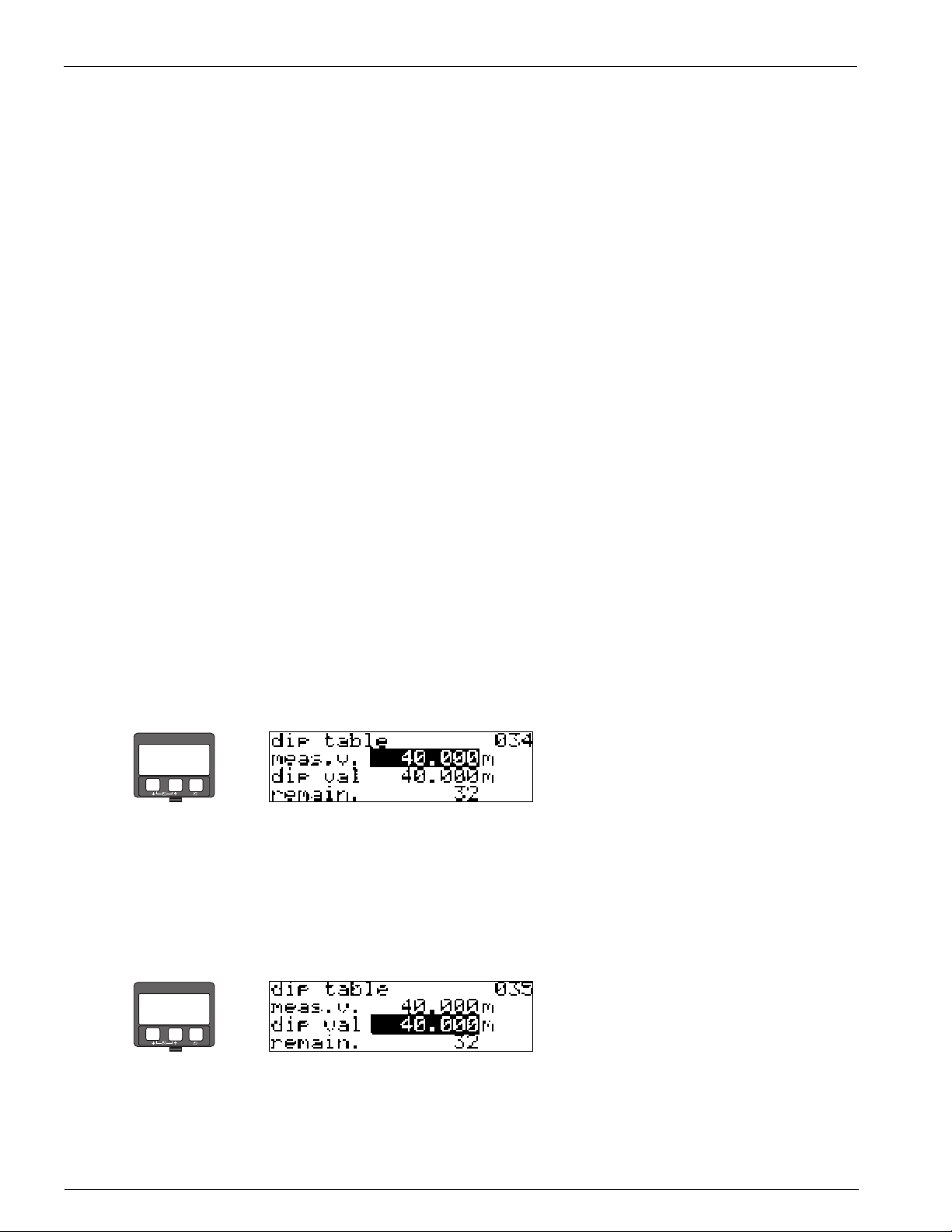
Commissioning Radar Tank Gauge
manual
The value pairs in the dip table can be read and written. You can enter the measured
value and the dip value.
–uncorrected measured value:
This is the measured value supplied by the instrument, NOT corrected by the dip
table. The choice of measured value, level or remaining fill height is dependent on
the instrument setting.
–Dip value:
This is the level or distance to flange respectively, given by the hand dip. This value
should be used to correct the measured value.
The "manual mode" of the dip table can be used to enter collected data after a series
of data pairs taken at different tank levels.
Note!
The bigger the distance between the different levels while taking hand dips, the more
accurate the linearization of the dip table will be.
semi-automatic
The value pairs in the dip table can be read. You can enter the dip value only. When there
are new value pairs, the current level or distance is accepted as the measured value.
table on
The dip table is switched on.
table off
The dip table is switched off.
clear table
The complete dip table is deleted. The table is switched off. The number of free table
entries is set to the maximum value (=32).
View
The value pairs in the dip table can only be read. You can still select this menu option,
even if there is no dip table available. In this case, the number of free table entries is at
maximum value (=32).
Function "dip table" (034)
⇒
–
+
E
This function edits measured variable. The number behind the entry "remain" indicates
the current number of remaining free value pairs. The maximum number of value pairs
is 32; after each entry, the remaining number is decremented.
Note!
The uncorrected measured value is displayed in the "dip table" (034) function. This may
differ considerably from the measured values when a dip table is activated.
Function "dip table" (035)
⇒
–
+
E
This function edits the dip value.
62 Installation and Operations Manual
Page 63
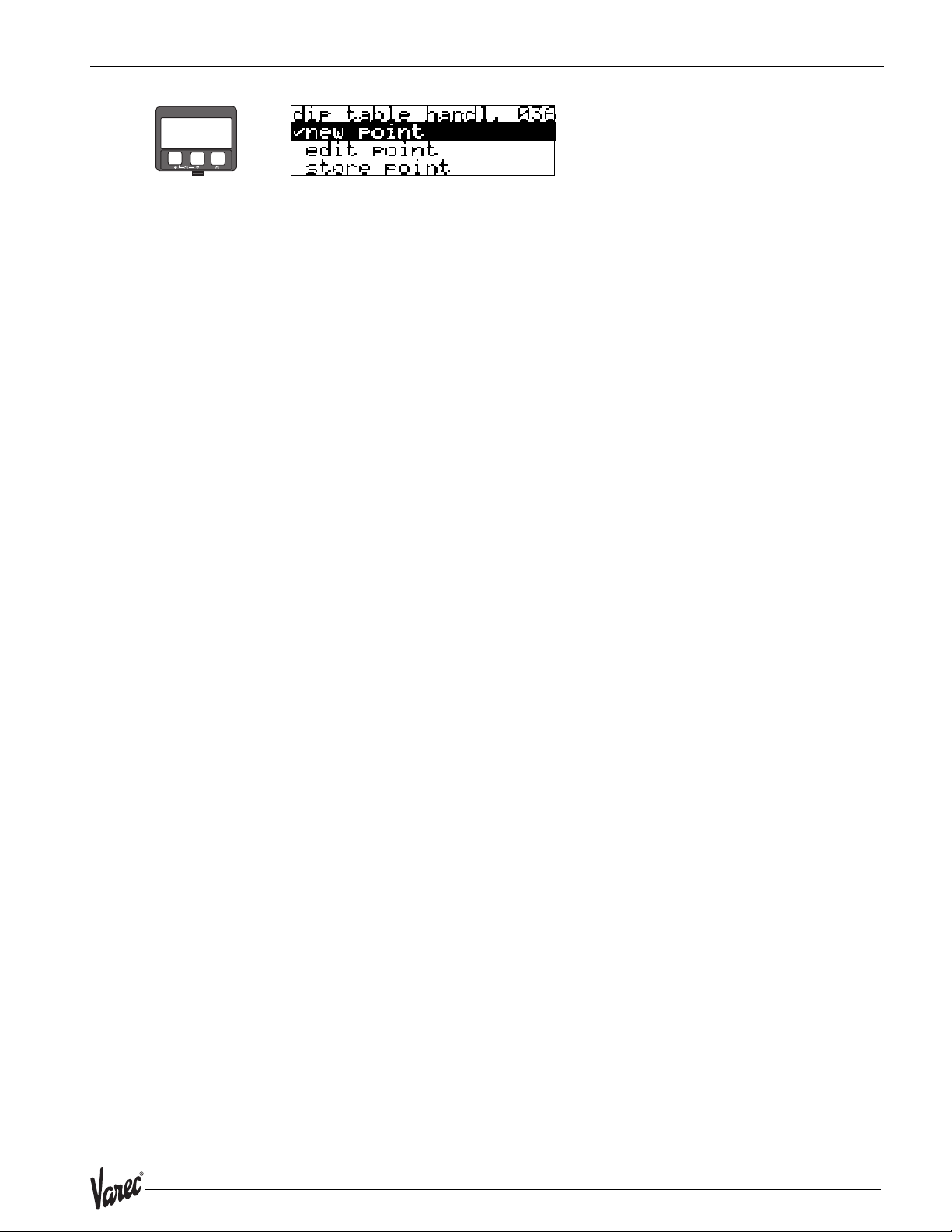
7532 Commissioning
Function "dip table handl." (036)
⇒
–
+
E
Use this function to enter the dip value (level or distance) which will correct the measurement values.
Selection:
• new point
• edit point
•store point
• delete point
•return
•next point
•previous point
General procedure:
To enter a new point into the dip table, use
"new point" to enter the value (pairs),
"store point" to sort the new value (pairs),
"return" to go to the dip table mode and
"table on" to activate the dip table.
new point
You can enter a new point. A suggested value is displayed for the measured variable, the
dip value of the current level or the distance. With semi-automatic inputs, the current
level or the current remaining fill height is displayed as proposed dip value. The new
value pair can be altered without selecting the
"edit point" parameter.
If the table is full, you can still select this parameter. In this case, the number of free
table entries stands at minimum value (=0).
edit point
The displayed value pair can be changed. Only the dip value can be changed with semiautomatic input mode.
Caution!
To accept the value pair in the table, confirm it with "store point".
store point
The displayed value pair is sorted in the table.
Note!
For sorting, the following criteria must be met:
• Measured variables may not be equal but have different dip values.
• A measured variable available in the table is recognized as equal when it is closer than
1 mm to the sorting value.
• After successful sorting, the setting remains at "edit point" and the number of free
table entries is decremented.
Caution!
If the value cannot be sorted, the setting remains at the previous menu option. No
warning or error message is generated. However, the number of remaining table entries
is not decremented.
63
Page 64

Commissioning Radar Tank Gauge
delete point
The currently displayed point is deleted from the table. After deletion, the previous point
is displayed. If the table only consisted of one point before deletion, then the current
measured variable is displayed as a value pair.
return
By selecting this point, you return to the function "dip table mode" (033).
next point
This scrolls down in the table. If the table is empty, you can still select this option.
However, the displayed value does not change.
previous point
This scrolls up in the table. If the table is empty, you can still select this option. However,
the displayed value does not change.
Caution!
After entering one or more points into the dip table, make sure that the dip table is
activated in the "table on" dip table mode.
64 Installation and Operations Manual
Page 65
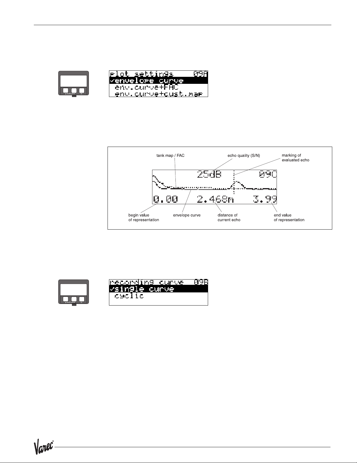
7532 Commissioning
6.5.2 Envelope curve with VU 331
After the basic setup, an evaluation of the measurement with the aid of the envelope
curve ("display" (09) function group) is recommended.
Function "plot settings" (09A)
⇒
–
+
E
Here you can select which information is shown on the display:
• envelope curve
• env. curve+FAC (for FAC see
instrument functions
• env. curve+suppress. (i.e. the tank map is also displayed)
")
7500 RTG "Service manual and description of
L00-FMRxxxxx-07-00-00-en-004
Function "recording curve" (09B)
This function determines whether the envelope curve is read as:
• single curve
or
• cyclic
⇒
–
+
E
Note!
If the envelope curve mode is active on the display, the measured values are updated in
a slower cycle time. Thus, it is advisable to leave the envelope curve mode after the
measuring point has been optimized.
65
Page 66
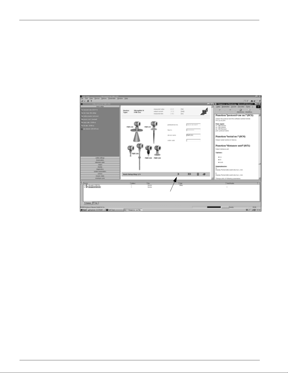
Commissioning Radar Tank Gauge
6.6 Basic Setup with the ToF Tool
To carry out the basic setup with the ToF Tool operating program, proceed as follows:
• Start the ToF Tool operating program and establish a connection
• Select the "basic setup" function group in the navigation bar
The following display appears on the screen:
Basic Setup step 1/5:
•Status image
• Enter the measuring point description (TAG number).
Change to the next page
Note!
• Each parameter that is changed must be confirmed with the RETURN key!
•The "Next" button moves you to the next screen display:
66 Installation and Operations Manual
Page 67
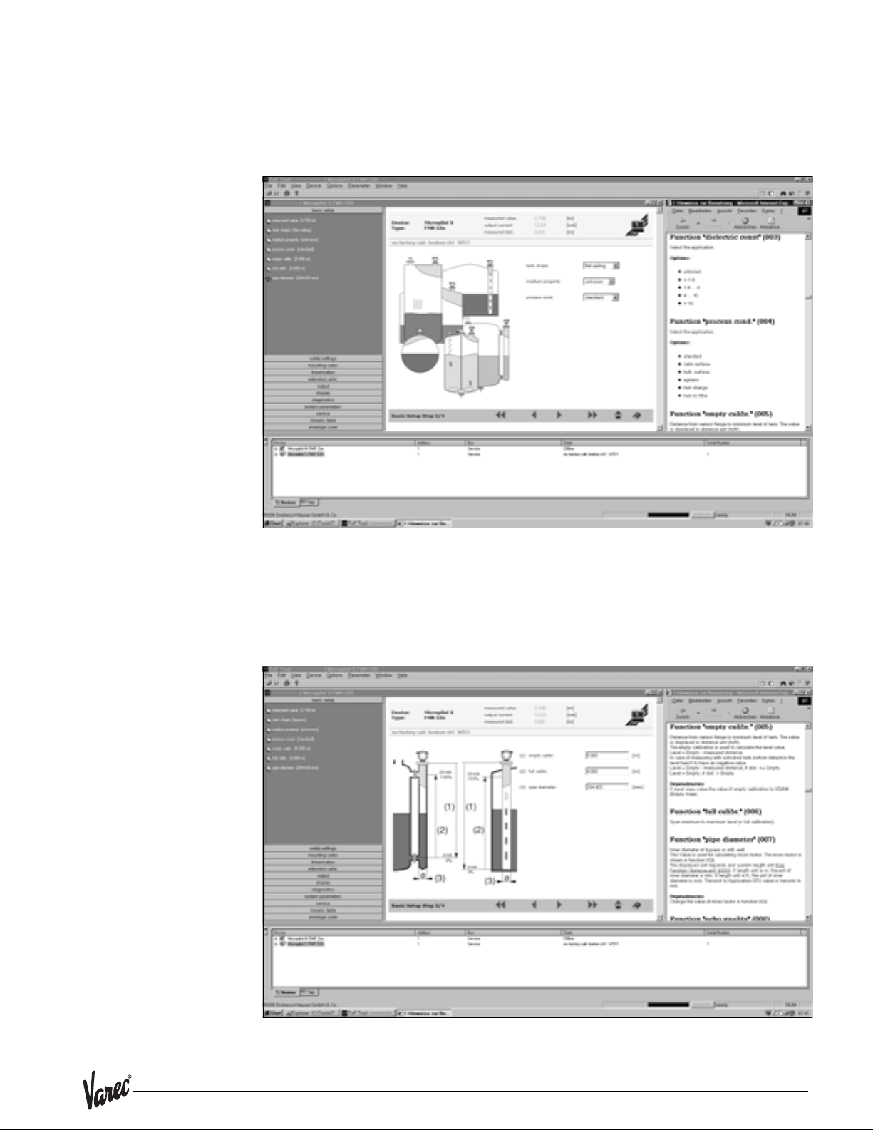
7532 Commissioning
Basic Setup step 2/5:
• Enter the application parameters:
–tank shape (for a description, see page 49)
–medium property (for a description, see page 50)
–process cond. (for a description, see page 51)
Basic Setup step 3/5:
If "stilling well" or "bypass" is selected in the "tank shape" function, the following display
appears on the screen:
• empty calibr. (for a description, see page 52)
• full calibr. (for a description, see page 52)
• Diameter of bypass / stilling well (for a description, see page 53)
67
Page 68
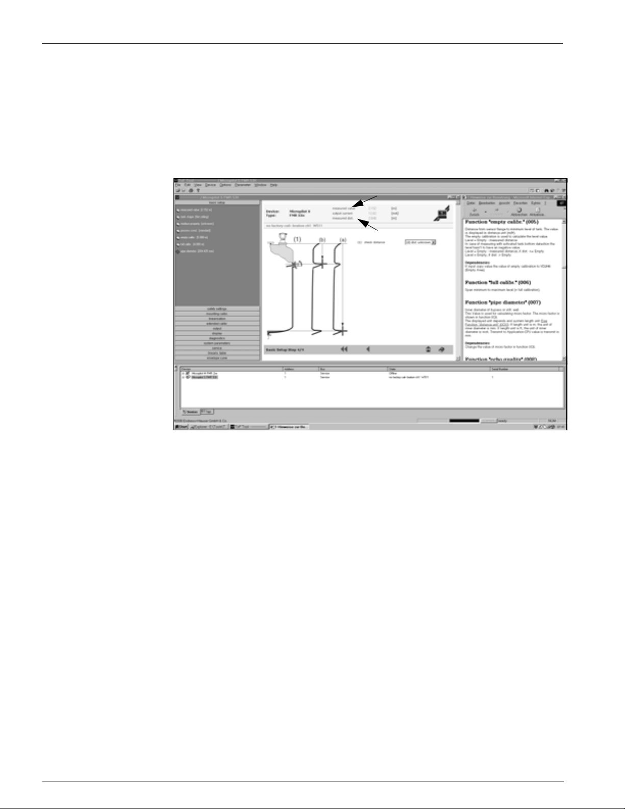
Commissioning Radar Tank Gauge
Note!
You can also specify the pipe diameter in this display.
Basic Setup step 4/5:
• This step starts the tank mapping
• The measured distance and the current measured value are always displayed in the
header
• A description is given on page 56
measured value
distance
Step 5/5:
After the first installation of the device, initialise the index correction table (compare
page 57) by activating the history reset 555.
68 Installation and Operations Manual
Page 69
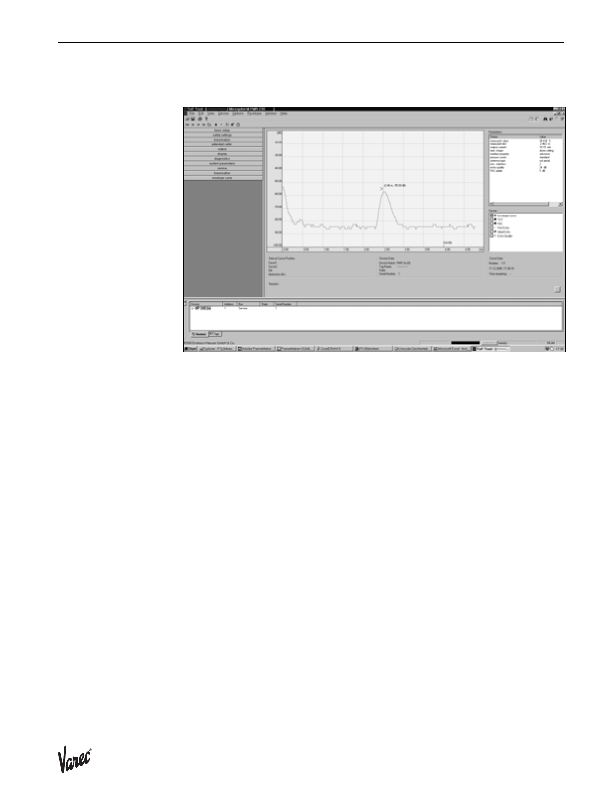
7532 Commissioning
6.6.1 Envelope curve with the ToF Tool
After the basic setup, an evaluation of the measurement using the envelope curve is
recommended.
6.6.2 User-specific applications (operation)
To set the parameters of user-specific applications, see the 7500 RTG "Service manual
and description of instrument functions".
69
Page 70
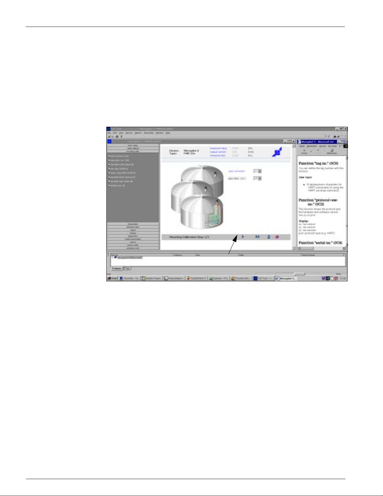
Commissioning Radar Tank Gauge
6.7 Mounting calibration with the ToF Tool
To carry out the basic setup with the ToF Tool operating program, proceed as follows:
• Start the ToF Tool operating program and establish a connection
• Select the "mounting calibr." function group in the navigation bar
The following display appears on the screen:
Mounting calibration step 1/2:
• auto correction (description see page 57)
• pipe diam. corr. (description see page 58)
change to next page
Note!
• Each parameter that is changed must be confirmed with the RETURN key!
•the "Next" button moves you to the next screen display:
70 Installation and Operations Manual
Page 71
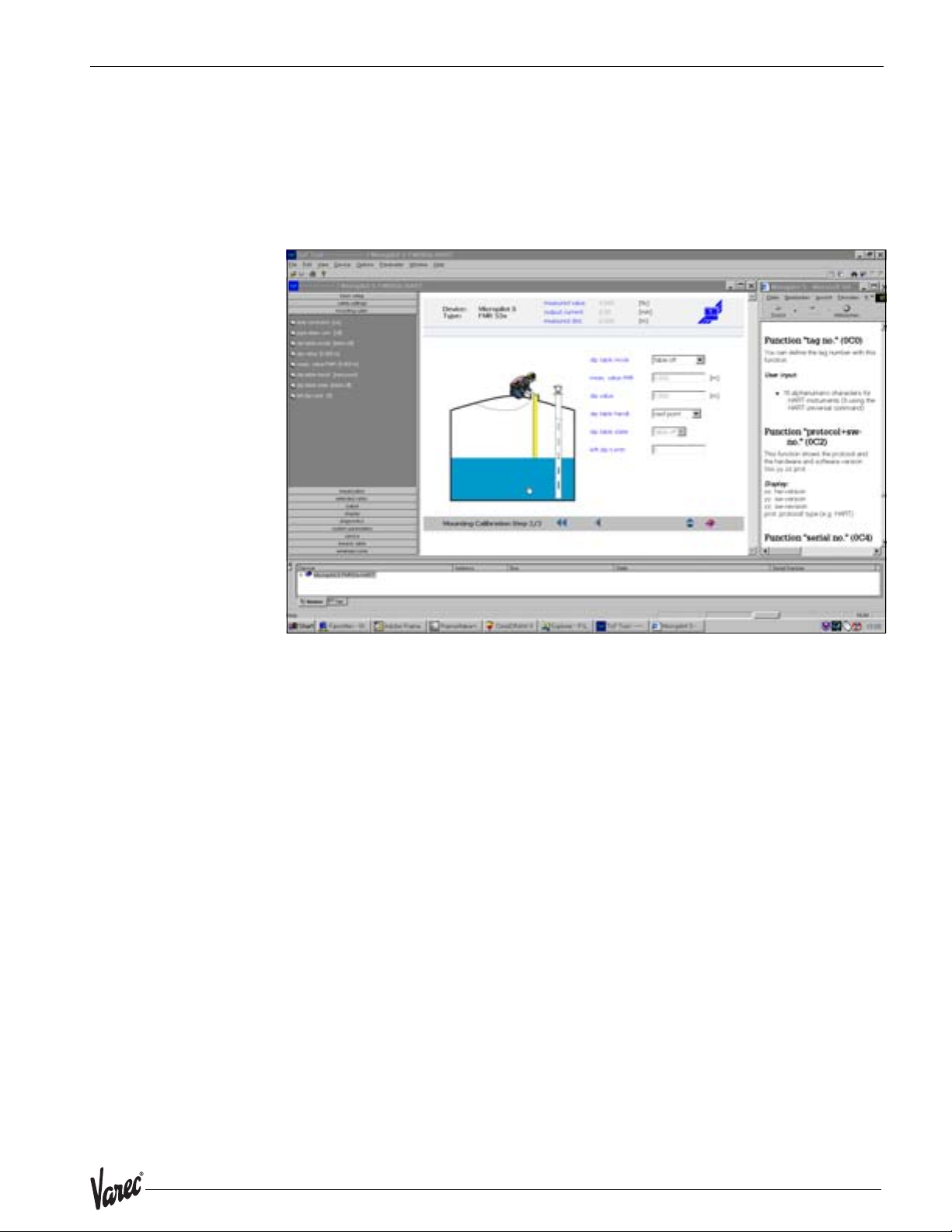
7532 Commissioning
Mounting calibration step 2/2:
• dip table mode (description see page 61)
• meas. v. (description see page 62)
•dip value (seepage62)
• dip table handl. (description see page 63)
• dip table state (description see page 61)
• left dip t.entr. (description seepage61)
71
Page 72

Commissioning Radar Tank Gauge
72 Installation and Operations Manual
Page 73

7532 Maintenance
7 Maintenance
The 7500 RTG measuring instrument requires no special maintenance.
Exterior cleaning
When cleaning the exterior of measuring devices, always use cleaning agents that do not
attack the surface of the housing and the seals.
Replacement
After a complete 7500 RTG or electronic module has been replaced, the parameters can
be downloaded into the instrument again via the communication interface. Prerequisite
to this is that the data were uploaded to the PC beforehand using the ToF Tool /
Commuwin II.
Measurement can continue without having to carry out a new setup.
• You may have to activate linearization
• You may need to record the tank map again
After an antenna component has been replaced, a new calibration must be carried out.
73
Page 74

Maintenance Radar Tank Gauge
74 Installation and Operations Manual
Page 75
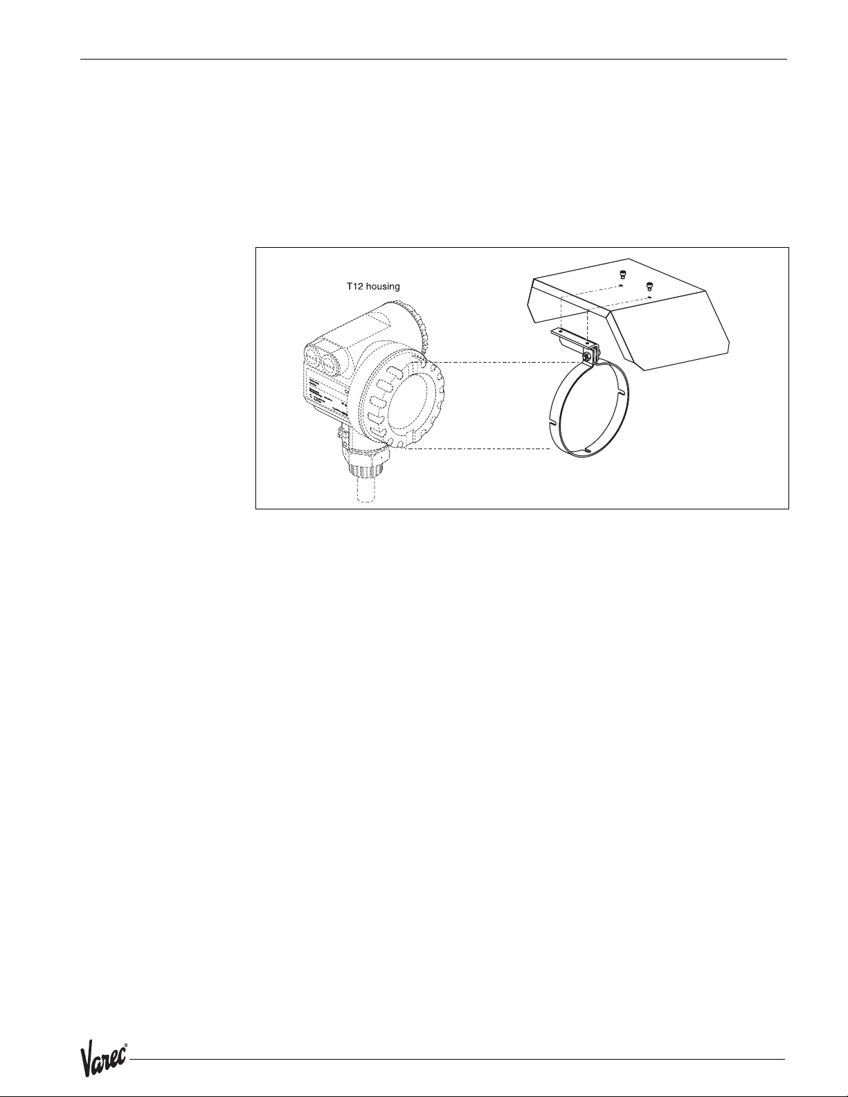
7532 Accessories
8 Accessories
Various accessories, which can be ordered separately from Varec, are available for the
7500 RTG.
Weather protection cover
A Weather protection cover made of stainless steel is available for outdoor mounting
(order code: 543199-0001). The shipment includes the protective cover and tension
clamp.
Commubox FXA 191 HART
For intrinsically safe communication with ToF Tool or Commuwin II via the RS 232Cinterface.
Service adapter FXA 193
For communication with ToF Tool via the display connector. (Bestell-Nr.: 50095566).
Commuwin II
Operating software for intelligent instruments.
L00-FMR53xxx-00-00-06-en-001
75
Page 76

Accessories Radar Tank Gauge
76 Installation and Operations Manual
Page 77

7532 Troubleshooting
9 Troubleshooting
9.1 Troubleshooting instructions
77
Page 78
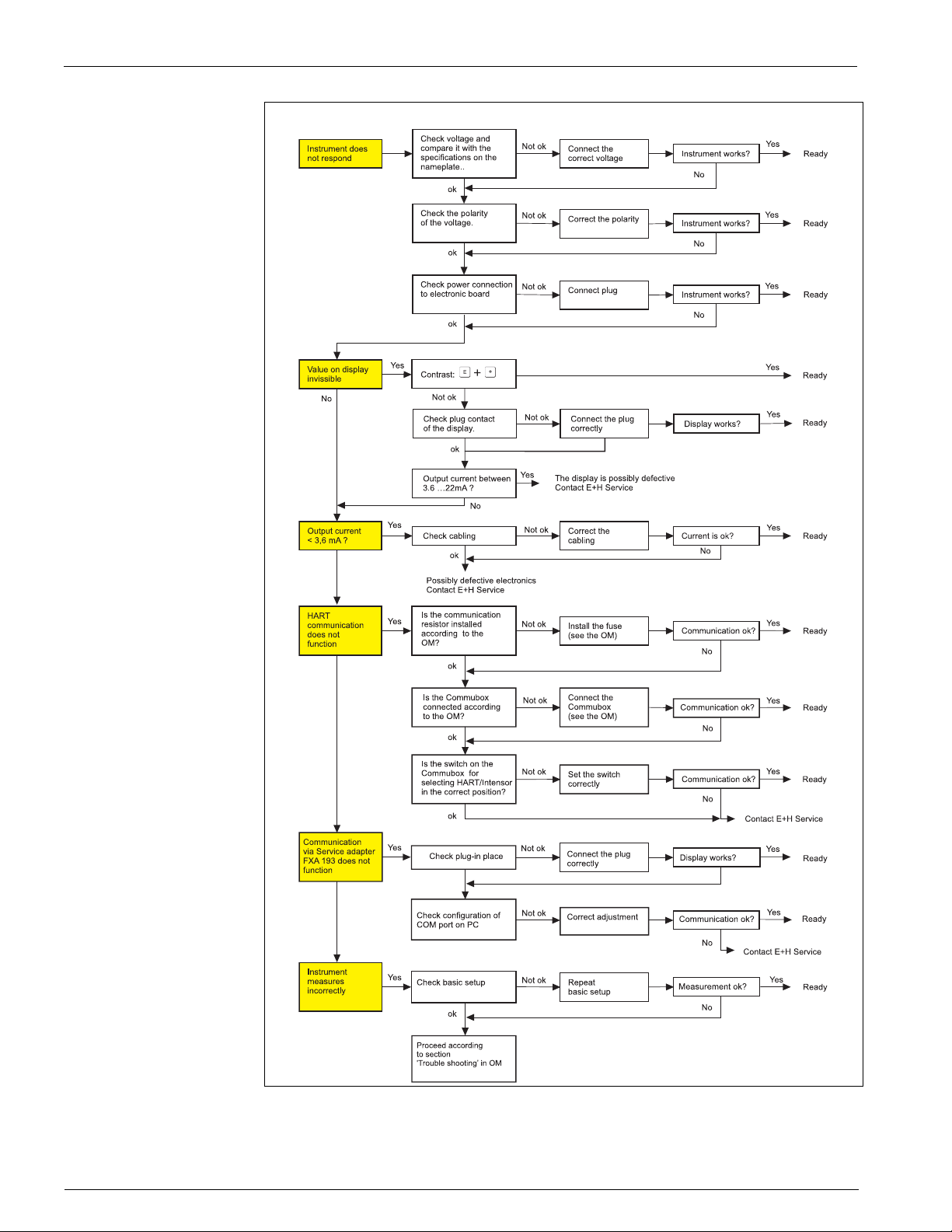
Troubleshooting Radar Tank Gauge
7500 RTG - Troubleshooting
78 Installation and Operations Manual
L00-FMR53xxx-19-00-00-en-010
Page 79
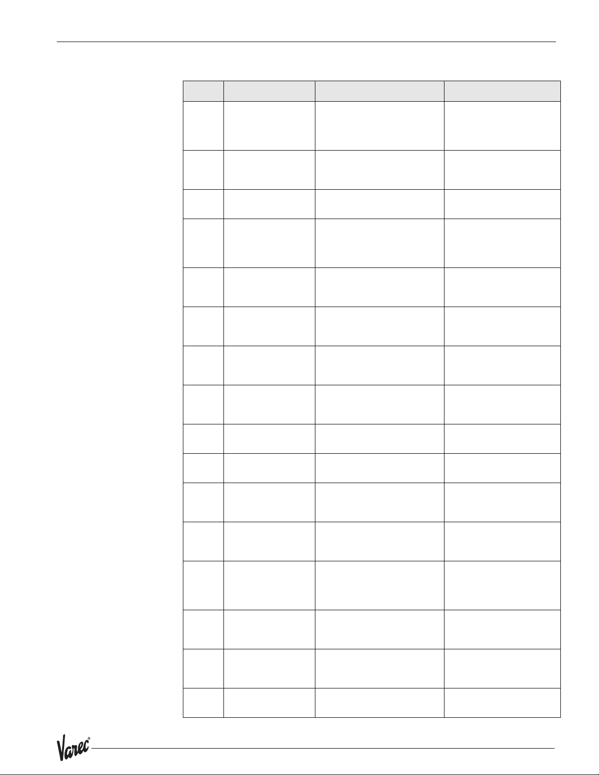
7532 Troubleshooting
9.2 System error messages
Code Description Possible cause Remedy
A102 checksum error
general reset & new
calibr.required
W103 initialising - please
wait
A106 downloading please
wait
A110 checksum error
general reset & new
calibr.required
A111 electronics defect RAM defective reset;
A113 electronics defect ROM defective reset;
A114 electronics defect E2PROM defective reset;
A115 electronics defect general hardware problem reset;
device has been powered off
before data could be stored;
emc problem; E²PROM defect
E²PROM storage not yet
finished
processing data download wait until warning
device has been powered off
before data could be stored;
emc problem; E²PROM defect
reset;
avoid emc problem; if
alarm prevails after reset,
exchange electronics
wait some seconds; if
warning prevails, exchange
electronics
disappears
reset;
avoid emc problem; if
alarm prevails after reset,
exchange electronics
if alarm prevails after
reset, exchange electronics
if alarm prevails after
reset, exchange electronics
if alarm prevails after
reset, exchange electronics
if alarm prevails after
reset, exchange electronics
A116 download error
repeat download
A121 electronics defect no factory calibration existant;
W153 initialising - please
wait
A155 electronics defect hardware problem reset;
A160 checksum error
general reset & new
calibr.required
A164 electronics defect hardware problem reset;
A171 electronics defect hardware problem reset;
A231 sensor 1 defect
check connection
checksum of stored data not
correct
E²PROM defective
initialisation of electronics wait some seconds; if
device has been powered off
before data could be stored;
emc problem; E²PROM defect
HF module or electronics
defective
restart download of data
contact service
warning prevails, power off
device and power on again
if alarm prevails after
reset, exchange electronics
reset;
avoid emc problem; if
alarm prevails after reset,
exchange electronics
if alarm prevails after
reset, exchange electronics
if alarm prevails after
reset, exchange electronics
exchange HF module or
electronics
Table 3: System error messages
79
Page 80
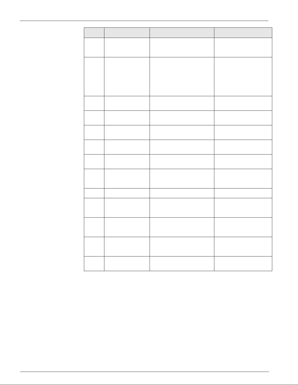
Troubleshooting Radar Tank Gauge
Code Description Possible cause Remedy
A270 custody switch
undef
check position
# inconsistency between phase
A272 electronics defect
amplifier
W275 electronics defect
factory setting
W511 no factory
calibration ch1
A512 recording of
mapping please wait
W601 linearization ch1
curve not monotone
W611 less than 2
linearization points
for channel 1
switch for custody transfer
may be defective
and amplitude evaluation
inconsistent microfactor
inconsistent index mapping
inconsistency in amplification exchange electronics
offset drift of A/D commuter exchange electronics
factory calibration has been
deleted
mapping active wait some seconds until
linearization not
monotonously increasing
number of entered
linearization points < 2
check position of custody
switch
exchange electronics
check basic calibration
check mounting calibration
check echo quality
reset history "555"
check stilling pipe
diameter
switch off autocorrection
record new factory
calibration
alarm disappears
correct linearization table
correct linearization table
W621 simulation ch. 1 on simulation mode is active switch off simulation mode
E641 no usable echo
channel 1
check calibr.
E651 level in safety
distance - risk of
overspill
A671 linearization ch1 not
complete, not
usable
W681 current ch1 out of
range
echo lost due to application
conditions of built up on
antenna
level in safety distance alarm will disappear as
linearization table is in edit
mode
current out of range (3,8 mA
... 21,5 mA)
check installation;
optimize orientation of
antenna; clean antenna
soon as level leaves safety
distance;
activate linearization table
check calibration and
linearization
Table 3: System error messages
80 Installation and Operations Manual
Page 81
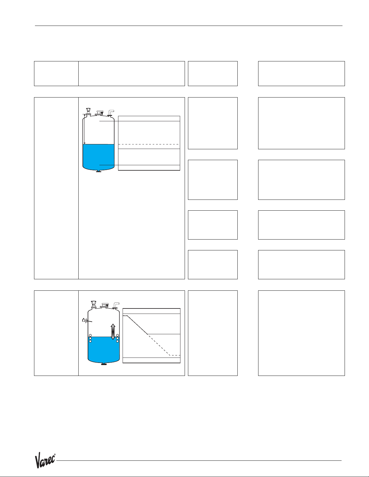
7532 Troubleshooting
9.3 Application errors
Error Output Possible cause Remedy
A warning or
alarm has
occurred.
Measured
value (00) is
incorrect
Depending on the configuration See table of
F m/ft
D m/ft (008)
E m/ft
20 mA/100%
expected
actual
4 mA/0% t
→
error messages
(see page 79)
Measured distance
(008) OK?
no ↓
Measurement in
bypass or stilling
well?
no
Is an
FAR 10 antenna
extension
being used?
1. See table of error messages
(see page 79)
yes → 1. Check empty calibr. (005) and
full calibr. (006).
2. Check linearization:
→ level/ullage (040)
→ max. scale (046)
→ diameter vessel (047)
→ Check table
yes
→ 1. Is bypass or stilling well
selected
in tank shape (002)?
2. Is the pipe diameter
(007) correct?
↓
yes
→ 1. offset (057)
correctly set?
No change off
measured
value on
filling/emptying
20 mA/100%
actual
expected
4 mA/0% t
An interference
echo
may have been
evaluated.
Interference echo
from
installations,
nozzle
or extension on
the
antenna
→
no
↓
yes
→ 1. Carry out tank mapping
→ basic setup
1. Carry out tank mapping
→ basic setup
2. If necessary, clean antenna
3. If necessary, select better
mounting position
81
Page 82
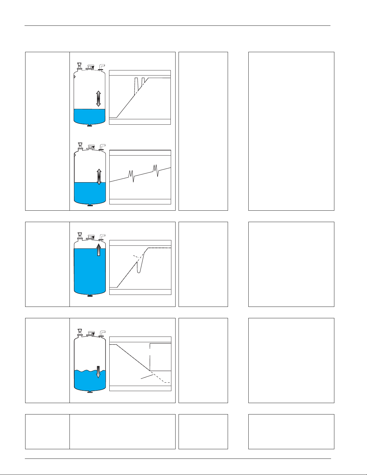
Troubleshooting Radar Tank Gauge
Error Output Possible cause Remedy
If the surface
is not calm
(e.g. filling,
emptying, agitator running), the
measured
value
jumps sporadically to a
higher
level
During filling/
emptying
the measured
value jumps
downwards
20 mA/100%
actual
expected
4 mA/0% t →
20 mA/100%
actual
expected
4 mA/0% t →
20 mA/100%
actual
expected
4 mA/0% t →
Signal is weakened
by the rough
surface — the
interference
echoes
are sometimes
stronger
Multiple echoes yes → 1. Check the tank shape (002),
1. Carry out tank mapping
→ basic setup
2. Set the process cond. (004) to
"turb. surface" or
"agitator"
3. Increase the output damping
(058)
4. Optimize the orientation
5. If necessary, select a better
mounting position
and/or larger antenna
e.g. "dome ceiling" or
"horizontal cyl"
2. In the range of the blocking dist.
(059) there is no echo evaluation
→ Adapt the value
3. If possible, do not select
central installation position
4. Perhaps use a stilling well
E 641 (loss of
echo)
E 641 (loss of
echo) after
turn on the
power supply
20 mA/100%
actual
E 641
expected
4 mA/0% t →
If the instrument is configured to Hold
by loss of echo the output is set to any
value/current.
Level echo is too
weak.
Possible causes:
•Rough surface
due to filling/
emptying
• Agitator running
•Foam
noise level during
the initialisation
phase to high.
yes
→ 1. Check application parameters
(002), (003) and (004)
2. Optimize alignment
3. If necessary, select a better
installation position and/or
larger antenna
Repeat once more empty calibr.
(005).
Caution!
Before conformation change with
O or S to the edit mode.
82 Installation and Operations Manual
Page 83

7532 Troubleshooting
9.4 Spare parts
Note!
You can order spare parts directly from your Varec service organization by giving the
order code and the serial number which is printed on the measuring transducer
nameplate (see page 7). The corresponding spare part number also appears on each
spare part. Installation instructions are given on the instruction card that is also
delivered.
Note!
If the calibration seal is broken, the national calibration authority should normally be
informed within 24 hours.
83
Page 84
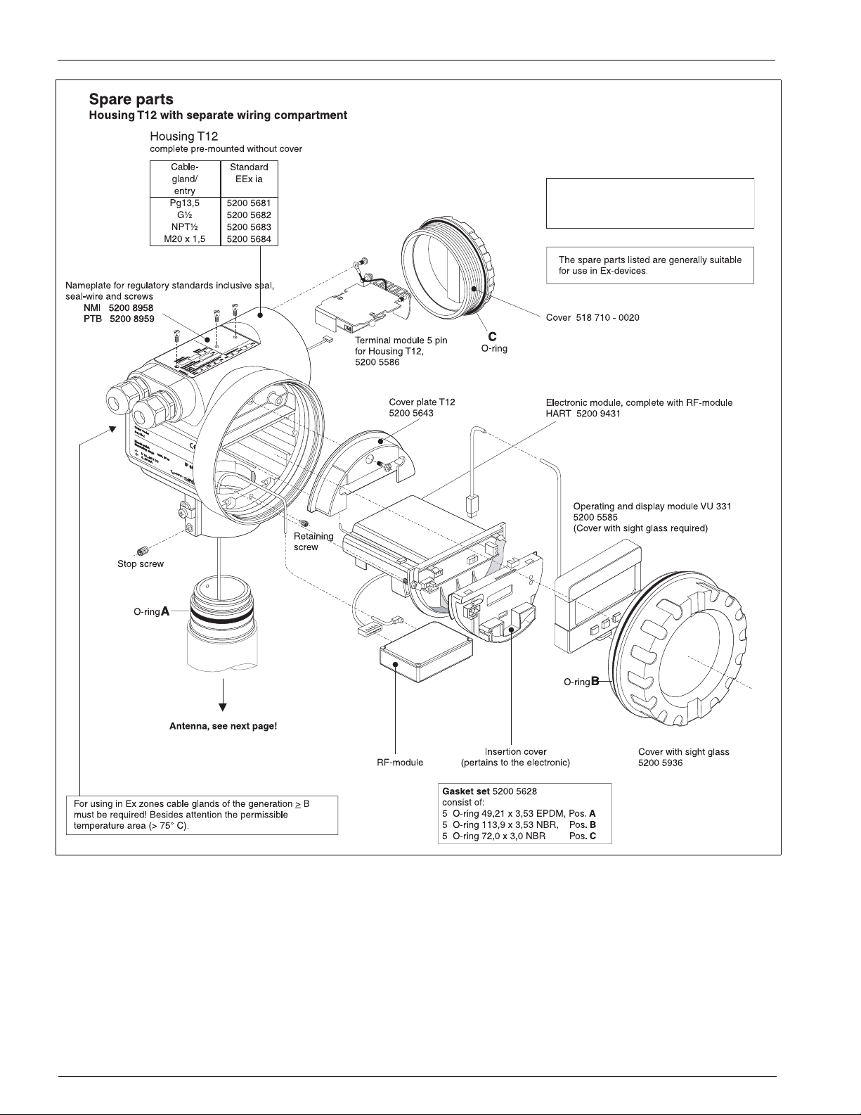
Troubleshooting Radar Tank Gauge
7532 RTG
The customer may exchange
modular assemblies in
accordance with Varec
instructions!
84 Installation and Operations Manual
L00-FMR532xx-00-00-06-en-001
Page 85
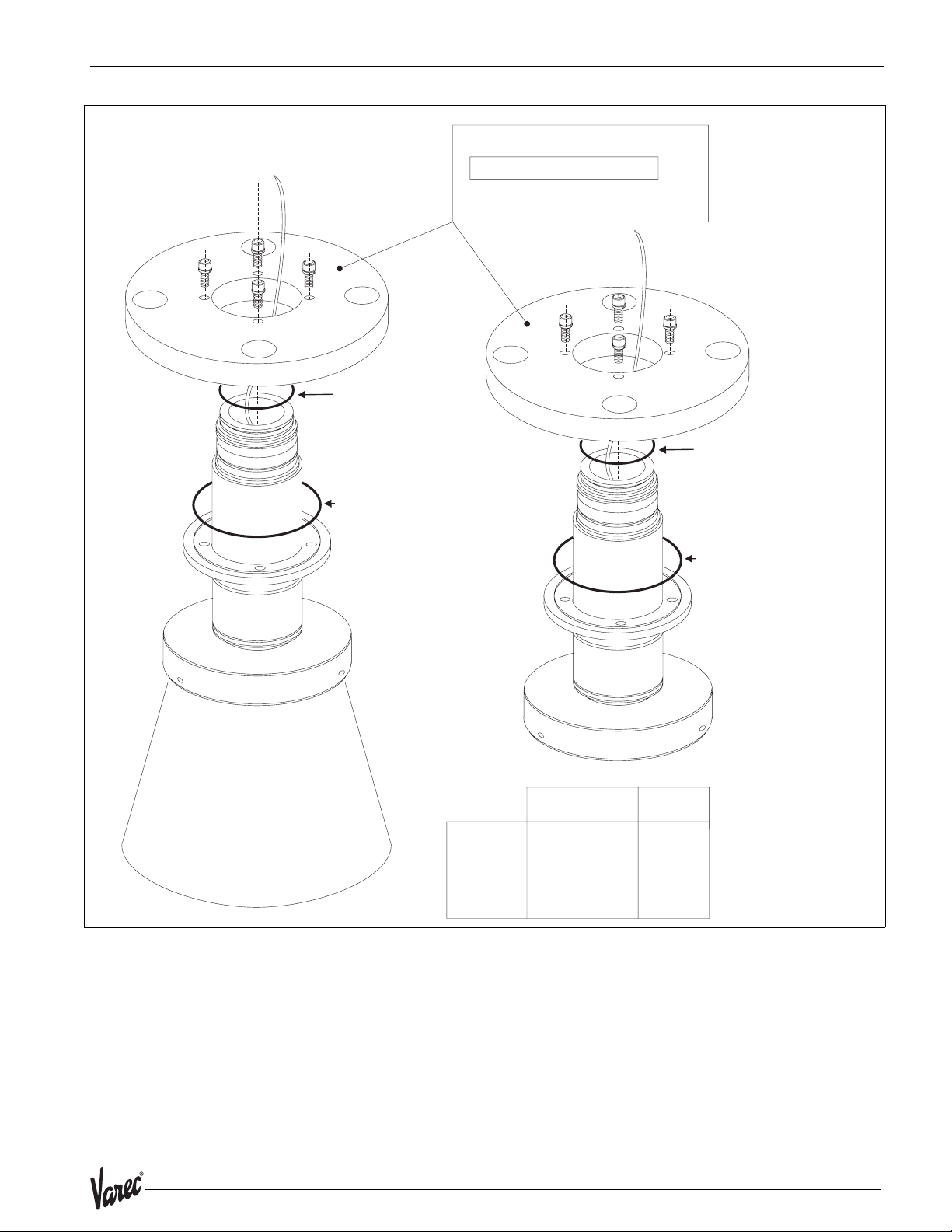
7532 Troubleshooting
Spare parts 7532 RTG
Planar antenna
O-ring 49,21 x 3,53 EPDM
(Seal set 52005628)
O-ring
85,32 x 3,53 FKM (green)
85,32 x 3,53 HNBR12-70
(black)
Process connection without antenna
7532 RTG-
detailed order structure and variants
see spare parts price list
O-ring 49,21 x 3,53 EPDM
(Seal set 52005628)
O-ring
85,32 x 3,53 FKM (green)
85,32 x 3,53 HNBR12-70
(black)
Antenna size Seal
5200 6193 DN 150 ( 6") HNBR
5200 6332 DN 150 ( 6") FKM
5200 6194 DN 200 ( 8") HNBR
5200 6333 DN 200 ( 8") FKM
5200 6195 DN 250 (10") HNBR
5200 6334 DN 250 (10") FKM
Modification nameplate
When ordering parts that are listed in the product structure (see page 8) , a check must
be made as to whether the instrument description on the nameplate is still valid, e.g. for:
• an antenna component,
• an electronics module,
•an RF module,
• a VU 331 operating and display module,
• a housing cover with window.
85
L00-FMR532xx-00-00-06-en-004
Page 86
Troubleshooting Radar Tank Gauge
Housing T12
The complete order code must be specified when ordering the replacement housing so
that the correct nameplate can be delivered, e.g.
• 7532 RTG-AACWJAC1AA
You must label the nameplate yourself.
Caution!
• It is not possible to convert a standard instrument into an Ex instrument by simply
exchanging parts.
• When repairing certified instruments, the relevant regulations must be followed.
• For FM approved instruments, it is forbidden to make any changes to the instrument
that are not expressly authorized in the operating manual. Contravening this
prohibition can invalidate the approval for operation of the instrument.
9.5 Return
If you need to send a 7500 RTG back to Varec for repair, please send a completed copy
of the form printed on the last page.
• An exact description of the application.
• The chemical and physical characteristics of the product.
• A short description of the error that occurred.
• If necessary, give the error code.
Please carry out the measures described in section 1.4, “Return” on page 5 before
sending a 7500 RTG back for repair.
9.6 Disposal
In case of disposal please separate the different components according to their material
consistence.
9.7 Software history
Software version
/ Date
V 1.00.00 /
12.2000
Software changes Documentation changes
Original software.
Operated via:
– ToF Tool
– Commuwin II (from version
2.05.03)
– HART communicator DXR 375
with Rev. 1, DD 1.
V 01.02.00 /
03.2002
simplified commissioning
history reset in basic calibration.
Operated via:
– ToF Tool (V3.0)
– Commuwin II (from version
2.05.03)
– HART communicator DXR 375
with Rev. 1, DD 1.
86 Installation and Operations Manual
Page 87
7532 Technical data
10 Technical data
10.1 Technical data at a glance
Application
Application The 7500 RTG is used for highly accurate level measurement in
storage tanks and can be applied in custody transfer applications. It
meets the relevant requirements according to OIML R85 and API 3.1B.
• The 7532 RTG with planar antenna is specifically and only suited for
stilling well applications with ranges up to 38 m (124 ft).
Function and system design
Measuring principle The 7500 RTG is a "downward-looking" measuring system, operating
based on the time-of-flight method. It measures the distance from
the reference point (process connection) to the product surface. Radar
impulses are emitted by an antenna, reflected off the product surface
and received again by the radar system.
Equipment architecture The 7500 RTG can be used for measurement in a stilling well as well
as in free space. The different instrument versions are applied as
follows:
• The 7532 RTG with planar antenna is the preferred device in stilling
wells
• The instruments are equipped with a passive 4…20 mA output with
≥ 150 mm.
HART protocol.
Input
Measured variable The measured variable is the distance between a reference point
(mounting flange) and a reflective surface (e.g. medium surface). The
measured value and all parameters are displayed using either metrical
SI-units or US/UK-units (inch, ft, …).
The level is calculated based on the tank height entered.
The level can be converted into other units (volume, mass) by means
of a linearization.
In order to compensate for non-linear effects like movement of the
tank roof, an additional correction table (diptable) can be entered.
Measuring range Seepage15
Output
Output signal 4…20 mA with HART protocol:
this version can be operated via the PC operating software ToF Tool
and Commuwin II. The instrument supports both point-to-point and
multidrop operation.
Signal on alarm Error information can be accessed via the following interfaces:
•Local display:
– Error symbol (see page 35)
– Plain text display
– LED’s: red LED continuously on = alarm, red LED flashes = warn-
ing
• Current output
• Digital interface
Galvanic isolation 500 V towards ground.
500 V between power supply and signal
87
Page 88
Technical data Radar Tank Gauge
Auxiliary energy
Electrical connection Housing T 12 with separate terminal compartment.
Load HART Minimum load for HART communication: 250
Cable entry Cable gland: M20x1.5 or Pg13.5
Cable entry: G ½ or ½ NPT
Supply voltage Seepage28
Power consumption Max. 330 mW at 16 V, max. 500 mW at 24 V, max. 600 mW at 30 V.
Current consumption Max. 21 mA (50 mA inrush current).
Power supply For stand alone operation recommended via e.g. Varec RN 221N/Z.
Ω
Performance characteristics
Reference operating
conditions
Maximum measured
error
Proof of accuracy for
custody transfer versions
According to OIML R85:
• Temperature = –25…+55 °C (-13…+131 °F)
• Atmospheric pressure
• Relative humidity (air) = 65 % ±15%
• Medium properties: e.g. medium with good reflectivity and calm
surface.
• Tank diameter: signal beam hits the tank wall only at one side.
Note!
No major interference reflections inside the signal beam.
Absolute accuracy: 0.5 mm (2σ value)
Inventory Control Versios: ±3 mm
The accuracy of each 7500 RTG is established through a calibration
certificate that records the absolute and relative error at 10
equidistant points during the final test. For stilling well measurements
with 7532 RTG, a NMI / PTB calibrated tape with an absolute accuracy
of 0.25 mm is used.
Each 7500 RTG is delivered with the PTB and NMi type approval.
Additional initial factory verifications for custody applications are
available on demand for all 7500 RTG.
Maximum fill speed By the first pass trough of measuring range: 100 mm/min., after it
Non-repeatability 0,3 mm (1/64")
Hysteresis 0.3 mm
Resolution digital: 0.1 mm
Settling time Typical 15 sec
Long-term drift The long-term drift is within the specified accuracy.
Influence of ambient
temperature
Software reliability The software used in the 7500 RTG fulfills the requirements of OIML
unlimited.
analogue: 0.03 % of measuring range
Within the specified accuracy according to OIML R85.
R85. This particularly includes:
• cyclical test of data consistency
• non-volatile memory
•segmented data storage
The 7500 RTG continuously monitor the compliance with accuracy
requirements for custody transfer measurements according to OIML
R85. If the accuracy cannot be maintained, a specific alarm is
generated on the local display and via the digital communication.
88 Installation and Operations Manual
Page 89
7532 Technical data
Inventory Control Versions
All device types can be delivered as "Inventory Control Versions" with a
reduced accuracy of ± 3mm (under reference conditions).
To these versions, the calibration certificate or custody transfer type
approval is NOT attached.
The "Inventory Control Versions" can be selected by choosing the
option »R« in feature »70« in the order code section »Custody transfer
approvals« on page 8.
Operating conditions
Operating conditions
Engineering tips Seepage14
Environment
Ambient temperature
range
Storage temperature -40 °C ... +80 °C (-40 °F … +176°F)
Climate class DIN EN 60068-2-38 (test Z/AD)
Ambient temperature for the transmitter:
• Standard: -40 °C … +80 °C (-40 °F … +176 °F)
• For calibration to regulatory standards: -25 °C ... +60 °C (-30
°F…+140 °F)
With T
<-20 °C and Tu>+60 °C the operability of the LC-display is
u
reduced.
A weather protection cover should be used for outdoor operation if
the instrument is exposed to direct sunlight.
Degree of protection • housing: IP 65, NEMA 4X (open housing: IP20, NEMA 1)
• antenna: IP 68 (NEMA 6P)
Vibration resistance DIN EN 60068-2-64 / IEC 68-2-64: 20…2000 Hz, 5 (m/s²)²/Hz
Cleaning of the antenna See
Electromagnetic compatibility
»Technical Information« TEC028
• emissions according to EN 61326; equipment class B
• compatibility according to EN 61326; appendix A (industrial area,
10 V/m) and Namur recommendation EMC (NE 21).
Process conditions
Process temperature
range
Process temperature
limits
Process pressure limits See
Dielectric constant • in a stilling well:
Wetted parts • Planar, gas-tight
See »Technical Information« TEC028
»Technical Information« TEC028
See
»Technical Information« TEC028
εr ≥ 1.4
• in free space:
Wetted parts: 1.4435 / HNBR (Hydrated Nitrit Butadien Rubber,
resistent to NH
Note!
The planar antenna is not resistant to hot vapor!
• Horn adapter for increase of diameter
Wetted parts: 1.4435
εr ≥ 1.9
) or FKM / PTFE glas fiber laminat
3
89
Page 90
Technical data Radar Tank Gauge
Mechanical construction
Design, dimensions Seepage13
Weight Approx 6 kg + weight of flange
Material Seepage8
Process connection see page 8
All process connections dispose of a gas-tight glass feed-through to
prevent any gas leakage to the inside of the housing.
Human interface
Operation concept Seepage31
Display Seepage31
Certificates and approvals
CE approval The measuring system meets the legal requirements of the EC-
RF approvals R&TTE 1999/5/EG, FCC CRF 47, part 15
Overspill protection PTB , NMi and many other national approvals
External standards and
guidelines
guidelines. Varec confirms the instrument passing the required tests
by attaching the CE-mark.
EN 60529
Protection c3lass of housing (IP-code)
EN 61010
Safety regulations for electrical devices for measurement, control,
regulation and laboratory use.
EN 61326
Emissions (equipment class B), compatibility (appendix A – industrial
area)
NAMUR
Standards committee for measurement and control in the chemical
industry
API (American Petroleum Institute)
Particularly "Manual of Petroleum Measurement Standards".
OIML R85 (Organisation Internationale de Metrologie Legale)
Ex approval
XA 081F-A
Installation 7500 RTG (T12 / EEx ia IIC T6…T1)
PTB 00 ATEX 2067 X, Equipment marking: (II 1/2 G)
Ordering Information
The Varec service organisation can provide detailed ordering
information an information on the order codes on request.
Accessories
see page 75
Supplementary Documentation
Supplementary
Documentation
90 Installation and Operations Manual
•System Information
• Technical Information
• Operating Instructions
Page 91

7532 Appendix
11 Appendix
11.1 Operating menu HART (Display modul), ToF Tool
91
Page 92
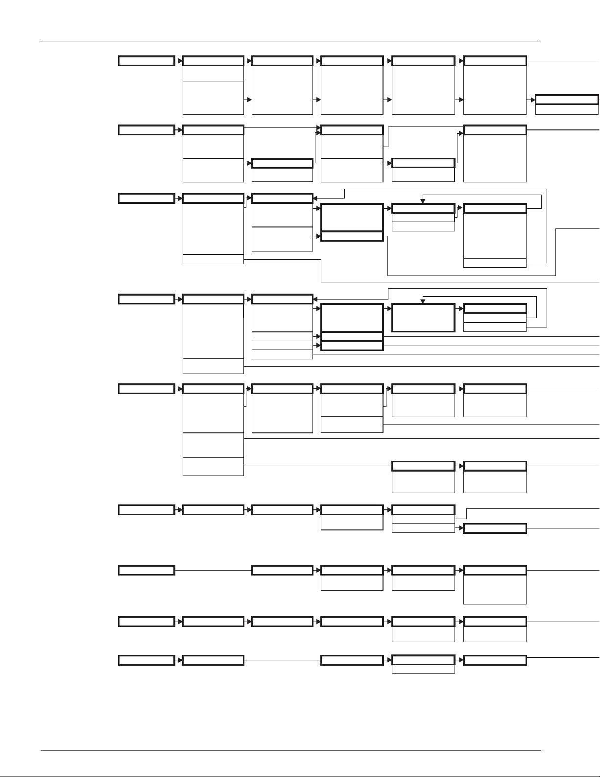
Appendix Radar Tank Gauge
basic setup
safety settings
mounting calibr.
linearisation
00
01
03
04
tank shape
dome ceiling
horizontal cyl.
bypass
stilling well
flat ceiling
sphere
output on alarm
MIN -10% 3.6mA
MAX 110% 22mA
hold
user specific
tank gauging
dip table
auto correct.
level/ullage
level CU
ullage CU
level DU
ullage DU
medium property
002
unknown
DK: < 1.9
DK: 1.9 … 4
DK: 4 … 10
DK: > 10
010
output on alarm
enter value enter value
dip table mode
030
view
manual
semi-automatic
table on
table off
clear table
linearisation
040
manual
040
semi-automatic
table on
horizontal cyl
linear
reset table
040
003
011
033
041
041
process cond.
standard
calm surface
turb. surface
add. agitator
fast change
test: no filter
outp. echo loss
alarm
hold
ramp %MB/min
dip table state
dip table state
customer unit
customer unit
customer unit
empty calibr.
004
enter value
012
ramp %/min
dip table
037 034
meas.v.
dip value
037
linearisation
042
table no.
input level
input volume
042
042
005
013
034
035
043
044
045
full calibr.
enter value
delay time
in case of echo loss
max. 4000 sec.
default: 30 s
dip table handl.
next point
previous point
new point
edit point
store point
delete point
return
next point
yes
no
006
014
036
045
pipe diameter
enter value
007
extended calibr.
output
display
diagnostics
system parameter
05
06
09
0A
0C
selection
mapping
common
extended map..
commun. address
present error
tag no.
050
060
0A0
0C0
dist./meas value
D and L
are displayed
no. of preambels
language
previous error
008
061
092
0A1
check distance
distance = ok
dist. too small
manual
dist. unknown
dist. too big
low output limit
off
on
back to home
enter time
default: 100 s
clear last error
protocol+sw-no.
051
062
093
0A2
0C2
range of mapping
input of
mapping range
pres. Map dist
is displayed
fixed current
off
on
format display
decimal
1/16”
reset
for reset code
see manual
software no.
custody transfer
Note! The default values of the parameters are typed in boldface.
052
054
063
094
0A3
0C3
start mapping
off
on
cust. Tank map
inactive
active
reset
fixed cur. value
no. of decimals
x
x.x
x.xx
x.xxx
unlock parameter
for reset code
see manual
serial no.
053
055
064
095
0A4
0C4
92 Installation and Operations Manual
Page 93
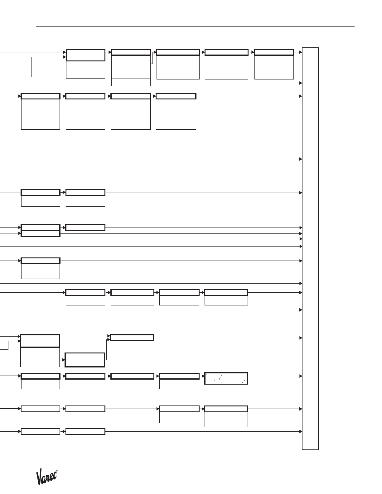
7532 Appendix
safety distance
from blocking
distance
default: 0.1m
auto correction
off
on
max. scale
max. scale
015
031
046
046
dist./meas.value
D and L
are displayed
in safety dist.
alarm
warning
self holding
pipe diam. corr.
off
on
diameter vessel
008
check distance
distance = ok
dist. too small
dist. too big
manual
dist. unknown
ackn. alarm overspill protection
016
no
yes
032
047
051
017 018
range of mapping
input of
mapping range
standard
german WHG
052
start mapping
off
on
053
history reset
no
yes
009
dist./meas.value
D and L
are displayed
simulation
sim. off
sim. level
sim. volume
sim. current
sep. character
. point
, comma
measured dist.
distance unit
008
065
096
0A5
0C5
echo quality
is displayed
simulation value
display test
off
on
measured level
download mode
056
066
097
0A6
0C8
offset
will be added to the
measured level
output current
plot settings
envelope curve
env.curve+FAC
env.curve+cust.map
057
067
09A
output damping
enter value
default: 5 s
recording curve
single curve
cyclic
application par.
not modified
modified
058
09B
0A8
blocking dist.
is displayed
custody mode
inaktiv
aktiv positiv
aktiv negativ
Return to Group Selection
059
0A9
93
Page 94

Appendix Radar Tank Gauge
11.2 Operating matrix HART / Commuwin II
94 Installation and Operations Manual
Page 95
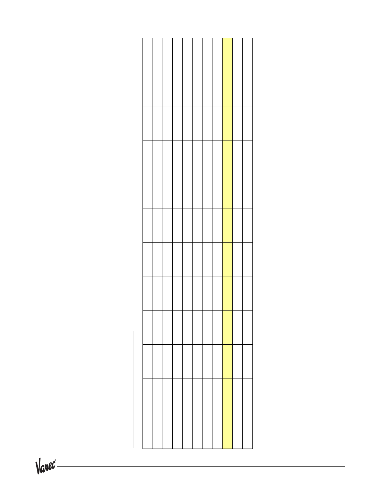
7532 Appendix
Operating Matrix HART / COMMUWIN II
Function group V-CWII H0 H1 H2 H3 H4 H5 H6 H7 H8 H9
00 basic setup V0 measured value tank shape medium property process cond. empty calibr. full calibr. pipe diameter
01 safety settings V1 output on alarm output on alarm outp. echo loss ramp %span/min delay time safety distance in safety dist. ackn. alarm overspill protection
03 mounting calibr. V2 tank gauging auto correction pipe diam. corr. dip table mode dip table dip table dip table handl. dip table state
04 linearisation V3 level/ullage linearisation customer unit table no. input level input volume max. scale diameter vessel
05 extended calibr. V4 check distance range of mapping start mapping pres. Map dist cust. Tank map echo quality offset output damping blocking dist.
06 output V5 commun. Address no. Of preambels low output limit fixed current fixed current simulation simulation value output current
09 display V6 language back to home format display no. of decimals sep. character
0D service V7
0A diagnostics V9 present error previous error clear last error reset unlock parameter measured dist. measured level application par. custody mode
0C system parameter VA tag no. protocol+sw-no. software no. serial no. distance unit download mode
95
Page 96

Appendix Radar Tank Gauge
11.3 Description of functions
Note!
A detailed description of the function groups, functions and parameters is given in the
the 7500 RTG "Service manual and description of instrument functions".
96 Installation and Operations Manual
Page 97
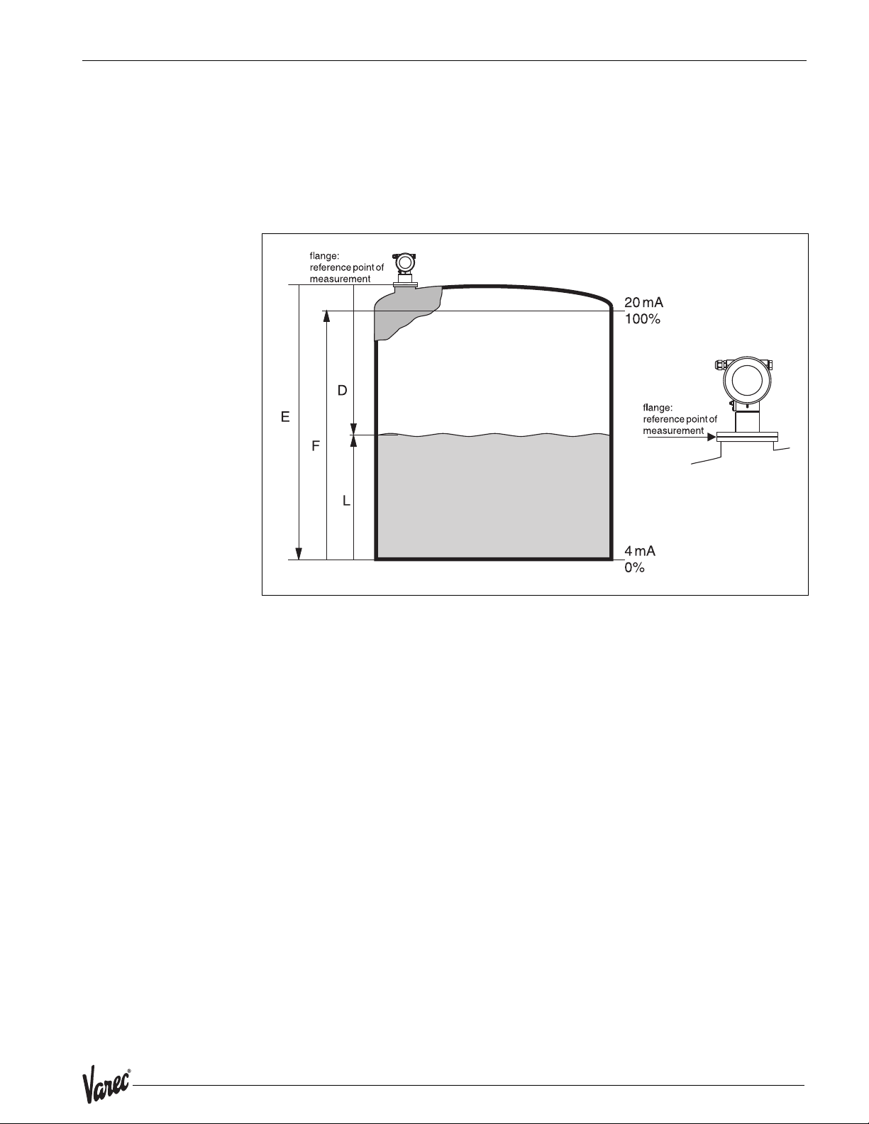
7532 Appendix
11.4 Function and system design
11.4.1 Measuring principle
The 7500 RTG is a "downward-looking" measuring system, operating based on the
time-of-flight method. It measures the distance from the reference point (process
connection) to the product surface. Radar impulses are emitted by an antenna, reflected
off the product surface and received again by the radar system.
Input
The reflected radar impulses are received by the antenna and transmitted into the
electronics. A microprocessor evaluates the signal and identifies the level echo caused
by the reflection of the radar impulse at the product surface. The unambiguous signal
identification is accomplished by the PulseMaster® software based on many years of
experience with time-of-flight technology. The mm-accuracy of the 7500 RTG is
achieved with the patented algorithms of the PhaseMaster® software.
The distance D to the product surface is proportional to the travel time t of the impulse:
D = c · t/2,
with c being the speed of light.
Based on the known empty distance E, the level L is calculated:
L = E – D
Reference point for "E" is the lower surface of the process connection.
The 7500 RTG is equipped with functions to suppress interference echoes. The user can
activate these functions. They ensure that interference echoes (e.g. from edges and weld
seams) are not interpreted as level echo.
L00-FMR53xxx-15-00-00-en-001
97
Page 98
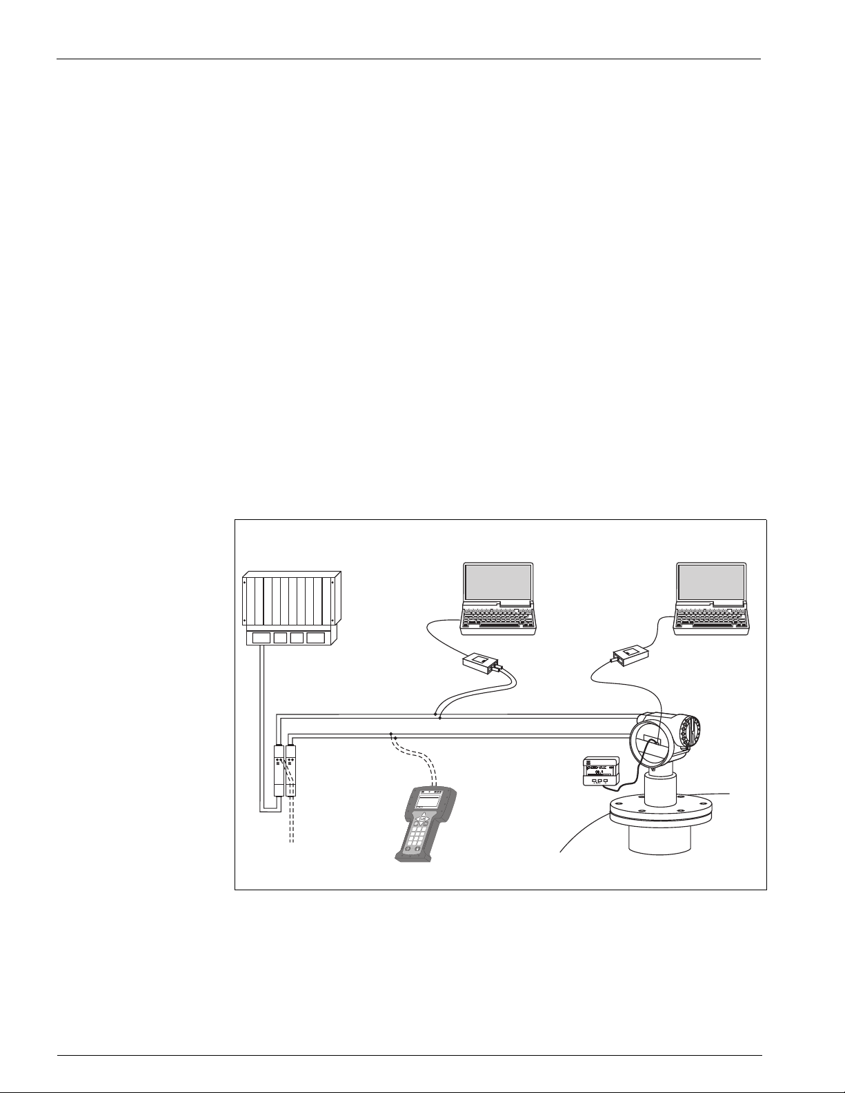
Appendix Radar Tank Gauge
Output
The 7500 RTG is commissioned by entering an empty distance E (=zero), a full distance
F (=span), and an application parameter. The application parameter automatically
adapts the instrument to the measuring conditions. The data points “E” and “F”
correspond with 4mA and 20mA for instruments with current output. They correspond
with 0 % and 100% for digital outputs and the display module.
A linearization with max. 32 points, based on a table entered either manually or semiautomatically, can be activated locally or remotely. This function provides a
measurement in engineering units and a linear output signal for spheres, horizontal
cylindrical tanks, and vessels with conical outlet.
11.4.2 Equipment architecture
Stand-alone
The 7500 RTG can be used for measurement in a stilling well as well as in free space.
The different instrument versions are applied as follows:
• The 7532 RTG with planar antenna is the preferred device in stilling wells ≥ 150 mm.
• The 7530 RTG with horn antenna can be used in stilling wells with a diameter
<150 mm. However, for these diameters no custody transfer approval is available.
• The 7533 RTG with parabolic antenna is preferred for free-space measurements. The
7530 RTG with horn antenna can be used as an alternative for small nozzle diameters.
• The 7531 RTG with rod antenna (PTFE) should be used for measurements of highly
aggressive media (e.g. sulphur).
• The instruments are equipped with a passive 4…20 mA output with HART protocol.
The complete measuring system consists of:
SPS
- COMMUWIN II
- ToF Tool
Commubox
FXA 191
HART
2x Messumformer-
speisegerät
RN 221 N
FXA 191
oder
DXR 375
dsdmdm
dsdmdm
df das.
df das.
asdas fa
asdas fa
asas la.
asas la.
DELTABAR:* * * * * * * *
DELTABAR:* * * * * * * *
ONLINE
ONLINE
1 QUICK SETUP
1 QUICK SETUP
2 OPERATING MENU
2 OPERATING MENU
3 PV 352 mbar
3 PV 352 mbar
4 SV 0 °C
4 SV 0 °C
HELP SAVE
HELP SAVE
6
6
Page
Page
Up
Up
9
9
DeleteBksp
DeleteBksp
Page
Page
On
On
# % &
A B C
# % &
A B C
D E F
D E F
1
3
1
3
2
2
Copy
Paste
Copy
Paste
Hot Key
Hot Key
G H I
G H I
J K L
M N O
J K L
M N O
6
6
5
5
4
4
Insert
+ Hot Key
Insert
+ Hot Key
P Q R S
P Q R S
T UV
W XY Z
T UV
W XY Z
8
8
9
9
7
7
, ( )‘
, ( )‘
_ < >
+ * /
_ < >
+ * /
-
-
.
0
.
0
HART-Handbediengerät
375
375
FIELD COMMUNICATOR
FIELD COMMUNICATOR
DXR 375
HART
Anzeige- und
Bedienmodul
VU 331
ENDRESS + HAUSER
- ToF Tool
Service-Adapter
FXA 193
%
+–
E
L00-FMR53xxx-14-00-06-en-002
98 Installation and Operations Manual
Page 99
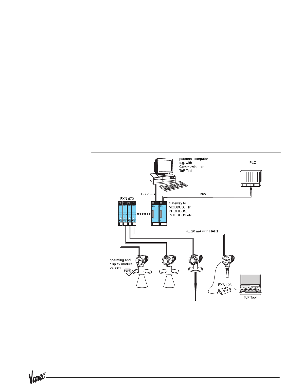
7532 Appendix
On-site operation:
• with display and operating module VU 331,
• with a Personal Computer, FXA 193 and the operating software ToF Tool.
The ToF Tool is a graphical operating software for instruments from Varec that operate
based on the time-of-flight principle (radar, ultrasonic, guided micro-impulse). It
assists with commissioning, securing data, troubleshooting, and documentation of the
measuring point.
Remote operation:
• with HART handheld DXR 35,
• with a Personal Computer, Commubox FXA 191 and the operating software
COMMUWIN II respectively ToF Tool.
• With a Personal Computer, TSM (Tank Side Monitor) and the operating software
FuelsManager.
System integration via Rackbus
Multiple 7500 RTG (or other instruments) can be connected to a higher-level bus system
via a Gateway ZA:
• Every HART transmitter via one interface module FXN 672 each.
• Gateways are available for MODBUS, FIP, PROFIBUS, INTERBUS etc.
• Both on-site as well as remote operation are possible.
Integration into the Asset Management System
The HART interface allows the integration into the AMS® (Asset Management System)
from Fisher-Rosemount.
L00-FMR53xxx-14-00-06-en-003
99
Page 100

Appendix Radar Tank Gauge
11.4.3 Custody transfer mode
7500 RTG is a weight and measure approved level transmitter. Either the innage or the
ullage can be selected as the custody transfer variable.
The selected variable is the basis for the subsequent calculation of the current amount
of product in a tank, along with other measured variables such as (average) temperature
and pressure.
This opens up numerous application options in custody transfer:
• Quantity calculation of mineral oils
• Quantity calculation of alcohols
11.4.4 Weight and measure approval, Standards Authorities approval, Compulsory reapproval
The
type approvals for custody transfer
enclosed with every device, prove the fundamental suitability of the various types for
custody transfer.
issued by the PTB and NMi, a copy of which is
In addition to this, the
certificate, which is issued in the factory after the device has been tested on a reference
test rig.
On request, a separate
National Standards Authorities inspector present, who issues a
for every device. In the initial verification, the device is tested to ensure that it com-
cate
plies with the
devices in Germany.
Essentially, this proves that the devices are
must not, however, be used in custody transfer mode straight away.
The measuring device is not approved until after the
Standards Authorities. For this, the device's level measurement is compared with the
tank gauging by a National Standards Authorities inspector using manual dips (also "Initial verification"). As a rule, a quiescent tank gauging is dipped by hand three times in a
row and then compared with the value displayed by the level radar. Depending on
national regulations, the transfer error limit, calculated as the arithmetic mean of the
absolute deviations of all three measurements, must not exceed double the limit of error
in legal metrology (compare, for example, the German "Eichordnung" or the American
"API 3.1B", in which the necessary procedures are also defined).
Depending on national regulations, this test is repeated with various tank gaugings.
Using linearization tables to compensate any non-linearities that occur in measurement
is permitted. For this, the 7500 RTG level radar offers a special dip table, compare
“Mounting calibration with VU 331” on page 57.
limit of error in legal metrology
accuracy
initial verification
of every single device is documented using a calibration
of the devices can be carried out with a
preliminary test certifi-
, which lies at +-2mm for radar measuring
weight and measure approved
approval after installation
. The devices
by the
After the measurement has been approved by an inspector, he seals the level radar at
the stamp position and thereby also secures the programming status of the device.
Those operating an approved level transmitter are obligated to obtain
accordance with the applicable national regulations from the Standards Authorities.
100 Installation and Operations Manual
reapproval
in
 Loading...