

Page 1
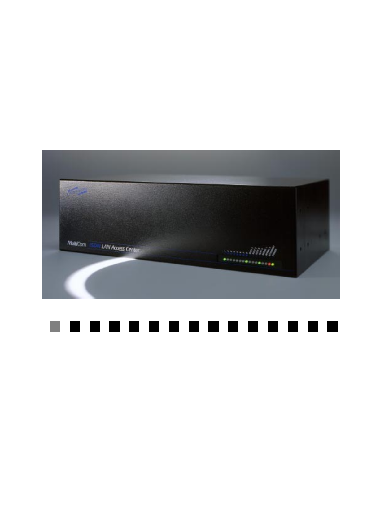
Multi Com LAN
Access Center
User’s Manual
Version 1.5 - 99/2/25
Page 2

❏
❏
❏
❏
❏
❏
❏
❏
❏
❏
❏
❏
P
ACKING
✔
1
Multi Com LAN Access Center
… LACxPRI with one shielded ISDN cable (option)
… LACx4BRI with four ISDN cables (option)
✔
1 Power cable
✔
1 Straight Ethernet cable
✔
1 DB9 console cable
✔
2 Rack mount metal pieces with 8 screws
✔
4 Plastic legs
L
IST
✔
1 User’s Manual with Warranty Registration Card for one free update
✔
1 CD-ROM including the Reference Manual and configuration software
… CBL-530F-V35M (option)
… CBL-530F-X21M (option)
Page 3

Warranty
1
Warranty
Multi Com LAN Access Center — User’s Manual
I
Page 4

W
ARRANTY
C
OPYRIGHT
NO WARRANTIES ARE EXTENDED BY THIS DOCUMENT. The technical
information in this document is proprietary to LIGHTNING Instrumentation S.A.
and the recipient has a personal, non–exclusiv e and non transferable license to use
this information solely with the use of LIGHTNING Instrumentation products.
The only product warranties made by LIGHTNING Instrumentation, if any, are
set forth in the agreed terms and conditions for the purchase of LIGHTNING
Instrumentation products. LIGHTNING Instrumentation declaims liability for
any and all direct and indirect damages that may result from publication or use of
this document and/or its contents.
The information in this document is subject to change without notice. Revisions
may be issued at any time.
Copyright © 1997-1999 LIGHTNING Instrumentation SA. No part of this document may be reproduced in any manner without the prior written consent of
LIGHTNING Instrumentation SA
W
ARRANTY
LIGHTNING Instrumentation SA warrants all hardware products of its manufacture to be free from defects in material and workmanship for 12 months from date
of delivery. Opening the cover voids the warranty.
Upon prompt notification by the purchaser, Lightning will correct, within the w ar ranty period, any defects in equipment of its manufacture, either by repair at its
factory or by supply of replacement parts to the purchaser.
ON
H
ARDWARE
Lightning must decide to its own satisfaction that the equipment is defective and
has not developed malfunctions as a result of misuse, modification, or abnormal
conditions of operation. Opening the products also voids the warranty. Lightning
assumes no liability for consequential damages, and its liability shall in no case
exceed the original purchase price of the equipment.
II
Multi Com LAN Access Center — User’s Manual
Page 5

W
ARRANTY
LIGHTNING Instrumentation SA provides no warranty on software and
firmware. Software and firmware are provided “as is” and no w arranty is made for
perfect function or fitting to particular applications.
Lightning provides its best effort in issuing high quality software and firmware,
and will devote its best effort in finding and correcting potential problems occurring with other equipment following international standards, but does not make
any express warranty to correct such problems, if they arise. Lightning assumes
no liability for consequential damages, and its liability shall in no case exceed the
original purchase price of the equipment.
The warranties set forth above for hardware, software and firmware are the sole
warranties applicable to Lightning products. THE IMPLIED WARRANTY OF
MERCHANTABILITY AND ALL OTHER WARRANTIES, EXPRESS OR
IMPLIED, ARE EXCLUDED.
ON
S
OFTWARE
AND
F
IRMWARE
IMITATION
L
UNDER NO CIRCUMSTANCES, INCLUDING NEGLIGENCE, SHALL
LIGHTNING INSTRUMENTATION SA BE LIABLE FOR LOSS OF USE,
INTERRUPTION OF BUSINESS, OR ANY INDIRECT, SPECIAL, INCIDENTAL, OR CONSEQUENTIAL DAMAGES OF ANY KIND (INCLUDING
LOST PROFITS) REGARDLESS OF THE FORM OF ACTION WHETHER IN
CONTRACT, TORT (INCLUDING NEGLIGENCE), STRICT PRODUCT LIABILITY OR OTHERWISE, EVEN IF LIGHTNING HAS BEEN ADVISED OF
THE POSSIBILITY OF SUCH DAMAGES.
In no event shall Lightning be liable for costs of procurement of substitute goods.
The potential liability of Lightning arising out of this product is in any case limited to the purchase price paid to Lightning for its products.
OF
IABILITY
L
Multi Com LAN Access Center — User’s Manual
III
Page 6

W
ARRANTY
ISDN C
In no event shall Lightning be liable for costs incurred by a user on its ISDN line.
The
Multi Com LAN Access Center
matically, depending on traffic on the Ethernet and ISDN line and on parameters
set in the configuration. Front-panel signals and specific commands may indicate
the current state and activity of the ISDN line, and the user should keep an eye on
those status indications to avoid excessive bills, due to misconfiguration, protocol
errors, polling applications, potential software or firmware errors and so forth.
THE USER AND THE USER ONLY IS SOLELY RESPONSIBLE
FOR ALL INCURRED ISDN COSTS.
RADEMARKS
T
OSTS
is designed to open and close ISDN lines auto-
Multi Com
tion SA. All other trademarks are property of their respective owners.
R
EVISIONS
The information in this document is subject to change without notice. Revisions
may be issued at any time. Watch http://www
the latest revision of our manuals.
LIGHTNING Instrumentation SA
Avenue des Boveresses 50
1010 Lausanne
SWITZERLAND
Phone: +41 21 654-2000
Fax: +41 21 654-2001
E-mail: [email protected]
Web: www.lightning.ch
and Lightning are registered trademarks of LIGHTNING Instrumenta-
.lightning.ch/products/manual for
IV
Multi Com LAN Access Center — User’s Manual
Page 7

Contents 2
INSTALLATION ...................................... 7 C HAPTER 1
HECKING YOUR PACKAGE CONTENTS ..................8 § 1.1
C
Contents
TO RETURN THE PRODUCT......................................8 § 1.2
CONNECTING THE CONSOLE....................................9 § 1.3
CONNECTING THE ETHERNET NETWORK ..............11 § 1.4
E
THERNET PORTS ..............................................................11 § 1.4.1
THERNET LEDS...............................................................12 § 1.4.2
E
INSTALLATION FOR THIN ETHERNET ................................13 § 1.4.3
INSTALLATION FOR TWISTED-PAIR ETHERNET..................14 § 1.4.4
CONNECTING SERIAL DEVICES..............................15 § 1.5
CONNECTING PRI CARDS ......................................16 § 1.6
CONNECTING 4BRI CARDS....................................18 § 1.7
CONNECTING THE POWER CABLE .........................20 § 1.8
STARTING UP YOUR MultiCom...........................21 § 1.9
GETTING S TARTED ...............................23 C HAPTER 2
O NOT CONNECT TO A NETWORK BEFORE….......24 § 2.1
D
EASYCONFIG .........................................................24 § 2.2
NSTALLING EASYCONFIG ON WINDOWS 95/98/NT.........24 § 2.2.1
I
MultiCom LAN Access Center — User’s Manual V
Page 8

CONTENTS
USING EASYCONFIG..........................................................25 § 2.2.2
USING EASYCONFIG TO SET STATIC IP ADDRESSING .......26 § 2.2.3
USING EASYCONFIG WITH EXAMPLE CONFIGURATIONS ..26 § 2.2.4
REFERENCE MANUAL, WEB, AND FAQ................27 § 2.3
FINE-TUNING THE CONFIGURATION.......................27 § 2.4
CONNECTING TO THE COMMAND INTERFACE .......27 § 2.5
SING TELNET TO ACCESS THE COMMAND INTERFACE...27 § 2.5.1
U
USING THE CONSOLE.........................................................28 § 2.5.2
TESTING ............................................. 29 C HAPTER 3
REQUENTLY ASKED QUESTIONS (FAQ)..............30 § 3.1
F
GENERAL TROUBLE-SHOOTING SCHEME ..............32 § 3.2
CONNECTING TO A DISTANT SITE .........................33 § 3.3
CHECKING THE ETHERNET CONNECTION..............33 § 3.4
CHECKING THE ISDN CONNECTION......................33 § 3.5
FURTHER TROUBLE-SHOOTING .............................34 § 3.6
CONFIGURATION ..................................35 C HAPTER 4
NSTALLING FOR CONFIGURATION ........................36 § 4.1
I
DEFAULT CONFIGURATION ...................................36 § 4.2
RESETTING THE DEFAULT CONFIGURATION .........37 § 4.3
APPENDIX ........................................... 39 C HAPTER 5
PECIFICATIONS.....................................................40 § 5.1
S
ULTICOM LAN ACCESS CENTER HARDWARE...............40 § 5.1.1
M
CONSOLE PORT..................................................................40 § 5.1.2
ETHERNET PORTS ..............................................................41 § 5.1.3
SERIAL PORTS....................................................................41 § 5.1.4
ISDN (BRI).......................................................................41 § 5.1.5
ISDN (PRI) .......................................................................41 § 5.1.6
DECLARATION OF CONFORMITY ...........................42 § 5.2
WARRANTY REGISTRATION CARD........................43 § 5.3
VI MultiCom LAN Access Center — User’s Manual
Page 9

Installation
The MultiCom LAN Access Center is a device
designed to connect remote Ethernet networks
through Basic-Rate ISDN, Primary-Rate ISDN or synchronous serial leased lines. It is easy to install and
works with standard T CP/IP and IPX/SPX software. To
set up your MultiCom LAN Access Center, simply follow the steps described in the following chapter.
1
Chapter 1
MultiCom LAN Access Center — User’s Manual 7
Page 10

CHAPTER 1INSTALLATION CHECKING YOUR PACKAGE CONTENTS
CHECKING YOUR PACKAGE CONTENTS
Firstly, please check the packing list on the reverse side of the cover.
If something is missing or if the product is received damaged, forward an immediate request to the delivering carrier to perform an inspection and prepare a
report. Save the container and packing material until contents are verified.
Report the nature and extent of the damage to Customer Support so that action
can be initiated to repair or replace damaged or missing items, or instructions
issued for returning items.
The responsibility of the manufacturer ends at the deliv ery to the first carrier. ALL
CLAIMS for loss, damage, or nondelivery must be made against the delivering
carrier WITHIN 8 DAYS OF RECEIPT of shipment.
1.1
TO RETURN THE PRODUCT
Please obtain instructions from Customer Support before
returning any item(s). Report the fault or deficiency along with the model,
type, and serial number of the item(s) to Customer Support. Upon receipt of this
information, Customer Support will provide service instructions or shipping
information.
1.2
8 MultiCom LAN Access Center — User’s Manual
Page 11
CONNECTING THE CONSOLE
CONNECTING THE CONSOLE
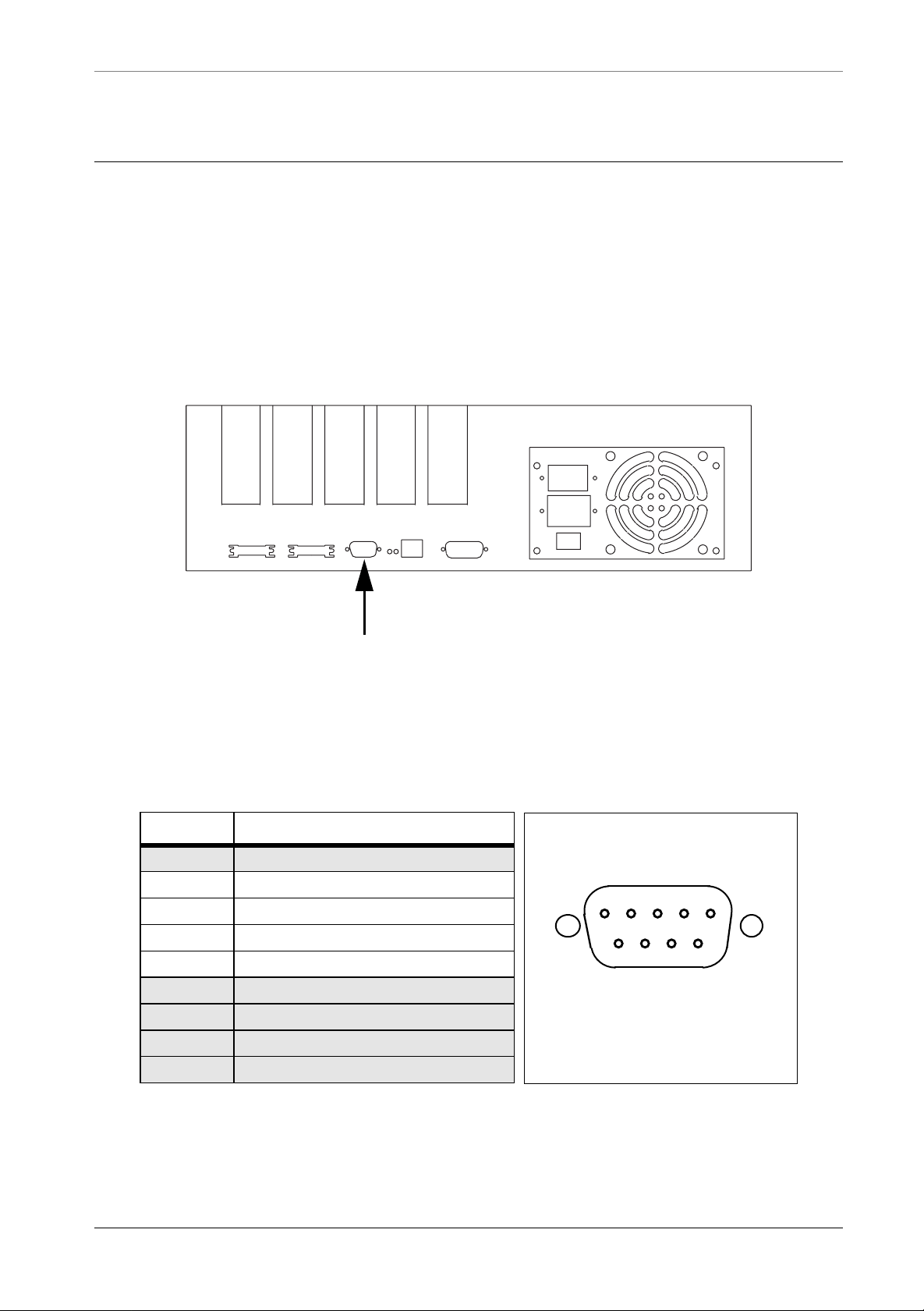
The console port is used to connect a terminal to your MultiCom. The standard
DB-9 connector for this port is located on the rear panel, as shown in Figure 1.
The pin-out for the console connector is shown in Figure 2. The fifth slot is
reserved for future use and cannot accept standard expansion modules.
Slot 1
Slot 2
Slot 3
Console EthernetSerial2Serial1
Slot 4
Slot 5
1.3
Console port
Figure 1 Location of the console connector
Pin # Description
1 (not connected)
2 Receive Data
3 Transmit Data
4 Data Terminal Ready
5 Ground
6 (not connected)
7 (reserved)
8 (reserved)
9 (not connected)
12345
6789
DB-9 male
Figure 2 Pin-out of the console connector.
MultiCom LAN Access Center — User’s Manual 9
Page 12
CHAPTER 1INSTALLATION CONNECTING THE CONSOLE
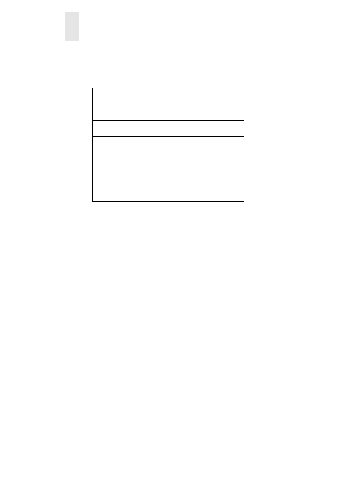
The protocol used by this port is a standard asynchronous serial protocol with the
following parameters :
Protocol Asynchronous
Baud rate 9600 bps
Number of data bits 8
Parity No parity
Number of stop bits 1
Handshake None
Line drivers RS-232, V.28
Figure 3 Serial configuration
10 MultiCom LAN Access Center — User’s Manual
Page 13
CONNECTING THE ETHERNET NETWORK ETHERNET PORTS
CONNECTING THE ETHERNET NETWORK
ETHERNET PORTS
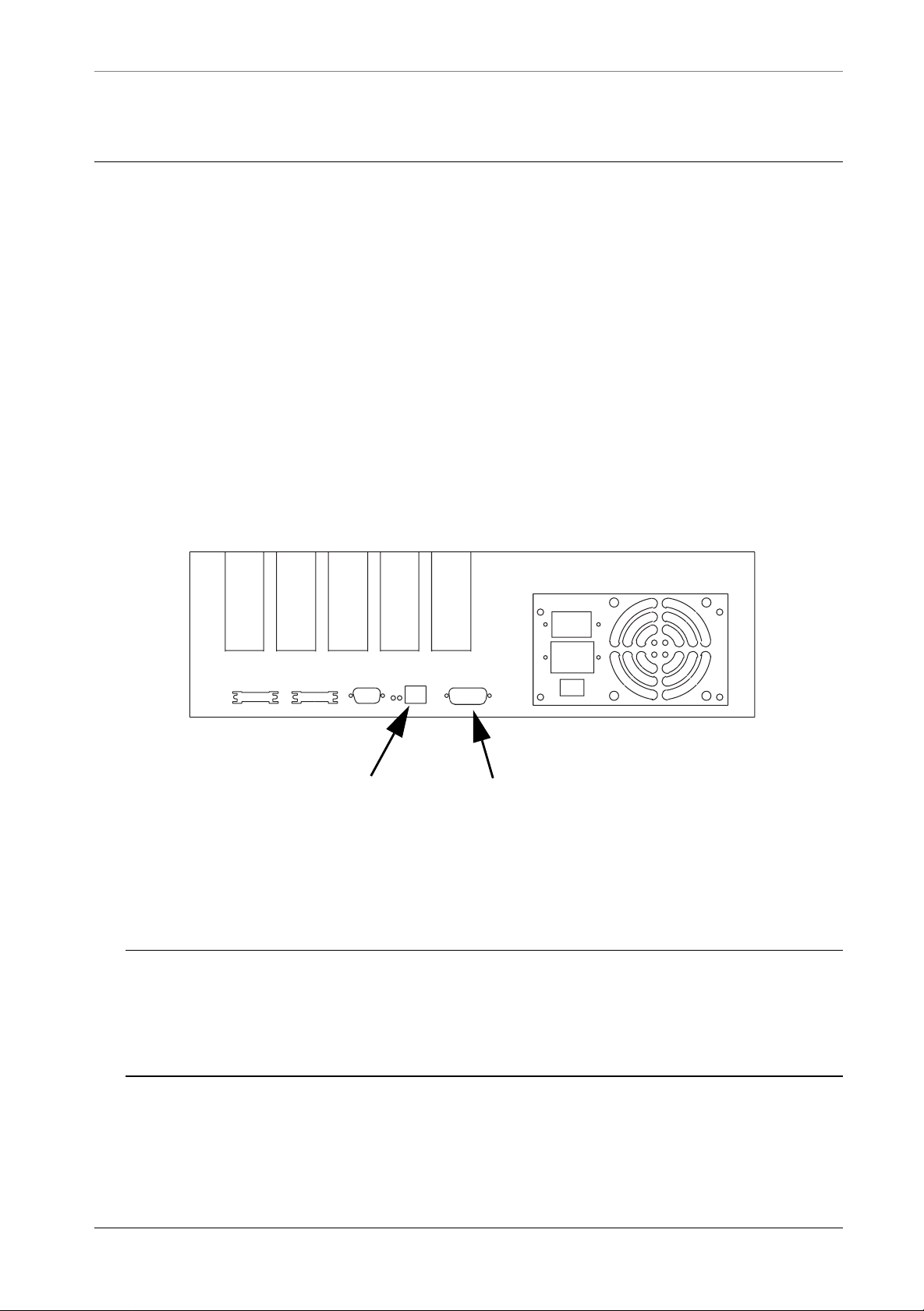
The connection to an Ethernet network may be done in two ways:
1. With the RJ-45 connector, to connect directly a Twisted-Pair (10-Base-T) Ethernet link.
2. With the Adapter Unit Interface (AUI) connector, to connect an adapter to a
Thick (10-Base-5), a Thin (10-Base-2) or an Optical Fiber (10-Base-FL)
Ethernet link.
Slot 1
Slot 2
Slot 3
Slot 4
Slot 5
1.4
1.4.1
Console EthernetSerial2Serial1
RJ-45 AUI
Figure 4 Ethernet connectors
NOTE - The MultiCom LAN Access Center automatically detects the type of Ether-
net connection used. When both connectors are used, 10-Base-T takes precedence
over AUI. If the 10-Base-T link goes down, the AUI connector will be used
instead, providing backup functionality over AUI.
MultiCom LAN Access Center — User’s Manual 11
Page 14
CHAPTER 1INSTALLATION CONNECTING THE ETHERNET NETWORK
ETHERNET LEDS
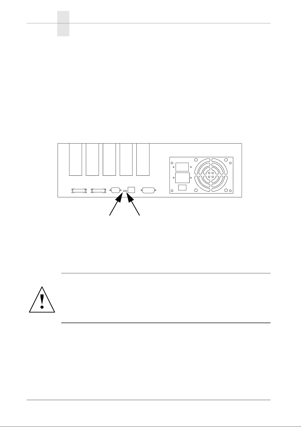
• Front-panel Ethernet LED
This LED indicates all Ethernet traffic to and from the MultiCom.
• Rear-panel Link LED
This LED indicates that the Ethernet connection is properly wired. The Link
detection is only possible on the 10-Base-T connector.
• Rear-panel Rx LED
This LED indicates all Ethernet traffic on the connected network.
Slot 1
Slot 2
Slot 3
Console EthernetSerial2Serial1
Slot 4
1.4.2
Slot 5
Link Rx
Figure 5 Rear-panel Ethernet LEDs
WARNING — Do not connect the MultiCom to an ISDN line with any
cable other than the one delivered with the MultiCom. Twisted pair Ethernet (10-Base-T) cables use the same RJ-45 connectors as ISDN but they
are not compatible. Using the wrong cable or connecting the ISDN port
to an Ethernet Hub may damage the MultiCom.
12 MultiCom LAN Access Center — User’s Manual
Page 15
CONNECTING THE ETHERNET NETWORK INSTALLATION FOR THIN ETHERNET
INSTALLATION FOR THIN ETHERNET
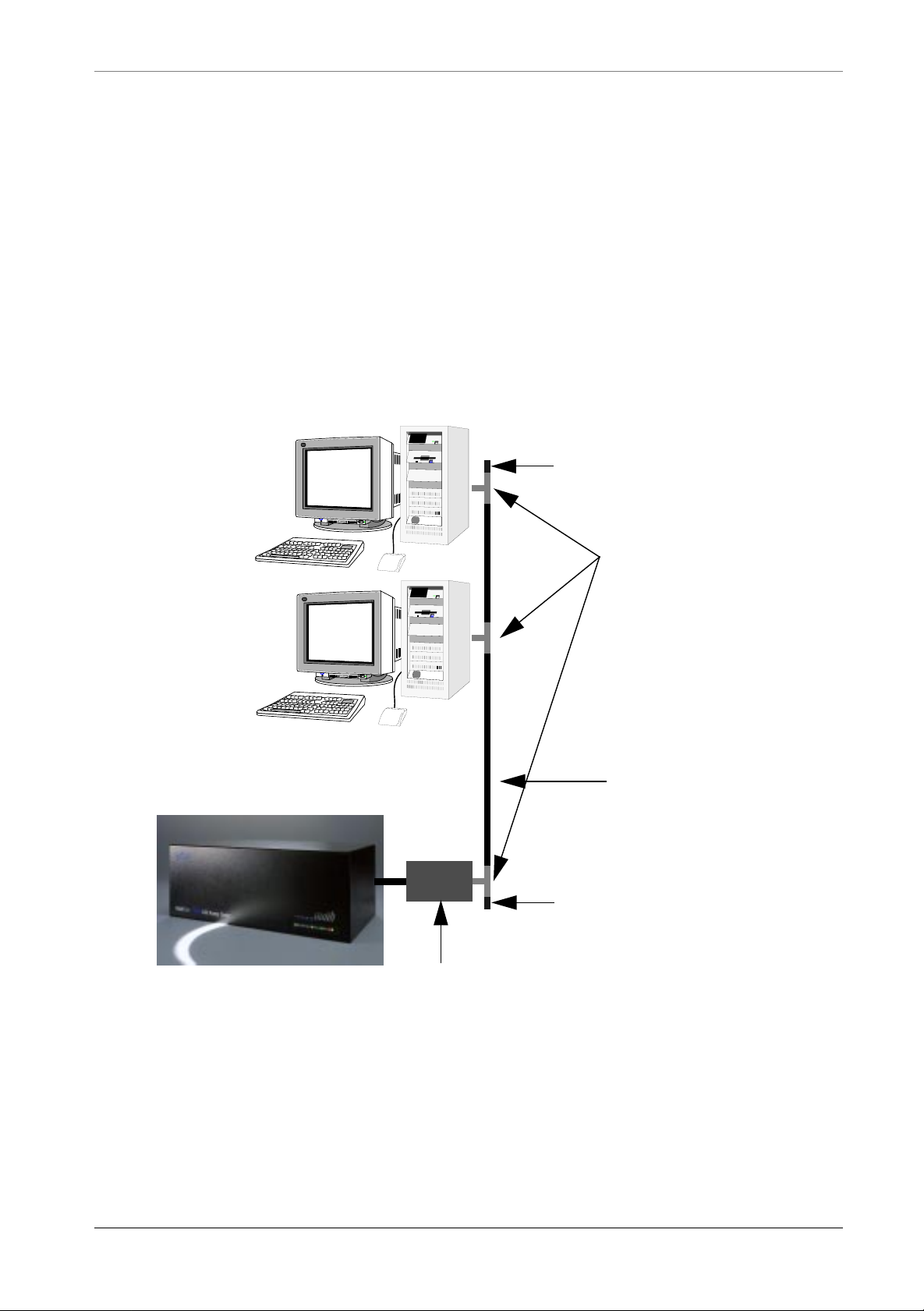
1. Make sure that your network is functioning without your MultiCom.
2. Plug a Thin Ethernet AUI adaptor into the AUI connector (as shown in Figure
4) of your MultiCom.
3. Connect a “T” connector to the AUI adaptor.
4. Open your network and connect both ends to the “T” connector.
50 Ohms termination
“T” Connectors
1.4.3
AUI adapter
Figure 6 Typical Thin Ethernet network
Standard 10-Base-2
Ethernet Cable (BNC)
50 Ohms termination
MultiCom LAN Access Center — User’s Manual 13
Page 16
CHAPTER 1INSTALLATION CONNECTING THE ETHERNET NETWORK
INSTALLATION FOR TWISTED-PAIR ETHERNET
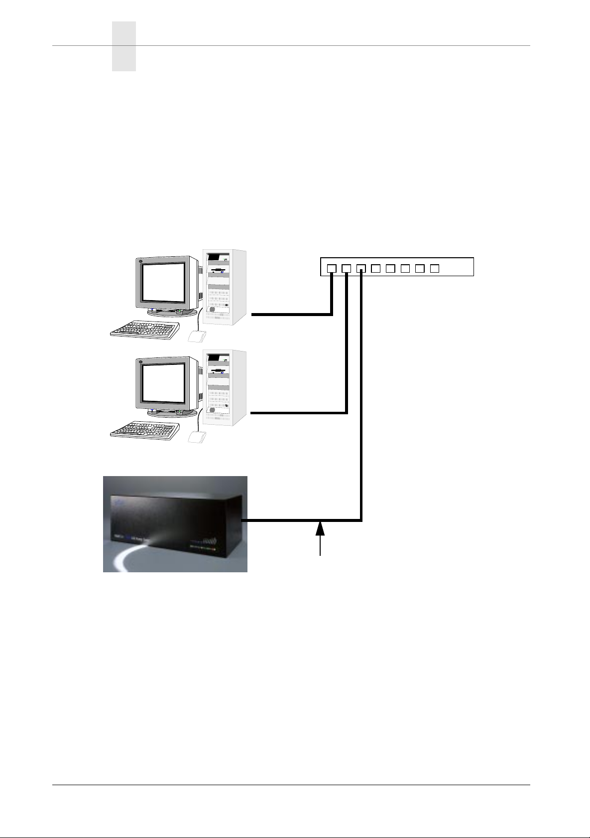
1. Make sure that your Ethernet Hub is functioning.
2. Plug the provided gray Ethernet cable into your Ethernet Hub.
3. Plug the other end into the RJ-45 connector on your MultiCom LAN Access
Center, as shown in Figure 4.
Ethernet Hub
HUB
1.4.4
Standard 10-Base-T
Ethernet Cable
Figure 7 Typical twisted-pair Ethernet network
14 MultiCom LAN Access Center — User’s Manual
Page 17
CONNECTING SERIAL DEVICES INSTALLATION FOR TWISTED-PAIR ETHERNET
CONNECTING SERIAL DEVICES
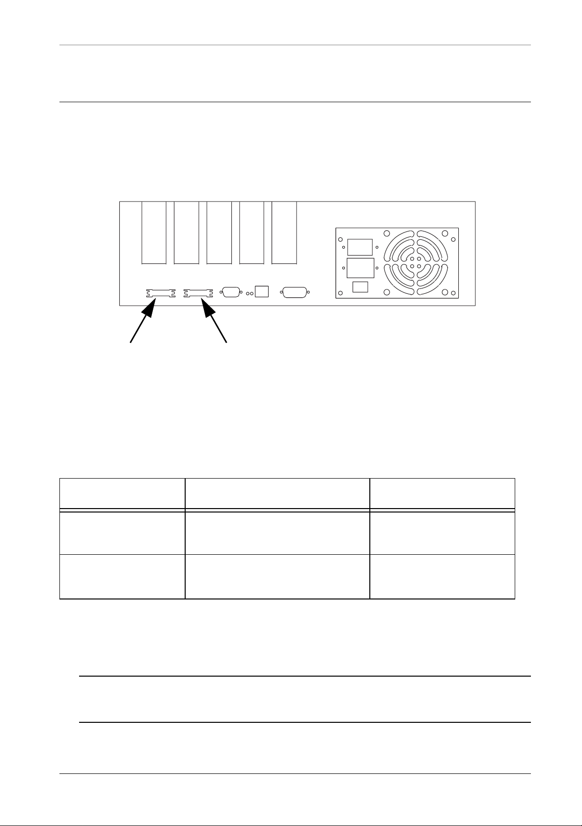
The serial ports are used for connecting your MultiCom to synchronous leased line
modems.
Slot 1
Figure 8 Serial port connectors
Slot 2
Slot 3
Console EthernetSerial2Serial1
Slot 4
Slot 5
1.5
The ports conforms to the EIA 530 Alt A standard. Lightning sells the following
adaptor cables for standard modem interfaces:
Table 6. Serial port cables
Reference Description Connector types
EIA 530 Alt A female
CBL-530F-V35M V.35 adaptor cable (2 meters)
<-> V.35 male
EIA 530 Alt A female
CBL-530F-X21M X.21 adaptor cable (2 meters)
<-> X.21 male
These cables are available through your distributor. Please be sure to order the
right cable, corresponding to your modem.
NOTE - Digital modems may require special cables. Contact Lightning’s Technical Support in that case.
MultiCom LAN Access Center — User’s Manual 15
Page 18
CHAPTER 1INSTALLATION CONNECTING PRI CARDS
CONNECTING PRI CARDS
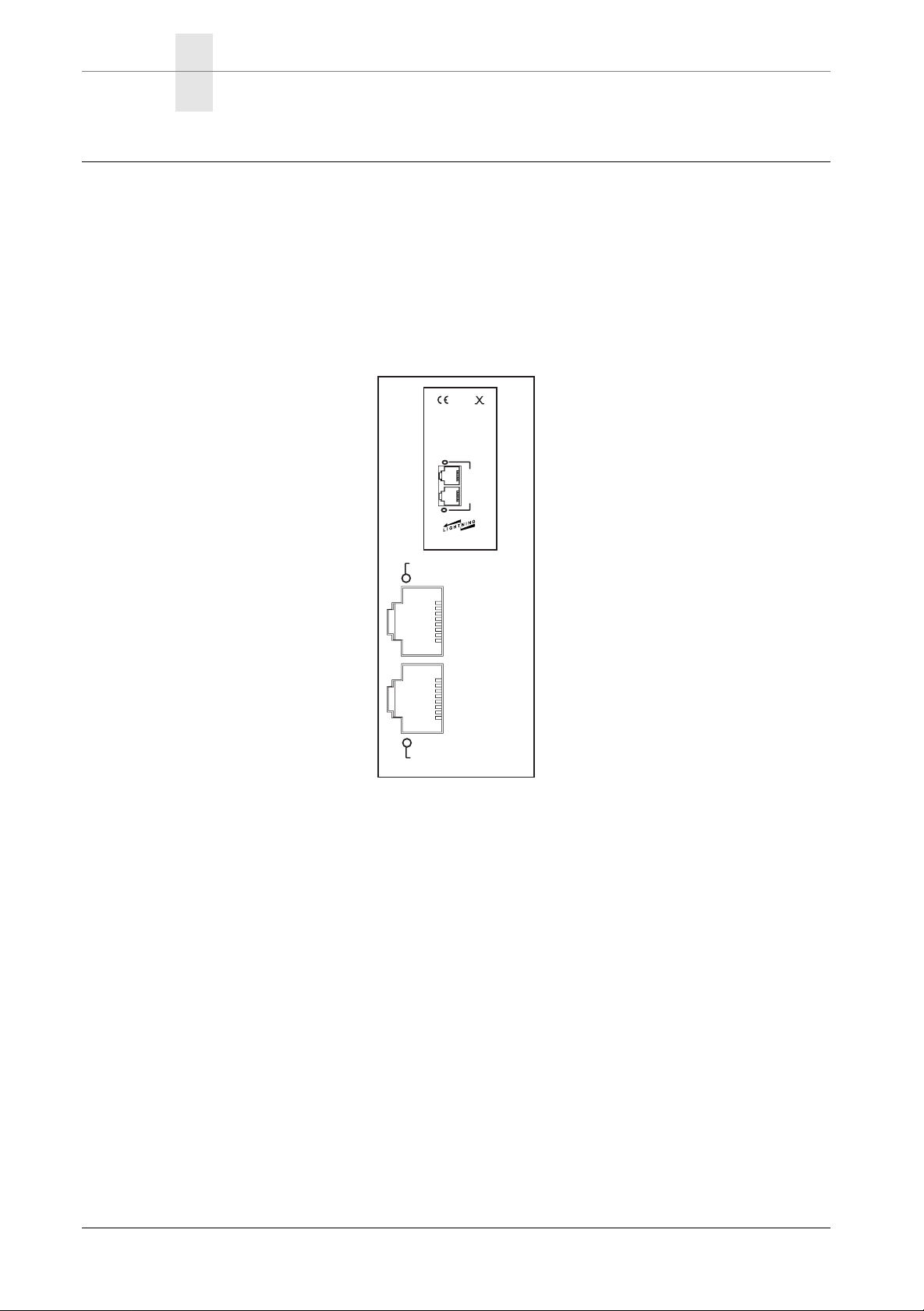
There are two RJ-45 connectors on the PRI card, as can be seen below. The lower
one is the ISDN S2m connector, the upper one is an auxiliary Ethernet port
(reserved for future use).
Approvals: BAKOM 97.0310.I.N
0188
Made in Switzerland, ©1997 by
LIGHTNING Instrumentation SA
CH-1010 Lausanne, Switzerland
Reference: LACxPRI
MultiCom
LAN Access Center™
Aux
Eth
Eth
Link
PRI
PRI
Link
Primary Rate ISDN
ETH
Link
Aux
ETH
1.6
1 Rx+
2 Rx–
PRI
PRI
Link
3 Shield
4 Tx+
5 Tx–
6 Shield
7 n.c.
8 n.c.
The PRI LED can be in the following four states:
• Red
This indicates that the ISDN link is not connected or not properly wired.
•Off
This indicates that the ISDN link has been disactivated by the remote switch.
This is rare but may happen with some switches. When needed, the link
should automatically be reactivated.
• Green
This indicates that the ISDN link is OK.
• Orange
This indicates that there is traffic on the D channel.
16 MultiCom LAN Access Center — User’s Manual
Page 19
CONNECTING PRI CARDS INSTALLATION FOR TWISTED-PAIR ETHERNET
Depending on your country, you may need a special adaptor cable to connect the
S2m to your local carrier. Please contact your local Distributor in that case.
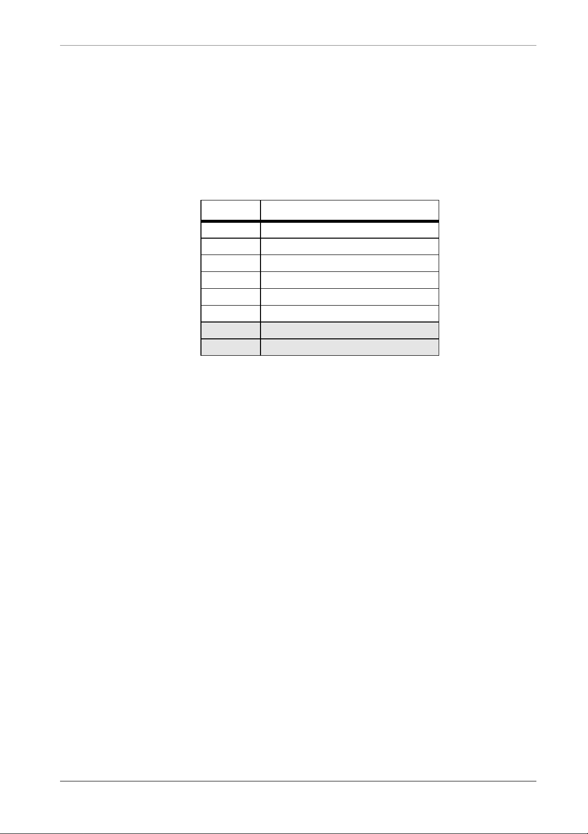
Here is the pin-out of the S2m RJ-45 connector:
Pin # Description
1 Rx 2 Rx+
3 Shield
4 Tx+
5 Tx 6 Shield
7 (not connected)
8 (not connected)
MultiCom LAN Access Center — User’s Manual 17
Page 20
CHAPTER 1INSTALLATION CONNECTING 4BRI CARDS
CONNECTING 4BRI CARDS
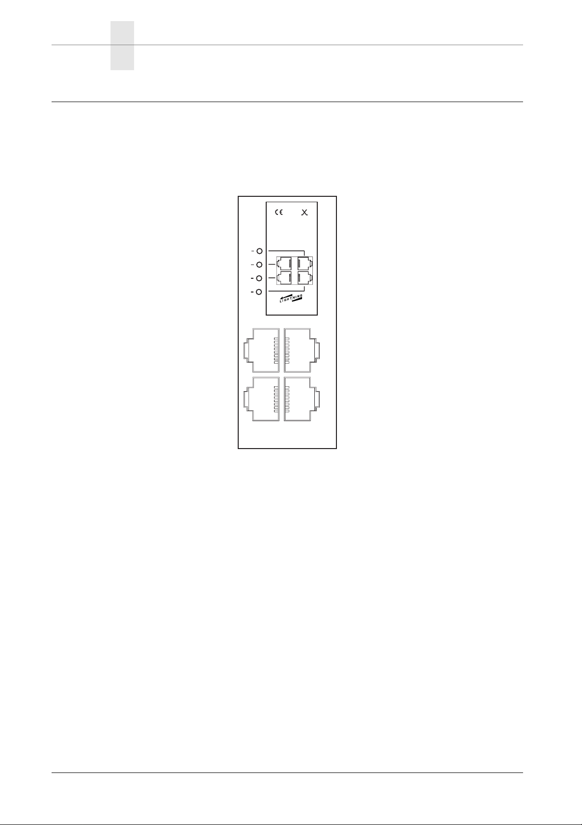
There are four RJ-45 S0 connectors on the 4BRI card, as can be seen below:
BAKOM 97.0309.I.N
0188
Made in Switzerland, ©1997 by
LIGHTNING Instrumentation SA
CH-1010 Lausanne, Switzerland
Reference: LACx4BRI
MultiCom
LAN Access Center™
D1
D2
D3
D4
BRI
BRI
2
1
BRI
BRI
3
4
Basic Rate ISDN TE
2
3
1
4
1.7
The BRI LEDs can be in the following four states:
• Red
This indicates that the ISDN link is not connected or not properly wired.
•Off
This indicates that the ISDN link has been disactivated by the remote switch.
When needed, the link should automatically be reactivated.
• Green
This indicates that the ISDN link is OK. It may become red after a certain
time. THIS IS NORMAL . It should become green again, as soon as you
need it.
• Orange
This indicates that there is traffic on the D channel.
18 MultiCom LAN Access Center — User’s Manual
Page 21
CONNECTING 4BRI CARDS INSTALLATION FOR TWISTED-PAIR ETHERNET
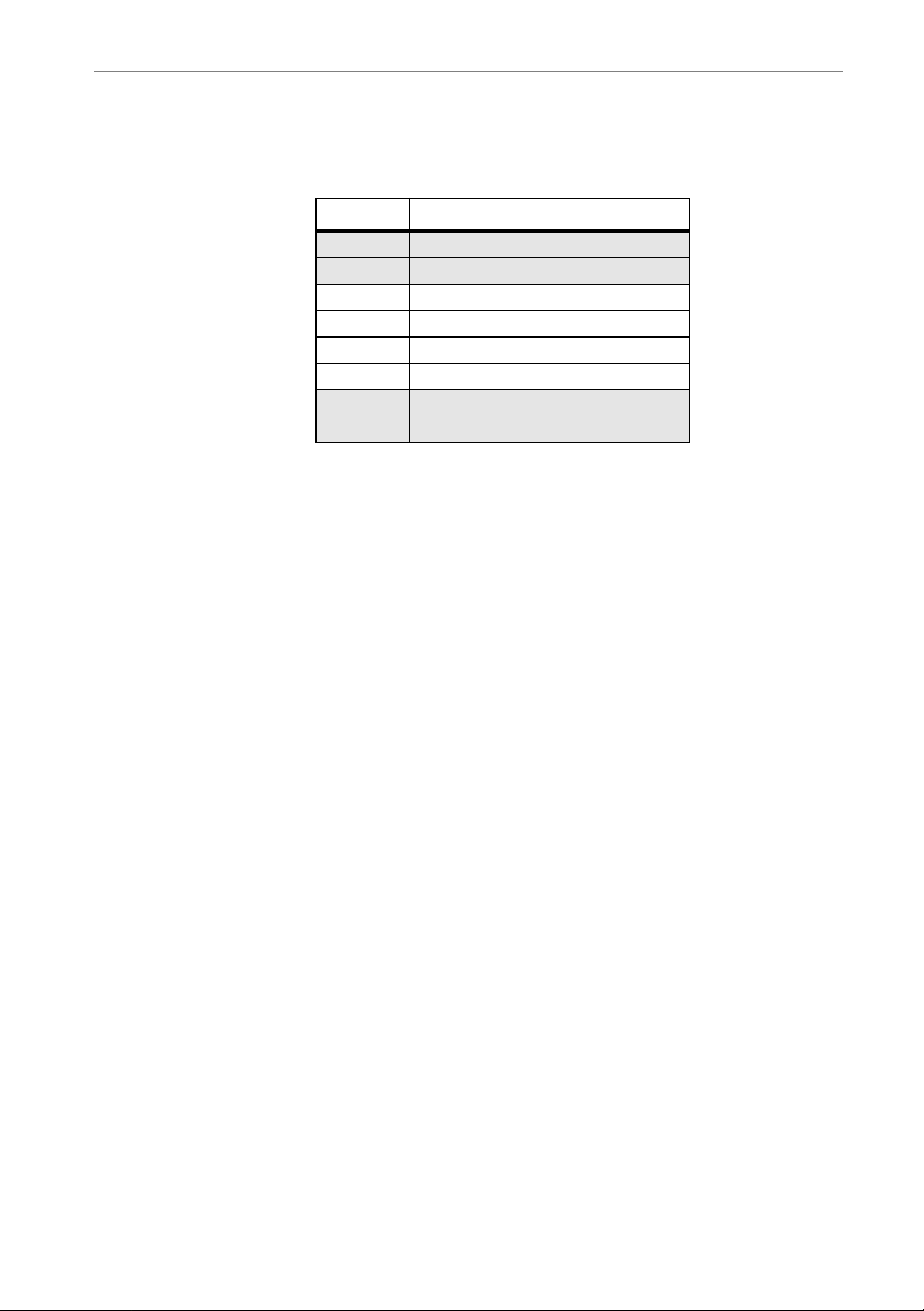
Here is the pin-out of an S0 RJ-45 connector:
Pin # Description
1 (not connected)
2 (not connected)
3 Tx+
4 Rx+
5 Rx 6 Tx 7 (not connected)
8 (not connected)
MultiCom LAN Access Center — User’s Manual 19
Page 22
CHAPTER 1INSTALLATION CONNECTING THE POWER CABLE
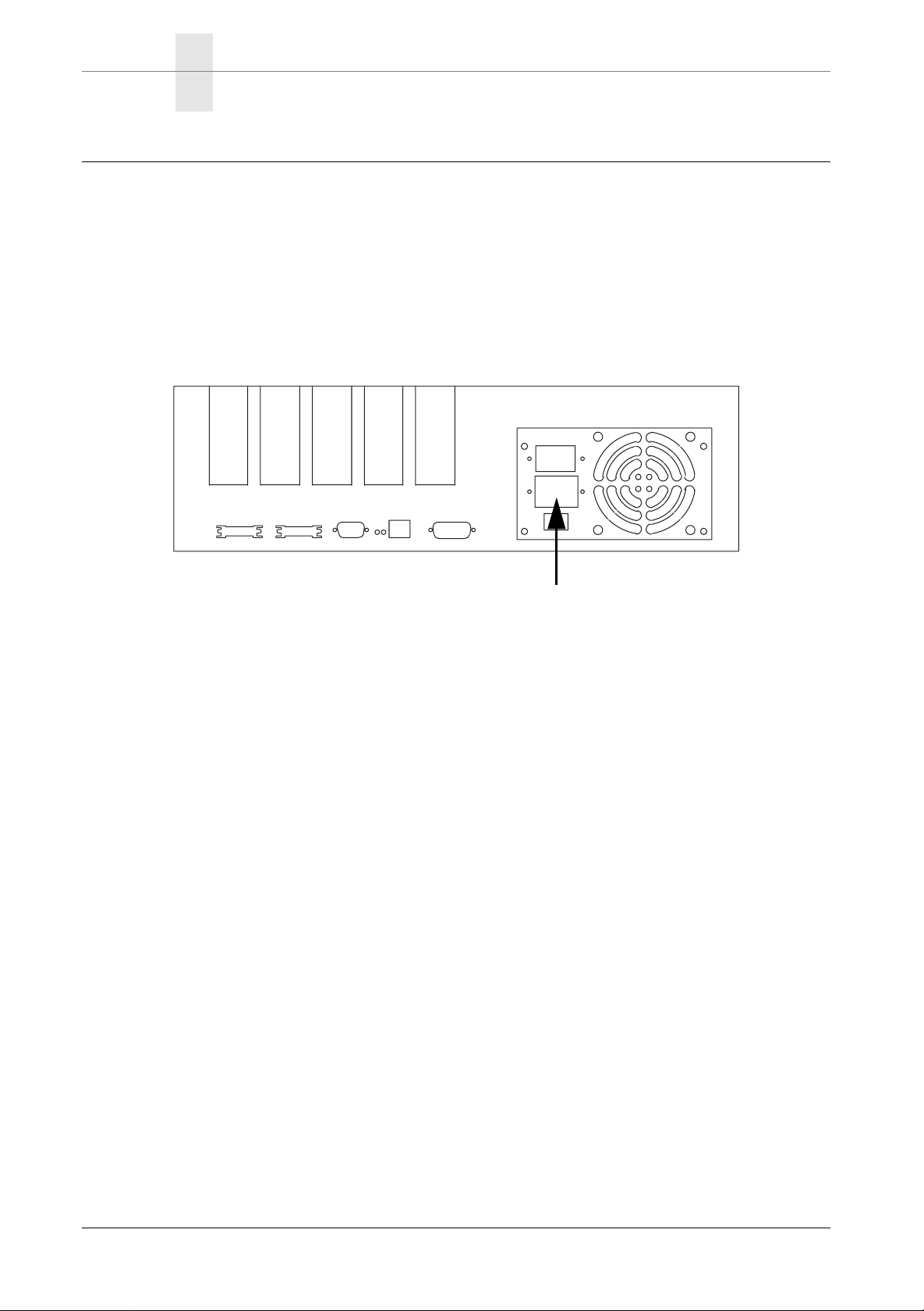
CONNECTING THE POWER CABLE
Connect the Power Cable to an AC wall socket and then to the power connector
on your MultiCom LAN Access Center
.
Slot 1
Slot 2
Slot 3
Console EthernetSerial2Serial1
Slot 4
Slot 5
Power connector
1.8
Figure 9 Power connector
This will launch the start-up operation for your MultiCom LAN Access Center,
described in the next paragraph.
20 MultiCom LAN Access Center — User’s Manual
Page 23
STARTING UP YOUR MultiCom INSTALLATION FOR TWISTED-PAIR ETHERNET
STARTING UP YOUR MultiCom
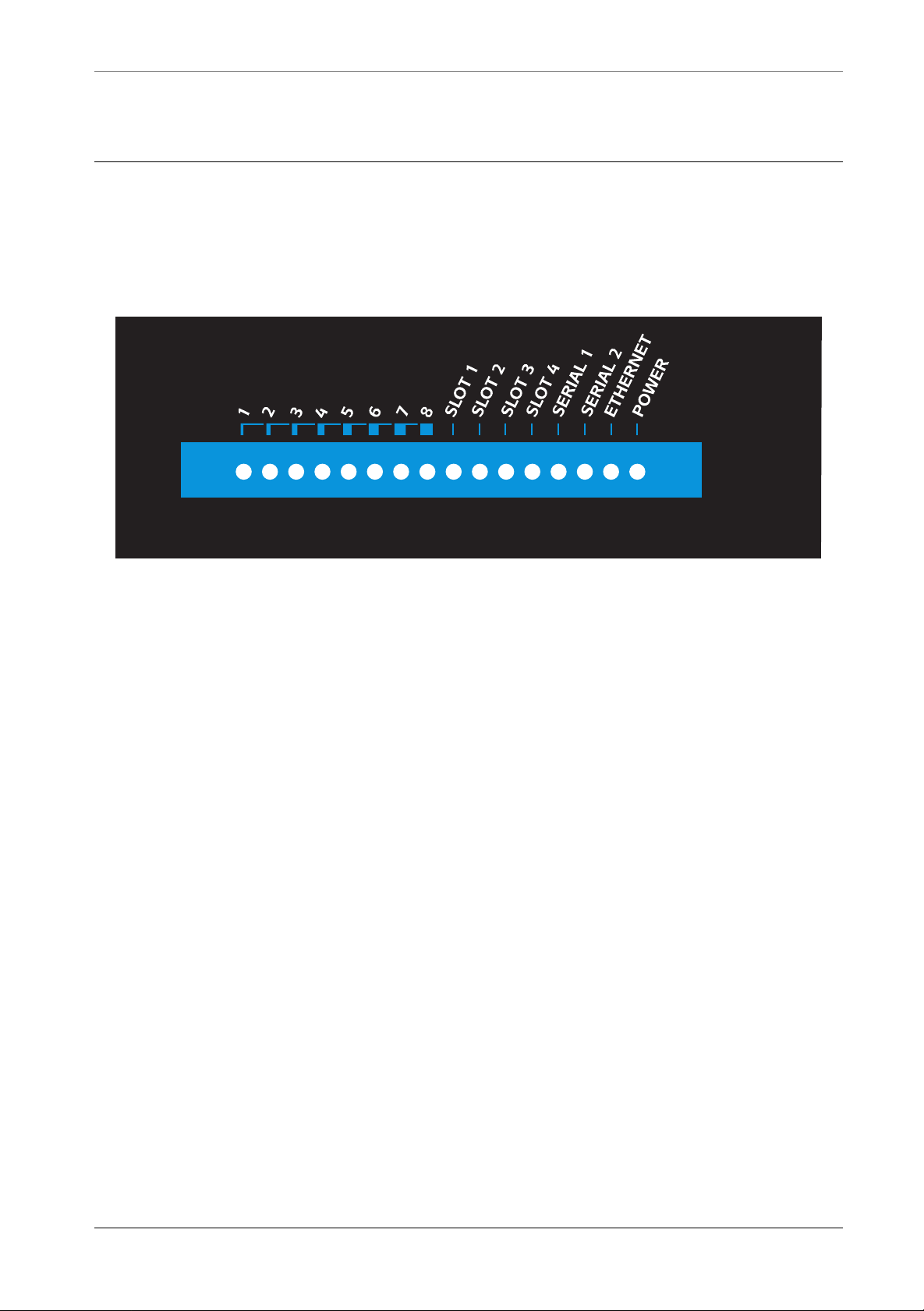
The MultiCom launches the start-up operation when you power it on. The following signals on the front panel provide information on the status of the operation:
• All LEDs become red, green and then orange
This is to test the LED display.
1.9
• The Power LED turns gr een while other LEDs tur n green and
red
This indicates that your
• The left LEDs (1..8) are blinking orange
This is the test for the default configuration (see section 4.3 on page 37).
• The slot LEDs turn green or off (depending on your configuration)
This indicates that the MultiCom has detected and initialized the corresponding optional expansion modules.
• The Ethernet LED turns green
This indicates that the Ethernet connection is properly wired.
• The Serial LEDs turn green (depending on your configuration)
If they are not used, they will remain of f. Otherwise they should turn green or
orange when there is traffic on the serial link. If they turn red, you should
check your serial configuration, your modems and your leased line.
MultiCom is carrying out system tests.
The other LEDs are reserved for future uses.
MultiCom LAN Access Center — User’s Manual 21
Page 24

CHAPTER 1INSTALLATION STARTING UP YOUR MultiCom
22 MultiCom LAN Access Center — User’s Manual
Page 25

Getting Started
This chapter describes the installation procedure
for your MultiCom in a few simple steps.
Chapter 2
2
Pocket MultiCom — User’s Manual 23
Page 26
CHAPTER 2GETTING STARTED DO NOT CONNECT TO A NETWORK BEFORE…
DO NOT CONNECT TO A NETWORK BEFORE…
Your MultiCom must be configured before being connected to an
existing Ethernet network . You may do it yourself or ask your dealer or
network specialist to configure it for you.
EASYCONFIG
The EasyConfig™ wizard takes your router's actual configuration, allows you to
modify it through some simple dialog boxes and saves the modified configuration
back into the router.
INSTALLING EASYCONFIG ON WINDOWS 95/98/NT
2.1
2.2
2.2.1
NOTE - EasyConfig runs also on Apple PowerMacintosh™ using the Windows
95/98 emulator “Virtual PC 2.1.2”™ (earlier versions are not fully compliant) by
Connectix™ Corp.
To install the EasyConfig wizard on your computer, execute the following operations:
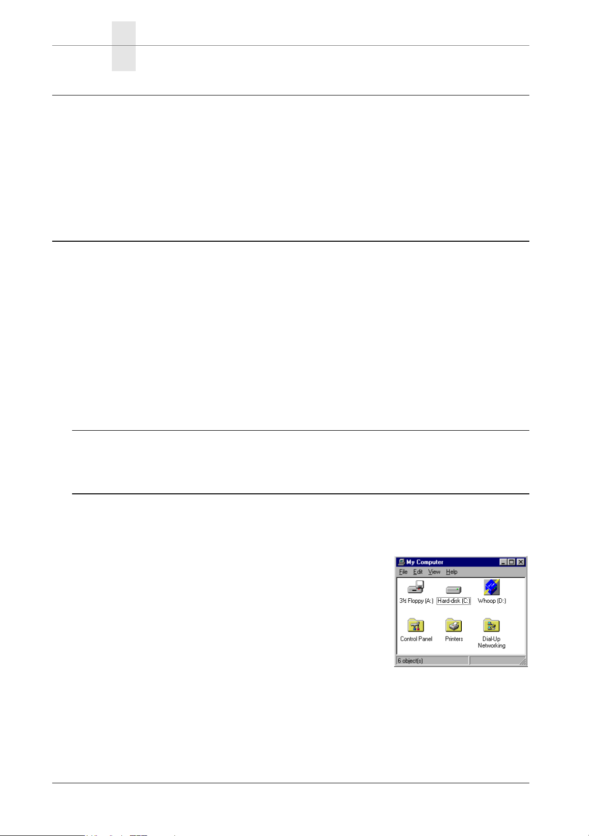
1. Insert the CD-ROM in your computer.
2. Your CD-ROM's content is displayed on the screen.
• If this doesn't happen so, open your CD by dou-
ble-clicking on “Desktop” and then on
“Whoop_2.5 (D:)”.
24 Pocket MultiCom — User’s Manual
Page 27
EASYCONFIG USING EASYCONFIG
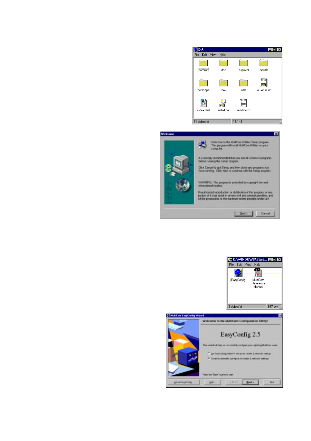
3. Double-click on the icon labelled install.bat in the root directory of the CD.
4. Then install the MultiCom
Utilities by following the
instructions. If possible, don't
modify the proposed values:
USING EASYCONFIG
1. Start the EasyConfig from the place it has been installed
in, by default:
“Start” / “Programs” / “MultiCom Utilities” /
“EasyConfig”.
2. Choose “I want to manually configure my router & network settings” and press on “Next”.
2.2.2
Pocket MultiCom — User’s Manual 25
Page 28
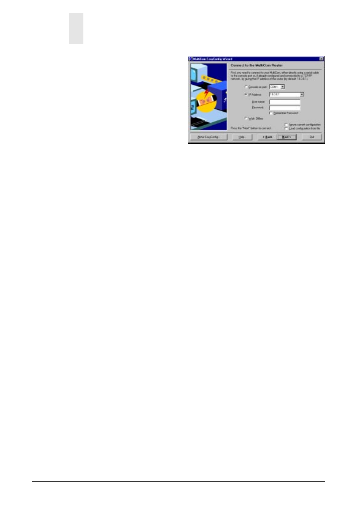
CHAPTER 2GETTING STARTED EASYCONFIG
3. If this hasn't been done yet, choose
the IP address 10.0.0.1 to communicate with the router.
4. Press on “Next”.
5. The EasyConfig wizard takes the
configuration from the router. By
clicking on “Next” you can see the
configuration step by step and
adapt it to your needs.
By clicking on “Help” you get help on the settings that you are currently editing.
USING EASYCONFIG TO SET STATIC IP ADDRESSING
On the CD-ROM, in the “doc” folder, you will find an Acrobat PDF file with a
short tutorial on using EasyConfig, and particularily an example on how to configure your Pocket MultiCom for static IP addressing.
USING EASYCONFIG WITH EXAMPLE CONFIGURATIONS
On the CD-ROM, you will also find in the “mcutils\Examples” folder all the
example configuration files (*.LCF) of the “Examples” chapter of the Reference
Manual. You may read these files, and adapt them for your own router setup using
EditConfig™, also part of the MultiCom Utilities, installed from the CD-ROM.
Please be advised that this requires some networking expertise and a good understanding of the examples, and associated commands explained in the Reference
Manual (on CD-ROM).
2.2.3
2.2.4
26 Pocket MultiCom — User’s Manual
Page 29

REFERENCE MANUAL, WEB, AND FAQ USING TELNET TO ACCESS THE COMMAND INTERFACE
REFERENCE MANUAL, WEB, AND FAQ
A detailed description of your router capabilities can be found in the Reference
Manual on the CD-ROM. A copy of this manual has been made on your hard disk
where the MultiCom Utilities EasyConfig and EditConfig have being installed.
Please also check the Technical Support area of our Web server at:
http://www.lightning.ch/support/
for future improvements in configuration, software, and the latest list of Frequently Asked Questions (FAQ). A short list of these can also be found in §3.
FINE-TUNING THE CONFIGURATION
For further configuration, you can use the router's built-in Web server at the
router's IP address (by default http://10.0.0.1/), or use the EditConfig™ Windows application, which both let you modify the configuration file generated by
EasyConfig.
2.3
2.4
CONNECTING TO THE COMMAND INTERFACE
For detailed control of the router, as well as interactive debugging and statistics,
you must use the Command Line Interface of your MultiCom. It can be reached
either through Telnet or with a direct console connection.
USING TELNET TO ACCESS THE COMMAND INTERFACE
If you MultiCom is correctly configured, you can run a Telnet program (e.g.
“C:\\WINDOWS\telnet”) to connect to it.
NOTE - By default your router has IP address 10.0.0.1
Pocket MultiCom — User’s Manual 27
2.5
2.5.1
Page 30

CHAPTER 2GETTING STARTED CONNECTING TO THE COMMAND INTERFACE
USING THE CONSOLE
To use the console, you need either a terminal or a computer with a terminal emulation software (this is included with most computers, like “Programs”/“Accessories”/“Hyper Terminal”™ with Windows™).
Once connected, your MultiCom displays its user interface on your terminal
screen. You can now auto-configure your MultiCom the commands “Upgrade
Key” (if needed) and “Setup”, or use EasyConfig with the “COM” port. You can
also reset the default configuration, as described in §4.
NOTE - If you see messages from the MultiCom in your terminal emulator window, but cannot type-in commands, check that the terminal handshake is set to
“XON/XOFF”, instead of “RTS/CTS” or “Hardware”.
2.5.2
28 Pocket MultiCom — User’s Manual
Page 31

Testing
This chapter provides instructions for checking
whether your MultiCom LAN Access Center is correctly configured and that the Ethernet and ISDN connections are working correctly.
3
Chapter 3
MultiCom LAN Access Center — User’s Manual 29
Page 32

CHAPTER 3TESTING FREQUENTLY ASKED QUESTIONS (FAQ)
FREQUENTLY ASKED QUESTIONS (FAQ)
Please also consult the Technical Support area of the Lightning web site at:
http://www.lightning.ch/support/ for an up-to-date list of the FAQ.
1. The IP address of the MultiCom is 10.0.0.1 by default.
2. Can I connect my MultiCom router to a Fast Ethernet network? Your MultiCom router is built for 10 Mbps Ethernet, thus it will not work if
connected to a 100 Mbps-only Ethernet port. Most Ethernet ports can do both
10 and 100 Mbps Ethernet. Your router will work if connected to such a port,
but only when using a 4-wires cable like the grey Ethernet cable delivered
with your router.
3. Which Stac compression do you support?
We support the standard Stac LZS® compression (RFC1974). We do not support the obsolete draft-09 version of Stac (sometimes called Stac-9) neither
Microsoft PPC (also know as MPPC or MS-Stac).
4. The ISDN line keeps up or opens periodically even if I don't access the Internet
3.1
There can be multiple causes for such a behaviour. First of all, make sure that
you have chosen a small timeout value for closing the line. The default value
is 90 seconds. If the line stays open longer than that, you may have an internal
problem (e.g. a misconfigured machine on your local network) or an external
problem (a misconfigured router talking to your
MultiCom). To find out where
the problem comes from, disconnect the Ethernet cable from the router and
check if the line still keeps up. If the line goes down after a few minutes, then
the problem is internal, if not then it is external. Use the command: Info
Site Internet Frames to check which IP packets are opening the line, and
Info Site Internet Frame
n
to display the most frequent one.
Common internal problems are:
• A mail program (e.g. Netscape, Eudora, MS Exchange) that is configured to
check mail every few minutes.
• A Web browser that has a starting page with an address that is outside your
network. Use a blank page or a local file as start page instead, e.g. file:/
mystartpage.html. Do not use an URL like http://localhost/mystartpage.html, as your computer will have to contact an external DNS server to
resolve the name “localhost”!
30 MultiCom LAN Access Center — User’s Manual
Page 33

FREQUENTLY ASKED QUESTIONS (FAQ)
• A Web page that updates automatically. Some Web pages, e.g. home pages,
live images, update themselves automatically and can keep the line open.
Don't keep a window with such a page open while you are not using it.
External problems may be:
• You are talking to a MaxPro RWS-NT V1.0.0.4 router. That router recognises "Echo Requests" as traffic and incorrectly keeps the line up. If you can
make sure that the router on the other end of the line is a MaxPro RWS-NT
V1.0.0.4, put the command "PPP EchoRequest Off" into the part of the configuration file relating to that site.
• If it is another external problem, try contacting the owner of the router at the
other end of the line and make sure that the router does not send unsolicited
traffic. Try setting the timeout to a small value e.g. by adding the following
command to your configuration file: "ISDN IdleCloseTime 10".
5. I cannot connect to Telia with AutoConfiguration, why?
Telia is using the private A-class IP range 10.0.0.0, which is a non-routable
subnet that is also used locally by the AutoConfiguration setup! To connect
anyway, you can manually change the generated configuration to use the private B-class 192.168.0.0 subnet with SubnetMask 255.255.0.0. Such a
configuration is given in the e xamples section of the Reference Manual on the
CD-ROM.
6. When I use the SecureWall function, sending mail is very slow, why?
Some external mailers check the source port #113 to verify the identity of the
sender. Since the SecureWall drops unsolicited incoming packets, the mailer
will experience a timeout before giving up and accepting the mail anyway. If
you are in that case, you can simply map this port to the MultiCom, which will
signal that the port is not reachable and cause the mailer not to wait. To do so
add the following line to your configuration or chose the equivalent option in
the EasyConfig wizard:
IP Translation Map 113/tcp To <IP address of your MultiCom>
7. The SecureWall prevents some types of FTP connections.
As with most firewalls, FTP transfers can only succeed if the FTP program is
set to passive mode for gets and active mode for puts (these are standard in
Internet Explorer, Netscape, pftp, CuteFTP and Fetch in firewall mode).
8. Is the MultiCom LAN Access Center Year 2000 compliant? Yes
MultiCom LAN Access Center — User’s Manual 31
Page 34
CHAPTER 3TESTING GENERAL TROUBLE-SHOOTING SCHEME
GENERAL TROUBLE-SHOOTING SCHEME
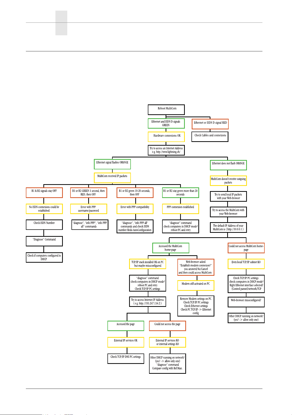
In case of connection problems, just looking at the signals behaviour can give
useful hints for finding your configuration problem. A general scheme, valid for
AutoConfiguration setting with DHCP and SIUA is shown below:
3.2
32 MultiCom LAN Access Center — User’s Manual
Page 35

CONNECTING TO A DISTANT SITE
CONNECTING TO A DISTANT SITE
Connecting to a distant site using Telnet, FTP, Ping, a Web browser, or your particular software is the quickest and easiest ways to ensure that your Ethernet and
ISDN connections are both functioning correctly:
If you could not connect, try connecting to another site to make sure that the problem does not reside on the other side of the line. If you can not connect on your
second attempt, carry out the following tests.
CHECKING THE ETHERNET CONNECTION
You can use either a Web-browser, Telnet, FTP or ping, specifying the IP address
of your MultiCom LAN Access Center, to connect to it directly. If the connection
opens, this confirms that your Ethernet software is working correctly.
3.3
3.4
If the connection does not open, make sure that you typed in the correct IP
address. If you did, there is probably a problem with either the configuration of
your MultiCom LAN Access Center or your computer. Refer to § 3.2, "General
Trouble-Shooting Scheme" on page 32 for details.
If you still can’t access your MultiCom LAN Access Center, you can reset it to factory default address 10.0.0.1 and DHCP mode by following section 4.3 on page
37.
CHECKING THE ISDN CONNECTION
Carry out the following test if your Ethernet connection is functioning correctly
but you cannot connect to a distant site:
1. Run Telnet or a console connection, specifying the IP address of your
MultiCom LAN Access Center, following instructions in section 1.3 on page 9.
3.5
MultiCom LAN Access Center — User’s Manual 33
Page 36
CHAPTER 3TESTING FURTHER TROUBLE-SHOOTING
2. The connection opens and asks for the user name and password, if set.
3. At the next prompt, type in the following command: ISDN Conn
A B-channel signal should turn green, indicating a successful connection.
If the ISDN connection is not OK, check the configuration of your MultiCom for
problems. Check also to see if there is a problem with your telephone wires.
If the ISDN connection is OK, but you still cannot connect to a distant site, it is
probably because there is either a problem with your computer’s configuration, or
with the configuration of the other site’s router or computer.
FURTHER TROUBLE-SHOOTING
Please refer to the Reference Manual for further trouble-shooting. Especially, try
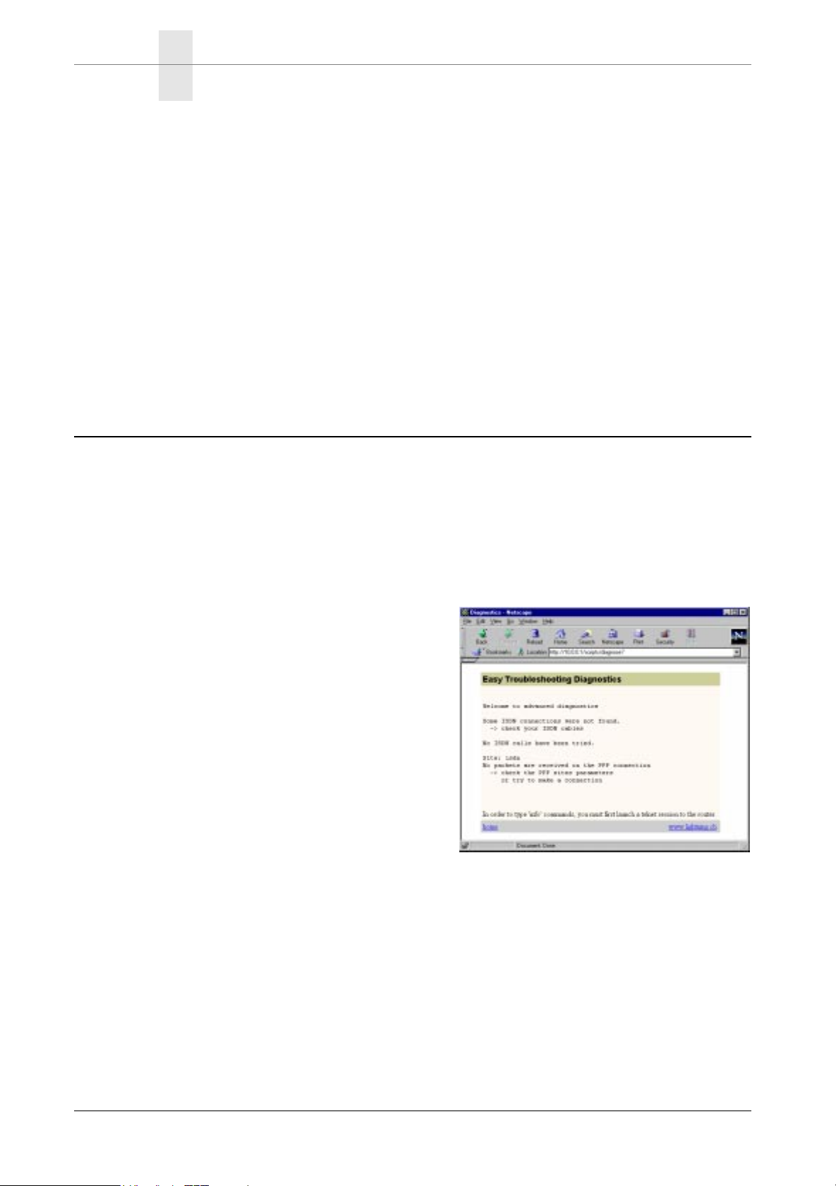
first the Diagnose command:
1. Run a Web-browser, specifying the IP address of your MultiCom.
2. The connection opens and asks for your user name and password, if set.
3. The MultiCom LAN Access Center home-page appears.
4. Click on the link: “Diagnostics”, corresponding to the Diagnose command.
5. You will receive basic diagnostics: Follow the suggestions provided.
6. You may need to run Telnet, specifying the IP address of your MultiCom
LAN Access Center, logging-in, and typing some “info” commands, like:
3.6
¥ isdn info ¥ isdn info history ¥ site stats Internet
¥ ppp info ¥ ppp info all ¥ site info internet frames
¥ dhcp info ¥ info ip ¥ site info internet frame
¥ dns info ¥ info ip router ¥ info site internet
¥ cat boot.rpt ¥ ip siteAddr info ¥ ip translation info
These commands and more are documented in the “Commands” chapter of
the Reference Manual on CD, including also a trouble-shooting chapter.
34 MultiCom LAN Access Center — User’s Manual
n
Page 37

Configuration
This chapter describes how to install your MultiCom
LAN Access Center in order to set the configuration
for the first time or to modify the existing configuration. It also provides instructions for resetting the
default configuration.
4
Chapter 4
MultiCom LAN Access Center — User’s Manual 35
Page 38

CHAPTER 4CONFIGURATION INSTALLING FOR CONFIGURATION
INSTALLING FOR CONFIGURATION
Configuring your MultiCom LAN Access Center for the first time can be done with a
direct console port connection or a direct Ethernet connection.
NOTE - For a direct connection, you need either a terminal or a computer with a
terminal emulation software (this is included with most computers). the serial port
of your computer must have a specific configuration, see Figure 3 on page 10 for
details.
Once the start-up process is finished, your MultiCom LAN Access Center will displays its user interface on your screen. You can now configure your MultiCom LAN
Access Center using the “EasyConfig” Windows wizard or manually, according to
the instructions in the “Configuration” section of the Reference Manual.
4.1
DEFAULT CONFIGURATION
When shipped, your MultiCom LAN Access Center has a default configuration file,
with the following informations set:
• IP address of the router: 10.0.0.1
• No User Account
• ISDN NumberEnabled: * (all)
• Site protocol: PPP
• Authentication: None
• DHCP server: On
This allows you to connect to your MultiCom without security checking, either
from Ethernet or the console, for local configuration, or from the ISDN connection, for remote configuration.
4.2
36 MultiCom LAN Access Center — User’s Manual
Page 39

RESETTING THE DEFAULT CONFIGURATION
CA UTION — All these parameters must be changed later to suit your
needs. In particular, it is strongly advised to create a user
account , for security reasons!
NOTE - You cannot access the private 10.0.0.1 address, unless you are in the
same IP subnet. You must either use the console to change it, change your own IP
address to be in the same subnet as your MultiCom, or configure your computer to
be a DHCP client.
RESETTING THE DEFAULT CONFIGURATION
If you want to return to a safe configuration or if you have forgotten your password, you can temporarily restart your MultiCom in its default configuration by
using the console:
1. Install your MultiCom LAN Access Center for a console connection, as
described in § 1.1, "Checking Your Package Contents" on page 8.
2. During the start-up operation — when all left LEDs are blinking orange
— press the minus key ( -) 10 times.
Upon initialization, your MultiCom LAN Access Center will be reset to the
default configuration.
You can then start a new configuration or upload a backup of the last working
configuration.
4.3
NOTE - For that reason, always keep a backup of your working configuration.
MultiCom LAN Access Center — User’s Manual 37
Page 40

CHAPTER 4CONFIGURATION RESETTING THE DEFAULT CONFIGURATION
To permanently reset your MultiCom L AN Access Center with the default configuration, follow the standard set of instructions for modifying configuration, as
described in the “Config” section of your Reference Manual.
NOTE - The user’s configuration file is not overwritten by this manipulation. It
will be available again the next time you reboot your MultiCom.
38 MultiCom LAN Access Center — User’s Manual
Page 41

Appendix 5
You will find here the Warranty Registration Card
(if you cannot use the on-line registration form)
and detailed technical information.
Chapter 5
MultiCom LAN Access Center — User’s Manual 39
Page 42

CHAPTER 5APPENDIX SPECIFICATIONS
SPECIFICATIONS
MULTICOM LAN ACCESS CENTER HARDWARE
Dimensions 44.4 x 13.3 x 24 cm
(19” x 3U)
Weight 6.8 kg
Power Requirements 230 VAC, max 3 A, 50 Hz
Temperature Ranges 5 to 40 °C
Humidity 10% to 85% non-condensing
Approvals EuroISDN
0188
LACx4BRI : BAKOM 97.0309.I.N (NET3)
LACxPRI : BAKOM 97.0310.I.N (NET5)
Pending for USA, Japan and Taiwan (ROC)
5.1
5.1.1
CONSOLE PORT
Connector EIA-574
Protocol Asynchronous RS-232
Speed 9600 bps
Number of Data Bits 8
Number of Stop Bits 1
Parity Bit No parity
Handshake None
Line Drivers RS-232, V.28
5.1.2
40 MultiCom LAN Access Center — User’s Manual
Page 43

SPECIFICATIONS ETHERNET PORTS
ETHERNET PORTS
Connectors AUI / 10-Base-T
Protocol IEEE 802.3
Speed 10 Mbits/s
SERIAL PORTS
Connectors EIA-530 Alt A
Protocol Synchronous (V.35 / V.36 / X.21)
Clock speed Up to 2 Mbits/s
ISDN (BRI)
5.1.3
5.1.4
5.1.5
Connectors FCC68 (EuroISDN RJ-45)
Protocol S0 TE DDI
Speed 2 x 64 Kbits/s
ISDN (PRI)
Connectors FCC68 (EuroISDN RJ-45)
Protocol S2m TE DDI
Speed 30 x 64 Kbits/s
5.1.6
MultiCom LAN Access Center — User’s Manual 41
Page 44

CHAPTER 5APPENDIX DECLARATION OF CONFORMITY
DECLARATION OF CONFORMITY
Conforms to EN45014 of the ISO/IEC
Manufacturer LIGHTNING Instrumentation SA
Address Avenue des Boveresses 50
CH-1010 Lausanne
Switzerland
declares that the products:
Name of Product LAN Access Center MultiCom
Reference Number LAC-IPIPXB and LAC-IPIPXB/E
and
Name of Product 4-BRI ISDN Interface module
5.2
Reference Number LACx4BRI
and
Name of Product PRI ISDN Interface module
Reference Number LACxPRI
conform all to the following specifications:
Security Norms IEC 950 / EN 60950
EN41003
EMC EN 55022 Class B / CISPR-22 Class B
EN 50082-1
French ISDN Deltas For VN4 ITAAB: Advisory NoteNumber
054 rev. 1
Commentary information none
Lausanne, Switzerland April 1997
42 MultiCom LAN Access Center — User’s Manual
Page 45

WARRANTY REGISTRATION CARD
The user (purchaser) must fill out and return this warranty registration card by
post or by fax within 10 days after the purchase date for activating your warranty
and/or update or upgrade. Upon receipt of this Registration Card, LIGHTNING
Instrumentation SA will register the product in the name of the purchaser.
Registered users will be notified when FREE UPDATES are available.
You can also register on-line at
http://www.lightning.ch/register.html
Name:___________________________________________________________
Job Title:_________________________________________________________
5.3
Company Name:___________________________________________________
Address: _________________________________________________________
Post Code/City: _____________________ Country: ______________________
Phone:_____________________________ Fax: __________________________
E-mail: __________________________________________________________
Product type: ______________________ Serial number: LI-MU2-CH- ______
Date of delivery
We would like to be kept aware of information (new products, upgrades) about
the MultiCom product range:
Please send this page (or a copy) by post or fax within 10 days of purchase to:
LIGHTNING Instrumentation SA
Avenue des Boveresses 50 Phone: + 41 21 654-2000
CH-1010 Lausanne Fax: + 41 21 654-2001
Switzerland E-mail: [email protected]
1
: ____________________ Supplier1:_____________________
❐ Yes ❐ No
1. In case of warranty repair, a proof of purchase with date may additionally be requested.
→→✂→→→✂→→→✂→→→✂→→→✂→→→✂→→→✂→→→✂
Page 46

3) Tape Together here on top only (no staples please)
1) Fill-in completely opposite side (you may also just register on-line or fax)
2) Cut page and Fold in two here 4) stamp appropriately and ship
WARRANTY REGISTRATION
LIGHTNING Instrumentation SA
Sales Department
Avenue des Boveresses 50
CH-1010 Lausanne
Switzerland
 Loading...