

Page 1

©
OWNER'S MANUAL
SERIES 1000
MODEL MT 1211
MEDIUM DUTY
BELT DRIVEN TROLLEY OPERATOR
The Chamberlain Group, Inc.
A DUCHOSSOIS ENTERPRISE
845 Larch Avenue
Elmhurst, Illinois 60126
3 2 1
Serial #
(located on electrical box cover)
Installation Date
Wiring Type
®
COMMERCIAL DOOR OPERATOR
LISTED
®
NOT FOR RESIDENTIAL USE
Page 2

SPECIFICATIONS
MOTOR
TYPE:................................Permanent Split Capacitor
HORSEPOWER:...............1/2 HP Intermittent Duty
(12 Cycles/Hr.)
SPEED: .............................1000 RPM
VOLTAGE:........................115VAC 60Hz Single Phase
CURRENT:........................6.0/6.5 AMP
MAXIMUM
DOOR SIZE:......................14' X 14'
MECHANICAL
DRIVE REDUCTION:
1st Reduction:..................Heavy Duty (4L) V-Belt
2nd & 3rd Reductions:.....#48 Chain and Sprockets
Output:.............................. #48 Chain
OUTPUT SHAFT SPEED:...85 R.P.M.
DOOR SPEED:....................8" - 10" per sec.
BEARINGS:.........................Heavy Duty Oil-Filled Bronze
BRAKE:...............................Solenoid Drum Brake
(Optional)
ELECTRICAL
TRANSFORMER: ..........24VAC
CAPACITOR:.................Single 70 microfared
CONTROL STATION:....3 Button
OPEN/CLOSE/STOP, NEMA 1
WIRING TYPE:...............B2 (Standard)
Momentary Contact to OPEN/CLOSE/STOP plus
Wiring for Sensing Device to Reverse and Auxiliary
Devices to Open and Close with Opener Override
LIMIT ADJUST:..............Linear Driven, Fully
Adjustable Screw Type Cams. Adjustable to 14 feet.
SAFETY
DISCONNECT:..................Spring Loaded Trolley
Disconnect Arm
CLUTCH:...........................Adjustable Friction Type
SAFETY EDGE:................(Optional)
Electric or Pneumatic Sensing Device attached to the
Bottom Edge of Door.
A REVERSING EDGE IS STRONGLY
RECOMMENDED FOR
OPERATOR INSTALLATIONS.
THE 3 BUTTON CONTROL STATION IS OUT OF
SIGHT OF DOOR OR ANY OTHER CONTROL
(AUTOMATIC OR MANUAL) IS USED. SEE PAGE 8.
ALL
COMMERCIAL
REQUIRED
WHEN
WEIGHTS AND DIMENSIONS
HANGING WEIGHT.....42 LBS.
DOOR HEIGHT + 3' - 3 1/2"
11 1/2"
HOW TO ORDER REPAIR PARTS
OUR LARGE SERVICE ORGANIZATION
SPANS AMERICA
INSTALLATION AND SERVICE INFORMATION
ARE AVAILABLE 6 DAYS A WEEK
CALL OUR TOLL FREE NUMBER - 1-800-528-6563
HOURS 7:00 TO 3:30 p.m. (Mountain Std. Time)
MONDAY Thorough SATURDAY
MIN. CLEARANCE
OF 2" FROM HIGH
ARC OF DOOR TO
BOTTOM OF TRACK
WHEN ORDERING REPAIR PARTS
PLEASE SUPPLY THE FOLLOWING INFORMATION
PART NUMBER DESCRIPTION MODEL NUMBER
ADDRESS ORDER TO:
THE CHAMBERLAIN GROUP, INC.
Electronic Parts & Service Dept.
2301 N. Forbes Blvd., Suite 104
Tucson, AZ 85745
2
Page 3

ASSEMBLE TRACK AND OPERATOR
CAUTION
THIS IS A MEDIUM USE OPERATOR, NOT
INTENDED FOR RESIDENTIAL OR HIGH USE
APPLICATIONS. TO PREVENT ELECTRICAL
COMPONENT DAMAGE AND RELATED POTENTIAL
HAZARD, DO NOT EXCEED TWELVE (12) CYCLES
PER HOUR.
DO NOT CONNECT ELECTRIC POWER UNTIL
INSTRUCTED TO DO SO.
FIGURE 1
Track
WARNING
KEEP DOOR BALANCED. STICKING OR BINDING
DOORS MUST BE REPAIRED. DOORS, DOOR
SPRINGS, CABLES, PULLEYS, BRACKETS AND
THEIR HARDWARE MAY BE UNDER EXTREME
TENSION AND CAN CAUSE SERIOUS PERSONAL
INJURY OR DEATH. CALL A PROFESSIONAL DOOR
SERVICEMAN TO MOVE OR ADJUST DOOR
SPRINGS OR HARDWARE.
Idler Shaft
Bracket
Trolley
Header
Bracket
Track Idler
Shaft
3 2 1
Check the identification tag mounted on the electrical
box to be sure the voltage, phase and h.p. are
correct for your needs.
1. Fasten track to the operator frame. DO NOT
TIGHTEN BOLTS. See Figure 1.
2. Position the slide on the track. Attach track
spacer(s).
3. Position the idler shaft between tracks. Place track
bracket over tracks. There are two holes on each
side of bracket (Fig. 1).
Fasten track bracket to end of rail assembly.
Track
Spacer
REFER TO MASTER WIRING DIAGRAM ON PAGE
10. MAKE CONNECTION THROUGH THE 7/8" DIA.,
LABELED HOLE. CONNECT THE HOT WIRE TO L1
- THE NEUTRAL WIRE TO L2 - AND THE GROUND
WIRE TO THE GREEN CHASSIS GROUND
SCREW. DO NOT RUN CONTROL WIRES IN THE
SAME CONDUIT AS THE POWER WIRES.
4. Align track so that slide moves easily and does not
bind. Tighten all bolts.
5. Run chain around front and rear sprockets and
attach to slide assembly with master links. Adjust
chain only until excessive slack is removed. To
retain proper tension, tighten 3/8" lock nut.
3
Page 4

INSTALL OPERATOR
CAUTION: AT LEAST TWO PERSONS AND A STRONG, SAFE WORKING PLATFORM ARE REQUIRED
FOR THE INSTALLATION OF OPERATOR.
CAUTION
TO AVOID DAMAGE TO DOOR AND OPERATOR,
MAKE ALL DOOR LOCKS INOPERATIVE. SECURE
LOCK(S) IN "OPEN" POSITION.
IF THE DOOR LOCK NEEDS TO REMAIN
FUNCTIONAL, INSTALL AN INTERLOCK SWITCH.
DO NOT RUN THE OPERATOR BEFORE MAKING
LIMIT SWITCH ADJUSTMENTS.
FOR METAL BUILDINGS ONLY: A strong mounting
surface for the operator front header bracket is
needed. On the wall above the center stile, weld or
bolt a 2"x2"x1/4" piece of angle iron or another
suitable, heavy-duty material as shown in Figure 2.
6. Draw a vertical line on header (or reinforcement
material) above center stile of door.
7. Raise the door to its high arc point. Use a
carpenter's level to locate high arc point on wall
above door center stile as shown in Figure 3. Make
a horizontal line, intersecting the vertical centerline
mark.
FIGURE 2
Building
Support
2"x 2"x 1/4"
Angle Iron
Carpenter's
Level
Vertical
Centerline
Center
Stile
Header
Wall
High Arc
Point
FIGURE 4
FIGURE 3
Header
2" Header
Wall
Bracket
High Arc
Point of Door
FIGURE 3
FIGURE 2
8. Close the door and refer to Figure 4. Position
operator chassis on the floor with the bottom edge
of header bracket 2" above horizontal mark and
centered on vertical line. Mark mounting holes.
FOR METAL BUILDINGS: Drill 3/8" holes for
fastening bolts. FOR CONCRETE BUILDINGS: Drill
3/8" holes for anchor bolts, following manufacturer's
instructions.
NOTE: Be sure header bracket is level before
tightening the bolts.
4
Page 5

9. Raise operator straight up until the door can be
raised to the full open position. See Figure 5.
Temporarily secure to ceiling or rafters with rope
or other suitable means.
WARNING
FAILURE TO SUSPEND THE OPERATOR
SECURELY MAY RESULT IN SERIOUS PERSONAL
INJURY OR DEATH, AND/OR PROPERTY DAMAGE.
10. Raise door to full open position. Place a 2x4
board on top of leading edge of door. Lower
operator to rest on 2x4 board.
Make four hangers from 2"x2"x1/4" angle iron. IT IS
RECOMMENDED THAT RAIL BE CENTERSUPPORTED AS WELL. Bolt the operator into place.
COIL CORD (OPTIONAL)
REFER TO (A) IN ILLUSTRATION
Connect operator end of coil cord to junction box (not
supplied) fastened to the wall approximately half-way
up the door opening.
Electrician must hardwire the junction box to the
operator electrical box in accordance with local
codes.
REEL (OPTIONAL)
REFER TO (B) IN ILLUSTRATION
Take-up reel should be installed 12" above the top of
the door.
2"x2"x1/4"
Angle Iron
Door
Bracket
Building
Support
Trolley
Door
Arm
Wire 24V
Track
Spacer
Rope
Release
B
Hanger Angles
2"x2"x1/4"
A
Reversing
Edge
Center
Stile
FIGURE 5
Air Hose
Pneumatic Air Switch
Not Required or Supplied
When Electric Reversing
Edge is Used
5
Page 6

CONNECT OPERATOR TO POWER SUPPLY AND INSTALL CONTROL STATION
WARNING
DISCONNECT POWER AT THE FUSE BOX BEFORE
PROCEEDING.
OPERATOR MUST BE PROPERLY GROUNDED AND
CONNECTED IN ACCORDANCE WITH LOCAL
ELECTRICAL CODES. THE OPERATOR SHOULD BE
ON A SEPARATE FUSED LINE OF ADEQUATE
CAPACITY.
ALL ELECTRICAL CONNECTIONS MUST BE MADE
BY A QUALIFIED INDIVIDUAL.
INSTALL THE CONTROL STATION WHERE THE
DOOR IS VISIBLE, BUT AWAY FROM THE DOOR AND
ITS HARDWARE. IF CONTROL STATION CANNOT BE
INSTALLED WHERE DOOR IS VISIBLE, OR IF ANY
DEVICE OTHER THAN THE CONTROL STATION IS
USED TO ACTIVATE THE DOOR,
EDGE MUST
THE DOOR.
EDGE UNDER THESE CIRCUMSTANCES MAY
RESULT IN SERIOUS INJURY OR DEATH TO
PERSONS TRAPPED BENEATH THE DOOR.
BE INSTALLED ON THE BOTTOM OF
FAILURE TO INSTALL A REVERSING
WARNING
A REVERSING
CAUTION
CAUTION
TO AVOID DAMAGE TO DOOR AND OPERATOR,
MAKE ALL DOOR LOCKS INOPERATIVE. SECURE
LOCK(S) IN "OPEN" POSITION.
IF THE DOOR LOCK NEEDS TO REMAIN
FUNCTIONAL, INSTALL AN INTERLOCK SWITCH.
REFER TO MASTER WIRING DIAGRAM.
MAKE CONNECTION THROUGH THE 1-1/16" DIA. LABELED HOLE. DO NOT RUN CONTROL WIRES IN
THE SAME CONDUIT AS THE POWER WIRES.
11. Complete the electrical connections to operator
and control station (Refer to Control Connection
Diagram, Pg. 20). Fasten the control station to the
wall.
FASTEN THE WARNING NOTICE BESIDE OR
BELOW THE PUSH BUTTONS.
12. Apply power to operator. Press either the OPEN
or the CLOSE push button and observe direction
of trolley travel. Press the STOP button.
If trolley did not move in the correct direction,
check for improper wiring at control station or
between opener and control station.
If electrical problems persist, call our Toll Free
number (1-800-528-6563) for assistance.
DO NOT ALLOW TROLLEY TO OVERRUN FRONT
IDLER SPROCKET OR RUN INTO OPERATOR
HEAD. LIMIT SWITCHES MAY NOT BE IN THE
PROPER POSITIONS. (See Limit Adjustments).
Control Station
OPEN
Push
Buttons
CLOSE
STOP
WARNING
TO PREVENT ENTRAPMENT
DO NOT START DOOR DOWNWARD
UNLESS DOORWAY IS CLEAR
WARNING Notice
13. Operate push button so that the trolley moves
forward (toward close position). Press STOP
button when trolley is approximately 10" from
front wall.
CONNECT DOOR ARM AND BRACKET
CAUTION
REINFORCE CENTER STILE WITH A VERTICAL
BRACE. USE A PIECE OF ANGLE IRON THAT WILL
SPAN THE HEIGHT OF TOP PANEL. DO NOT CUT
HORIZONTAL STRUT.
14. With door CLOSED, snap door arm onto operator
trolley. Position door bracket against reinforced
center stile of top section of door. Make sure arm
is straight and centered on stile. Mark bracket
holes. Drill and fasten with 5/16" bolts.
NOTE 1: Choose a set of holes which aligns door
arm in a near vertical position.
NOTE 2: If door strut interferes with placement of
door bracket, position bracket below strut. DO
NOT CUT OR MODIFY STRUT.
Attach door arm to door bracket using 3/8"-16x1"
screw and lock nut.
Slide
Door Arm
Door
Bracket
Center Stile
Reinforcement
Brace
6
Page 7
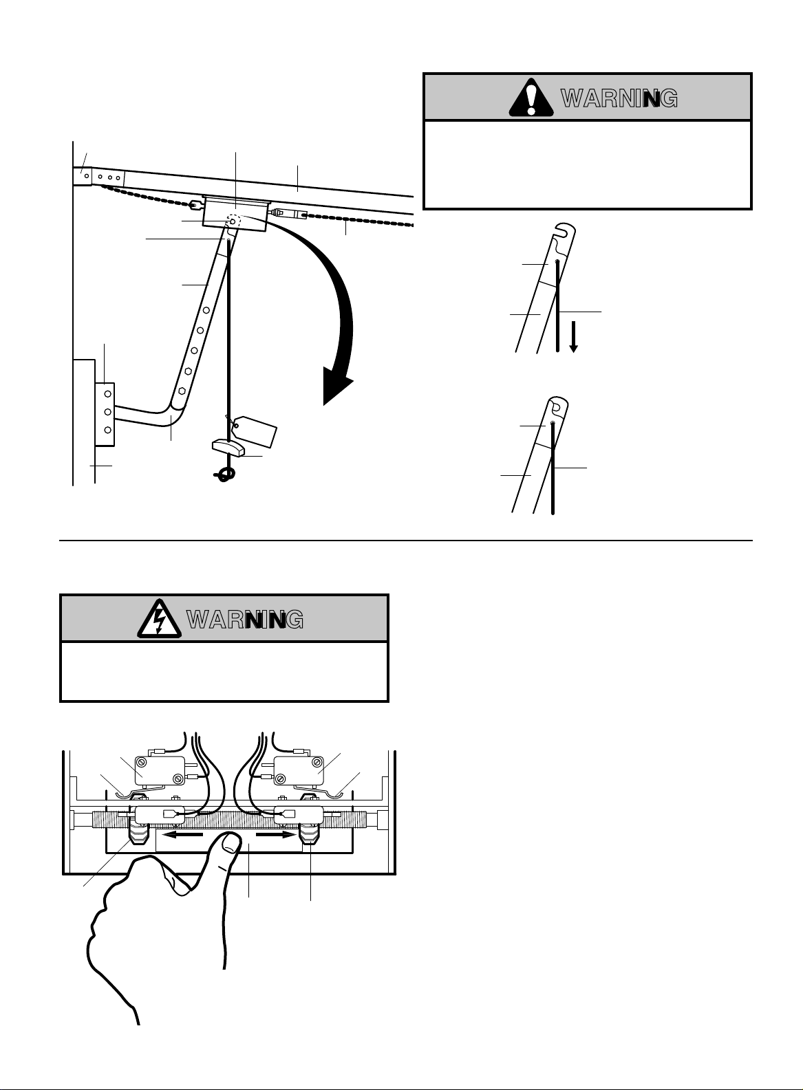
EMERGENCY DISCONNECT SYSTEM
WARNING
Header
Bracket
Emergency
Disconnect
Door
Bracket
12B0407
Door
Clevis
Pin
Straight
Door Arm
Assembly
1C3681
Curved
Door Arm
178B0045
Trolley
NOTICE
Track
Emergency
Release
Handle
Chain
DOOR ARM IS RELEASED FROM TROLLEY WHEN
EMERGENCY DISCONNECT OPENS.
TO AVOID BEING STRUCK BY DOOR ARM, DO NOT
STAND UNDER THE ROPE OR DOOR ARM WHEN
PULLING THE EMERGENCY RELEASE.
TO DISCONNECT
Emergency
Disconnect
DOOR FROM OPENER
Pull emergency
release handle
Door Arm
straight down.
Emergency
disconnect
will open.
TO RECONNECT
DOOR ARM TO TROLLEY
Emergency
Disconnect
Door Arm
Lift free end of
door arm to trolley.
Pull emergency handle
to allow arm to engage
clevis pin. Release
handle. Emergency
disconnect will close.
WARNING
TO AVOID SERIOUS PERSONAL INJURY OR DEATH
FROM ELECTROCUTION, DISCONNECT ELECTRIC
POWER BEFORE MANUALLY MOVING LIMIT NUTS.
Close Limit
Actuator
Close Limit
Nut
Switch
CLS
SLS
CLOSEOPEN
Travel Nut
Retainer
Open Limit
OLS
ADLS
Open Limit
Nut
ADJUST LIMITS
MAKE SURE THE LIMIT NUTS ARE POSITIONED
BETWEEN THE LIMIT SWITCH ACTUATORS
BEFORE PROCEEDING WITH ADJUSTMENTS.
1. Depress open limit switch. The operator should
stop.
Switch
Actuator
2. To increase door travel, spin nut away from
actuator. To decrease door travel, spin limit nut
toward actuator.
3. Adjust open limit nut so that door will stop in open
position with the bottom of the door even with top
of door opening.
4. Repeat Steps 1 and 2 for close cycle. Be sure
close limit actuator is engaged as door fully seats
at the floor.
If other problems persist, call our toll-free number for
assistance - 1-800-528-6563.
Press Travel Nut Retainer
Down Toward Frame
TO DISENGAGE.
7
Page 8

ADJUST CLUTCH
Adjust clutch so that it is tight enough to open and
close the door but will slip when the door meets an
obstruction. Either loosen or tighten the clutch nut
with 1/4 turn increments. The clutch will require
periodic inspection and adjustment.
CAUTION: The adjustable friction clutch is NOT
an automatic reversing device. An electric or
pneumatic reversing edge can be added to
bottom edge of door if desired.
CONNECT REVERSING EDGE DEVICE (OPTIONAL)
WARNING
IF CONTROL STATION CANNOT BE INSTALLED
WHERE DOOR IS VISIBLE, OR IF ANY DEVICE
OTHER THAN THE CONTROL STATION IS USED TO
ACTIVATE THE DOOR,
BE INSTALLED ON THE BOTTOM OF THE DOOR.
FAILURE TO INSTALL A REVERSING EDGE UNDER
THESE CIRCUMSTANCES MAY RESULT IN
SERIOUS PERSONAL INJURY OR DEATH TO
PERSONS TRAPPED BENEATH THE DOOR.
A REVERSING EDGE MUST
Clutch Pad
Clutch Plate
Jam Nut
Adjusting Nut
Spring
Washer
Clutch Pulley
The operator has been pre-wired to accept
connection of a reversing edge device (Figure 5,
Page 5). Connect the normally open contacts to
terminals T3 and T5 on the low voltage terminal
block. A cut-off switch will de-activate the safety
device during the last few inches of the door's
downward travel.
MAINTENANCE SCHEDULE
Check at the intervals listed in the following chart.
EVERY EVERY EVERY
ITEM PROCEDURE 3 MONTHS 6 MONTHS 12 MONTHS
Drive Chain Check for excessive slack.
Check & adjust as required.
Lubricate.*
Sprockets Check set screw tightness ●✔
Clutch Check & adjust as required ●✔
Belt Check condition & tension ●✔
Fasteners Check & tighten as required ●✔
Manual Disconnect Check & Operate ●✔
Bearings & Shafts Check for wear & lubricate ●✔
✳ Use SAE 30 Oil (Never use grease or silicone spray).
✔ Repeat ALL procedures.
■ Do not lubricate motor. Motor bearings are rated for continuous operation.
■ Do not lubricate clutch or V-belt.
●✔
■ Inspect and service whenever a malfunction is observed or suspected.
■ CAUTION: BEFORE SERVICING, ALWAYS DISCONNECT OPERATOR FROM POWER SUPPLY .
Page 9

Brake Drum
3/4" Washer
Key
3/4" Washer
Cotter
Pin
Cotter
Pin
A
Clutch
Pulley
Shaft
Spacer
Push Brake Lever
to Disengage Brake
Shoe Assembly
Brake Shoe
Assembly
5/16" x 5/8"
SEMS Screw
B
Brake Drum
5/16" x 5/8"
SEMS Screw
Nylon
Stud
Release
Spacer
Brake Drum
3
4
5
6
2
1
8
9
10
7
12
5
6
11
1A3989, 1A4045, 1A4046 & 1A4047
BRAKE INSTALLATION & ASSEMBLY PARTS
WARNING
TO AVOID SERIOUS PERSONAL INJURY OR DEATH
FROM ELECTROCUTION, DISCONNECT
ELECTRICAL POWER TO OPERATOR BEFORE
PROCEEDING.
1. Install brake drum on clutch pulley shaft as
illustrated in Fig. A.
2. Attach the four spacers provided to back of brake
pulley assembly housing using four 5/16 x 5/8
sems screws (Fig. B).
3. Push brake lever engaging nylon stud release
between brake shoes and align brake drum
between brake shoe assembly (Fig. B).
4. Adjust spring loaded bolt on brake shoe assembly
so that spring is compressed to 1".
5. Mount brake assembly housing to operator frame
using the four spacers and 5/16 x 3/8 sems screws
(See Fig. B).
6. Remove plug from 7/8" hole in electrical box and
attach conduit assembly.
7. Connect wires per master wiring diagram, (See
"brake optional").
8. Reconnect power to the operator.
9. Test for proper brake operation and replace brake
cover.
ADJUSTMENT: The brake assembly is selfadjusting and should not require further
adjustment.
KIT NO. DESCRIPTION
1A3989 115V Solenoid Brake, M - Series
1A4045 115V Solenoid Brake, H - Series & APT 2211
1A4046 230V Solenoid Brake, H - Series
1A4047 460V Solenoid Brake, H - Series
ITEM PART NO. DESCRIPTION & QUANTITY
1 17D111 Brake Box (1)
2 204B118 Solenoid 115V (1)
204B118-1 Solenoid 230V (1)
204B118-2 Solenoid 460V (1)
3 113B49 Brake Lever, Pivot (1)
4 179A46 Brake Release Stud
5 142A143 Brake Stud Plate (1)
REPAIR PARTS FOR BRAKE ASSEMBLY
ITEM PART NO. DESCRIPTION & QUANTITY
6 1B4421 Brake Shoe Assy. (2)
7 60B31 Brake Drum (1)
8 179B45 Brake Pivot Stud (3)
9 184A111 Brake Spacer (4)
10 1B3933 Conduit Assy. M-Series (1)
1B4044 Conduit Assy. H-Series (1)
11 31D387 Cover (1)
12 31A388 Dome Plug (1)
Page 10

MASTER WIRING DIAGRAM
RADIO
CONTROL
1
2
3
BROWN
GRY.
WHT.
YEL.
RED
VIOLET
GRAY/WHITE
ORANGE
YELLOW
YELLOW
VIOLET
BROWN
GRY./WHT.
VIOLET
VIOLET
10
11
RED
VIOLET
RED
ORANGE
GRAY/WHITE
YELLOW
VIOLET
BLACK
BLACK
BLACK
4
7
85 2
963
VIO.
WHITEWHITE
BRN.
GRY./WHT.
GRY./WHT.
ORG.
OPEN
LIMIT
C
AUXILARY
DEVICE
LIMIT
C
1
OPEN
RELAY
RED
RED
BLUE
YEL.
YEL.
NC
NO
YELLOW
NC
NO
GRY/WHT
MOTOR
CAPACITOR
BLACK
BLACK
VIOLET
RED
BLUE
BLACK
BROWN
WHITE
36 9
25 8
14 7
RED
WHITE
BLACK
RED
RED
RED
11
RED
YELLOW
VIOLETVIOLET
BRN.
BLK.
10
ORANGE
BRN.
BLACK
BLACK
CLOSE
RELAY
BLUE
YELLOW
NC
NO
NC
NO
CLOSE
LIMIT
C
SENSING
LIMIT
C
BLUE
YEL.
BLUE
ORANGE
WHITE
BLACK
BLACK
T
R
S
A
E
N
C
S
O
F
N
O
D
R
A
M
R
E
Y
R
L1
RED
P
R
I
M
A
R
Y
ORG.
BRAKE
(OPTIONAL)
RED
BLACK
BLACK
WHITE
L2
NEC CLASS 2
CIRCUIT
STANDARD
1
2345
Open
Close
Stop
REVERSE
SENSOR
AUXILARY
DEVICE
6
7
10
GROUND
NEUTRAL
HOT
GROUND
NEU.
HOT
GRD.
Page 11

MASTER SCHEMATIC
LIMITED DUTY C.D.O.
MASTER SCHEMATIC
NEUTRAL
RADIO
CONTROL
BLK.
HOT
GRD
L1
BLK.
2
5
BLK.
8
OPEN
3
9
BLK.
CLOSE
BRN.
3
BRN.
SENSING TO REVERSE
BRN. ORG.
6
STOP
4
1
OPEN
5
1
7
OPEN
BLK.
4
BLK.
BLK.
2
BRN.
RED
BLUE
VIO.
5
BRN.
BRAKE
(Optional)
SL
BRN.
VIO.
OPEN
11 10
O
8
CLOSE
BLK.
BLK. WHT.
WHT.
BLUE
ORN.
24 VAC
OL
VIO. YEL.
WHT.
L2
ORN.
YEL.
7
1
2
3
BROWN
GRY.
WHT.
YEL.
OPEN
BRN.
93
BRN.
OPEN/CLOSE
CLOSE
BROWN
CLOSE
6
RED
6
RED
VIO.
GRY./WHT.
ADL
VIO.
YEL.
6
7
4
WHITE
2
RED
YEL.
RED
CLOSE
10
RED
CL
11
C
11
Page 12

ILLUSTRATED PARTS – MT & MJ ELECTRICAL BOX
The Chamberlain Group, Inc.
CDO Electrical Box
CDO 91 Disk #1 (Yellow)
3/21/91 - 5/21/91
(parts renumbered 11-16-92)
13
12
7
6
5
4
3
14
2
1
11
8
10
4
9
3
5
CLOSE
2
OPEN
CONTROL
WIRING
NEC CLASS 2 CIRCUIT
3 2 1
3
15
1
6
17
16
16
18
7
12
Page 13

REPAIR PARTS – MT & MJ ELECTRICAL BOX
ITEM PT. NO. QTY DESCRIPTION
1 1D3695-1 1 Electrical Box Assy.
2 41K4303 1 Limit Bracket (ADJ) Kit
3 1B3796 1 Limit Shaft - Sprocket Assy.
4 133A182 2 Limit Nut
5 180B133 2 Limit Switch
6 41K4304 1 Switch Bracket Assy. (Aux. & Sensing)
7 216A191 1 Washer Spring Curved
8 1B3734 1 Transformer Assy.
9 30B432 1 Capacitor
10 12A461 1 Capacitor Bracket
11 160B69 2 Relay
12 1B3726 1 Terminal (2) Pos.
13 203B180 1 Terminal (7) Pos.
14 132A2012 1 Label
15 1B3727 1 Terminal Strip - 3 Pos.
16 216A184 2 Thrust Washer
17 11A12 1 Flange Brg, (3/8" I.D.)
18 158A49 1 Retaining Ring 3/8"
13
Page 14

ILLUSTRATED PARTS – OPERATOR MODEL MT 1211
23
ILLUSTRATED PARTS
9
OPERATOR MODEL MT 1211
8
11
20
10
15
14
8
21
13
19
22
9
7
8
16
12
15
6
18
3
17
4
OPEN
CLOSE
3 2 1
1
2
5
14
14
Page 15

REPAIR PARTS – MODEL MT 1211
ITEM
NO. PART NO. QTY DESCRIPTION
1 1 Electrical Box Assy. (See detail)
2 1A3797 1 Electrical Box Assy. Cover
3 123D114 1 Motor
4 31B413 1 Motor Cover
5 1A3742 1 Chain Assy. (43 Pitches)
6 81C151 1 Sprocket-Hub Assy. 13-3/4
7 See Chart 2 T-Rail
8 1B4001 1 Trolley Assy.
9 1C3992 1 1 Bracket Assy., #48 Chain
10 1C3692-2 1 Shaft Assy. - Pulley
11 See Chart Varies Spacer Kit
12 144C28 1 Pulley 6" - 4L
13 1C3688 1 Shaft Assy. - Intermediate
14 1C3689 1 Shaft Assy. - Output - #48
15 41K4301 1 Clutch Assy. Kit
16 20B8 1 V-Belt 34" - 4L
17 144B32 1 Motor Pulley w/Set Screw
18 59D48-6 1 Frame Right Side
59D48-7 1 Frame Left Side
19 184B97 4 Spacer
20
21 1A3741 2 Chain Assy. (41 Pitches) #48 Chain
22 41K4302 1 Header Brk. Assy.
23 41K4306 3 Oil Lite Brg. 3/4" I.D. Kit
RAIL - CHAIN ASSEMBLY - SPACER KIT
ITEM #7 ITEM #11
Door Chain #48 Chain 1 Set
Height Rail Qty Assembly Qty Master Link Qty Spacer Kit Qty
8 Ft. 183C135 2 1A3881 1 1A995 1 1A4004 2
10 183C135-1 2 1A3882 1 1A995 1 1A4004 2
12 183C135-2 2 1A3883 1 1A995 1 1A4004 2
14 183C135-3 2 1A3884 1 1A995 1 1A4004 3
for #48 Chain
15
Page 16

CONTROL CONNECTION DIAGRAM
®
ATTENTION: The 3-Button Control Station provided must be connected for operation
WIRING TYPE - B2
3 BUTTON STATION MULTIPLE 3 BUTTON STATIONS 3 BUTTON WITH ON/OFF SWITCH
T1 T2 T3 T4
STANDARD
• MOMENTARY CONTACT TO OPEN, CLOSE AND STOP
• ACCEPTS SENSING DEVICES TO REVERSE
• ACCEPTS AUXILLARY DEVICES TO OPEN AND CLOSE
• OPEN OVERRIDE
• SAME AS B2 EXCEPT CONSTANT CONTACT TO CLOSE. SEE BELOW.OPTIONAL C2
T1 T2 T3 T4
Open
Close
Stop
Open
Close Close
Stop Stop
Open
T1 T2 T3 T4
Open
Close
Stop
On/Off
OPEN / CLOSE DEVICE
T3 T6
ONE BUTTON STATION
PULL CORD
KEY SWITCH
ETC.
ATTENTION: ABOVE DEVICES WILL NOT FUNCTION WITHOUT A 3-BUTTON CONTROL STATION OR A
JUMPER BETWEEN T3 AND T4.
OPTIONAL C2 • CONSTANT CONTACT TO CLOSE
Remove white wire between terminal 2 of control
connection strip and terminal 4 of close relay. See
Master Wiring Diagram.
SENSING DEVICE TO REVERSE OPEN DEVICE
T3 T5
SENSING EDGE
PHOTO ELECTRIC CONTROL
ETC.
NOTE: INTERLOCKS, IF USED, SHOULD BE NORMALY
CLOSED AND PLACED IN SERIES BETWEEN
THE "STOP" BUTTON AND TERMINAL #4.
ONE BUTTON STATION
PULL CORD
KEY SWITCH
ETC.
T1 T3
© 1992, The Chamberlain Group
All Rights Reserved
Printed in Mexico114A1666A
 Loading...