

Page 1

MODELS LGO50113R, LGO50113L
LGO50113XR & LGO50113XL
LIGHT DUTY GRILL OPERATOR
OWNER’S MANUAL
Serial # Box
Installation Date
2 YEAR WARRANTY
NOT FOR RESIDENTIAL USE
LISTED DOOR OPERATOR
Page 2
2
When you see these Safety Symbols and Signal Words on the
following pages, they will alert you to the possibility of serious
injury or death if you do not comply with the warnings that
accompany them. The hazard may come from something
mechanical or from electric shock. Read the warnings carefully.
When you see this Signal Word on the following pages, it will
alert you to the possibility of damage to your door and/or the
door operator if you do not comply with the cautionary
statements that accompany it. Read them carefully.
Mechanical
Electrical
• BEFORE attempting to install, operate or maintain the
operator, you must read and fully understand this manual
and follow all safety instructions.
• These instructions are intended to highlight certain safety
related issues. These instructions are not intended to be
comprehensive. Because each application is unique, it is the
responsibility of the purchaser, designer, installer and end
user to ensure that the total door system is safe for its
intended use.
TABLE OF CONTENTS
WARNING
WARNING
WARNING
WARNING
CAUTION
WARNING
WARNING
WARNING
WARNING
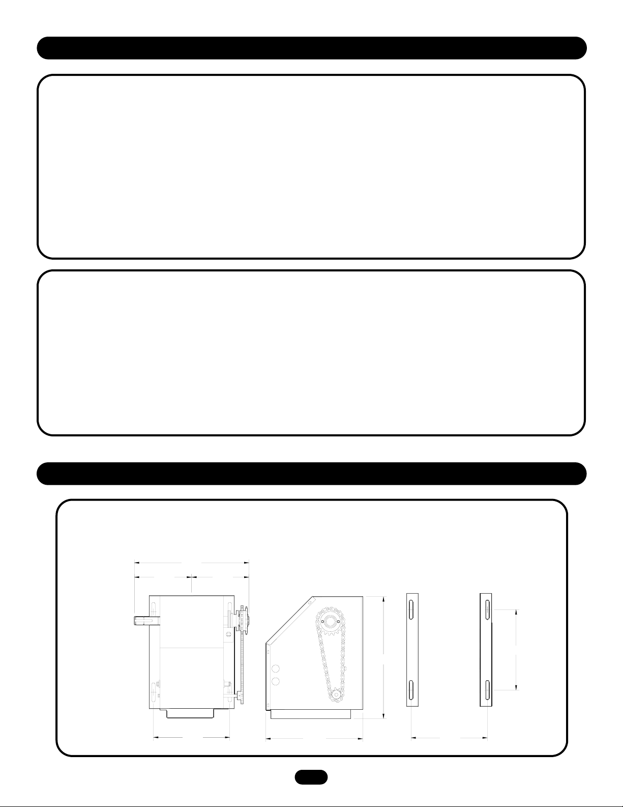
SPECIFICATIONS
Operator Specifications . . . . . . . . . . . . . . . . . . . . . . . . . . . . . . . .3
Operator Dimensions . . . . . . . . . . . . . . . . . . . . . . . . . . . . . . . . . .3
PREPARATION
Operator Preparation . . . . . . . . . . . . . . . . . . . . . . . . . . . . . . . . . .4
INSTALLATION
Operator Mounting . . . . . . . . . . . . . . . . . . . . . . . . . . . . . . . . . . . .5
Manual Operation . . . . . . . . . . . . . . . . . . . . . . . . . . . . . . . . . . . . .6
Door Operator System Illustration . . . . . . . . . . . . . . . . . . . . . . . .6
POWER & GROUND WIRING
Safety Warnings . . . . . . . . . . . . . . . . . . . . . . . . . . . . . . . . . . . . . .7
Three Prong Grounding Plug . . . . . . . . . . . . . . . . . . . . . . . . . . . .7
Permanent Wiring . . . . . . . . . . . . . . . . . . . . . . . . . . . . . . . . . . . .7
INSTALLATION OF DOOR CONTROLS
Three Button Station . . . . . . . . . . . . . . . . . . . . . . . . . . . . . . . . . . .8
Two Button/Two Position Key Switch . . . . . . . . . . . . . . . . . . . . . .8
PROGRAMMING OPERATING MODES
To Change Operating Modes . . . . . . . . . . . . . . . . . . . . . . . . . . . .9
ENTRAPMENT PROTECTION ACCESSORIES
Photo Eyes and Sensing Edges . . . . . . . . . . . . . . . . . . . . . . . . . .9
Connection Procedure . . . . . . . . . . . . . . . . . . . . . . . . . . . . . . . .10
ADJUSTMENTS
Limit Switch Adjustment . . . . . . . . . . . . . . . . . . . . . . . . . . . . . .11
Force Adjustment . . . . . . . . . . . . . . . . . . . . . . . . . . . . . . . . . . . .11
WIRING DIAGRAM
. . . . . . . . . . . . . . . . . . . . . . . . . . . . . . .12
TROUBLESHOOTING
Testing the Operator . . . . . . . . . . . . . . . . . . . . . . . . . . . . . . . . . .13
Troubleshooting Guide . . . . . . . . . . . . . . . . . . . . . . . . . . . . . . . .13
MAINTENANCE
Maintenance schedule . . . . . . . . . . . . . . . . . . . . . . . . . . . . . . . .14
CONTROL CONNECTIONS
Three Button Station . . . . . . . . . . . . . . . . . . . . . . . . . . . . . . . . .14
Two Button Station . . . . . . . . . . . . . . . . . . . . . . . . . . . . . . . . . . .14
Sensing Devices . . . . . . . . . . . . . . . . . . . . . . . . . . . . . . . . . . . . .14
ILLUSTRATED PARTS
Model LGO Parts . . . . . . . . . . . . . . . . . . . . . . . . . . . . . . . . . . . .15
Repair Parts Kits . . . . . . . . . . . . . . . . . . . . . . . . . . . . . . . . . . . .16
WARRANTY POLICY
. . . . . . . . . . . . . . . . . . . . . . . . . . . . . .17
OPERATOR NOTES
. . . . . . . . . . . . . . . . . . . . . . . . . . . . .18-19
REPAIR PARTS & SERVICE
. . . . . . . . . . . . . . . . . . . . . . .20
Page 3
3
9.45"
11.42"
9.00"
14.31"
9.00"
6.75"
6.75"
13.5"
SAFETY
DISCONNECT: Floor level disconnect for emergency manual
door operation.
PHOTO EYES: Photo eyes to reverse door.
NOTE: LIFTMASTER PHOTO EYES P/N CPS-LN4 ARE
STRONGLY RECOMMENDED FOR ALL COMMERCIAL
OPERATOR INSTALLATIONS. REQUIRED WHEN ANY OTHER
CONTROL (AUTOMATIC OR MANUAL) IS USED.
MOTOR
TYPE: . . . . . . . . . . . . . . . . . . . . . . . . . . . . . . . Intermittent Duty
HORSEPOWER: . . . . . . . . . . . . . . . . . . . . . . . . 1/2 Horsepower
SPEED: . . . . . . . . . . . . . . . . . . . . . . . . . . . . . . . . . . . 1600 RPM
VOLTAGE: . . . . . . . . . . . . . . . . . . . . . . . . . 115V, 1 Phase, 60Hz
CURRENT: . . . . . . . . . . . . . . . . . . . . . . . . See Motor Nameplate
WEIGHTS AND DIMENSIONS
HANGING WEIGHT: 40-45 LBS.
ELECTRICAL
CONTROL STATION: NEMA 1 three button station.
OPEN/CLOSE/STOP or 2 button station OPEN/CLOSE.
RADIO: The internal radio receiver will not operate in D1
(constant pressure mode)
WIRING TYPES: B2 (Standard) Momentary contact to open,
close and stop, plus wiring for sensing device to reverse and
auxiliary devices to open and close with open override.
D1 (Optional) Constant pressure to open and close with wiring
for sensing devices to stop.
LIMIT ADJUST: Linear driven, fully adjustable screw type cams.
Adjustable to 24 feet.
MECHANICAL
DRIVE REDUCTION:
Primary: . . . . . . . . . . . . . . . . . . . . . . . . . . . .Worm Gear 16:1
Secondary: . . . . . . . . . . . . . . . . . . . . . . . .#48 Chain/Sprocket
Output: . . . . . . . . . . . . . . . . . . . . . . . . . . . . . . . . . .#41 Chain
OUTPUT SHAFT SPEED: . . . . . . . . . . . . . . . . . . . . . . .40 R.P.M.
DOOR SPEED: . . . . . . . . . . . . . . .9" per sec. depending on door
OPERATOR SPECIFICATIONS
OPERATOR DIMENSIONS
Page 4
4
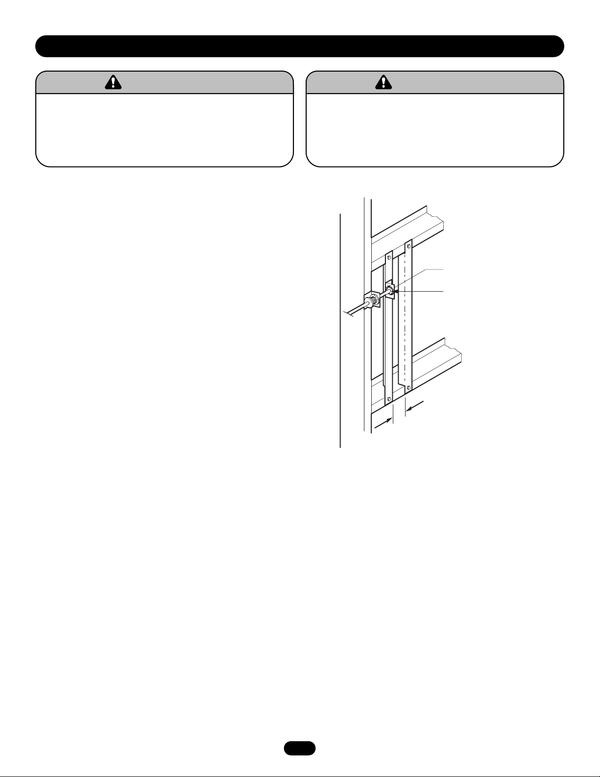
It is imperative that the wall or mounting surface provide adequate
support for the operator.
This surface must:
a. Be rigid to prevent play between operator and door shaft.
b. Provide a level base.
c. Permit the operator to be fastened securely and with the drive
shaft parallel to the door shaft.
The safety and wear of the operator will be adversely affected if
any of the above requirements are not met.
For metal buildings, fasten 2"x 2" x 3/16" (or larger) angle iron
frames to the building purlins. Retain 7" between frames.
7.00"
PREPARATION
To avoid damage to door and operator, make all door locks
inoperative. Secure lock(s) in “OPEN” position.
If the door lock needs to remain functional, install an interlock
switch.
DO NOT connect electric power until instructed to do so.
WARNING
WARNING
Keep door balanced. Sticking or binding doors MUST be
repaired. Doors, door springs, cables, pulleys, brackets and
their hardware may be under extreme tension and can cause
SERIOUS PERSONAL INJURY or DEATH. Call a professional
door serviceman to move or adjust door springs or hardware.
WARNING
WARNING
Shaft Support Bracket
with Bearing (Not Provided)
Door Sprocket
5-1/2"
Page 5
Be sure door sprocket
is properly aligned with
drive sprocket before
securing to the shaft.
5
OPTIMUM DISTANCE
12-15"
Before your operator is installed, be sure the door has been properly aligned and is working smoothly. The operator may be wall
mounted or mounted on a bracket or shelf. If necessary, refer to the preparation on page 3. Refer to the instructions below that suit
your application.
INSTALLATION
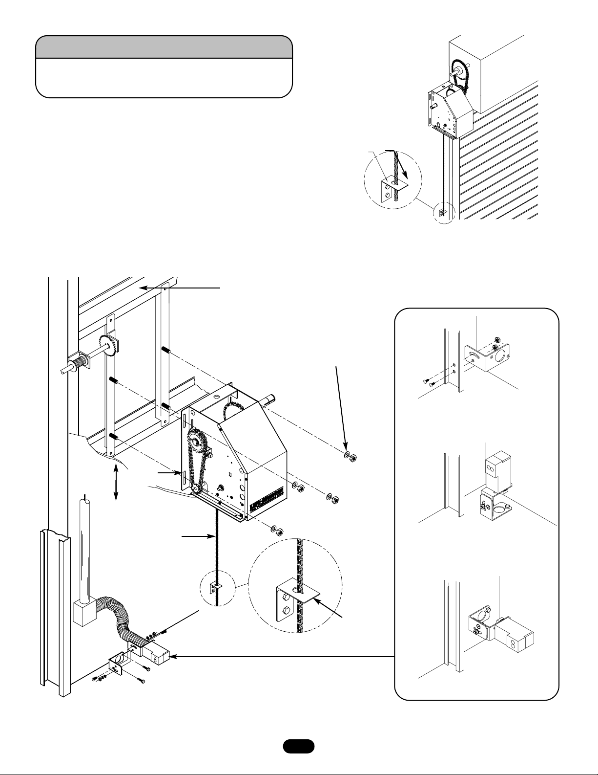
OPERATOR MOUNTING
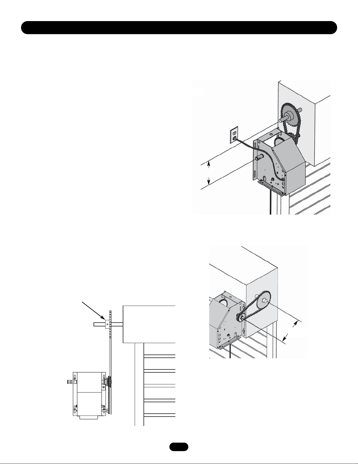
1. Wall Mount: The operator should generally be installed below
the door shaft, and as close to the door as possible (Figure 1).
Bracket or Shelf Mount: The operator may be mounted either
above or below the door shaft (Figure 2).
IMPORTANT: The shelf or bracket must provide adequate support,
prevent play between operator and door shaft, and permit
operator to be fastened securely and with the drive shaft parallel
to the door shaft.
NOTE: The optimum distance between the door shaft and operator
drive shaft is between 12" - 15".
2. Place door sprocket on the door shaft. Do not insert the key
at this time.
3. Place drive sprocket on the appropriate side of the operator.
4. Wrap drive chain around door sprocket and join roller chain
ends together with master link.
5. Raise operator to approximate mounting position and position
chain over operator sprocket.
6. Raise or lower operator until the chain is taut (not tight).
Make sure the operator output shaft is parallel to door shaft
and sprockets are aligned. When in position, secure the
operator to wall or mounting bracket.
7. Insert keys and align sprockets and secure (Figure 3).
Figure 1
Figure 2
Figure 3
OPTIMUM DISTANCE
12-15"
Page 6
6
Keyhole Bracket
MANUAL OPERATION
This operator has a floor level disconnect chain to disconnect the
door from the door operator.
a. To disengage, pull the chain and secure in the disengaged
position by slipping the end through the keyhole bracket
mounted on the wall. If emergency egress device is used, pull
handle to disengage operator from the door.
b. The door may now be pushed up or pulled down manually.
Release the disconnect chain to operate the door again
electrically.
DOOR OPERATING SYSTEM ILLUSTRATION
ALTERNATE MOUNTING
FOR OPTIONAL PHOTO EYES
Rigid Mounting Surface
Keyhole
Bracket
Mounting Hardware
(Not Provided)
Track Mount
Floor Mount
Wall Mount
Pull Chain for
Manual Operation
Turn off power to the operator BEFORE manually operating
your door.
WARNING
CAUTION
WARNING
WARNING
To Adjust
Tension
Page 7

Ground Wire
Ground
Screw
White
Wires
Black
Wires
Figure 3
7
THREE PRONG GROUNDING PLUG
To avoid installation difficulties, do not run the operator at this time.
To reduce the risk of electric shock, this operator has a grounding
type plug with a third grounding pin. This plug will only fit into a
grounding type outlet. If the plug does not fit into the outlet you
have, contact a qualified electrician to install the proper outlet. Do
not change the plug in any way (Figure 1).
PERMANENT WIRING
If permanent wiring is required by your local code, refer to the
following procedure:
To make a permanent connection through the 7/8" diameter hole
in the side of the operator:
1. Remove the cover screws and set the cover aside (Figure 2).
2. Remove the 3-prong cord.
3. Connect the black (hot) wire to the screw on the brass terminal;
the white (neutral) wire to the screw on the silver terminal; and
the ground wire to the green ground screw. The operator must
be grounded (Figure 3).
4. Re-install the cover.
Cover Screws
Figure 1
Figure 2
POWER WIRING & GROUND WIRING
To reduce the risk of SEVERE INJURY or DEATH:
• ANY maintenance to the operator or in the area near the
operator MUST not be performed until disconnecting the
electrical power and locking-out the power via the operator
power switch. Upon completion of maintenance the area MUST
be cleared and secured, at that time the unit may be returned
to service.
• Disconnecting power at the fuse box BEFORE proceeding.
Operator MUST be properly grounded and connected in
accordance with local electrical codes. The operator should be
on a separate fused line of adequate capacity.
• ALL electrical connections MUST be made by a qualified
individual.
• DO NOT install ANY wiring or attempt to run the operator
without consulting the wiring diagram. We recommend that
you install an optional reversing edge before proceeding with
the control station installation.
• ALL power wiring should be on a dedicated circuit and well
protected. The location of the power disconnect should be
visible and clearly labeled.
• ALL power and control wiring MUST be run in separate
conduit.
• BEFORE installing power wiring or control stations be sure to
follow all specifications and warnings described below. Failure
to do so may result in SEVERE INJURY to persons and/or
damage to operator.
WARNING
WARNING
Page 8

8
TWO-BUTTON/TWO POSITION KEY SWITCH
Operator must be programmed to D1 Mode. See programming
instructions, page 9.
1. Locate the door control within sight of the door at a minimum
height of 5 feet where small children cannot reach, and away
from all moving parts of the door and door hardware.
2. Fasten the door control button securely with 6AB X 1-1/2"
screws. If installing into drywall, drill 5/32" holes and use
anchors provided.
3. Run the wire up the wall to the operator. Use insulated staples
to secure the wire in several places. Be careful not to pierce
the wire with a staple.
4. Receiver terminal screws are located inside the operator
access panel on the interface board. Connect each wire to the
corresponding interface board terminals: the “OPEN” terminal
of the wall control connects to “OPEN,” the “CLOSE” terminal
of the wall control connects to “CLOSE,” and the common
terminal of the wall control connects to “CMN” (Figure 2).
THREE BUTTON STATION (STANDARD)
Operator must be programmed to B2 Mode. See programming
instructions, page 9.
1. Locate the door control within sight of the door at a minimum
height of 5 feet where small children cannot reach, and away
from all moving parts of the door and door hardware.
2. Fasten the door control button securely with 6AB X 1-1/2"
screws. If installing into drywall, drill 5/32" holes and use
anchors provided.
3. Run the wire up the wall to the operator. Use insulated staples
to secure the wire in several places. Be careful not to pierce
the wire with a staple.
4. Receiver terminal screws are located inside the operator
access panel on the interface board. Connect each wire to the
corresponding interface board terminals: the “OPEN” terminal
of the wall control connects to “OPEN,” the “CLOSE” terminal
of the wall control connects to “CLOSE,” the “STOP” terminal
connects to “SBC/STOP,” and the common terminal of the wall
control connects to “CMN” (Figure 1).
WARNING
MOUNT WARNING NOTICE
INSTALLATION OF DOOR CONTROLS
Figure 1
Figure 2
WAR N ING
TO PREVENT ENTRAPMENT
DO NOT START DOOR DOWNWARD
UNLESS DOORWAY IS CLEAR
Warning Notice
Page 9

9
PHOTO EYES AND SENSING EDGES
Sensing devices supplied for door industry type operators with an
isolated normally open (N.O.) dry contact output are compatible
with your operator. This includes pneumatic and electric edges,
and through beam and retro reflective photo eyes. If your door
does not have bottom safety photo eyes or a sensing edge and
you wish to add a safety device to your application, please
contact your local LiftMaster Authorized Dealer.
If not pre-installed by the door manufacturer, mount the sensing
edge on the door according to the instructions provided with the
edge. The sensing edge may be electrically connected by either
coiled cord or take-up reel.
IMPORTANT NOTES:
• To install a sensing edge, ask for sensing edge connection kit
LGOSE. This must be installed in order to add a sensing edge.
Refer to instructions on page 10.
• Proceed with Limit Switch Adjustments before making any
sensing edge wiring connections to operator as described
below.
• Electrician must hard-wire the junction box to the operator
electrical box in accordance with local codes.
TAKE-UP REEL: Take-up reel should be installed 12" above the top
of the door.
COIL CORD: Connect operator end of coil cord to junction box
(not provided) fastened to the wall approximately halfway up the
door opening.
TO CHANGE OPERATING MODES
(FACTORY SET TO B2 MODE):
1. Press and hold the LEARN button (The learn LED will light).
NOTE: If the learn/mode button is held for 5 seconds, all learned
transmitters will be erased.
2. To learn the appropriate mode: While holding the LEARN button,
press the corresponding button on the interfaceboard.
B2 Mode: CLOSE Button (S3)
D1 Mode: OPEN Button (S2)
3. Release both buttons. The LEARN LED gives a visual indication of
the mode programmed.
B2 Mode = 2 Blinks
D1 Mode = 1 Blink
PROGRAMMING OPERATING MODES
ENTRAPMENT PROTECTION ACCESSORIES
IMPORTANT NOTE: When optional photo eyes (IR’s) are used,
Wiring Mode B2 must be reprogrammed. IR’s must be connected
and sending a pulse prior to programming. See programming
instructions above.
It is strongly recommended that a safety photo eye or sensing
edge be used in conjunction with the operator.
WARNING
CAUTION
WARNING
WARNING
Page 10

10
CONNECTION PROCEDURE
1. Run the wires from the edge to the operator. Use a take-up
reel or coil cord for this purpose.
2. Refer to local codes for all wiring requirements.
3. Connect one side of the edge to the sensing edge cutout
switch (white wire) using the wire nut supplied.
4. Connect the other side of the sensing edge to the interface
board (IR WH/BK) terminal.
5. Run the door in the close direction, activate edge, and confirm
that the door reverses.
Wire
Nut
Sensing Edge
Switch
S3
Close
S2
Open
Edge
S1
Stop
IR WH/BK
IR WHITE
STOP/SBC
CMN
OPEN
CLOSE
Page 11

11
LIMIT SWITCH ADJUSTMENT
1. To adjust limit nuts, depress retaining plate to allow nut to
spin freely. After adjustment, release plate and ensure it seats
fully in slots of both nuts.
2. To increase door travel, spin nut away from actuator. To
decrease door travel, spin limit nut toward actuator.
3. Adjust open limit nut so that door will stop in open position
with the bottom of the door even with top of door opening.
4. Repeat Steps 1 and 2 for close cycle. Adjust close limit nut so
that actuator is engaged as door fully seats at the floor.
FORCE ADJUSTMENT
The open/down force adjustments are made by adjusting two
control knobs inside the operator end panel. One knob controls
the drive force adjustment. The second knob controls the
sensitivity, which is the change of force as seen by the operator.
To set the forces
1. Adjust the drive force to minimum and the sensitivity to
minimum.
2. Increase the drive force in 10 degree increments until the door
travels freely from limit to limit.
3. Increase the sensitivity in 10 degrees until the door begins to
reverse/stop in mid-travel.
4. Decrease the sensitivity by 10 degrees and run the door
through a complete cycle to confirm normal operation.
If the door stops normal travel of open/close to the limits,
decrease the dive and sensitivity knobs to minimum and repeat
steps 2 through 4.
DRIVE FORCE SENSITIVITY
NOTE: Make sure the limit nuts are positioned between the
limit switch actuators before proceeding with adjustments.
ADJUSTMENTS
To avoid SERIOUS PERSONAL INJURY or DEATH from
electrocution, disconnect electric power BEFORE manually
moving limit nuts.
WARNING
WARNING
Page 12

12
IR BK\WH
IR WHITE
STOP/SBC
CMN
OPEN
CLOSE
CLOSE
OPEN STOP
GY
GY BRYE
MOTOR
CAPACITOR
BL
RD
WH
1
2
3
BK
WH
RD
IN
POWER
9
8
7
6
5
4
3
2
1
RPM
OPEN CLOSE
YE
YE
GY/WH
BR
PU
WH
BK
BL
RD
YE
PU
GY/WH
GY
GROUND
DEVICE
SENSING
GN
BK
WH
OPEN
CLOSE
CONTROL WIRING
POWER WIRING
THREE
BUTTON
WALL CONTROL
GN
BK
WH
STOP
WIRING DIAGRAM
Page 13

13
TESTING THE OPERATOR
Turn on power. Test all controls and safety devices to make sure
they are working properly. It will be necessary to refer to page 11
for fine adjustment of the limit switches.
IMPORTANT NOTES:
• Do not leave operator power on unless all safety and
entrapment protection devices have been tested and are
working properly.
•. Be sure you have read and understand all Safety Instructions
included in this manual.
• Be sure the owner or person(s) responsible for operation of the
door have read and understand the Safety Instructions, know
how to electrically operate the door in a safe manner, and know
how to use the manual disconnect operation of the door
operating system.
TROUBLESHOOTING GUIDE
SITUATION PROBABLE CAUSE & SOLUTION
The door operates from the door control, but not from
the remote control.
The door doesn’t open completely.
The door opens but won’t close.
The door reverses for no apparent reason.
The operator does not operate from either the door
control or the remote control.
Are you in the correct operating mode?
Is the remote programmed?
If the door has been working properly but now doesn’t open
all the way, readjust the force setting.
Check the safety reversal system; check the sensitivity.
Remove any obstruction and check the safety reversing
system. In two-button mode, check for shorted wires to the
reversing edge. Check drive force and sensitivity adjustments.
Are you in the proper operating mode for the wall control?
Is the wall control properly wired to the interface board?
TROUBLESHOOTING
Do NOT place hands or tools in or near the operator when the
power is on or when testing control or safety devices. To avoid
SERIOUS PERSONAL INJURY or DEATH from electrocution,
ALWAYS disconnect electric power BEFORE servicing or
adjusting the operator.
WARNING
WARNING
Page 14

14
Use SAE 30 Oil (Never use grease or silicone spray).
Repeat ALL procedures.
Do not lubricate motor. Motor bearings are rated for
continuous operation.
Inspect and service whenever a malfunction is observed or
suspected.
CAUTION: BEFORE SERVICING, ALWAYS DISCONNECT
OPERATOR FROM POWER SUPPLY.
Check at the intervals listed in the following chart.
ATTENTION ELECTRICIAN
Use 16 gauge or heavier for all control wiring.
OPEN
CLOSE
CMN
SBC/STOP
CLOSE
OPEN
CMN
IR BK\WH
IR WHITE
SENSING DEVICES
THREE BUTTON STATION TWO BUTTON STATION
MAINTENANCE SCHEDULE
CONTROL CONNECTIONS
EVERY EVERY EVERY
ITEM PROCEDURE 3 MONTHS 6 MONTHS 12 MONTHS
Drive Chain Check for excessive slack.
Check and adjust as required.
Lubricate.
Sprockets Check set screw tightness.
Fasteners Check and tighten, as required.
Manual Disconnect Check and operate.
Bearings and Shafts Check for wear and lubricate.
Page 15

15
5
L11
L13
L10
L15
L16
E7
7
E2
E1
E8
E14
L9
L12
11
L14
L18
L17
4
10
E12
S2
S3
R10
S1
M1
M2
E11
E4
E17
2
E15
E9
E10
E3
E13
E6
M3
9
8
4
3
E16
9
8
D6
D2
D7
D12
D11
L4
L3
1
D13
D1
D5
D13
R1
R5
R4
R3
R9
L8
L1
L6
L7
R2
L20
R3
R5
R7
R6
L6
L5
L7
L2
O6
O2
O6
O4
O5
O3
D4
D8
O4
D10
D9
O5
O3
O1
R8
D9
D14
D3
ILLUSTRATED PARTS
Page 16

16
MODEL LGO REPAIR PARTS KITS
Refer to the parts lists below for replacement kits available for your operator. If optional modifications and/or accessories are included
with your operator, certain components may be added or removed from these lists. Individual components of each kit may not be
available. Please consult a parts and service representative regarding availability of individual components.
K75-16424 MOTOR KIT
ITEM PART # DESCRIPTION QTY
M1 --- Motor 1
M2 --- Bracket 1
M3 11A34 Bearing, Oil Impregnated 1
K72-16422 OUTPUT SHAFT KIT
ITEM PART # DESCRIPTION QTY
O1 11-15646 Output Shaft, 1" 1
O2 15-48B32LXX Sprocket, 1" I.D., 32 Tooth 1
O3 12-10715 Bushing, 1" I.D., Keyed 2
O4 80-206-10 Shim Washer, 1" I.D., .015 Thk 6
O5 87-E-100 E-Ring, 1" 2
O6 86-RP10-200 Roll Pin, 5/16" X 2" Long 1
ELECTRONICS
ITEM PART # DESCRIPTION QTY
E1 K001A5251-4 Logic Board 1
E2 82-WX08-06T Screw, #8-32 X 3/8" Long 2
E3 29-10339 Capacitor 1
E4 10-10351 Capacitor Bracket 1
E5 171A384 Screw, #8-32 1
E6 1B3878 Terminal Block, 120 Volt 1
E7 --- Shield, PCB Panel 1
E8 --- Standoff 2
E9 K79-15491 PCB, 3 Button Interface 1
E10 216A149 Washer, Term. Cup #8, Ground 1
E11 --- Ground Screw 1
E12 41B4245 Power Cord, 4 Foot 1
E13 --- Strain Relief, Power Cord 1
E14 10-15641 Bracket, 120 Volt Terminal Block 1
E15 10-15640 Bracket, PCB Interface 1
E16 75-13705 Standoff Assy. PCB Interface 4
E17 171A0384 Screw, #8-32 3
K72-16423 DISCONNECT SHAFT KIT
ITEM PART # DESCRIPTION QTY
D1 10-11394 Release Lever 1
D2 11-15648 Disconnect Shaft 1
D3 75-11377 Sprocket 1
D4 07-11419 Disconnect Hub 1
D5 19-8A-12 Sash Chain, 12' 1
D6 --- Support Bracket 1
D7 10-11023 Bevel Gear Yoke 1
D8 18-10467 Spring, Compression 1
D9 87-E-100 E-Ring, 1", Plated 2
D10 80-11416 Key, Disconnect, 1/4 X 1/4 X 7/8" 2
D11 82-SH10-12 Screw, #10-32, H.H. Socket 2
D12 85-LS-10 Lock Washer, #10, ZP 2
D13 86-CP04-112 Cotter Pin, 1/8 X 1-3/4" Long 4
D14 86-RP04-100 Roll Pin, 1/8" dia X 1" 2
D15 80-206-11 Washer, 1" I.D. X 1-1/16" Thk 1
INDIVIDUAL COMPONENTS
K72-16421 LIMIT SHAFT KIT
K72-16425 REDUCTION SHAFT KIT
K75-16426 RPM SENSOR KIT
K74-16420 LIMIT SWITCH KIT
ITEM PART # DESCRIPTION QTY
S1 --- RPM Board 1
S2 --- Bracket 1
S3 --- Interrupter Cup 1
ITEM PART # DESCRIPTION QTY
R1 --- Shaft, Reduction, 1/2" 1
R2 81B45 Drive Gear, 1/2" I.D. 1
R3 146A53 Roll Pin, .187 X 15/16" Long 2
R4 15-48B12CXX Sprocket, 1/2" I.D., 12 Tooth 1
R5 --- Bushing, 1/2" I.D., Keyed 2
R6 216A148 Shim Washer, 1/2" I.D., .030 Thk 4
R7 158A30 E-Ring, 1/2" 2
R8 22A3 Chain, #48, 54 Pitch 1
R9 146A53 Roll Pin, 3/16" X 15/16" Long 1
R10 81C179 Worm Gear 1
ITEM PART # DESCRIPTION QTY
L9 --- Screw, #10-32 x 1/2" 4
L10 --- Depress Plate 1
L11 146A53 Roll Pin, .187 X 15/16" Long 2
L12 82-PX06-16 Screw #6-32 x 1" 2
L13 84-LH-06 Nut #6-32 2
L14 31-12542 Standoff 2
L15 82-PX04-20 Screw #4-40 4
L16 10-12806 Nut Plate, Through 2
L17 10-12553 Nut Plate, Threaded 2
L18 23-10041 Limit Switch 2
ITEM PART # DESCRIPTION QTY
L1 --- Limit Shaft 3/8" 1
L2 13-10024 Limit Nut 2
L3 15-48B9A1 Sprocket, 9 Tooth 1
L4 86-RP04-100 Roll Pin, 1/8" dia X 1" 1
L5 12-10028 Bushing, 3/8" I.D., Keyed 2
L6 87-E-038 E-Ring, 3/8" 2
L7 80-10025 Shim Washer, 3/8"dia. X .050 Thk 2
L8 80-10026 Shim Washer 3/8"dia. X .010 Thk 6
ITEM PART # DESCRIPTION QTY
1 10-15643 Frame 2
2 --- Frame, Spacer 3
3 --- Bracket,Panel Shield Mtg. 1
4 --- Screw, #8-32 X 3/8" long 14
5 --- Rivet 3
6 --- Screw, Captive Mounting 2
7 --- Hinge 1
8 --- Bolt,Carriage Head, 5/16-18 X 1" 6
9 --- Nut, Serrated Flange, 5/16-18 6
10 10-15644 Cover 1
11 10-15642 Limit Frame 1
Page 17

LIFTMASTER®TWO YEAR LIMITED WARRANTY
The Chamberlain Group, Inc. warrants to the first retail purchaser of this product, for the structure in which this product is originally
installed, that it is free from defect in materials and/or workmanship for a period of two years from the date of purchase. The proper
operation of this product is dependent on your compliance with the instructions regarding installation, operation, maintenance and
testing. Failure to comply strictly with those instructions will void this limited warranty in its entirety.
If, during the limited warranty period, this product appears to contain a defect covered by this limited warranty, call 1-800-528-2806,
toll free, before dismantling this product. Then send this product, pre-paid and insured, to our service center for warranty repair. You
will be advised of shipping instructions when you call. Please include a brief description of the problem and a dated proof-of-purchase
receipt with any product returned for warranty repair. Products returned to Seller for warranty repair, which upon receipt by Seller are
confirmed to be defective and covered by this limited warranty, will be repaired or replaced (at Seller’s sole option) at no cost to you
and returned pre-paid. Defective parts will be repaired or replaced with new or factory-rebuilt parts at Seller’s sole option.
ALL IMPLIED WARRANTIES FOR THE PRODUCT, INCLUDING BUT NOT LIMITED TO ANY IMPLIED WARRANTIES OF
MERCHANTABILITY AND FITNESS FOR A PARTICULAR PURPOSE, ARE LIMITED IN DURATION TO THE TWO YEAR LIMITED
WARRANTY PERIOD SET FORTH ABOVE, AND NO IMPLIED WARRANTIES WILL EXIST OR APPLY AFTER SUCH PERIOD. Some states
do not allow limitations on how long an implied warranty lasts, so the above limitation may not apply to you. THIS LIMITED
WARRANTY DOES NOT COVER NON-DEFECT DAMAGE, DAMAGE CAUSED BY IMPROPER INSTALLATION, OPERATION OR CARE
(INCLUDING, BUT NOT LIMITED TO ABUSE, MISUSE, FAILURE TO PROVIDE REASONABLE AND NECESSARY MAINTENANCE,
UNAUTHORIZED REPAIRS OR ANY ALTERATIONS TO THIS PRODUCT), LABOR CHARGES FOR REINSTALLING A REPAIRED OR
REPLACED UNIT, OR REPLACEMENT OF BATTERIES.
THIS LIMITED WARRANTY DOES NOT COVER ANY PROBLEMS WITH, OR RELATING TO, THE GARAGE DOOR OR GARAGE DOOR
HARDWARE, INCLUDING BUT NOT LIMITED TO THE DOOR SPRINGS, DOOR ROLLERS, DOOR ALIGNMENT OR HINGES. THIS
LIMITED WARRANTY ALSO DOES NOT COVER ANY PROBLEMS CAUSED BY INTERFERENCE. ANY SERVICE CALL THAT
DETERMINES THE PROBLEM HAS BEEN CAUSED BY ANY OF THESE ITEMS COULD RESULT IN A FEE TO YOU.
UNDER NO CIRCUMSTANCES SHALL SELLER BE LIABLE FOR CONSEQUENTIAL, INCIDENTAL OR SPECIAL DAMAGES ARISING IN
CONNECTION WITH USE, OR INABILITY TO USE, THIS PRODUCT. IN NO EVENT SHALL SELLER’S LIABILITY FOR BREACH OF
WARRANTY, BREACH OF CONTRACT, NEGLIGENCE OR STRICT LIABILITY EXCEED THE COST OF THE PRODUCT COVERED HEREBY.
NO PERSON IS AUTHORIZED TO ASSUME FOR US ANY OTHER LIABILITY IN CONNECTION WITH THE SALE OF THIS PRODUCT.
Some states do not allow the exclusion or limitation of consequential, incidental or special damages, so the above limitation or
exclusion may not apply to you. This limited warranty gives you specific legal rights, and you may also have other rights which vary
from state to state.
WARRANTY POLICY
17
Page 18

18
OPERATOR NOTES
Page 19

19
OPERATOR NOTES
Page 20

© 2005, The Chamberlain Group, Inc.
01-32369B All Rights Reserved Printed in Mexico
HOW TO ORDER REPAIR PARTS
OUR LARGE SERVICE ORGANIZATION
SPANS AMERICA
INSTALLATION AND SERVICE INFORMATION
ARE AVAILABLE 6 DAYS A WEEK
CALL OUR TOLL FREE NUMBER
1-800-528-2806
HOURS 6:00 a.m. TO 7:00 p.m. (Central Std. Time)
MONDAY Through FRIDAY
HOURS 8:00 a.m. TO 6:00 p.m. (Central Std. Time)
SATURDAY
www.liftmaster.com
WHEN ORDERING REPAIR PARTS
PLEASE SUPPLY THE FOLLOWING INFORMATION:
PART NUMBER DESCRIPTION MODEL NUMBER
ADDRESS ORDER TO:
THE CHAMBERLAIN GROUP, INC.
Electronic Parts & Service Dept.
6020 S. Country Club Road
Tucson, AZ 85706
REPAIR PARTS & SERVICE
 Loading...