

Page 1
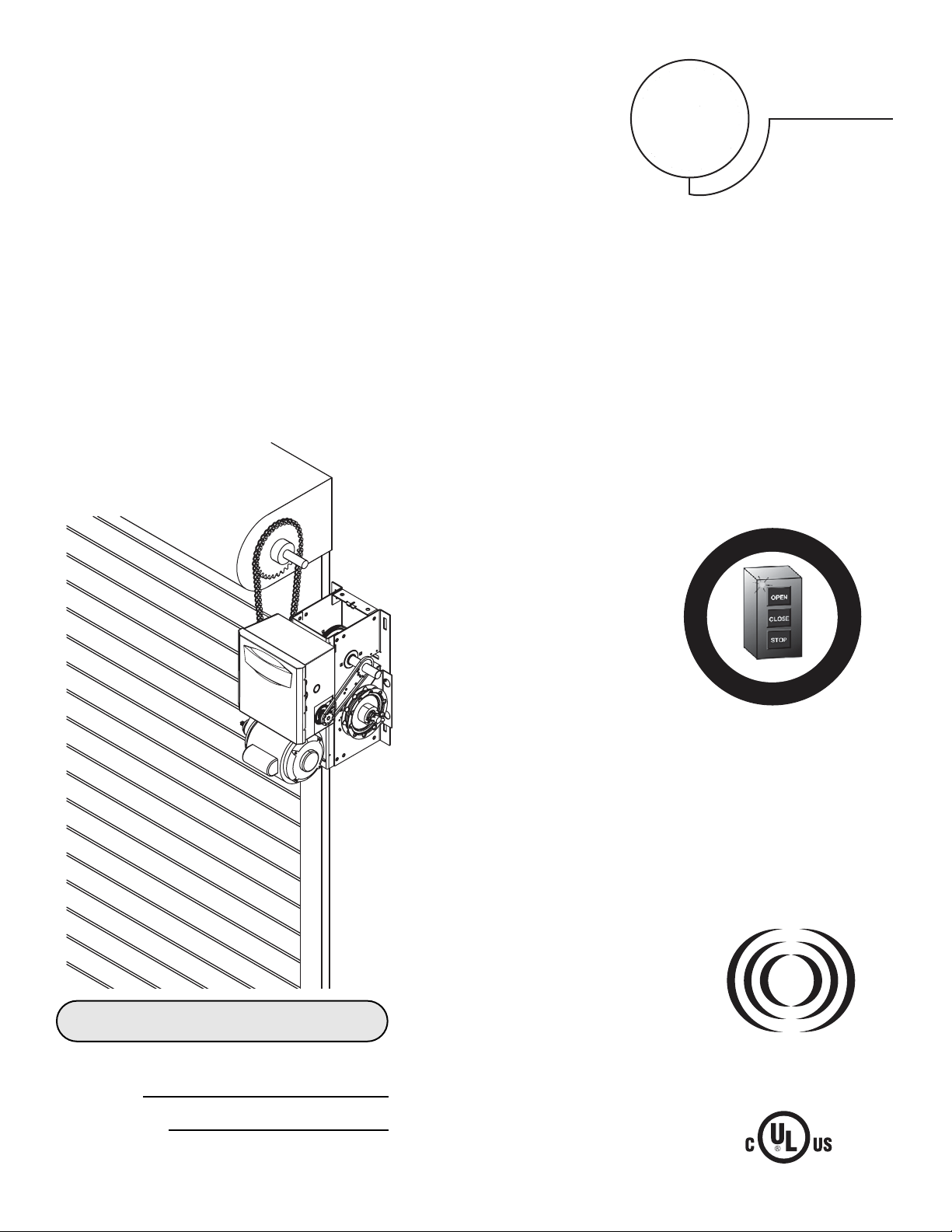
OO WW NN EE RR ’’ SS MM AA NN UU AA LL
JJ HH HH JJ
IINNDDUUSSTTRRIIAALL DDUUTTYY CCOOMMMMEERRCCIIAALL DDOOOORR OOPPEERRAATTOORR
ogic
L
3
NOT FOR RESIDENTIAL USE
A
L
E
R
T
S
Y
S
T
E
M
M
A
I
N
T
E
N
A
N
C
E
PATENT PENDING
The Maintenance Alert System™ allows the
installer to set an internal Maintenance
Cycle Counter. The Logic 3 operator
incorporates a self-diagnostic feature built
into the (MAS) Maintenance Alert System
LED. An LED on the 3-button station will
signal when the set number of
cycles/months is reached or when the
operator requires immediate service.
This Operator Features
the Enhanced
Radio Receiver
Built on Board
Serial # Box
Installation Date
2 YEAR WARRANTY
315MHz
Page 2
When you see these Safety Symbols and Signal Words on the
following pages, they will alert you to the possibility of serious
injury or death if you do not comply with the warnings that
accompany them. The hazard may come from something
mechanical or from electric shock. Read the warnings carefully.
When you see this Signal Word on the following pages, it will
alert you to the possibility of damage to your door and/or the
door operator if you do not comply with the cautionary
statements that accompany it. Read them carefully.
Mechanical
Electrical
TABLE OF CONTENTS
WARNING
WARNING
WARNING
WARNING
CAUTION
WARNING
WARNING
2
SPECIFICATIONS
Carton Inventory . . . . . . . . . . . . . . . . . . . . . . . . . . . . . . . . . . . . .3
Operator Dimensions . . . . . . . . . . . . . . . . . . . . . . . . . . . . . . . . .3
Operator Specifications . . . . . . . . . . . . . . . . . . . . . . . . . . . . . . . .4
PREPARATION
Hand Chain Handing . . . . . . . . . . . . . . . . . . . . . . . . . . . . . . . . . .5
INSTALLATION
Mount the Operator . . . . . . . . . . . . . . . . . . . . . . . . . . . . . . . . . . .6
Manual Operation . . . . . . . . . . . . . . . . . . . . . . . . . . . . . . . . . . . .7
Entrapment Protection Accessories . . . . . . . . . . . . . . . . . . . . . .8
ADJUSTMENT
Limit Switch Adjustment . . . . . . . . . . . . . . . . . . . . . . . . . . . . . . .8
Brake Adjustment . . . . . . . . . . . . . . . . . . . . . . . . . . . . . . . . . . . .9
Clutch Adjustment and Auxiliary Reversal System . . . . . . . . . . .9
POWER & GROUND WIRING
Safety Warnings . . . . . . . . . . . . . . . . . . . . . . . . . . . . . . . . . . . .10
Power Wiring Connections . . . . . . . . . . . . . . . . . . . . . . . . . . . .10
Ground Wiring Connections . . . . . . . . . . . . . . . . . . . . . . . . . . .10
CONTROL STATION WIRING & INSTALLATION
Control Wiring Connections . . . . . . . . . . . . . . . . . . . . . . . . . . .11
Mounting Instructions . . . . . . . . . . . . . . . . . . . . . . . . . . . . . . . .11
External Radio Wiring Connections . . . . . . . . . . . . . . . . . . . . . .11
DIAGRAMS
Standard Power & Control Connection Diagrams . . . . . . . . . . .12
1 Phase Wiring Diagram . . . . . . . . . . . . . . . . . . . . . . . . . . . . . .13
3 Phase Wiring Diagram . . . . . . . . . . . . . . . . . . . . . . . . . . . . . .14
Logic Board . . . . . . . . . . . . . . . . . . . . . . . . . . . . . . . . . . . . . . . .15
PROGRAMMING
Logic Control Pushbuttons . . . . . . . . . . . . . . . . . . . . . . . . . . . .16
Determine and Set Wiring Type . . . . . . . . . . . . . . . . . . . . . . . .16
Failsafe Wiring Types . . . . . . . . . . . . . . . . . . . . . . . . . . . . . . . .17
Self-Monitoring Safety Device Options . . . . . . . . . . . . . . . . . . .17
Programming Remotes . . . . . . . . . . . . . . . . . . . . . . . . . . . .18-19
Maintenance Alert System (MAS) . . . . . . . . . . . . . . . . . . . . . . .20
Mid Stop . . . . . . . . . . . . . . . . . . . . . . . . . . . . . . . . . . . . . . . . . .21
Timer to Close . . . . . . . . . . . . . . . . . . . . . . . . . . . . . . . . . . .21-22
AUTOMATICALLY LEARNED PROGRAMMING
Auxiliary Reversal System/RPM Sensor. . . . . . . . . . . . . . . . . . . 22
Maximum Run Timer (MRT) . . . . . . . . . . . . . . . . . . . . . . . . . . . 23
OPTIONAL PROGRAMMING
Red/Green Warning Light Card . . . . . . . . . . . . . . . . . . . . . . . . . 23
Resetting Factory Defaults - Clearing Memory. . . . . . . . . . . . . . 24
MAINTENANCE SCHEDULE
. . . . . . . . . . . . . . . . . . . . . . . . 24
TROUBLESHOOTING
Diagnostic Chart. . . . . . . . . . . . . . . . . . . . . . . . . . . . . . . . . . . . . 25
Troubleshooting Guide . . . . . . . . . . . . . . . . . . . . . . . . . . . . . . . . 26
Troubleshooting Error Codes . . . . . . . . . . . . . . . . . . . . . . . . . . . 27
Troubleshooting Radio Functionality . . . . . . . . . . . . . . . . . . . . . 28
REPAIR PARTS
Electrical Box . . . . . . . . . . . . . . . . . . . . . . . . . . . . . . . . . . . . 30-31
Repair Parts Kits - Model J. . . . . . . . . . . . . . . . . . . . . . . . . . 32-33
Repair Parts Kits - Model H . . . . . . . . . . . . . . . . . . . . . . . . . 34-35
Repair Parts Kits - Model HJ . . . . . . . . . . . . . . . . . . . . . . . . 36-37
Operator Notes . . . . . . . . . . . . . . . . . . . . . . . . . . . . . . . . . . . 38-39
Control Connection Diagram . . . . . . . . . . . . . . . . . . . . . . . . . . . 40
IMPORTANT NOTES:
• BEFORE attempting to install, operate or maintain the operator,
you must read and fully understand this manual and follow all
safety instructions.
• DO NOT attempt repair or service of your commercial door and
gate operator unless you are an Authorized Service Technician.
Page 3
Before beginning your installation check that all components were provided.
CARTON INVENTORY
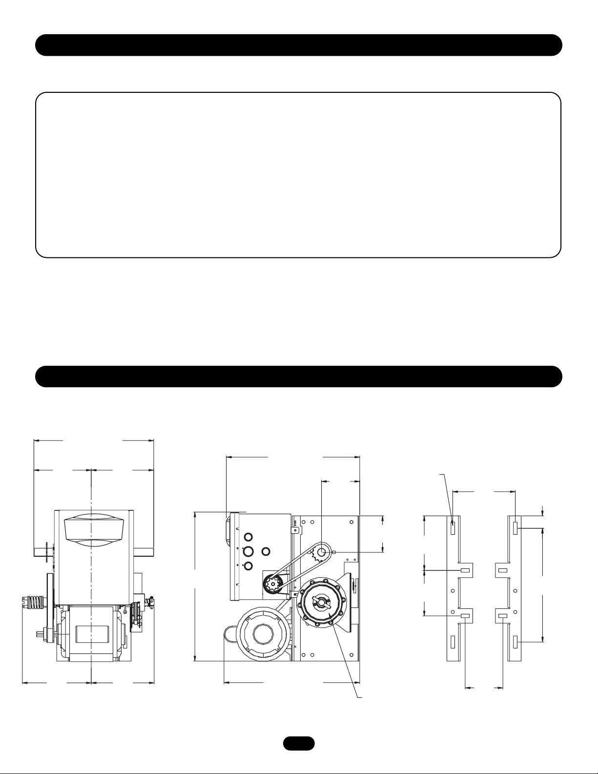
OPERATOR DIMENSIONS
3
MOUNTING DIMENSIONS
A - Wall Mounting
B - Bracket Mounting (rolling door)
WEIGHTS AND DIMENSIONS
HANGING WEIGHT: 80-110 LBS. (36.3-49.9 kg)
DESCRIPTION
POWERHEAD ASSEMBLY
OWNER’S MANUAL AND CAUTION LABELS
HARDWARE BOX (INCLUDES FASTENERS, DISCONNECT AND CHAIN HOIST WALL BRACKET)
3-BUTTON CONTROL STATION WITH LED
HOIST HAND CHAIN (MODELS H & HJ ONLY)
DOOR SPROCKET
DOOR/OPERATOR DRIVE CHAIN
14.50" (63.83 cm)
6.94"
(17.63 cm)
7.56"
(19.2 cm)
20.15"
(51.18 cm)
16.81" (42.7 cm)
4.62"
(11.7 cm)
4.41"
(11.2 cm)
3/8" Bolt
7.56"
(19.2 cm)
1.50" (3.81 cm)
6.59"
(16.7 cm)
5.50"
(14.0 cm)
A
B
B
A
A
B
B
A
13.75"
(34.93 cm)
8.34"
(21.18 cm)
7.62"
(19.35 cm)
16.43" (41.73 cm)
Hand Chain Wheel
Present with Models
H and HJ Only.
4.56"
(11.58 cm)
Page 4

4
OPERATOR SPECIFICATIONS
SAFETY
DISCONNECT:
Model J . . .Floor level disconnect for manual door operation.
Model H . . . . . . . . . . . . .Floor level chain hoist with electrical
interlock for manual door operation.
Model HJ . . . . . . . . . . . .Includes both floor level disconnect
systems stated above.
SAFETY PHOTO EYES (Optional CPS-L): . . .Through beam or retro
reflective
devices used to provide non-contact safety protection.
SAFETY EDGE (Optional): Electric or pneumatic sensing device
attached to the bottom edge of door.
MOTOR
TYPE:. . . . . . . . . . . . . . . . . . . . . . . . . . . . . . . . Continuous Duty
HORSEPOWER: . . . . . . . . . . . . . . . . . . . 1/3, 1/2, 3/4 and 1 HP
SPEED: . . . . . . . . . . . . . . . . . . . . . . . . . . . . . . . . . . . 1725 RPM
VOLTAGE:. . . . . . . . . . . . . . . . . . . . . . . . . . . 115/230V 1 Phase,
208/230/380/460/575V 3 Phase
CURRENT: . . . . . . . . . . . . . . . . . . . . . . . . See Motor Nameplate
ELECTRICAL
TRANSFORMER: . . . . . . . . . . . . . . . . . . . . . . .24Vac Secondary
CONTROL STATION: . . . . . . . . . . . . . . .NEMA 3-Button Station
Open/Close/Stop w/LED
WIRING TYPE: . . . . . . . . . . . . . . . . . . . . . . . . . . .C2 (Standard)
Momentary contact to OPEN & STOP, constant pressure to
CLOSE, plus wiring for sensing device to reverse and auxiliary
devices to open and close with open override. See pages 16 and
17 for optional wiring types and operating modes.
LIMIT ADJUST: . . . . .Linear driven, fully adjustable screw type
cams.
MECHANICAL
DRIVE REDUCTION: . . . . . . . .Primary: Heavy duty (5L) V-Belt
Secondary: #48 chain/sprocket; Output: #50 chain
OUTPUT SHAFT SPEED: . . . . . . . . . . . . . . . . . . . . . . . .36 RPM
DOOR SPEED: . . . . . . . . . . .6-7" (15.24-17.78 cm) per second
depending on door
BRAKE (Optional): . . . . . . . . . . . .Solenoid actuated disc brake
BEARINGS: . . . . . . . . . . . . .Output Shaft Shielded ball bearing;
Clutch Shaft: Iron Copper sintered and oil impregnated
HAND CHAIN WHEEL: . . . . . . . . . . . . . . . .Left or right handing
Models H and HJ ONLY
Page 5
5
PREPARATION
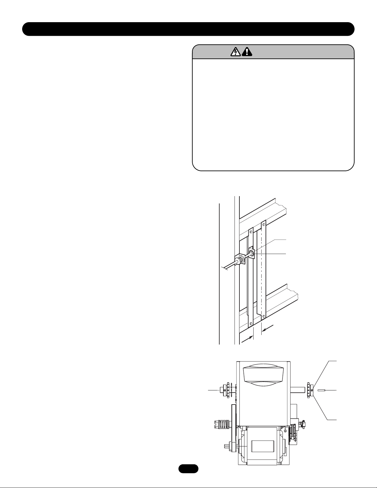
It is imperative that the wall or mounting surface provide
adequate support for the operator.
This surface must:
a. Be rigid to prevent play between operator and door shaft.
b. Provide a level base.
c. Permit the operator to be fastened securely and with the
drive shaft parallel to the door shaft.
The safety and wear of the operator will be adversely affected if
any of the above requirements are not met. For metal buildings,
fasten 2" x 2" x 3/16" (or larger) angle iron frames to the building
purlins. Retain 5-1/2" (13.97 cm) between frames.
Both J and H series operators have dual output shafts and may
be mounted on either the right (standard) or left side of door, and
in either a vertical (standard) or horizontal mounting position. If
you need to move the drive sprocket, loosen BOTH set screws,
remove the sprocket and key, and place on the opposite side of
the drive shaft. Be sure to tighten BOTH set screws securely.
HAND CHAIN HANDING
For models H and HJ with manual hoist hand chain systems, the
handing of the operator must be determined at the time of order.
The handing is indicated by last letter of the model name
(R or L). The hand chain wheel can not be switched on site. If
your installation causes the hand chain to hang in the door
opening, hook the chain off to the side near the top of the door
jamb.
To prevent possible SERIOUS INJURY or DEATH:
• DO NOT connect electric power until instructed to do so.
• If the door lock needs to remain functional, install an
interlock switch.
• ALWAYS call a trained professional door serviceman if door
binds, sticks or is out of balance. An unbalanced door may
not reverse when required.
• NEVER try to loosen, move or adjust doors, door springs,
cables, pulleys, brackets or their hardware, ALL of which are
under EXTREME tension and can cause SERIOUS PERSONAL
INJURY.
• Disable ALL locks and remove ALL ropes connected to door
BEFORE installing and operating door operator to avoid
entanglement.
WARNING
WARNING
Shaft Support Bracket
with Bearing (Not Provided)
Door Sprocket
5-1/2" (13.97 cm)
(2) Set
Screws
Output
Shaft
Key
Drive
Sprocket
Page 6
6
INSTALLATION
IMPORTANT NOTE: Before your operator is installed, be sure the door has been properly aligned and is working smoothly. The
operator may be wall mounted or mounted on a bracket or shelf. If necessary, refer to the preparation on page 5. Refer to the
illustrations and instructions below that suit your application.
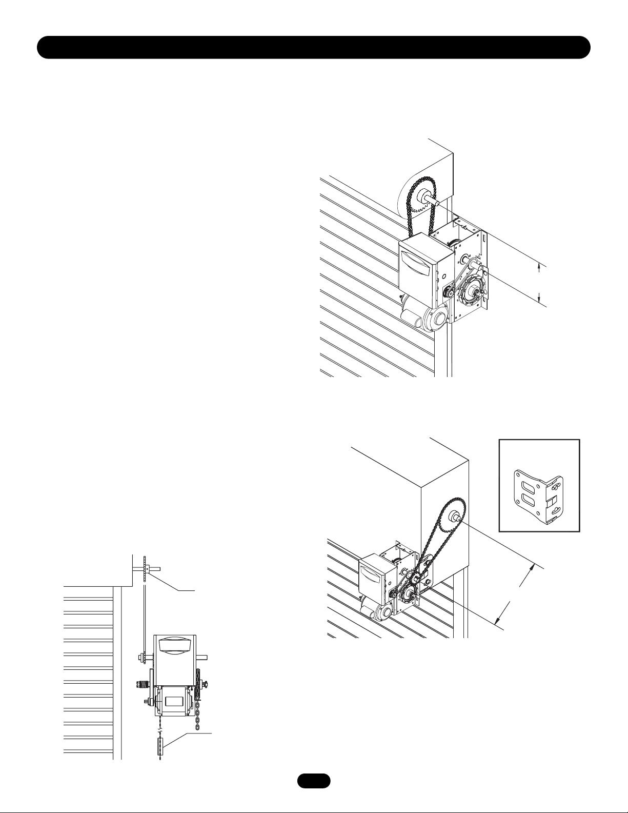
MOUNT THE OPERATOR
1. Wall Mount: The operator should generally be installed below
the door shaft, and as close to the door as possible (Figure 1).
Bracket Shelf Mounting: The operator may be mounted either
above or below the door shaft (Figure 2).
IMPORTANT: The shelf or bracket must provide adequate support,
prevent play between operator and door shaft, and permit
operator to be fastened securely and with the drive shaft parallel
to the door shaft.
NOTE: The optimum distance between the door shaft and
operator drive shaft is between 12-15" (30.5-38.1 cm).
2. Place door sprocket on the door shaft. Do not insert the key
at this time.
3. Place drive sprocket on the appropriate side of the operator.
Do not insert the key at this time.
4. Wrap drive chain around door sprocket and join roller chain
ends together with master link.
5. Raise operator to approximate mounting position and position
chain over operator sprocket.
6. Raise or lower operator until the chain is taut (not tight).
Make sure the operator output shaft is parallel to door shaft
and sprockets are aligned. When in position, secure the
operator to wall or mounting bracket.
7. Align sprockets and secure (Figure 3).
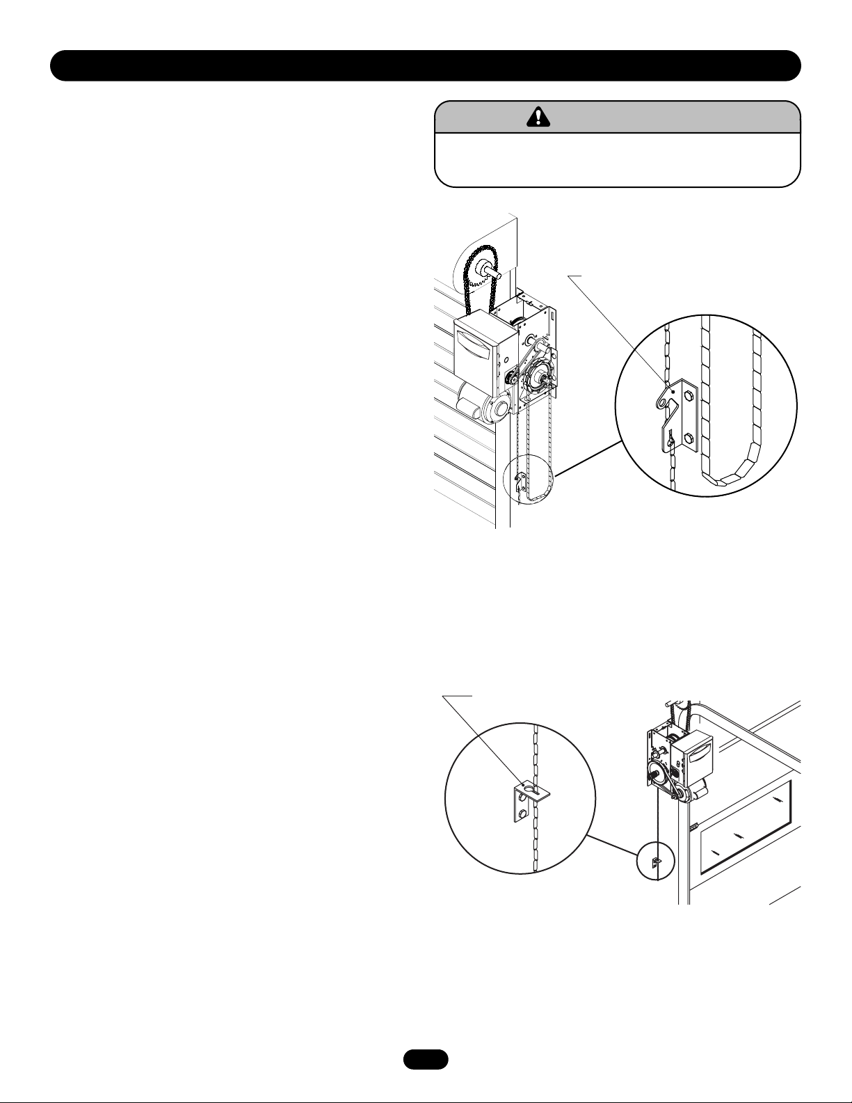
8. Install Hand Chain (Models H and HJ only)
Place hand chain around hand chain wheel. Be sure to pass it
through both openings in the chain guide. Remove enough
links so chain hangs approximately 2' (.61 m) above the floor.
9. Mount Chain Keeper / Keyhole Bracket
Using suitable hardware mount the chain keeper
approximately 4' (1.22 m) above the floor, near the free
hanging chain. Remove disconnect sash chain from bag and
place the end through the keyhole in the the chain keeper.
Remove excess links if necessary.
Optimum Distance
12-15" (30.5-38.1 cm)
Typical Right Hand
Wall Mounted Operator
Optimum Distance
12-15" (30.5-38.1 cm)
OPTIONAL
Mounting Bracket
P/N 08-9098
Be sure door
sprocket is properly
aligned with drive
before securing to
the shaft.
Chain Keeper
4' (1.22 m) above floor
Figure 1
Figure 2
Figure 3
Page 7
7
MANUAL OPERATION
This operator has provisions for manually operating the door in
case of emergency or power failure.
To prevent possible SERIOUS INJURY from a moving chain,
ENGAGE interlock BEFORE manually operating your door.
WARNING
WARNING
MODEL H
These operators are equipped with a manual hoist. An electrical
interlock will disable the electrical controls when the hoist is used.
To operate the hoist:
1. Pull the disconnect chain (small chain) to engage the interlock
to disable the controls. The disconnect chain may be locked in
position by slipping the end through the keyhole of the chain
keeper mounted on the wall.
2. Operate the door in the desired direction by pulling on one side
or the other of the continuous loop hoist chain (large chain).
3. The disconnect chain must be released from the chain keeper
before the door will operate again electrically.
MODEL J
This operator has a floor level disconnect chain to disconnect the
door from the door operator.
1. To disengage, pull the chain and secure in the disengaged
position by slipping the end through the keyhole bracket
mounted on the wall. Or if emergency egress device is used,
pull handle to disengage operator from door.
2. The door may now be pushed up or pulled down manually.
Release the disconnect chain to operate the door again
electrically.
MODEL HJ
This operator includes both a floor level disconnect chain to
disconnect the door from the door operator and a disconnect
chain with manual hoist to electrically disable the operator
controls.
1. Refer to Model H instructions for hoist operation.
2. Refer to Model J instructions for manual operation.
Chain Keeper
(with pad locking provisions)
Electrical Interlock with Hoist for Models H and HJ
INSTALLATION
Keyhole Bracket
Manual Disconnect for Models J and HJ
Page 8
8
ENTRAPMENT PROTECTION ACCESSORIES
(OPTIONAL)
PHOTO EYES & SENSING EDGES
Sensing devices provided for door industry type operators with an
isolated normally open (N.O.) dry contact output are compatible
with your operator. This includes pneumatic and electric edges,
and through beam and retro reflective photo eyes. If you would
like to order or receive more information on safety devices, please
contact your local Authorized Dealer.
If not pre-installed by the door manufacturer, mount the sensing
edge on the door according to the instructions provided with the
edge. The sensing edge may be electrically connected by either
coiled cord or take-up reel.
Important Notes:
a. Proceed with Limit Switch Adjustments described below before
making any sensing edge wiring connections to operator.
b. Electrician must hardwire the junction box to the operator
electrical box in accordance with local codes.
WIRING
For wiring of your sensing device to the operator, refer to the
wiring diagrams provided on pages 13 and 14. See field
connection terminals identified as Reversing Device.
TAKE-UP REEL
Take-up reel should be installed 12" (30.48 cm) above the top of
the door.
COIL CORD
Connect operator end of coil cord to junction box (not provided)
fastened to the wall approximately halfway up the door opening.
ADJUSTMENT
To avoid SERIOUS PERSONAL INJURY or DEATH from
electrocution, disconnect electric power BEFORE manually
moving limit nuts.
WARNING
WARNING
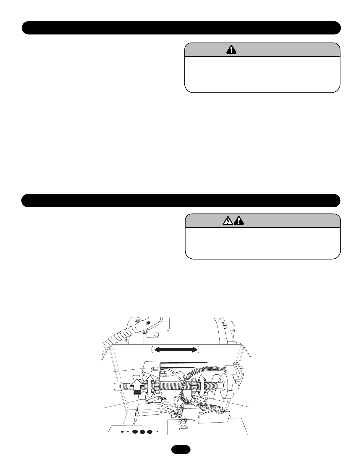
LIMIT SWITCH ADJUSTMENT
NOTE: Make sure the limit nuts are positioned between the limit
switches before proceeding with adjustments.
1. Depress retaining plate to allow nut to spin freely. After
adjustment, release plate and move nut back and forth to
ensure it is fully seated in slot.
2. To increase door travel, spin nut away from limit switch. To
decrease door travel, spin limit nut toward limit switch.
3. Adjust open limit nut so that door will stop in open position
with the bottom of the door even with top of door opening.
4. Repeat steps 1 and 2 for close cycle. Adjust close limit nut so
that the limit switch is engaged as door fully seats at the floor.
INSTALLATION
To reduce the risk of SEVERE INJURY or DEATH, ALWAYS install
reversing sensors when the 3-button control station is out of
sight of door or ANY other control (automatic or manual) is
used. Reversing devices are recommended for ALL installations.
WARNING
WARNING
SAFETY
(Aux. Close) Limit Switch
CLOSE Limit Switch
CLOSE OPEN
OPEN Limit Switch
Page 9
9
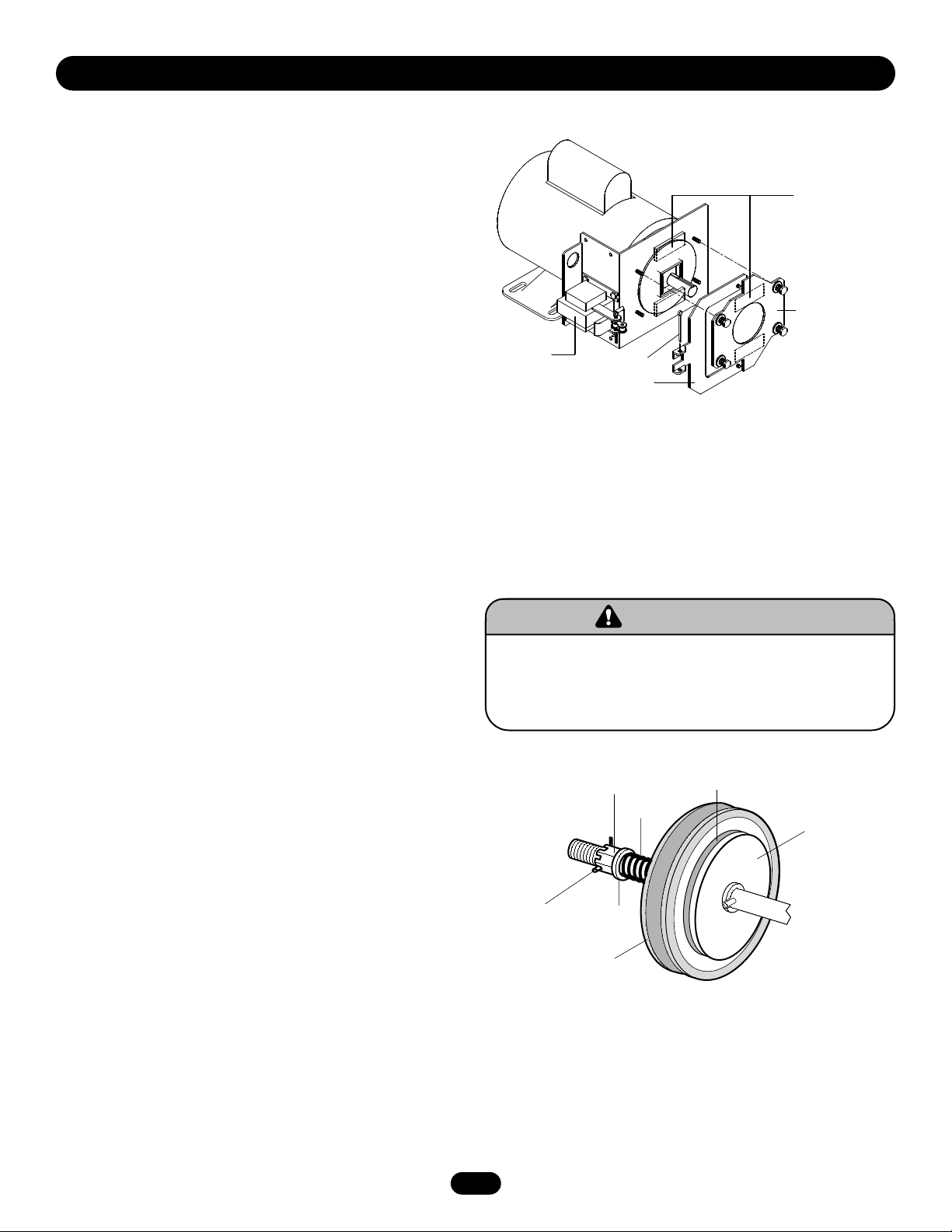
BRAKE ADJUSTMENT
A solenoid brake is available as an option (not included as a
standard feature). The brake is adjusted at the factory and should
not need additional adjustment for the the life of the brake
assembly.
Replace brake assembly when necessary. Refer to the illustration
for identification of components for the solenoid type brake
system.
ADJUSTMENT
CLUTCH ADJUSTMENT AND
AUXILIARY REVERSAL SYSTEM
The Auxiliary Reversal System is designed to protect the door
and motorized operator. It is NOT a substitute for a safety sensing
device. The Auxiliary Reversal System works in tandem with the
adjustable clutch to detect if a closing door runs into or comes
across an obstruction. If an obstruction is met and causes the
clutch to slip, the Auxiliary Reversal System will return the door
to the full open position when closing or stops the door when
opening.
1. Remove cotterpin from nut on the clutch shaft.
2. Back off clutch nut until there is very little tension on the
clutch spring.
3. Tighten clutch nut gradually until there is just enough tension
to permit the operator to move the door smoothly but to allow
the clutch to slip if the door is obstructed. When the clutch is
properly adjusted, it should generally be possible to stop the
door by hand during travel.
4. Reinstall cotterpin.
To prevent possible SERIOUS INJURY or DEATH, install
reversing sensors when the 3-button control station is out of
sight of the door or ANY other control (automatic or manual) is
used. Reversing devices are recommended for ALL installations.
WARNING
WARNING
Brake Assembly
Brake
Plate Assembly
Solenoid
Cotterpin
Release Lever
Adjusting Nut
Clutch Pad
Cotterpin
Spring
Washer
Clutch Pulley
Clutch Plate
Page 10
10
POWER WIRING & GROUND WIRING
To reduce the risk of SEVERE INJURY or DEATH:
• ANY maintenance to the operator or in the area near the
operator MUST NOT be performed until disconnecting the
electrical power and locking-out the power via the operator
power switch. Upon completion of maintenance the area MUST
be cleared and secured, at that time the unit may be returned
to service.
• Disconnect power at the fuse box BEFORE proceeding.
Operator MUST be properly grounded and connected in
accordance with local electrical codes. The operator should be
on a separate fused line of adequate capacity.
• ALL electrical connections MUST be made by a qualified
individual.
• DO NOT install ANY wiring or attempt to run the operator
without consulting the wiring diagram. We recommend that
you install an optional reversing edge BEFORE proceeding with
the control station installation.
• ALL power wiring should be on a dedicated circuit and well
protected. The location of the power disconnect should be
visible and clearly labeled.
• ALL power and control wiring MUST be run in separate
conduit.
WARNING
WARNING
GROUND WIRING CONNECTIONS
1. Connect earth ground to the chassis ground screw in the
electrical box enclosure.
2. Use same conduit entry into the electrical box as the power
wiring.
IMPORTANT NOTE: This unit must be properly grounded. Failure
to properly ground this unit could result in electric shock and
serious injury.
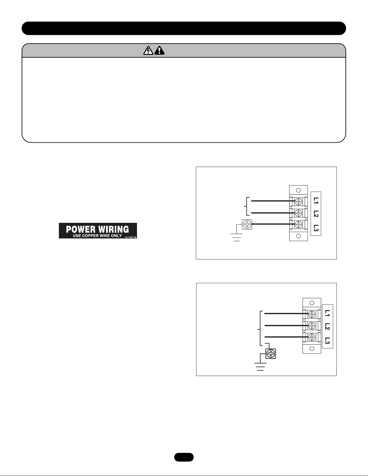
POWER WIRING CONNECTIONS
1. Connect power wires coming from the main to the captive
terminal block in the electrical box enclosure marked with the
label. All power and control wiring must be run in separate
conduit in accordance with local electrical codes.
2. Be sure to run all power wires through the conduit hole in the
electrical box enclosure marked with the label shown below.
NOTE: Must use #14 AWG or thicker wire for power wiring.
ON THREE PHASE MACHINES ONLY: Incorrect phasing of the
power supply will cause the motor to rotate in the wrong
direction. To change motor rotation, exchange incoming power
leads L1 and L2.
Single Phase Power Wiring
Line Power
115/230 Vac
Single Phase
Hot
Neutral
Gnd
Three Phase Power Wiring
Line Power
208/230/380/460/575 Vac
Three Phase
Phase 1
Phase 2
Phase 3
Gnd
Page 11
11
CONTROL STATION WIRING & INSTALLATION
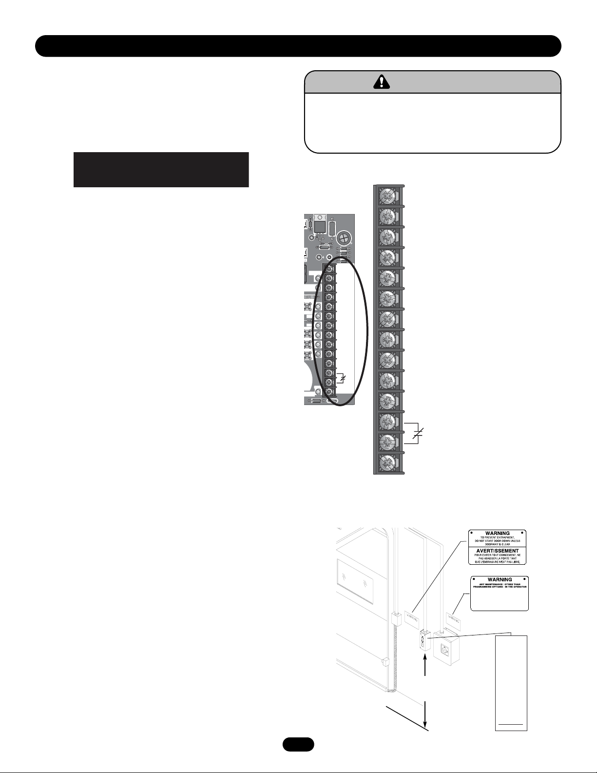
CONTROL WIRING CONNECTIONS
1. Connect control wires to the P1 terminal block located on the
logic board as shown.
2. Connect conduit with all control wires through the conduit
hole in the electrical box enclosure marked with the label
shown below.
3. Apply power to the operator. Press OPEN push button and
observe direction of door travel and then Press the STOP
button.
If door did not move in the correct direction, check for improper
wiring at the control station or between operator and control
station. NOTE: In “Diag” mode the 3-button control station can be
tested to verify correct wiring of Open, Close and Stop buttons
without moving the door.
If the door moves in the wrong direction and or the limits move
in the wrong direction, simply move the motor direction jumper
located on the logic board from the factory default setting (STD)
to the (REV) pins. This will change the motor rotation as well as
the functional position of the OPEN and CLOSE limit switch’s.
Then relocate the safety limit switch (SLS) only to the opposite
side with the new functional close limit location. Orient the arm
(lever) of the limit switch away from the center. NOTE: The motor
direction change is not available on the DJ and DH models.
EXTERNAL RADIO WIRING CONNECTIONS
On all models a radio terminal bracket marked R1 R2 R3 is
located on the outside of the electrical enclosure. In B2 mode the
operator will then open a fully closed door, close a fully open
door, stop an opening door, and reverse a closing door from the
radio remote. In TS control wiring the operator will only open the
door or reset the timer to close. However, for additional door
control from a 3-button remote, a commercial three-channel radio
receiver (with connections for OPEN/CLOSE/STOP) is
recommended.
NOTE: If an external radio receiver is being used in place of the
built-in receiver, remove or disconnect the coaxial cable from the
logic board.
MOUNTING INSTRUCTIONS
1. Mount WARNING NOTICE beside or below the control station.
2. Mount MAINTENANCE ALERT label to either side of control
station.
3. Mount control station(s) within line of sight of door(s).
CONTROL WIRING
USE COPPER WIRE ONLY
40-10032B
To prevent possible SERIOUS INJURY or DEATH, install
reversing sensors when the 3-button control station is out of
sight of the door or ANY other control (automatic or manual) is
used. Reversing devices are recommended for ALL installations.
WARNING
WARNING
4'
Approximate
Control
Station
Optional
Controls
T
D
S
O
24 VOLT AC
24 VOLT AC
TIMER DEFEAT
COMMON
MAINTENANCE ALERT SYSTEM
PHOTO EYES (LiftMaster Only)
REVERSE
OPEN
CLOSE
STOP
COMMON
INTERLOCK
INTERLOCK
SINGLE BUTTON CONTROL
24V
AC
14
24V
AC
TIMER
DEFEAT
CMN
MAS
EYES
EDGE
OPEN
CLOSE
STOP
CMN
SBC
13
12
11
10
9
8
7
6
5
4
3
2
1
C18
DEFEAT
MAS
PEN
LOSE
TOP
OG
D1 E2
ILSAFE
R31
C3
D8
Ø
P1
POWER
TIMER
R8
4
EYES
EDGE
S
IAG
Ø
U7
D31
D7
D6
D5
D4C25
C17
24V
AC
14
24V
AC
D19
D17
D28
D23
D15
D2
Ø
D21
D13
SBC
)
D14
13
TIMER
12
DEFEAT
11
CMN
10
MAS
9
EYES
8
EDGE
7
OPEN
6
CLOSE
5
STOP
4
CMN
3
2
1
SBC
P1
F1
D34
OR IN THE AREA NEAR THE OPERATOR MUST
NOT BE PERFORMED UNTIL DISCONNECTING
THE ELECTRICAL POWER AND LOCKING-OUT
THE POWER VIA, THE MAIN DISCONNECT
SWITCH. UPON COMPLETION OF
MAINTENANCE THE AREA MUST BE CLEARED
AND SECURED, AT THAT TIME THE UNIT MAY
BE RETURNED TO SERVICE.
Maintenance
TM
Alert System
If light is Flashing
Rapidly, it is time
for routine door
maintenance.
If light is Flashing
Slowly, followed
by a pause, call for
immediate service.
Service every
cycles/months
Page 12
12
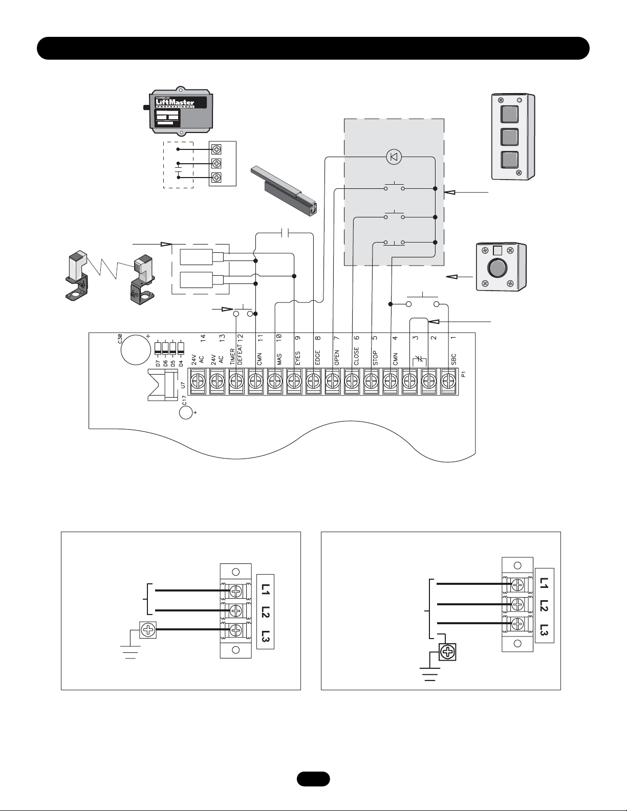
STANDARD POWER & CONTROL CONNECTION DIAGRAMS
OPEN
Radio Control
(24V DC only)
R3
R2
R1
Maintenance
Alert LED
(WH)(RD)
Open
Close
CLOSE
STOP
3-Button
Station
CPS-L &
CPS-LN4
Timer Defeat
Switch
Sensing Edge
Stop
Open/Close
Single Button
Remove Jumper
To Install External
Interlock
Line Power
115/230 Vac
Single Phase
Single Phase Power Wiring Three Phase Power Wiring
Hot
Neutral
Gnd
Line Power
208/230/380/460/575 Vac
Three Phase
Phase 1
Phase 2
Phase 3
Gnd
Page 13

13
LOGIC (VER. 3.0) 1 PHASE WIRING DIAGRAM
OPEN
115V MOTOR CONNECTION 230V MOTOR CONNECTION
NOTE: Gray (GY) and purple (PU) motor wires are reversed
for H and HJ right hand models and all GH and J models.
CPS-L & CPS-LN4
Hoist Interlock
When Present
Ø
C3
R31
D8
657–A
Ø
14GP
Ø
657–A
Ø
14LG
Ø
P4
D31
D7D6D5
U7
C18
R29
E1
(YE) (BL)
Ø
P1
X1
2
Ø
D3
C11
D4C25
C17
TMR DEF
SWITCH
14
24VAC24V
POWER
U1
K3
Maintenance
CLOSE
Alert LED
(RD) (WH)
STOP
Open
3-Button
Sensing
Close
Station
Edge
Stop
Open/Close
Single Button
Remove Jumper
To Install External
9
8
7
6
5
4
3
11
13
12
TIMER
AC
DEFEAT
D19
TIMER
DEFEAT
ØØ
J3
J1
10
MAS
CMN
D17
R8
D25
OLS
EYES
EDGE
OPEN
CLOSE
D23
D15
EYES
DIRECTION
MOTOR
D27
CLS
D16
D1
TIMER
MID
MRT
P7
EDGE
D22
D2ØD21
OPEN
TIMER
ENABLE
3
2
1RADIO
CLOSE
RELAY A
D36
D28
4
MAS
D24
D26
MID
SLS
CMN
STOP
D13
STOP
TTS
RELAY B
D35
C77
C73
2
SBC
FSTSE2
B2 PROG
D1 DIAG
C2
C54
L1
C71
C78
®
1
SBC
P1
D14
)
B2 C2 D1 E2
NON FAILSAFE
(
S8
FAILSAFE
L5
Door Interlock
F1
D34
(YE)
(OR)
(WH)
(YE)
(PU)
(WH)
(RD)
(GY)
(YE)
(RD)
(WH)
(PU)
(YE)
(OR)
(GY)
P6
hot
neutral
ground
115 / 230
VOLT 1PH.
POWER IN
(YE)
NOTE: Lock Sensor is provided on Models
DJ and DH only, red wire from main harness
connects to NC on Bypass L/S and to NO on
Lock Sensor switch. White wires connect the
COM on Bypass L/S and Lock Sensor switch to
NC on Open L/S.
L3 L2 L1
(WH)
MOV
MOV
(WH)
COM
+24 VAC -24 VAC
(WH)
COM
OPEN L/S
COM
BYPASS
L/S
LOCK
SENSOR
(see note at left)
NO
NC
NO
NC
NO
NC
(BK)
120
VAC
(WH)
(RD)
(RD)
(RD)
120 / 240
VAC
(PU)
(WH)
(BR)
(WH)
(YE)
See Motor
Connections
(WH)
COM
NO
CLOSE L/S
NC
NC
SAFETY L/S
NO
COM
NO
COM
COIL
(WH)
C
(GY)
(WH)
01
4
2
(RD)
(YE)
(WH)
1 2 3 4
RPM Board
(YE)
(WH)
B
(WH)
(WH)
8
(WH)
(WH)
6
(WH)
(YE)
(OR)
(PU)
(PU)
01
A
8
4
6
2
(BL) (GY)
See Motor
Connections
(YE)
(WH)
(OR)
(GY)
R1 R2 R3
Radio
Page 14

14
LOGIC (VER. 3.0) 3 PHASE WIRING DIAGRAM
T4
J
T5
J
230V BRAKE
(WHEN PRESENT)
T6
T7 T1
T8
T9 T3
T4
(GY)
(BR)
T2
(PU)
(BR)
(YE)
230V BRAKE
J
T5
J
(WHEN PRESENT)
T6
T7 T1
T8
T9 T3
(GY)
(BR)
T2
(PU)
(BR)
(YE)
(BL/BK)
575V BRAKE
(WHEN PRESENT)
(BL/BK)
1
2
3
208/230V MOTOR CONNECTION 460V MOTOR CONNECTION 575V MOTOR CONNECTION
NOTE: Gray (GY) and purple (PU) motor
wires are reversed for H and HJ right hand
models and all GH and J models.
Sensing
Edge
CPS-L & CPS-LN4
Hoist Interlock
When Present
Ø
C3
R31
D8
657–A
Ø
14GP
Ø
657–A
Ø
14LG
Ø
P4
D31
D7D6D5
U7
C18
R29
E1
(YE) (BL)
Ø
P1
X1
2
Ø
D3
C11
D4C25
C17
TMR DEF
SWITCH
14
24VAC24V
POWER
U1
K3
11
13
12
TIMER
AC
DEFEAT
D19
TIMER
DEFEAT
ØØ
J3
J1
10
MAS
CMN
D23
D28
D17
R8
D25
OLS
4
MAS
D24
D26
MID
SLS
D16
(GY)
(BR)
(PU)
(BR)
(YE)
9
EYES
D15
EYES
DIRECTION
MOTOR
D27
CLS
P7
EDGE
D1
TIMER
MID
MRT
8
EDGE
D2ØD21
OPEN
D22
TIMER
(RD) (WH)
7
6
OPEN
CLOSE
CLOSE
ENABLE
3
RELAY A
2
D36
1RADIO
Maintenance
Alert LED
Open
Close
Stop
5
4
CMN
STOP
D13
STOP
TTS
RELAY B
D35
C77
C73
Open/Close
Single Button
3
2
SBC
FSTSE2
D1 DIAG
C2
C54
L1
C71
C78
®
Remove Jumper
To Install External
Door Interlock
1
F1
SBC
P1
D34
D14
)
(YE)
B2 C2 D1 E2
NON FAILSAFE
(
(OR)
(WH)
(YE)
S8
(PU)
(WH)
(RD)
(GY)
(YE)
B2 PROG
(RD)
FAILSAFE
(WH)
(PU)
(YE)
(OR)
(GY)
L5
P6
OPEN
CLOSE
STOP
3-Button
Station
208/ 230 / 380 / 460
VOLT 3PH.
POWER IN
(YE)
NOTE: Lock Sensor is provided on Models
DJ and DH only, red wire from main harness
connects to NC on Bypass L/S and to NO on
Lock Sensor switch. White wires connect the
COM on Bypass L/S and Lock Sensor switch to
(WH)
NC on Open L/S.
L3 L2 L1
(WH)
COM 120
+24 VAC
COM
OPEN L/S
BYPASS
L/S
LOCK
SENSOR
(see note at left)
MOV
MOV
(WH)
(BK)
VAC
240 / 460 /
575 VAC
-24 VAC
NO
COM
COIL
(WH)
(PU)
(BR)
See Motor
(BR)
Connections
01
B
(WH)
(WH)
(WH)
(WH)
(WH)
NO
(WH)
COM
C
D
COIL
(WH)
(GY)
84
(WH)
62
(WH)
(PU)
(OR)
01
A
4
(GY)
8
62
(YE)
See Motor
Connections
(RD)
(WH)
(RD)
(RD)
(PU)
(WH)
(WH)
(YE)
COM
NO
CLOSE L/S
NC
NC
SAFETY L/S
NO
COM
(RD)
(YE)
(GY)
(WH)
1 2 3 4
RPM Board
(YE)
(WH)
(OR)
R1 R2 R3
Radio
(WH)
NO
NC
COM
NO
NC
NO
NC
Page 15

15
LOGIC BOARD
Auxilliary Board
Connectors
Programmed Chip
Maximum Run
Timer Button
Radio Learn
Button
Mid Stop Learn
Button
Timer to Close
Learn Button
C11
Ø
14LGØ657–A Ø14GPØ657–A
P4
E1
R29
D3
Ø
2
U1
K3
OLS
MID
SLS
D16
P7
C73
C77
MRT
CLS
1RADIO
D36
MID2TIMER
D35
C54
X1
D25
D24
D26
D27
RELAY A
RELAY B
J1
REV
STD
MOTOR
DIRECTION
TIMER
3
ENABLE
TTS
J3
ØØ
CONTACTOR/3 PH
D22
D8
C18
Ø
P1
C17
POWER
D19
TIMER
DEFEAT
D17
R8
D28
MAS
D23
4
SINGLE PHASE
EYES
EDGE
OPEN
CLOSE
STOP
D15
D2
D21
D13
Ø
D1
FSTSE2
D1 DIAG
C71
L1
C2
L5
P6
B2 PROG
FAILSAFE
S8
(
B2 C2 D1 E2
NON FAILSAFE
SBC
)
D14
D34
C78
®
R31
Ø
C3
U7
D31
D7
D6
D5
D4C25
24V
AC
14
Motor Direction
Jumper
Single Phase &
Three Phase Jumper
24V
AC
13
TIMER
DEFEAT
12
Maintenance Alert
System Button for
Programming
CMN
11
MAS
10
EYES
EDGE
OPEN
CLOSE
STOP
CMN
9
8
7
6
5
4
3
Open Button
Close Button
Stop Button
Control Wiring
Terminal Block
2
SBC
P1
1
F1
Wiring Type
Selector Dial
Failsafe Switch
Page 16

16
PROGRAMMING
DETERMINE AND SET WIRING TYPE
Read the descriptions of the different wiring types to determine
which setting will be correct for each application.
SET THE SELECTOR DIAL TO THE DESIRED WIRING MODE:
NOTE: For failsafe wiring you must also set failsafe switch to
FAILSAFE.
TYPE
C2 Momentary contact to open and stop with constant
pressure to close, open override plus wiring for sensing
device to reverse. Programmable mid stop available with
this wiring type. Compatible with 3-Button Station and
1-Button Station.
B2 Momentary contact to open, close and stop, plus wiring
for sensing device to reverse and auxiliary devices to
open and close with open override. Programmable mid
stop available with this wiring type. Compatible with
3-Button Station, 1-Button Station and 1 & 3 Button
Remote Controls.
D1 Constant pressure to open and close with wiring for
sensing device to stop. Compatible with 2-Button.
E2 Momentary contact to open with override and constant
pressure to close. Release of close button will cause
door to reverse (roll-back feature) plus wiring for
sensing device to reverse. Compatible with 3-Button
Station.
SELECTOR DIAL
FAILSAFE SWITCH
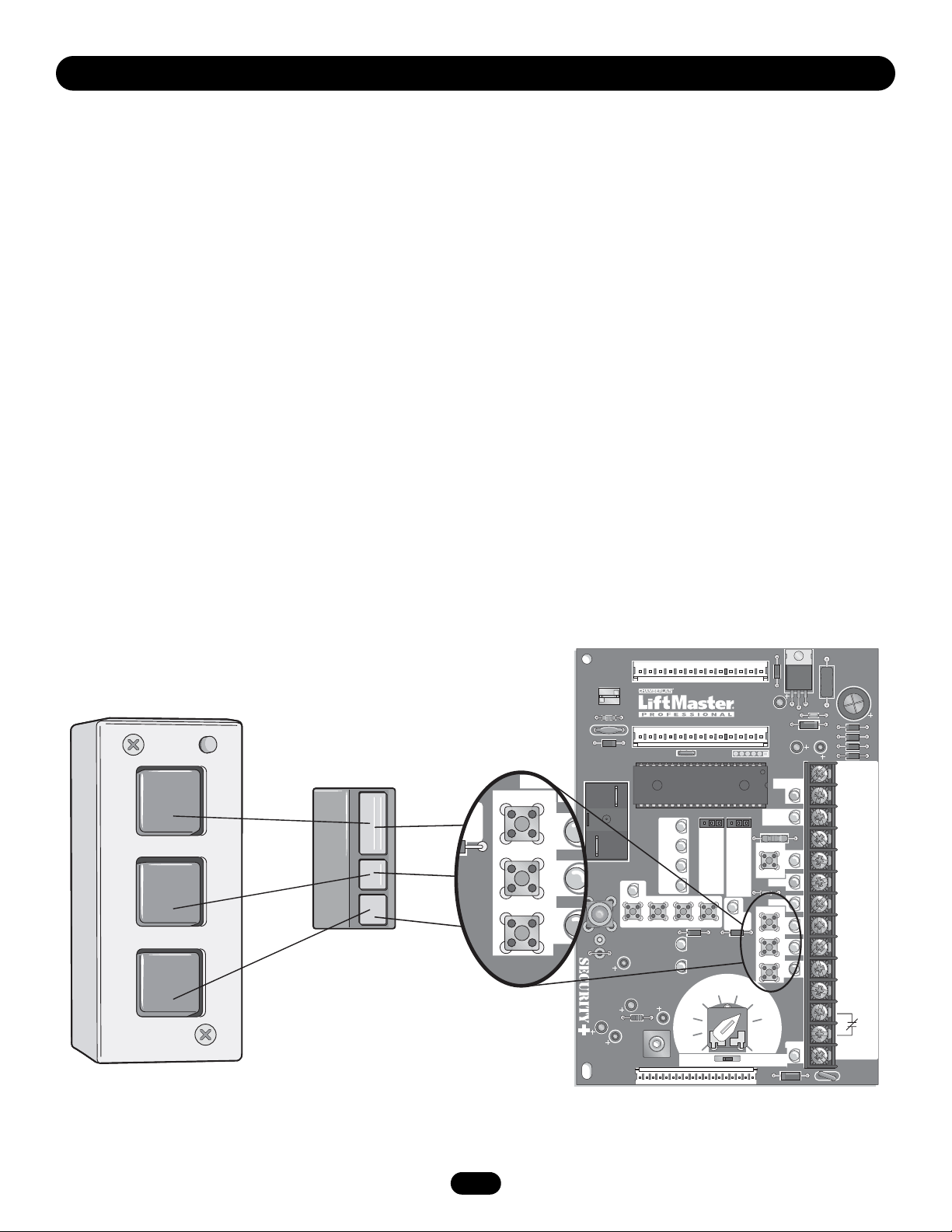
LOGIC CONTROL PUSHBUTTONS OPEN, CLOSE, STOP
Open, Close and Stop buttons are mounted directly on the logic
board. Thus, making it easy to program as well as have door
control at the electrical box. Either the stop control or a jumper
must be wired between terminals 4 and 5 for the on board push
buttons to function.
NOTE: Refer to logic board illustration on page 15 for all
component locations. Before programming the logic board, set
the operators open and close limits. LEDs on the logic board are
provided to assist setting the limits. As each limit is activated the
corresponding LED will light up. The abbreviations are Open
Limit Switch (OLS), Close Limit Switch (CLS) and Sensing Limit
Switch (SLS). Refer to page 8 for limit switch adjustment
instructions.
Page 17

17
PROGRAMMING
FAILSAFE WIRING TYPES
TYPE
TS Momentary contact to open, close, and stop with
open override and Timer To Close. Every device that
causes door to open, including a reversing device,
activates the Timer To Close. Auxiliary controls can
be connected to open input to activate the Timer To
Close. If the timer has been activated, the open
button and radio control can recycle the timer. The
stop button will deactivate the Timer To Close until
the next command input. The Timer To Close will
function from the programmable mid stop with this
wiring type. Compatible with 3-Button Station,
1-Button Station and 1 & 3 Button Remote
Controls. (NOTE: Requires Optional self monitoring
photo eyes to operate.)
T Momentary contact to open, close, and stop, with
open override and Timer To Close. Every device that
causes the door to open, except a reversing device,
activates the Timer To Close. Auxiliary controls can
be connected to open input to activate the Timer To
Close. If the Timer To Close has been activated, the
open button and radio control can recycle the timer.
The stop button will deactivate the timer until the
next command input. The Timer to Close will
function from the programmable mid stop with this
wiring type. Compatible with 3-Button Station,
1-Button Station and 1 & 3 Button Remote
Controls. (NOTE: Requires Optional self monitoring
photo eyes to operate.)
FSTS Momentary button contact for open, close and stop
programming. Radio controls allowing open, close
and stop. User set mid stop. User set Timer To
Close. The single button station opens the door to
the full open limit bypassing the mid stop and
activates the Timer To Close, putting the operator in
TS mode until the door reaches the down limit, or
is stopped in travel. At which time the operator
enters the B2 mode. Compatible with 3-Button
Station, 1-Button Station and 1 & 3 Button
Remote Controls. (NOTE: Requires Optional self
monitoring photo eyes to operate this feature/wire
type.)
C2 Failsafe Same functions as C2. Self Monitoring safety device
must be installed to operate door for each of the
following failsafe wiring types. See Self Monitoring
Safety Device Options. Compatible with 3-Button
Station, 1-Button Station and 1 & 3 Button
Remote Controls.
SELF-MONITORING SAFETY DEVICE OPTIONS
To use the operator in any of the Failsafe wiring modes, or Timer
To Close wiring modes (TS, T, FSTS), a self monitoring safety
device or CPS3 card with photo eyes or safety edges must be
installed.
RECOMMENDED SELF-MONITORING SAFETY DEVICES:
CPS-L NEMA 1 Direct Connect Eyes
CPS-LN4 NEMA 4 Direct Connect Eyes
IMPORTANT NOTES:
1. External interlocks may be used with all functional modes.
2. Auxiliary devices are any devices that have only dry contacts.
Examples: photocell, loop detector, pneumatic or electrical
treadles, radio controls, one button stations, pull cords, etc.
3. Open override means that the door may be reversed while
closing by activating an opening device without the need to use
the stop button first.
B2 Failsafe Same functions as B2. Self Monitoring safety device
must be installed to operate door for each of the
following failsafe wiring types. See Self Monitoring
Safety Device Options. Compatible with 3-Button
Station, 1-Button Station and 1 & 3 Button
Remote Controls.
D1 Failsafe Same functions as D1. Self Monitoring safety
device must be installed to operate door for each of
the following failsafe wiring types. See Self
Monitoring Safety Device Options. Compatible with
2-Button Station and 2-Button Remote.
E2 Failsafe Same functions as E2. Self Monitoring safety device
must be installed to operate door for each of the
following failsafe wiring types. See Self Monitoring
Safety Device Options. Compatible with 3-Button
Station and 3-Button Remote.
Page 18

18
SINGLE BUTTON CONTROL (SBC) REMOTE
This function programs a remote as a wireless single button
control. In B2 mode, operation is OPEN / STOP / CLOSE /
REVERSE / STOP. In C2 mode, operation is OPEN / STOP/
Constant pressure to CLOSE / STOP on release. There is no
operation in D1 mode. In T and TS modes, operation is OPEN /
STOP / CLOSE / REVERSE / STOP and Timer to Close
start/refresh. In FSTS mode, operation is OPEN with Timer to
Close start/refresh only bypassing all up mid stops. Momentary
and constant pressure commands are processed in this function.
1. Press and release the RADIO button on the logic board (LED
will light).
2. Press and release the SBC externally wired button or TIMER on
the logic board (LED flashes rapidly and then remains on
solid).
3. Press and hold the remote button until the LED flashes rapidly.
The LED will then remain on solid after releasing.
4. Press and release the RADIO button on the logic board (LED
flashes rapidly and then turns off). The programming mode is
exited if no activity is performed within 30 seconds.
ERASING REMOTES
Press and hold the RADIO button on the logic board until the
RADIO LED flashes rapidly (approximately 5 seconds).
All remotes will be erased.
Built in 3-channel, 315MHz radio receiver allows you to add as
many as 23 Security✚
®
remotes or dip switch remote controls.
PROGRAMMING REMOTES
STANDARD SINGLE BUTTON REMOTE
1. To enter programming press and release the RADIO button on
the logic board (LED will light).
2. Press and hold the remote button until the LED flashes rapidly,
then release remote button. The LED will then remain on solid
after releasing the button. Repeat to add additional remote(s).
3. Press and release the RADIO button to complete the
programming. The programming mode is exited if no activity is
performed within 30 seconds.
NOTE: Single button remote is not supported with D1 and E2
failsafe wiring modes.
NOTE: Requires self-monitoring photo eyes when using constant
pressure to close (wiring C2, D1 and E2 ).
OPERATION
MODE
B2
C2
D1
E2
T, TS
FSTS
OPEN STOP CLOSE Reverse
Constant
Pressure
Timer To
Close
PROGRAMMING
To prevent possible SERIOUS INJURY or DEATH, install
reversing sensors when the 3-button control station is out of
sight of the door or ANY other control (automatic or manual) is
used. Reversing devices are recommended for ALL installations.
WARNING
WARNING
L
i
f
t
M
a
s
t
e
r
M
Y
Y
MOTOR
E
5
NOTICE: To comply with FCC and or Industry Canada (IC) rules, adjustment or modifications of this
receiver and/or transmitter are prohibited, except for changing the code setting or replacing the
battery. THERE ARE NO OTHER USER SERVICEABLE PARTS.
Tested to Comply with FCC Standards FOR HOME OR OFFICE USE. Operation is subject to the
following two conditions: (1) this device may not cause harmful interference, and (2) this device
must accept any interference received, including interference that may cause undesired operation.
Ø
14LGØ6
P4
E1
R29
C11
D3
Ø
2
U1
K3
X1
D25
OLS
RADIO
P7
C78
®
C71
C73
D16
P6
C77
MID
SLS
CLS
MRT
1RADIO
D36
C54
L1
L5
D24
D26
D27
MID2TI
RELA
RELA
D35
D1
C2
FAILSAF
REV
E2
B2
Page 19
19
OPEN
CLOSE
STOP
Open
Close
Stop
U1
POWER
TIMER
DEFEAT
MAS
4
MRT
1RADIO
MID2TIMER
TIMER
ENABLE
TTS
FSTSE2
RELAY A
RELAY B
D1 DIAG
C2
B2 PROG
3
24V
AC
24V
AC
TIMER
DEFEAT
CMN
MAS
EYES
EDGE
OPEN
CLOSE
STOP
CMN
SBC
11
10
9
14
13
12
8
7
6
5
4
3
2
1
CLOSE
STOP
OPEN
EDGE
OLS
MID
SLS
MOTOR
DIRECTION
REV
STD
CLS
D25
D24
D26
D27
D36
C77
C73
C54
C78
L1
L5
P6
D35
S8
D16
P7
EYES
K3
P1
D34
F1
FAILSAFE
(
B2 C2 D1 E2
)
NON FAILSAFE
D23
D15
D1
D22
R8
J1
X1
E1
R29
C18
D8
U7
R31
D31
C3
Ø
D7
D6
D5
D4C25
C17
C11
D3
Ø
2
P1
Ø
P4
Ø
14LGØ657–A Ø14GPØ657–A
J3
ØØ
D2
Ø
D21
D13
D14
D28
D17
D19
CONTACTOR/3 PH
SINGLE PHASE
SBC
C71
®
CLOSE
STOP
OPEN
EDGE
D1
D22
D2
Ø
D21
D13
Your 315MHz Security✚®or dip switch remote control can be
programmed to operate as a 3-button wireless control station:
the large button will open the door, the middle button will close
the door, and the third button will stop the door’s movement.
You may set up this feature as follows:
1. To enter programming press the RADIO button on the logic
board (the RADIO LED will light).
2. To program the OPEN button to a remote control press the
OPEN button on the logic board. The RADIO LED will flash and
then stay on solid. Then press the corresponding button on the
remote control. The RADIO LED on the logic board will flash,
this confirms that the remote control has been programmed.
(By programming the remote you use 1 channel of the 23
channels on the radio receiver.)
3. To program the CLOSE button to a remote control press the
CLOSE button on the logic board. The RADIO LED will flash
and then stay on solid. Then press the corresponding button
on the remote control. The RADIO LED on the logic board will
flash, this confirms that the remote control has been
programmed. (By programming the remote you use 1 channel
of the 23 channels on the radio receiver.)
PROGRAMMING
4. To program the STOP button to a remote control press the
STOP button on the logic board. The RADIO LED will flash and
then stay on solid. Then press the corresponding button on the
remote control. The RADIO LED on the logic board will flash,
this confirms that the remote control has been programmed.
(By programming the remote you use 1 channel of the 23
channels on the radio receiver.)
5. After learning remote controls press the RADIO button on the
logic board (LED will turn off). NOTE: If no activity within 30
seconds the radio will automatically exit programming mode.
Page 20
20
PROGRAMMING
MAINTENANCE ALERT SYSTEM (MAS)
Feature: An internal cycle counter will activate a flashing LED on
the 3-button control station when the preset number of cycles or
months has elapsed (whichever occurs first). Setting this feature
is optional. By default this feature will never activate. Logic 3.0
operators incorporate a self diagnostic feature built into the MAS
LED. In addition to indicating when routine maintenance is due,
the MAS LED can be used to troubleshoot some problems with
the operator.
Benefit: The Maintenance Alert System (MAS) assists the
installing dealer in setting up a routine maintenance program.
Once programmed, the MAS notifies the end user (with a flashing
LED on the 3-button station) when a preset number of
cycles/months has elapsed and scheduled maintenance is due.
To Program:
1. The Maintenance Alert System (MAS) assists the installing
dealer in setting up a routine maintenance program. Once
programmed, the MAS notifies the end user (with a flashing
LED on the 3-button station) when a preset number of
cycles/months has elapsed and scheduled maintenance is due.
2. Close the door.
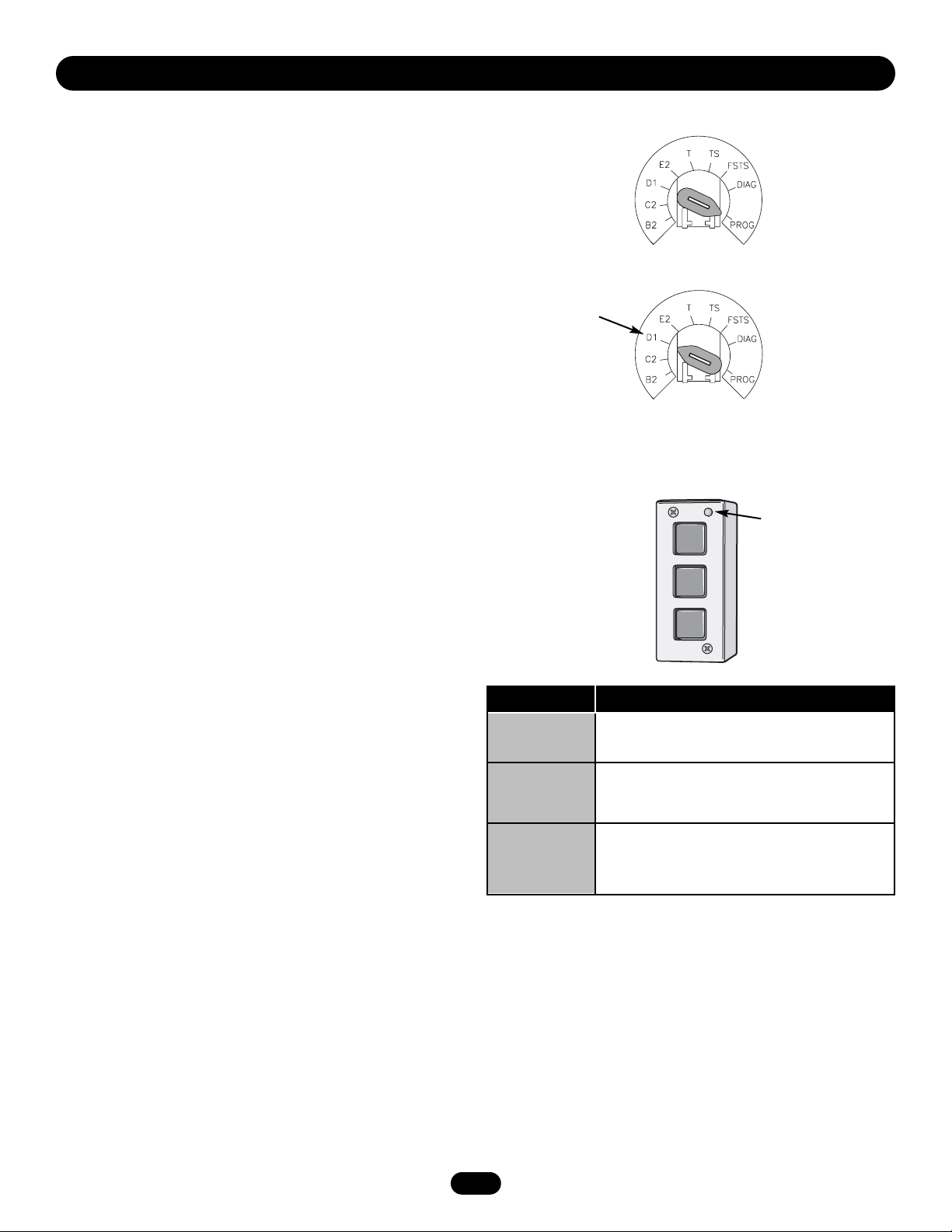
3. Turn the selector dial to PROGRAM.
4. Press and release the MAS SET button.
5. Press the STOP button once to clear the MAS counter.
6. Press the OPEN button once for every 5,000 cycles
increments. Press the CLOSE button once for every 3 month
increments. Press the STOP button once to clear the MAS
memory.
7. Press the MAS SET button to complete the programming. The
on board LED will flash back the programmed settings. The
OPEN LED will flash once for every 5,000 cycles. The CLOSE
LED will flash once for every 3 months.
8. Turn the selector dial back to the desired wiring type.
NOTE: If MAS LED flashes 2 or more flashes in a row followed by
a pause, an operator error occurred. Turn to page 27 to diagnose
problem.
Example: A door is installed with 30,000 cycle springs and has
an annual service contract. To set the MAS, turn selector dial to
PROGRAM, press MAS button, press the STOP button to clear
the memory and then press the OPEN button 6 times (30,000
cycles) and close 4 times (12 months). Press the MAS again to
complete the programming. Set the selector dial to desired wiring
type.
Special Notes about MAS: A 5th wire must be run to the control
station to activate the MAS LED. The MAS LED on the logic board
is always enabled. When the operator is serviced after the MAS
LED has started to flash, repeat the setup procedure to program
in the number or cycles desired until the next service visit OR
press and hold the MAS button for 5 seconds in the PROGRAM
mode to reset the MAS with its current programmed value. To
disable the MAS, follow the programming procedure above and
press the STOP button to reset the counter to zero. Every time
the operator leaves the close limit is counted as one cycle.
To view how many cycles are programmed into the MAS, set the
Operation will vary
depending on
wiring type
SELECTOR DIAL
OPEN
CLOSE
STOP
Adds 5,000 cycles to Maintenance Alert System
Activation Counter.
Adds 3 Months to Maintenance Alert System
Activation Timer.
Clears memory, sets Maintenance Alert System
Activation Counter to 0 cycles and
0 months.
Press This To Get This
3-BUTTON STATION
Maintenance
Alert LED
selector dial to DIAGNOSTIC and press the MAS button. The
OPEN button LED will flash once for every 5,000 cycle increment
programmed and the CLOSE button LED will flash once for every
3 month increment programmed.
To view how many cycles have elapsed since the last time the
MAS was programmed, set the selector dial to “Diagnostic” and
press the “MAS” button. Press the OPEN button; the OPEN LED
will flash once for every 5,000 cycles that has elapsed. Press the
CLOSE button; the CLOSE LED will flash once for every (3)
months that has elapsed. Press the MAS button to exit.
OPEN
CLOSE
STOP
Page 21

21
Operation will vary
depending on
wiring type
SELECTOR DIAL
Operation will vary
depending on
wiring type
SELECTOR DIAL
PROGRAMMING
OPEN MID STOP
Feature: The mid stop feature is to open the door to a preset point
prior to the fully open position.
Benefit: The door opens to a midpoint between open and close
reducing heating and cooling costs. The door will not cycle fully,
providing longer door and operator life.
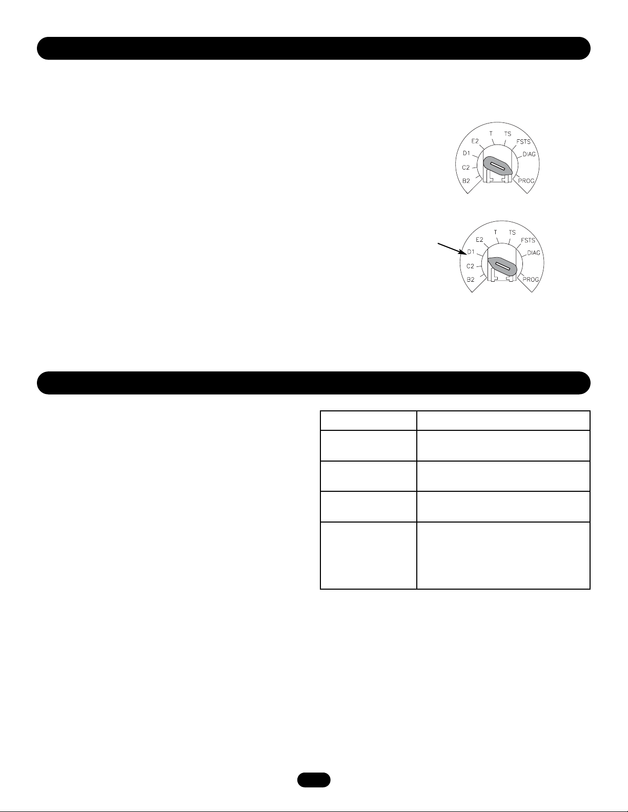
To Program:
1. Close the door.
2. Turn selector dial to “PROGRAM.”
3. Press the “MID SET” button on logic board.
4. Press the OPEN button, wait until the door reaches the desired
mid stop height, then press the STOP button.
5. Press the MID SET button to complete programming.
6. Turn selector dial back to desired wiring type.
NOTE: A momentary open command will open the door fully from the
“Mid Stop” position. Once at the “Mid Stop,” Photo eyes and other
safety devices will not open the door beyond the mid stop position,
except in E2 mode. The Timer to Close will work from the Mid Stop.
To clear the Mid Stop set the selector dial to Program and press and
hold the MID SET button for 5 seconds. The MID SET LED will flash
rapidly and turn off once the Mid Stop has been cleared.
DOWN MID STOP
A new feature is the down mid stop which can be enabled with the
purchase of the red/green light kit (RDGRNCARD). See kit
instructions of how to enable this new feature.
TIMER TO CLOSE
Feature: Timer automatically closes door after preset time. All safety
devices must be unobstructed.
Benefit: The door will automatically close after pre set amount of
time. Great for apartment buildings, fire stations and other
applications where the end user wants the door to close
automatically after a specified amount of time.
Requirements: Must have at least one of the following safety devices
attached: CPS-L, CPS-LN4 or CPS3 card with valid safety device.
Wiring type must be set to TS, T or FSTS.
TO PROGRAM MANUALLY (Method 1):
1. Close the door.
2. Turn the selector dial to PROGRAM.
3. Press the TIMER button on the logic board.
4. Press the STOP button to clear the timer.
5. Press the OPEN button for every 5 seconds the operator should wait
before attempting to close the door. Press the CLOSE button for
every 60 seconds the operator should wait before closing the door.
6. Press the TIMER button to complete programming. The
OPEN/CLOSE button LEDs will flash to confirm the timer setting.
The OPEN LED will flash once for every 5 seconds programmed and
the CLOSE LED will flash once for every 60 seconds programmed.
7. Turn the selector dial to desired timer wiring type (TS ,T or FSTS).
Example: To close the door after 70 seconds. Turn selector dial to
Program, press the TIMER button, press the STOP button to clear the
timer, Press the CLOSE button once for 60 seconds and press the
OPEN button twice for 10 seconds. Press the TIMER button to finish
programming the timer. Turn selector dial to desired Timer wiring type.
(TS, T, FSTS).
To reduce the risk of SEVERE INJURY or DEATH, ALWAYS install
reversing sensors when the 3-button control station is out of
sight of door or ANY other control (automatic or manual) is
used. Reversing devices are recommended for ALL installations.
WARNING
WARNING
Page 22

22
TIMER TO CLOSE
PROGRAM TIMER TO CLOSE BY EXAMPLE (Method 2):
To Program:
1. Close the door.
2. Turn the selector dial to PROGRAM.
3. Press and hold TIMER button for 5 seconds until TIMER LED
flashes.
4. Press the OPEN button and wait for the door to reach full open or
mid stop position.
5. Wait for desired amount of time to pass. (An internal stop watch
starts counting when the door stops moving.)
6. Press the TIMER button or CLOSE button to stop the timer.
(TIMER SET LED will turn on.)
7. Turn the selector dial to the desired wiring type.
Example: The door should close 15 seconds after a truck enters a
garage. To program the Timer to Close, turn the selector dial to
PROGRAM, press the TIMER button until the TIMER LED blinks,
press the OPEN button and wait until the door reaches the open
position, wait for the truck to pass through, count 15 seconds and
then press the CLOSE button.
NOTES: To read back the Timer to Close setting, turn the selector
dial to Diagnostic and press the TIMER button. The OPEN LED will
flash once for every 5 seconds programmed and the CLOSE LED
will flash once for every 60 seconds programmed.
To deactivate the timer from the open position press the STOP
button. The timer will be reactivated on the next operation
command. To deactivate the timer for more than one cycle, attach a
switch to 11 and 12 (Common and Timer Defeat).
All timer modes require a supervised safety device to be installed.
Reminders: FSTS wiring mode allows the Timer to Close to be
activated by the Single Button Control (terminal 1) only. T wiring
mode allows the door to attempt to close only one time for safety
purposes.
Operation will vary
depending on
wiring type
SELECTOR DIAL
AUTOMATICALLY LEARNED PROGRAMMING
AUXILIARY REVERSAL SYSTEM / RPM SENSOR
Feature: This feature utilizes the RPM sensor connected to the
logic board to detect when the clutch slips and reverses the door
(clutch must be properly adjusted). In addition, the RPM
eliminates the need for a centrifugal switch on 1/3 and 1/2
horsepower single phase motors.
Benefit: The Auxiliary Reversal System reverses the operator
upon hitting an obstruction, preventing excessive door and
operator damage. We require the use of safety devices for
primary safety protection. By removing the centrifugal for 1/3 and
1/2 horsepower single phase motors, the leading cause of motor
failures is eliminated. (Auxiliary Reversal System not applicable
on models GH and GT.)
NOTE: This feature is automatically learned and does not require
programming.
PROGRAMMING
OSE OPEN
RPM Sensor
Logic Board
Page 23
23
MAXIMUM RUN TIMER (MRT)
Feature: The operator can learn the time it takes to open or close
the door plus an additional 10 seconds.
Benefit: If the operator does not meet its open or close limit
within the set time it will stop, limiting damage to the door and
operator.
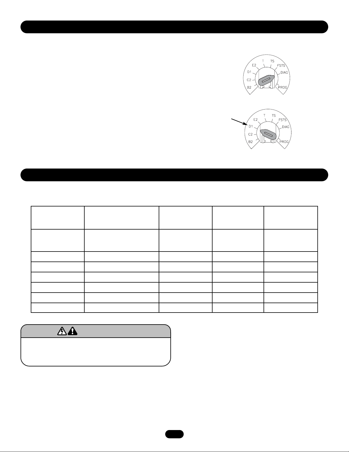
To Program:
NOTE: The default setting for the MRT is 90 seconds. In the event
the application requires the MRT be manually learned for a longer
duration follow steps below.
1. Start with the door in the closed position.
2. Set the selector dial to “PROGRAM.”
3. Press MRT button on logic board.
4. Press the OPEN button and wait for the door to reach the full
open limit.
5. Once the door has reached the open position, programming is
complete.
6. Turn dial to desired wiring type.
NOTE: To reset MRT only, turn selector dial to program and press
and hold the MRT button until the MAS led flashes rapidly.
Operation will vary
depending on
wiring type
SELECTOR DIAL
OPTIONAL PROGRAMMING
RED/GREEN WARNING LIGHT CARD
Feature: The Red/Green warning light card flashes a warning light
for 10 seconds prior to the Timer to Close activating the door to
close.
Benefit: Advanced warning of the door closing helps prevent
traffic collisions with the door.
Light Control Module Operation: The green lights on the OPTION
BOARD will turn on if the board is seated properly and the power
is on. When the door reaches the full open limit or mid stop, the
timer circuit and the green lamp holder will be activated. (Green
lamp will not be activated if timer setting is less than 10
seconds.) The red lamp holder will receive power as indicated at
right.
Requirements: Must have the LiftMaster Red/Green warning light
kit RDGRNCARD and must have at least one of the following
safety devices attached: CPS-L, CPS-LN4 or CPS3. See
Red/Green warning light instructions for further details.
TIMER SETTING RED LAMP HOLDER RECEIVES POWER
Timer setting equals
zero
Activates when the door closes and until
close limit is activated
Greater than 10
seconds
10 seconds before door starts to close
and until close limit is activated
Less than or equal to
10 seconds
Activates when the door reaches the
open limit or mid stop
The red lamp holder receives power
when the door opens and remains
activated if the door is stopped manually
before reaching the mid stop or the open
limit
AUTOMATICALLY LEARNED PROGRAMMING
Page 24
24
RESETTING FACTORY DEFAULTS - CLEARING MEMORY
To reset most of the user installed settings back to factory
defaults:
1. Turn the selector dial to DIAGNOSTIC.
2. Press and hold the STOP button for 5 seconds. The MAS LED
will flash momentarily when the factory defaults have been
restored.
3. Return the selector dial to the desired wiring type.
Factory Defaults:
a. Timer to close = 0 seconds
b. CPS-L photo eyes = unlearned
c. The Mid Stop is deactivated
d. The Maintenance Alert System is deactivated
e. The Maximum Run Timer is set to 90 seconds
Operation will vary
depending on
wiring type
SELECTOR DIAL
MAINTENANCE SCHEDULE
For use with Maintenance Alert System.
Check at the intervals listed in the following chart:
HOW TO ORDER REPAIR PARTS
OUR LARGE SERVICE ORGANIZATION SPANS AMERICA
Installation and service information
are available 6 days a week.
Call our TOLL FREE number:
1-800-528-2806
Monday through Friday 5 a.m. to 6 p.m. (MST)
Saturday 7 a.m. to 3:30 p.m. (MST)
OPTIONAL PROGRAMMING
Use SAE 30 Oil (Never use grease or silicone spray).
• Do not lubricate motor. Motor bearings are rated for
continuous operation.
• Do not lubricate clutch or V-belt.
Repeat ALL procedures.
Inspect and service whenever a malfunction is observed or
suspected.
To avoid SERIOUS PERSONAL INJURY or DEATH from
electrocution, disconnect ALL electric power BEFORE
performing ANY maintenance.
WARNING
WARNING
ITEM
Drive Chain
Sprockets
Clutch
Belt
Fasteners
Manual Disconnect
Bearings and Shafts
PROCEDURE
Check for excessive slack.
Check and adjust as required.
Lubricate.
Check set screw tightness.
Check and adjust as required.
Check condition and tension.
Check and tighten as required.
Check and operate.
Check for wear and lubricate.
EVERY 3 MONTHS
OR
5,000 CYCLES
EVERY 6 MONTHS
OR
10,000 CYCLES
EVERY 12 MONTHS
OR
20,000 CYCLES
Page 25

25
DIAGNOSTIC CHART
The logic board has several LEDs to assist in the installation and troubleshooting of the operator. The following chart should assist in
verifying the operator is functioning properly. Turn the selector dial to DIAGNOSTIC to keep the door from moving while
troubleshooting.
TROUBLESHOOTING
Power Green Indicates that power is being generated for the logic board.
Stop Green Indicates a closed circuit between common and terminal 5.
Pressing stop should turn off this LED.
Open Yellow Indicates a closed circuit between common and terminal 7.
Pressing the open button should turn ON this LED.
Close Yellow Indicates a closed circuit between common and terminal 6.
Pressing the close button should turn ON this LED.
Eyes Green Solid on indicates photo eyes learned. Flashing indicates photo
eyes need to be connected or obstructed. Solid off indicates no
eyes learned.
Timer Defeat Yellow Solid on indicates a closed circuit between common and terminal
12. Timer to close will not close.
OLS Yellow Pressing the Open Limit Switch should turn ON this LED.
CLS Yellow Pressing the Close Limit Switch should turn ON this LED.
SLS Yellow Pressing the Sensing Limit Switch should turn ON this LED.
Edge Yellow Indicates a closed circuit between common and terminal 8.
Pressing the edge should turn ON this LED.
Mid Stop Yellow Solid on indicates door is stopped on up or down mid stop.
Flashing indicates MID STOP is being set.
Timer Enabled Green Solid on indicates TIMER is programmed and will activate from
open or mid stop position. Flashing indicates Timer is counting
down and door will close after preset time.
SBC Yellow Indicates a closed circuit between common and terminal 1.
Pressing the single button control station should turn ON this LED.
MAS Yellow Indicates the Maintenance Alert System has been activated or an
error code has been triggered.
Relay A Yellow Indicates open or close command has been given to the motor.
LED turns on when OPEN/CLOSE button is pressed.
Relay B Yellow Indicates open or close command has been given to the motor.
LED turns on when OPEN/CLOSE button is pressed.
LED COLOR DEFINITION
Page 26

26
TROUBLESHOOTING GUIDE
THE OPERATOR WILL
NOT RESPOND TO ANY
COMMANDS
POWER LED IS NOT ON
STOP BUTTON LED IS
NOT ON
THE DOOR WILL MOVE
ABOUT A FOOT THEN
STOP. AFTER STOPPING,
ONLY CONSTANT
PRESSURE COMMANDS
WILL MOVE THE DOOR
THE DOOR WILL MOVE
MOST OF THE WAY
TOWARDS A LIMIT THEN
STOP. AN EXTRA OPEN OR
CLOSE COMMAND IS ABLE
TO GET DOOR TO
COMPLETE CYCLE
THE DOOR WILL OPEN
SOME BUT NOT
COMPLETELY. AN EXTRA
OPEN IS ABLE TO GET THE
DOOR TO OPEN
COMPLETELY
THE DOOR WILL OPEN BUT
WILL ONLY CLOSE AFTER
A FIVE SECOND DELAY
WITH CONSTANT
PRESSURE ON THE CLOSE
BUTTON
a) No power supply
➤ Verify primary line voltage from power source.
b) Operator control station is wired wrong
➤ Use the OPEN, CLOSE and STOP LEDs to help check correct wiring.
Verify that the board is accepting commands by using the onboard
station. Green light next to stop button must be on.
c) Interlock switch is activated
➤ Check Interlock(s). If more than one external interlock is present they
must be wired in series.
d) Dial still in programming or diagnostic
➤ Set dial to desired wiring type.
mode
e) Motor is malfunctioning
➤ Verify proper voltage getting to the motor (Check motor name plate).
f) Motor thermal overload tripped
➤ Check for obstructions and verify the door moves freely. Cycle operator
in constant pressure one full cycle open and close to reset fault. Check
to see if motor is hot. Allow motor to cool before attempting to move
door.
g) Failsafe switch is activated requiring
➤ Move switch to non-failsafe or connect a failsafe sensing device.
photo eyes
h) Off Board relay may need to be
➤ When the OPEN or CLOSE button is pressed, Relay A or B LED should
replaced see wiring diagram turn on and the door should move in the corresponding direction. If
Relay A or B lights and the door does not move, off board relay may
need to be replaced (see wiring diagram Off Board Relays).
i) Possible accessory malfunction
➤ Disconnect all devices, reattach them one at a time testing for a failure
after each one is replaced.
j) Possible logic board failure
➤ Replace logic board.
a) Control station not connected or wired
➤ Check wiring to control station.
correctly
b) Interlock switch
➤ Check interlock switch(es) for continuity.
a) The photo eyes, edge or other sensing
➤ If the on board EYES LED is flashing, the photo eyes are misaligned or
device is obstructed or activated not connected. Remove any obstructions, check the safety device wires
for continuity and shorts.
b) The logic board thinks that the direct
➤ Unlearn the photo eyes from the memory by resetting factory defaults.
connect photo eyes are attached and
blocked
c) Failsafe switch set
➤ Slide switch to Non-Failsafe mode.
FAULT POSSIBLE CAUSE FIX
RPM sensor is not connected properly ➤ Check the RPM assembly for loose connections. Check that RPM wheel
or may need to be replaced is turning when operator is running. Check for foreign matter blocking
optical lens.
➤ Replace RPM sensor.
The Maximum Run Timer is not set
➤ Manually reprogram the Maximum Run Timer (see page 23).
correctly OR reset the factory defaults (see page 24).
There may be a Mid Stop set
➤ Check to see if the Mid Stop LED is on. Clear the Mid Stop by turning
the selector dial to program. Press and hold the MID STOP button for
5 seconds. Return dial to desired wiring type.
a) Loose secondary wiring connections
➤ Repair or replace connections or control transformer.
or a faulty control transformer
b) Logic board failure
➤ Replace logic board.
c) Interlock switch
➤ Check interlock(s).
Page 27

27
TROUBLESHOOTING ERROR CODES
Logic 3.0 operators incorporate a self diagnostic feature built into
the MAS LED. In addition to indicating when routing maintenance
is due, the MAS LED can be used to troubleshoot some problems
with the operator.
If the MAS LED is flashing on and off rapidly, the Maintenance
Alert System has been triggered and the schedule operator
service is due. If the MAS LED flashes 2 or more pulses in a row
ERROR CODE DESCRIPTION EFFECT DISPLAY CORRECTION
E1 MAS triggered (cycles or months) None normal operation. 1 blink Reset MAS.
E2 No RPM input during opening or closing The door only responds to 2 blinks Clutch is slipping,
constant pressure commands. adjust clutch, or verify RPM
sensor connection or replace
RPM sensor.
NOTE: To relearn the RPM
sensor, move the door with a
constant pressure command.
The door will stop once
relearned and normal
operation will resume.
E3 (MRT) Maximum Run Time timed out The door stops before reaching 3 blinks First check Operator
the desired time. for any faults (i.e., Bad Limit
switch), manually learn Max
Run Timer (see page 23)
OR reset factory defaults
(see page 24).
E4 Obstruction sensed on closing Operator will be in the OPEN 4 blinks Cleared by removing
position. obstruction or realigning
photo eyes and giving a close
command.
E5 Stuck key button pressed for greater than Stuck key on 3-button station 5 blinks Stuck key must be
2 minutes. will not respond. unstuck before it will be
recognized as an input.
E6 Rotary dial in invalid position for greater The door will not respond to 6 blinks Rotary dial must be
than 30 seconds. the 3-button station or any set to a valid position.
other input.
E7 Failsafe Safety device faulted or not Normal operation (5 second 7 blinks Cleared when safety
connected for greater than 2 minutes constant pressure override device is cleared or
required to close). connected.
E8 Brownout Detected Operator will run as long as 8 blinks 1. Check AC line for
enough power is present. voltage.
2. Check transformer
secondary for low voltage. To
many accessories may be
connected to the transformer.
E9 Motor movement at invalid time Operator will continue to Flash on start Check relays and the
function normally for 5 operations of movement drive circuitry to insure
and then default to a constant that they are turning off.
pressure mode. Operator must run correctly
for two starts for the error to
be cleared.
followed by a pause, an operator error has occurred. To view how
many errors currently exist, turn the selector dial to DIAGNOSTIC
and press the OPEN button. To read out each individual error
code (if more than one exists) press CLOSE. It is possible to have
more than one error at a time.
The chart below can assist with identifying the flashes on the
MAS LED.
NOTES: Error codes take priority over normal MAS LED operation. Error codes will repeat on the MAS every 1.5 seconds until cleared.
There may be more than one error present, but only the highest priority will flash. If the highest error is cleared, the next highest will
flash. All errors self-correct when the corrective action is taken and a reset is not needed.
Page 28

28
TROUBLESHOOTING RADIO FUNCTIONALITY
The error codes will display at the radio LED.
NOTE: Radio receiver is compatible with 315MHz remotes
ERROR CODE SYMPTOM DISPLAY POSSIBLE PROBLEM CORRECTION
R1 No response from the remote Quick Flash Unlearned remote - Try re-learning the
A user tries to use a remote, remote (page 18).
but the RADIO LED only flashes
briefly and there is no response
from the operator.
R2 No response from the remote No LED Cannot recognize remote - Replace battery - OR -
activity A weak signal caused by a eliminate interference - OR-
discharged battery or outside obtain a qualified remote.
interference with the radio
- OR - the radio being
learned is not compatible
with the operator.
R3 The remote cannot be learned Radio LED Cannot recognize remote - Replace battery - OR -
turns off after A weak signal caused by a eliminate interference - OR30 seconds discharged battery or outside obtain a qualified remote.
interference interfering with the
learn process - OR - the radio
being learned is not compatible
with the operator.
R4 The remote cannot be learned 2 Blinks No free records - Erase all learned remotes
A user enters RADIO function and re-learn the desired
learning mode but there is no remote.
space left to add another remote.
R5 The remote cannot be learned 3 Blinks Duplicate remote - This remote already has a
A user enters RADIO function function associated with it. To
learning and selects the function change the function, erase all
to be learned. When the remote learned remotes and
button is pressed for learning, re-learn the desired remote
a search reveals that remote
is already learned.
R6 Cannot close via constant pressure in IR LED flashes No safety device present - Obtain direct connect eyes or
C2, D1 or E2 modes. A safety device is required to a CPS3 device - OR - change
close via constant pressure. to a mode that does not
require constant pressure.
Page 29

29
This page intentionally left blank.
Page 30

30
ELECTRICAL BOX
(K72-12515-1)
(K72-14130-1)
7
5
8
1
4
2
11
3
K2
9
6
10
K1
Page 31

31
ELECTRICAL BOX LOGIC (VER. 3.0)
For replacement of electrical box, motor or brake components be sure to match model number of your unit to kit number below to
ensure proper voltage requirements.
INDIVIDUAL PARTS
ITEM PART # DESCRIPTION
1 K75-32269 Cover
2 21-14182 Transformer, 115/230V
21-5460 Transformer, 460V
21-5575 Transformer, 575V
3 29-31244 Relay 24Vdc DPST - (A & B relay)
all operators
4 29-31245 Relay 12Vdc SPDT - (C & D relay)
3 Phase only
29-31229 Relay 24Vdc SPDT - (C relay)
1 Phase only
5 K74-31243 MOV 580V
6 K79-15016-1 RPM sensor assembly
7 K1A5729 Logic board-Logic 3
8 K2A761 Coaxial cable
9 K1C3196-3 Antenna
10 13-10024 Limit Nut
11 23-10041 Limit Switch
SERVICE KITS
ITEM PART # DESCRIPTION
K1 K72-14130-1 Limit shaft kit
Complete with: Limit shaft, limit nuts,
limit bearings, limit sprocket,
interrupter cup, shim washers,
compression ring, roll pin,
and e-rings.
K2 K72-12515-1 Limit switch kit
Complete with: Limit nut retainer,
switch plates, backup plate, depress
plates, limit switches, standoffs,
screws, and locknuts.
*To order a complete electrical box kit, add a K- prefix to the
model number of your operator. For example:
H5011L3 (Operator) = K-H5011L3 (Electrical box kit)
*Non stocked item. Please allow additional delivery time.
Page 32

32
MODEL J
14
(K72-19975)
(K72-19974)
16
15
6
6
K1
2
1
4
7
2
3
5
13
11
9
K2
3
12
8
10
Page 33

33
REPAIR PARTS KITS - MODEL J
SERVICE KITS
ITEM PART # DESCRIPTION
K1 K72-19975 Clutch shaft kit
Complete with: Clutch shaft, 1"
keyed flange bearings, dual sprocket
32/14, splined core sprocket, e-ring,
compression spring, pulley
assembly, washers, thrust bearing,
retaining ring, splined hub, and roll.
K2 K72-19974 Output shaft kit
Complete with: Output shaft,
sprocket assembly, dual sprocket
32/14, sprocket 48B18 X 1" bore,
sprocket 50B12 X 1" bore, ring,
washers, set screw, roll pin, and
thin walled receiver.
NOT SHOWN
71-B120H Brake kit - 115 Volt models
71-B240H Brake kit - 230-460 Volt models
71-B575H Brake kit - 575 Volt models
Complete with: Brake hub kit, brake
release lever, brake disk, spring cup,
studs, compression springs, brake
solenoid, solenoid cover, spacers,
mounting plate, pressure plate,
feather key, and conduit.
INDIVIDUAL PARTS
ITEM PART # DESCRIPTION
1 11-19470 Clutch shaft - J
2 12-19504 Keyed flange Bearing 1"
3 15-19480 Dual sprocket 32/14
4 15-19484 Splined core sprocket
5 18-30957 Compression spring
6 75-19985 Pulley assembly
7 80-19846 Splined hub, J disconnect
8 15-19478 Sprocket assembly
9 15-48B18LGE Sprocket 48B18 X 1"
10 15-50B12LGH Sprocket 50B12 X 1"
11 16-5L304 Cogged Belt 30.4"
12 K75-19978-L Frame kit (LH)*
13 K75-19978-R Frame kit (RH)*
14 K75-19977 J Arm kit
15 17-6014 Motor pulley
16 K20-1033B-LP2 Motor - models J3311L3, 3321L3
K20-3033B-4P Motor - models J3323L3, 3343L3
K20-3033M-5 Motor - model J3353L3
K20-1050B-2LP Motor - models J5011L3, 5021L3
K20-3050B-4P Motor - models J5023L3, 5043L3
K20-3050M-5 Motor - model J5053L3
K20-1075B-2P Motor - models J7511L3, 7521L3
K20-3075B-4P Motor - models J7523L3, 7543L3
K20-3075M-5 Motor - model J7553L3
K20-1100B-2LP Motor - models J1011L3, 1021L3
K20-3100B-4P Motor - models J1023L3, 1043L3
K20-3100M-5 Motor - model J1053L3
NOT SHOWN
19-48047M Roller chain, #48x47 pitch
with master link
01-19457 Owner’s Manual - English
01-19457SP Owner’s Manual - Spanish
01-19457FR Owner’s Manual - French
*Non stocked item. Please allow additional delivery time.
Page 34

34
MODEL H
(K72-19974)
(K72-19979)
K2
K1
13
7
11
10
9
17
18
7
2
4
19
16
3
1
2
15
12
14
8
6
5
Page 35

35
REPAIR PARTS KITS - MODEL H
SERVICE KITS
ITEM PART # DESCRIPTION
K1 K72-19979 Clutch shaft kit
Complete with: Clutch shaft, keyed
flange bearing, dual sprocket 32/14,
14 tooth sprocket, e-ring,
compression spring, chain wheel
assembly, pulley assembly, chain
guide assembly, shim washer,
washer", thrust washer, roll pins.
K2 K72-19974 Output shaft kit
Complete with: Output shaft,
sprocket assembly, dual sprocket
32/14, sprocket 48B18 X 1",
sprocket 50B12 X 1", ring, washer",
key, set screw, roll pin, and thin
walled receivers.
NOT SHOWN
71-B120H Brake kit - 115 Volt models
71-B240H Brake kit - 230-460 Volt models
71-B575H Brake kit - 575 Volt models
Complete with: Brake hub kit, brake
release lever, brake disk, spring cup,
studs, compression springs, brake
solenoid, solenoid cover, spacers,
mounting plate, pressure plate,
feather key, and conduit.
K73-HFRAME-L H frame kit, left hand
K73-HFRAME-R H frame kit, right hand
INDIVIDUAL PARTS
ITEM PART # DESCRIPTION
1 11-19471 Clutch shaft - H
2 12-19504 Keyed flange bearing 1"
3 15-19480 Dual sprocket 32/14
4 15-19481 Sprocket, 14 Tooth
5 18-11379 Compression spring
6 75-10884 Chain wheel assembly
7 75-19985 Pulley assembly
8 75-19986 Chain guide assembly
9 15-19478 Sprocket assembly
10 15-19480 Dual sprocket 32/14
11 15-48B18LGE Sprocket 48B18 X 1"
12 15-50B12LGH Sprocket 50B12 X 1"
13 16-5L304 Cogged belt 30.4"
14 K75-19978-L Frame kit (LH)*
15 K75-19978-R Frame kit (RH)*
16 K75-19981 Arm kit - H
17 17-6014 Motor pulley
18 20-1033B-LP2 Motor - models H3311L3, 3321L3
20-3033B-4P Motor - models H3323L3, 3343L3
20-3033M-5 Motor - model H3353L3
20-1050B-2LP Motor - models H5011L3, 5021L3
20-3050B-4P Motor - models H5023L3, 5043L3
20-3050M-5 Motor - model H5053L3
20-1075B-2P Motor - models H7511L3, 7521L3
20-3075B-4P Motor - models H7523L3, 7543L3
20-3075M-5 Motor - model H7553L3
20-1100B-2LP Motor - models H1011L3, 1021L3
20-3100B-4P Motor - models H1023L3, 1043L3
20-3100M-5 Motor - model H1053L3
19 K74-19987 Interlock switch
NOT SHOWN
19-48047M Roller chain, #48x47 pitch
with master link
01-19457 Owner’s Manual - English
01-19457SP Owner’s Manual - Spanish
01-19457FR Owner’s Manual - French
*Non stocked item. Please allow additional delivery time.
Page 36
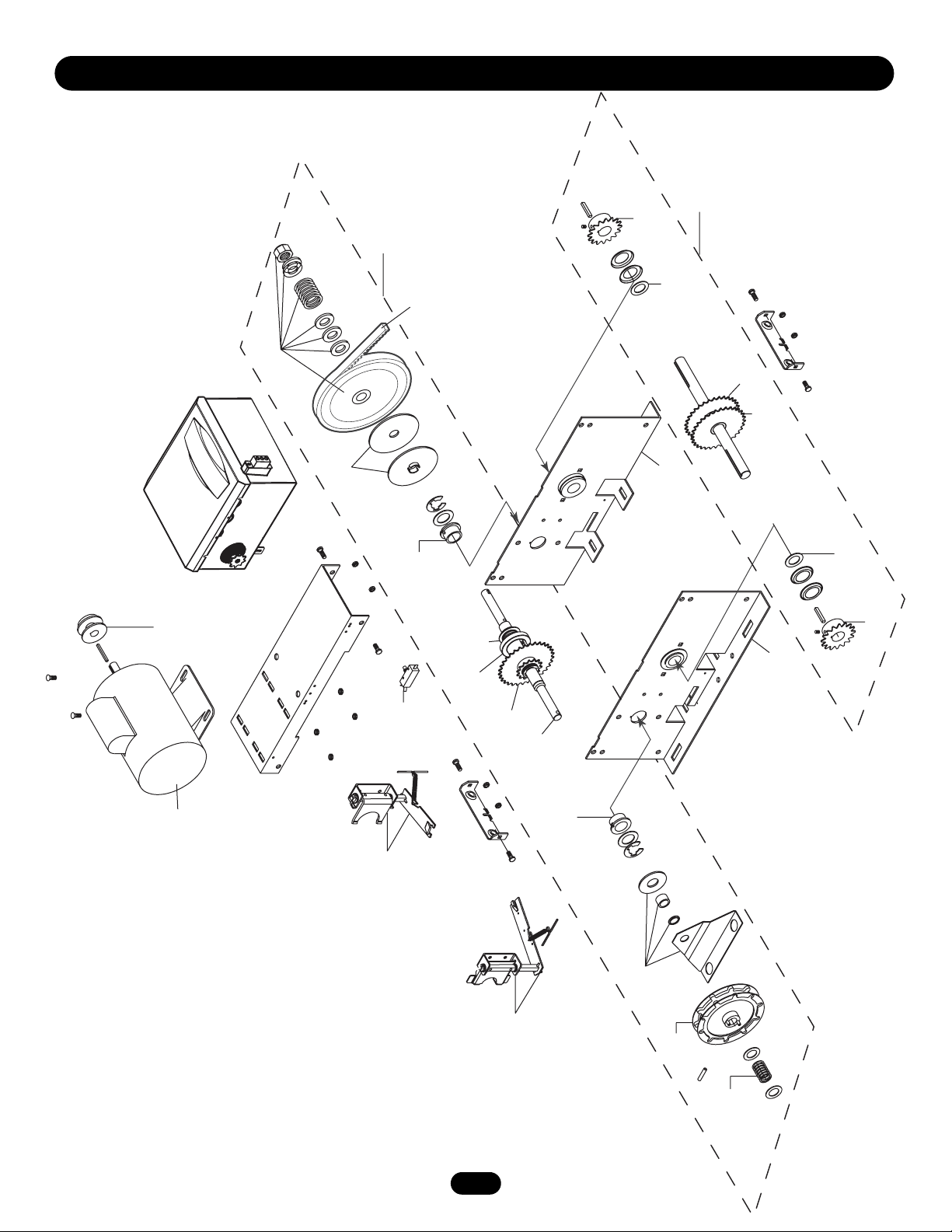
36
MODEL HJ
2
20
21
17
16
12
13
12
14
22
11
12
1
3
4
6
19
18
8
15
7
2
5
7
9
10
K1
K2
(K72-19974)
(K72-19982)
Page 37

37
REPAIR PARTS KITS - MODEL HJ
SERVICE KITS
ITEM PART # DESCRIPTION
K1 K72-19982 Clutch shaft kit
Complete with: Clutch shaft, keyed
flange bearing, dual sprocket 32/14,
splined core sprocket, e-ring,
compression spring, pulley
assembly, thick washer, thrust
bearing, retaining ring, splined hub,
washer, and roll pin.
K2 K72-19974 Output shaft kit
Complete with: Output shaft,
sprocket assembly, dual sprocket
32/14, sprocket 48B18 X 1",
sprocket 50B12 X 1", e-ring,
washer, key, set screw 5/16"-18, roll
pin, and thin walled receiver.
NOT SHOWN
71-B120H Brake kit - 115 Volt models
71-B240H Brake kit - 230-460 Volt models
71-B575H Brake kit - 575 Volt models
Complete with: Brake hub kit, brake
release lever, brake disk, spring
cup, studs, compression springs,
brake solenoid, solenoid cover,
spacers, mounting plate, pressure
plate, feather key, and conduit.
K73-HJFRAME-L HJ frame kit, left hand
K73-HJFRAME-R HJ frame kit, right hand
INDIVIDUAL PARTS
ITEM PART # DESCRIPTION
1 11-19473 Clutch shaft - HJ
2 12-19504 Keyed flange bearing 1"
3 15-19480 Dual sprocket 32/14
4 15-19484 Splined core sprocket
5 18-11379 Compression spring
6 18-30957 Compression spring
7 75-10884 Chain wheel assembly
8 75-19985 Pulley assembly
9 75-19986 Chain guide assembly
10 80-19846 Splined hub
11 15-19478 Sprocket assembly
12 15-19480 Dual sprocket 32/14
13 15-48B18LGE Sprocket 48B18 X 1"
14 15-50B12LGH Sprocket 50B12 X 1"
15 16-5L304 Cogged belt 30.4"
16 K75-19978-L Frame Kit (LH)*
17 K75-19978-R Frame Kit (RH)*
18 K75-19977 Arm kit - J
19 K75-19981 Arm kit - H
20 17-6014 Motor pulley
21 20-1033B-LP2 Motor - models HJ3311L3, 3321L3
20-3033B-4P Motor - models HJ3323L3, 3343L3
20-3033M-5 Motor - model HJ3353L3
20-1050B-2LP Motor - models HJ5011L3, 5021L3
20-3050B-4P Motor - models HJ5023L3, 5043L3
20-3050M-5 Motor - model HJ5053L3
20-1075B-2P Motor - models HJ7511L3, 7521L3
20-3075B-4P Motor - models HJ7523L3, 7543L3
20-3075M-5 Motor - model HJ7553L3
20-1100B-2LP Motor - models HJ1011L3, 1021L3
20-3100B-4P Motor - models HJ1023L3, 1043L3
20-3100M-5 Motor - model HJ1053L3
22 K74-19987 Interlock switch
NOT SHOWN
19-48047M Roller chain, #48x47 pitch
with master link
01-19457 Owner’s Manual - English
01-19457SP Owner’s Manual - Spanish
01-19457FR Owner’s Manual - French
*Non stocked item. Please allow additional delivery time.
Page 38

38
OPERATOR NOTES
Page 39

39
OPERATOR NOTES
Page 40

CONTROL CONNECTION DIAGRAM
© 2006, The Chamberlain Group, Inc.
01-19457E All Rights Reserved
n
IMPORTANT NOTES:
1. The 3-Button Control Station provided must be connected for operation.
2. If a STOP button is not used, a jumper must be placed between terminals 4 and 5.
3. When adding accessories, install them one at a time and test each one after it is added to ensure proper installation and operatio
with the Commercial Door Operator.
3 BUTTON STATION OR 3 POSITION KEYSWITCH WITH SPRING RETURN TO CENTER AND STOP BUTTON
STANDARD
7 6 4 5
10
2 OR MORE KEY LOCKOUT
7 6 4 5
10 10
7 6 4 5
(RED)
Open
Maintenance
Alert LED
(WHITE)
2 BUTTON STATION OR 3 POSITION KEYSWITCH WITH SPRING RETURN TO CENTER
7 6 4
1 BUTTON STATION OR ANY AUXILIARY DEVICE
OPEN / CLOSE
Close
Stop
STANDARD
Open
Close
1
4
B2, T, TS & FSTS
(RED)
Maintenance
Alert LED
(WHITE)
D1 & E2
MODE ONLY
See note 2.
MODE ONLY
See note 2.
Open
Close
Stop
Open
Close
Stop
7 6 4
Open
Close
LiftMaster Brand Receiver
Maintenance
Alert LED
(WHITE)
2 OR MORE
Open
Close
RADIO CONTROLS
OPEN / CLOSE
R1 R2 R3
Any Commercial Type
(RED)
Open
Close
Stop
Keyswitch
D1 & E2
MODE ONLY
See note 2.
SENSING DEVICE TO REVERSE OR STOP
Note: 11 and 4 are both the same common.
Either is acceptable.
11
8
Sensing Device
EXTERNAL INTERLOCK
Remove Factory Installed Jumper
When Interlock is Used
2
3
ONE 2 OR MORE
All Wiring Types
2
3
 Loading...