

Page 1

Installation Instructions
Hydraulic Models: HS670-100-S1
HS670-200-S1
Vehicular Slide Gate Operator
Doc 01-20228
Rev D
Page 2

2
Contents
Contents
General Information _____________________________________________ 3
Supplied Parts _____________________________________________________________ 3
Specifications _____________________________________________________________3
Dimensional Outline ________________________________________________________ 3
Safety Information_______________________________________________ 4
Safety Instructions__________________________________________________________ 4
Safety Precautions for Open-Roller Gates and Ornamental “Grill Type” Gates __________ 6
Pre-Installation Check-List ________________________________________ 8
Wiring Specifications _______________________________________________________8
Operator Features ______________________________________________ 11
Programmable Features_____________________________________________________ 13
Led Descriptions __________________________________________________________ 14
Installation____________________________________________________ 15
Step 1:
Step 2: Drive Rail ________________________________________________________ 16
Step 3:
Step 4: Vent Cap_________________________________________________________ 17
Step 5: Limit Shoes_______________________________________________________ 18
Step 6:
Step 7: Power Wire Connections ____________________________________________ 20
Step 8: Programming _____________________________________________________ 22
Step 9: Preliminary System Check Out _______________________________________ 26
Step 10: Accessory Installation_____________________________________________ 27
Concrete Pad______________________________________________________ 15
Operator Mounting_________________________________________________16
Suspension System_________________________________________________ 19
Required Maintenance___________________________________________ 28
Warranty______________________________________________________ 29
Doc 01-20228
Rev D
Page 3
General Information
Supplied Parts
General Information
3
Inspect the operator for any possible shipping
damage and any shortage of parts. Please
note that if accessories were ordered with this
unit, some may be packed separately.
! Install
Gate Warning Plates
on both sides
of the gate where they can be easily seen.
Do not
!!
run operator without vent cap
installed.
Part Description Qty.
¼ -20 Bolt 4
¼ Lockwasher 4
¼ -20 Hex Nut 4
10-24 Screw 4
10 Lockwasher 4
10-24 Hex Nut 4
Limit Shoe 2
Gate Warning Plate ! 2
Gate Safety Flyer 1
Vent Cap !! 1
Table 1
Specifications
MODEL HS670-100-S1 MODEL HS670-200-S1
Horsepower 1 H.P. 2 H.P.
Pump P.S.I. 600 1500
Gate Size & Weight Designed For Most Lengths & Weights of Slide Gates
Frequency of Use Designed for High Cycle Rates
Primary Voltages 120-230-460 1Ø & 3Ø 230-460 3Ø Only
Secondary Voltages 24 Vac/12 Vac 24 Vac/12 Vac
Table 2
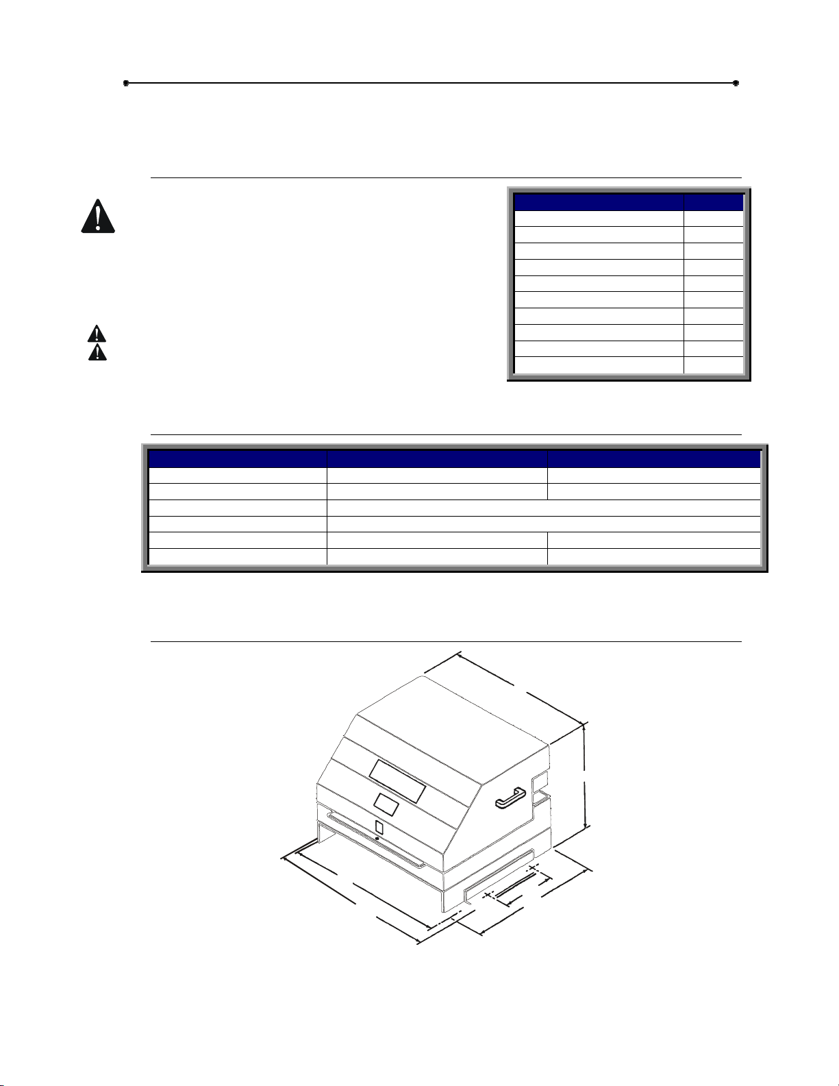
Dimensional Outline
29 3/4”
31 3/4”
27”
19 3/4”
14”
26 1/2”
01-20221F1
Figure 1
Doc 01-20228
Rev D
Page 4
4
Safety Information
Safety Information
Vehicular gate systems provide convenience and security. Gate systems are
comprised of many component parts. The gate operator is only one component. Each
gate system is specifically designed for an individual application.
Gate operating system designers, installers and users must take into account the
possible hazards associated with each individual application. Improperly designed,
installed or maintained systems can create risks for the user as well as the bystander.
Gate systems design and installation must reduce public exposure to potential hazards.
A gate operator can create high levels of force, in its function as a component part of a
gate system. Therefore, safety features must be incorporated into every design.
Specific safety features include:
Gate Edges Enclosed Track Vertical Posts
Guards for exposed
rollers
Screen Mesh
Important instructions follow. These instructions are intended to highlight certain safety
related issues. These instructions are not intended to be comprehensive. Because
each application is unique, it is the responsibility of the purchaser, designer, installer
and end user to ensure that the total gate system is safe for its intended use.
Photo-electric
Sensors
Instructional and
Precautionary Signage
Safety Instructions
Select instructions are highlighted with this precautionary symbol (see left margin).
Failure to follow these selected instructions can result in serious injury or death.
STEP 1: BEFORE INSTALLATION
1
Confirm gate operator model is specified by Installation and Maintenance
Manual for application type, gate size and frequency or use.
2
Confirm ALL appropriate safety features, such as gate edges, photo-electric
sensors, vertical posts and enclosed tracks, are specified.
3
Confirm gate system design reduces pinch points and protects against
entrapment.
4
Confirm gate system design has pedestrian access separate from vehicular
entrance.
5
6
7
8
9
10
Doc 01-20228
Rev D
Confirm gate system design reduces traffic backup.
Confirm warning signage is included in design.
Confirm gate moves freely before installation of operator
Repair or service worn or damaged gate hardware before installation of
operator.
To avoid installation hazards, review the gate system operation and
installation procedures, such as manual disconnect mechanism procedure.
Confirm control design prohibits unauthorized use.
Page 5
STEP 2: DURING INSTALLATION
1
Disconnect power at service panel before making any electrical connection.
2
Avoid pinch points, be aware of all moving parts.
3
Adjust clutch or load sensing device to minimum force setting.
4
Do not over-tighten cutch or adjust force setting above minimum.
5
Install controls where user cannot touch gate while operating controls.
6
Install controls where user has full view of gate operation.
7
Install two or more warning signs on the gate to alert persons in the area of
automatic gate operation. Warning signs must be conspicuous.
Safety Information
5
8
Install operator inside fence line.
fence line.
9
Secure gate operator cover.
STEP 3: AFTER INSTALLATION
1
Test all safety features.
2
Train end user about basic functions and safety features of gate system.
3
Leave Installation and Maintenance Manual and Safety Instructions with
end user.
Do not
install operator on public side of
Doc 01-20228
Rev D
Page 6
6
Safety Information
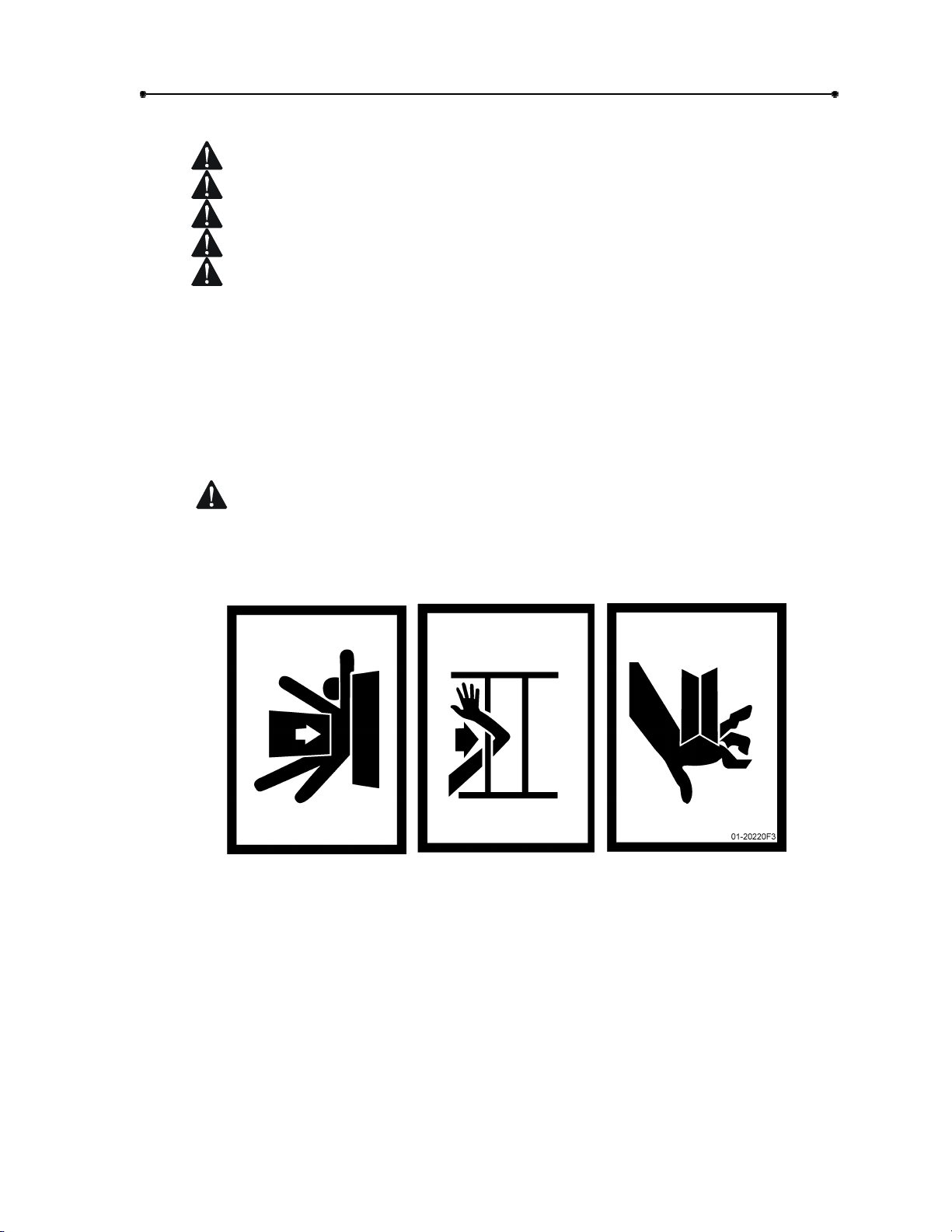
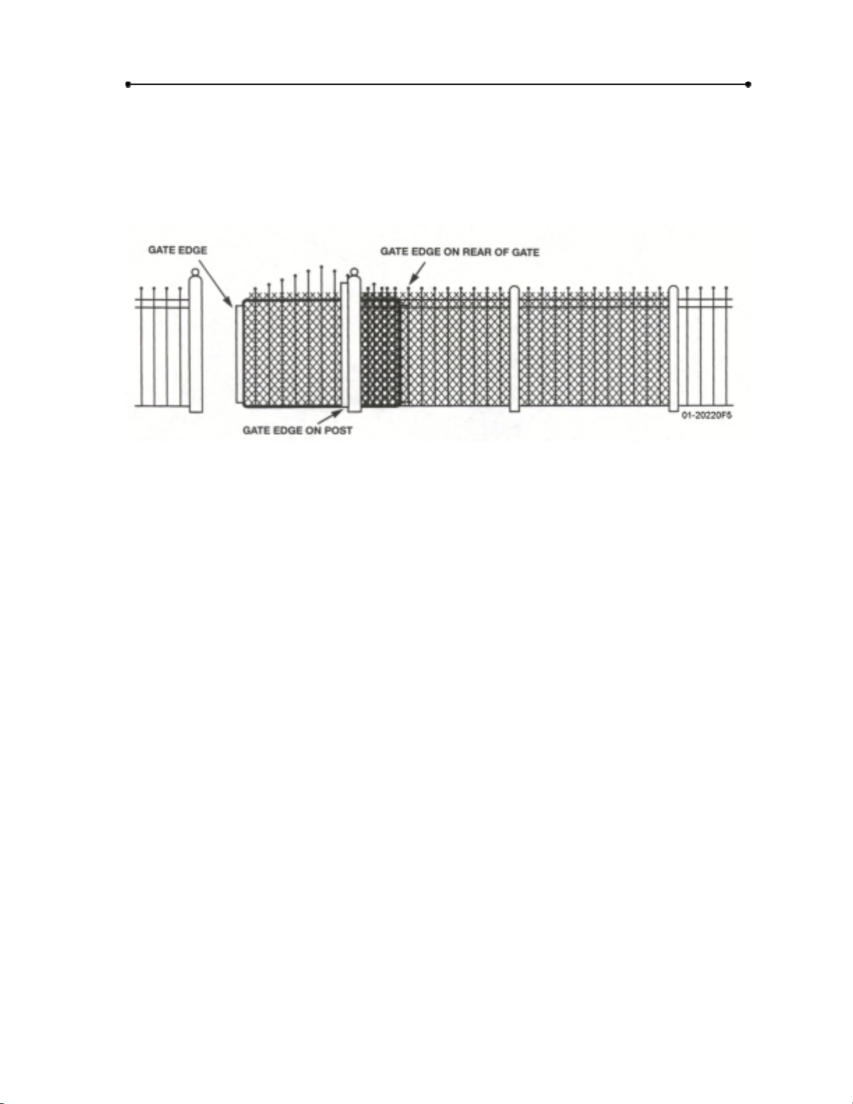
Safety Precautions for Open-Roller Gates and
Ornamental “Grill Type” Gates
OPEN-ROLLER GATES
Injuries occur when people get their or feet caught between the top or bottom of the
gate and the gate roller. This potential pinch-point should be guarded against at all
times. Enclosed style gate tracks are available for refitting of these rollers from
many fence suppliers. Also, roller guards are available for installing over the
rollers.
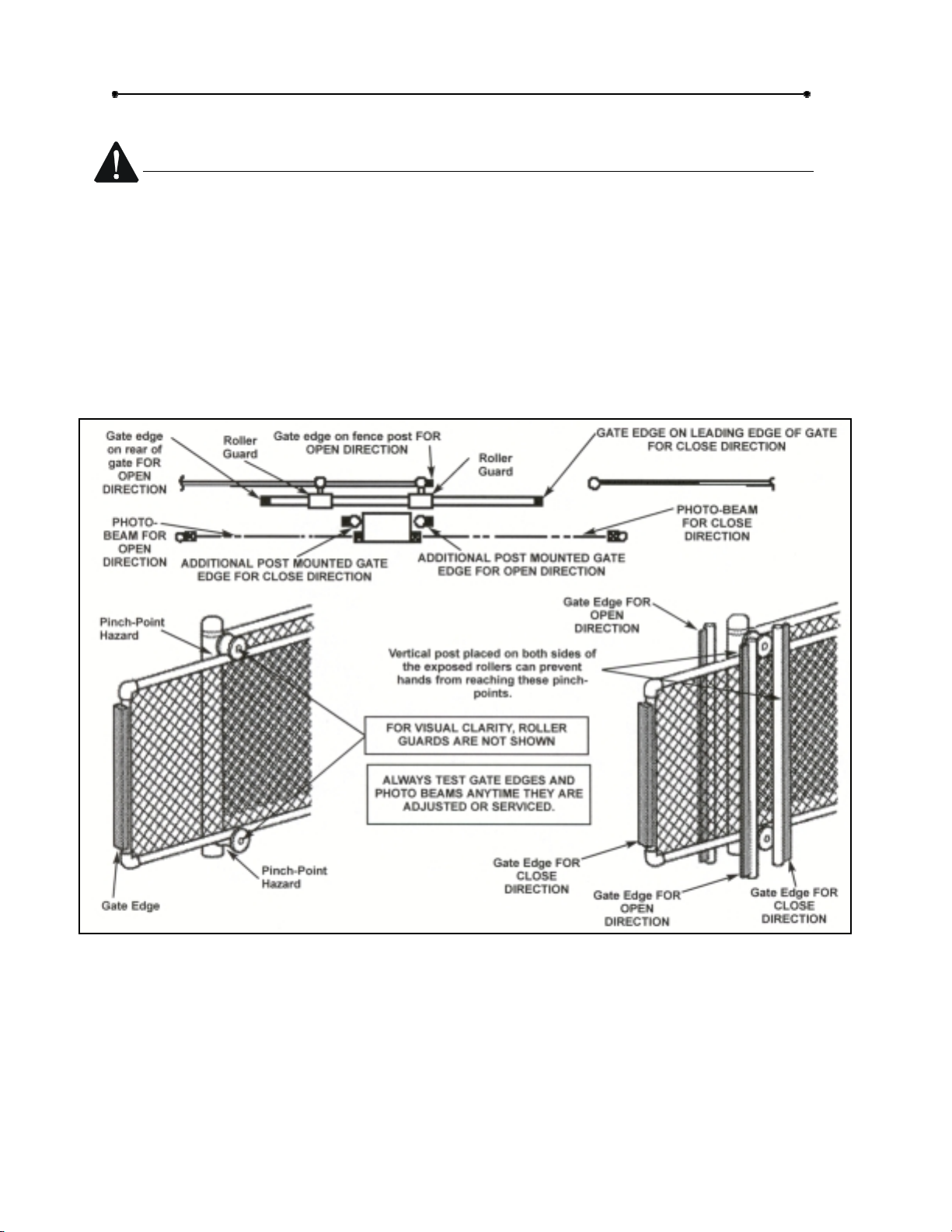
One ore more contact sensors shall be located at the leading edge, trailing edge,
and post-mounted both inside and outside of a vehicular horizontal slide gate.
Doc 01-20228
Rev D
Figure 2
Page 7
Safety Information
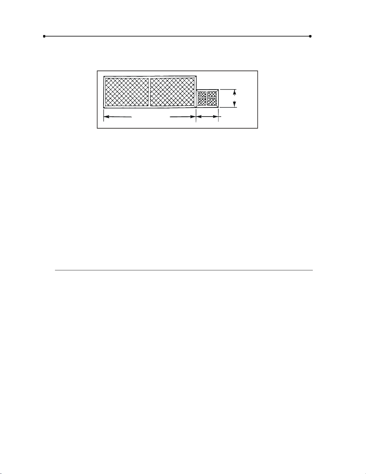
ORNAMENTAL “GRILL TYPE” GATES
Injuries occur when people put their hands and arms through openings in the grill
and the gate is operated. They cannot retract their arms and it gets caught between
the moving gate grill and the stationary fence post or fence. This potential hazard
can be averted by placing a screen mesh on the gate to prevent access through
openings anywhere the gate may travel.
Figure 3
7
Doc 01-20228
Rev D
Page 8
8
Pre-Installation Check-List
Pre-Installation Check-List
BACKFRAME
2 FT.
GATE
OPENING
Figure 4
Φ
Check the gate. It
adjust or repair the gate prior to operator installation. The gate
plumb.
Φ
Some gates may only be as wide as the gate opening. They may require a
backframe to be constructed to allow for chain attachments See Figure 4.
Φ
Double check the size and weight of the gate to make sure that this operator is
proper for this application.
Φ
If wiring has already been installed, check to make sure it meets the following
specifications and requirements.
must
operate smoothly and freely. If necessary, lubricate,
3 FT. MIN.
01-20228 F8
must
Wiring Specifications
A.
The distances shown are measured in feed from the operator to the power
source.
be level and
B.
These calculations are based on the National Electrical Code and allows for a
5% voltage drop.
C.
Supply voltage must be within 10% of the operator’s rating under load
conditions.
D.
These calculations are based on stranded copper wire.
E.
It is highly recommended that only 90% of the distances shown be used; this will
allow for a 10% safety factor.
F.
For dual units, the distance shown should be cut in half.
G.
When wire larger than 12 gauge is used, a separate junction box will be required
for operator power connections (not supplied).
H.
All local codes must be strictly adhered to.
I.
Do not run control wires in the same conduit with power wires.
J.
Do not run parallel conductor cable for controls.
Doc 01-20228
Rev D
Page 9
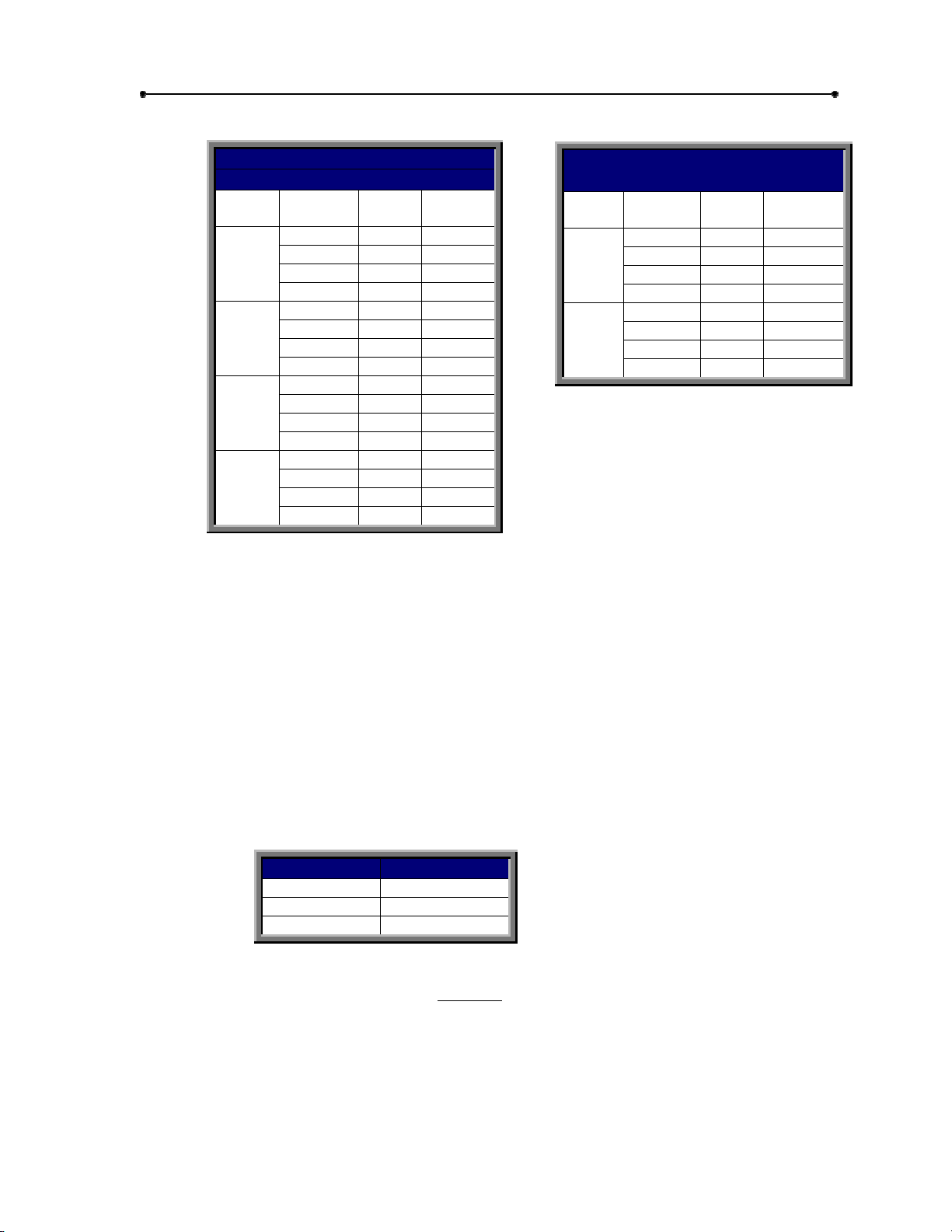
POWER WIRING
Pre-Installation Check-List
9
VOLT.
H.P.
230
1HP
460
1HP
230
2HP
460
2HP
THREE PHASE
MAX. DIST. (FT.)
SINGLE
UNIT
343 171 12
546 273 10
868 434 8
1381 690 6
1593 796 12
2533 1266 10
4029 2014 8
6407 3203 6
181 90 12
289 144 10
459 229 8
731 365 6
796 398 12
1266 633 10
2014 1007 8
3203 1601 6
DUAL
Table 3
UNIT
WIRE
GAUGE
VOLT
H.P.
115
HP
230
1HP
SINGLE PHASE
MAX. DIST. (FT.)
SINGLE
UNIT
56 28 12
89 44 10
143 71 8
227 113 6
226 113 12
359 113 10
572 179 8
909 286 6
DUAL
UNIT
WIRE
GAUGE
CONTROL WIRING
DIST./FT. WIRE GAUGE
800 18
1200 16
2000 14
Table 5
FORMULA L = (V) x (D)
L = Max. one way dist.
V = Voltage Drop (5%)
D = Cross Section area of conductor (cir.mil.)
Table 4
(2K) x (I)
Doc 01-20228
Rev D
Page 10

10
Pre-Installation Check-List
K= Resistivity of conductor (24)
I = Motor F.L.A. (NEMA suggested)
WIRE GAUGE DIAMETER OHMS/1000FT.
16 1/20” 4 Ω
14 1/16” 2.5 Ω
12 1/12” 1.6 Ω
10 1/10” 1Ω
81/8”.6 Ω
Table 6
Doc 01-20228
Rev D
Page 11

Operator Features
E
D
FG H
Operator Features
I
11
C
B
A
J
A. MOTOR 1 AND 2 H.P.
The motors used in the HS670-100 and
HS670-200 are T.E.F.C. (totally enclosed,
fan cooled) 3450 R.P.M. They incorporate
a built-in manual reset thermal overload.
B. DIRECTIONAL VALVE
3 position, 4 way. It incorporates 2
solenoids which are 24 Vdc. Rectified
from 24 Vac.
C. BYPASS VALVE
Incorporates a handle at side of pump.
When positioned downward, it will allow
manual operation of the gate.
D. VENT CAP
When removed, you may add ATF
Transmission fluid.
Must
be on during
operator operation.
E. LIMIT SWITCH
Oilitight and watertight. Nema 3, 4, & 13
construction. Open switch for right hand,
close switch for left hand.
Figure 5
0
1
2
2
-
F
0
8
2
1
F. DRIVE WHEELS
Polyurethane material on a steel or
aluminum hub. HS670-100 = 1 – ½”
wide 6” dia. HS670-200 = 2” wide 6”
dia.
G. HYDRAULIC MOTOR
Roller vane, free wheeling type with a
displacement of 12 in./3.
H. SUSPENSION SYSTEM
Incorporates two compression
springs. See also page 19.
I. LIMIT SWITCH
Close switch for right hand and open
switch for left hand.
J. RELIEF VALVE
Built into pump. Set at 600 p.s.i. for
HS670-100 and 1500 p.s.i. for
HS670-200.
Doc 01-20228
Rev D
Page 12

12
Operator Features
DIGITAL MICROPROCESSOR DISPLAY CONTROL BOARD
This is the main circuit board for the gate system (see Figure 5). It contains all the
logic and intelligence for the system. It is isolated from voltage spikes and surges
by the isolation interface board and also by an isolation transformer. This board
contains all the LED’s and the programming buttons and display.
ISOLATION INTERFACE BOARD
This circuit board (see Figure 5) protects the digital mircoprocessor display control
board. All the inputs and outputs go thorough this board. This board contains all
the relays that send and receive signals that are processed by the digital control
board.
DIGITAL MICROPROCESSOR
DISPLAY CONTROL BOARD
“UNDERNEATH
”
ISOLATION INTERFACE
BOARD “ON TOP”
01-20228F2
Figure 5
MAXIMUM RUN SHUT OFF CIRCUIT
This is a self learning circuit. It will take the average amount of time between the
opening cycle and the closing cycle and add 10 seconds to it. If this time should be
reached during operation, then this circuit will shut off the operator.
REVERSAL DELAY CIRCUIT
Built in sounder will activate four seconds prior to and during gate movement.
Sound level is adjustable. Four second delay is programmable.
NOTE:
The four second delay is programmable. See program
information.
MID OPEN CIRCUIT
When a control device is wired into this circuit, it will open the gate to a position
slightly greater than ½ way from the full closed position or if gate is less than ½ way
open. If gate should be more than ½ way open, then the control device will open
the gate to the full open position. If the time delay to close is enabled, the operator
will automatically close from the “mid-open” position.
VEHICLE REVERSE CIRCUIT
If this circuit is energized while gate is closing, gate will stop and reverse to full
open position. If energized while gate is at the full open or stopped between limits,
it will not allow the gate to be closed.
Doc 01-20228
Rev D
Page 13

Operator Features
VEHICAL OPEN CIRCUIT
A device connected to this circuit will only open the gate. If gate is closing, it will
cause the gate to stop and reverse to the full open position.
EXTERNAL WARNING CIRCUITS
Many different types of signaling systems can be connected to the operator to act
as external warnings. See the electrical diagram supplied with operator for more
information.
THREE BUTTON CONTROL CIRCUIT
Sequence of operation is, open/stop/close. Stop will override all other functions. If
closing, open will cause operator to stop and reverse to full open. If opening, close
will cause operator to stop and reverse to full close position.
ONE BUTTON CONTROL CIRCUIT
Sequence of operation – open, stop, close, stop. If power has been interrupted, will
always open with first activation.
Programmable Features
13
PROGRAM 1 (R.H./L.H.)
Will automatically set up motor rotation, limit switch functions and directional logic
for the operator.
PROGRAM 2 (MASTER/SLAVE)
Will set up two (2) operators to act as one, using common controls.
PROGRAM 3 (4 SECOND DELAY)
This program will allow you to enable or disable the 4 sec. delay before the gate
begins its open or close direction. See the Warning on page 14.
PROGRAM 4 (OBSTRUCTION SENSING CLOSE)
Will determine the response the operator will make when the gate meets an
obstruction while closing.
PROGRAM 5 ( OBSTRUCTION SENSING OPEN)
Will determine the response the operator will make when the gate meets an
obstruction while opening.
PROGRAM 6 (EXTERNAL REVERSE DEVICE)
Will program the system to accept either a normally open or normally closed
contact type external obstruction sensing device.
PROGRAM 7 & 8 (TIME DELAY TO CLOSE)
These two independent programs will allow the gate to automatically close from the
full open or mid open position after a programmed amount of time.
PROGRAM 9 (GATE LOCK)
This program will allow the use of different types of gate locks to be used with the
system.
Doc 01-20228
Rev D
Page 14

14
Operator Features
Led Descriptions
Color Name Description
Green Program
Red External Reverse
Red Maximum Run
Red N/A
Red Right Hand/Left Hand
Red Gate Closing
Red Gate Opening
Red Power
“ON” when in program mode, “OFF” when in
operational mode.
“ON” when an external reverse device was
activate, “OFF” with next input.
“ON” when maximum run circuit shut operator off,
“OFF” with next input.
“ON” when operator is programmed R.H., “OFF”
when operator is programmed L.H., “BLINKS”
when operator has not been programmed for
either.
“ON” anytime sounder is activated prior to and
during closing.
“ON” anytime sounder is activated prior to and
during opening.
“ON” when operator electric power is on. “OFF”
when the operator has no power. “BLINKS”
when the control voltage of the operator drops
below 18 VAC, or if power was lost then restored.
Table 7
NOTES: Program 2 (Master/Slave)
If for some reason both operators must be handed the same (both R.H.
or L.H.). Then both operators must be programmed as SLAVES. All
controls will be connected to either operator. You will still need the
three (3) wire interconnect between the two operators.
Please be aware that these operators are transmitting data through the
master/slave interconnection. It is very similar to a RS232 connection.
very important
It is
power wires and positioned far away from power lines or conduits. If
the mater/slave interconnection receives any type of voltage
interference or noise, neither of the two operators will function properly.
that these three wires be shielded from any and all
WARNING
very important
It is
The only situations where the delay would be disabled is for extreme security
installations where the need for the gate to immediately open or close is required.
IMPORTANT NOTE:
was reversed to open by either of the external obstruction circuits, (ref. adaptions
6 & 7 on wiring diagram). The operator will require a manual signal to close the
gate. The time delay to close will function normally after the manual signal.
that the four second delay be enabled for most applications.
The time delay to close feature will NOT activate if the gate
Doc 01-20228
Rev D
Page 15

Installation
INSTALLATION NOTES
Installation
15
Installation shown is for a right-
handed unit (on right side of gate
opening when inside looking out).
Left-handed is opposite.
Step 1:
Concrete Pad
1
Layout concrete pad as detailed.
2
Locate conduit, as required, prior to pouring concrete.
3
Pour concrete, insuring that pad is level and above the ground line. Pad must
be a minimum of 24 inches in depth or below the frost line, whichever is
greater.
4
Allow concrete to set at lease 2 days before installing unit.
5
Locate four (4) ½” threaded anchors (not supplied) or other means of fastening
as shown. Anchors must be positioned accurately and be secure in the
concrete.
NOTES
Always use separate conduits for
power wiring and control wiring.
For detailed information on the
emergency disconnect system,
see instructions supplied with it.
If there is existing concrete at area of unit
mounting, use dimensioning procedure
described in step 1. You may need to modify
any conduit locations to suit your application.
This is only a suggested
layout, other pad layouts are
possible.
You may want to install extra
conduit for future wiring
considerations.
“GATE”
SHOWN
OPEN
AS
REQ’D.
5 7/8
0
1
2
-
2 3/4”
0
2
2
ANCHOR LOCATION
MARKED “Z”
Z
OPTIONAL EMERGENCY
DISCONNECT
Z
CONDUIT
1
F
6
29 3/4”
35”
3”
X
X
X
X
+ 7 1/2”
Z
26 1/2”
14”
Z
3 7/8”
3 3/4”
2 5/8”
X = 1 3/4”
+ = CRITICAL DIMENSION
Figure 7
Doc 01-20228
Rev D
Page 16

16
Installation
Step 2:
Important:
Step 3: Operator Mounting
Drive Rail
The drive should be:
Level and parallel to the gate and
operator.
As close as possible to the 11-1/2”
dimension.
Very securely mounted to the gate
and backframe.
The length of the drive rail should
be the gate opening width plus 2
to 3 feet.
1
Remove the outer cover from the operator.
2
Carefully secure the concrete pad with the drive wheels facing the gate.
IMPORTANT NOTE:
and drive rail. By loosening the bolts securing the mounting logs to the
unit, the operator can be slightly adjusted up or down. Retighten bolts.
The operator
Figure 6
must
be lever the parallel with the gate
01-20228F3
CAUTION
Make sure that the drive rail and wheels are aligned properly (see Figure
8).
01-20228F4
Figure 7
Doc 01-20228
Rev D
Page 17

Installation
17
Step 4:
Remove the threaded plug from the pump tank and install the vent cap in its place.
Vent Cap
IMPORTANT NOTE
Never run the operator without the vent cap in place.
Figure 8
01-202 21F8
Doc 01-20228
Rev D
Page 18

18
Installation
Step 5:
1
2
3
4
5
Limit Shoes
Manually open the gate to the full open position.
Locate the open limit switch lever and mark its position on the drive rail.
Manually close the gate to the full close position.
Locate the close limit switch lever and mark its position on the drive rail.
Manually open the gate about halfway. Per drawings below, measure and drill
holes. Mount both limit shoes to underside of drive rail.
IMPORTANT NOTES
The limit shoes are slotted, so minor adjustments may be made later for
fine tuning of the full open and close positions. Also, note that the limit
switches themselves may be slightly adjusted up or down.
It is highly suggested that gate stops be installed to the gate at the full
open and closed positions.
Due to the fact that this unit has no brake, there will be some gate coasting
and, depending on gate weight, it could be considerable, so it might drift
past the limits.
MARK CENTERLINE
MARK CENTERLINE
1-1/16”
LIMIT SWITC H
2”
3”
LIMIT SHOE
CENTERLINE MARKS
1/4”-20 SCR.
WASHER & NUT
Figure 11
DRIVE RAIL
9/32” DIA.
HOLES
LIMIT SWITC H
2”
01-20221F9
3”
BOTTOM OF
DRIVE RAIL
Doc 01-20228
Rev D
Page 19

Installation
19
Step 6:
The suspension system is semi-factory set; simply loosen the suspension separator bolt
completely. This will allow both wheels to pinch the drive rail.
If more or less pressure is required, adjust both upper and lower suspension spring lock
nuts as desired.
Suspension System
NOTE:
it is not removed, make sure that it can not interfere with suspension system.
IMPORTANT NOTES
It is suggested that the separator bolt be removed and left with unit. If
Both springs should apply about the same amount of pressure.
If using the LiftMaster drive rail, make sure that the drive rail guide
wheel is positioned properly. See Figure 9.
Important
pressure on the drive wheels so they can pinch together on the drive
rail. This system also allows the drive wheels to “float” so the can
follow any slight misalignment of the drive rail. If the springs are over
tightened, it will reduce their life span. But, on the other hand, if they
are under tightened, the drive wheels may slip on the drive rail.
: Adjust the suspension system properly. This system puts
Figure 9
01-20221F10
Doc 01-20228
Rev D
Page 20

20
Installation
Step 7:
Power Wire Connections
CAUTION
Make sure power is disconnected at main power supply and at power disconnect
switch on the unit before proceeding.
1
Secure all electrical power connections to the power wiring terminal strip.
Single phase to L1, L2 and GROUND. Three phase to L1, L2, L3 and
GROUND.
2
Connect all controls to the control wiring terminal strip. Refer to the electrical
diagram supplied with the unit.
IMPORTANT NOTE:
can her the pump running by the gate does not move:
Make sure the manual bypass valve is in the automatic operation
position.
If the bypass valve is OK, disconnect the main power supply and
reverse any two wire connections at the power terminal strip.
POWER DISCONNECT
On three-phase units, when unit is first run, if you
SWITCH
Doc 01-20228
Rev D
GROUND
01-20228F5
POWER TERMINAL
STRIP
Figure 10
Do not operator until instructed! Operator must be
programmed before operation.
Page 21

Installation
21
MANUAL OPERATION
The pump is equipped with a manual bypass valve. By positioning the valve
handle down (manual operation), the gate can be back-driven open or closed.
A back-up to this is the suspension separator bolt. By tightening this bolt, the drive
wheels will be pushed off by the drive rail.
NOTE:
When manually opening or closing the gate, it is not, in the
beginning, easy to get the gate started. Since fluid has accumulated in the
drive motors, it will take a good size push to get the gate started.
01-20221 F11
Figure 13
FACTORY INSTALLED ACCESSORIES
Most factory-installed accessories are located on or under the control panel and are
already wired into it.
NOTE:
way.
By removing one bolt, the entire control panel can be pivoted out of the
Figure 14
Doc 01-20228
Rev D
Page 22

22
Installation
Step 8:
Programming
This gate controller has (9) programmable options which must be set prior to gate
operation. To program the controller, press and hold the “FUNCTION” select push
button for 2 seconds. When the board enters the program mode, the green program
LED will turn on and the two display panels will become active.
When the controller enters the program mode and the program LED turns on, the
“FUNCTION” display panel will display “0” (zero) and the “OPTION” display panel will
display “0” (zero).
To exit the program mode, at any time, press and hold the “FUNCTION” select push
button for 2 seconds. The program LED will turn off, indicating that you are out of the
program mode. The board will reset as if first powered on.
PROGRAM
EXT. REVERSE
MAX. RUN
OBSTRUCTION
RIGHT HAND
CLOSING
OPENING
POWER
Figure 11
01-20228F6
Doc 01-20228
Rev D
Page 23

Installation
23
PROGRAM 1:RIGHT HAND/LEFT HAND OPERATION
0 = NOT SELECTED - OPERATOR WILL NOT FUNCTION IN THIS MODE.
1 = RIGHT HANDED - OPERATOR WILL MOVE GATE FROM LEFT TO
RIGHT TO OPEN.
2 = LEFT HANDED - OPERATOR WILL MOVE GATE FROM RIGHT TO LEFT
TO OPEN.
Program 1 determines whether the operator is “right handed” or “left handed”. To
determine which type your gate controlled needs to be set to, observe the
installation from the operator side of the gate. If the operator is on the right side of
the gate. If the operator is on the right side of the opening, the operator is “right
handed”. If the operator is on the left side of the opening, it is “left handed”.
Press the FUNCTION select button to set the function to “1”. The option display
will show a “0”, “1” or “2”. Option “0” is the factory setting and does not allow gate
movement. This option must be changed to either a “1” for right hand or “2” for left
hand. Pressing the “OPTION” button will change the option between “1” and “2”.
When the correct option for your application is indicated, press the “FUNCTION”
select button to save this selected option and to step to the next program.
PROGRAM 2:MASTER/SLAVE OPERATION
0 = SINGLE GATE OPERATOR INSTALLATION.
1 = MASTER GATE OPERATOR – PROGRAMS THE SLAVE AT POWER
UP.
2 = SLAVE GATE OPERATOR – PROGRAMMED BY THE MASTER AT
POWER UP.
Program 2 selects whether the installation is a single operator or dual operators
with common controls.
If the “FUNCTION” display shows “2”, proceed on as follows. If it does not show “2”
then press the “FUNCTION” select button to set the display to “2”. The “OPTION”
display will indicate a “0”, “1” or “2”. The “0” option is the factory setting and is for
single operation gates. This option can be changed to “1” or “2” for dual gate
operators. Pressing the “OPTION” select button will change the option between
“0”, “1” or “2”, where option “1” is for master operation and “2” is for slave operation.
A master operator will automatically program its slave when it is powered up and
when the program mode is ended. The master will automatically set the slave up
as a slave. If the master was programmed for right hand, the slave will be set for
left hand and visa versa. All other programmed options (i.e. time delay to close,
reversal options, etc.), will be copied directly from the master to the slave. When
the correct option for your application is indicated, press the “FUNCTION” select
button to save this selected option and to step to the next program.
IMPORTANT NOTE:
interconnection wires in place between the two operators for the master/slave
system to work. Reference the wiring diagram supplied with units.
The two operators (master/slave) must have the 3
Doc 01-20228
Rev D
Page 24

24
Installation
PROGRAM 3:FOUR SECOND PRE-OPERATION DELAY
0 = FOUR SECOND DELAY “OFF”.
1 = FOUR SECOND DELAY “ON”.
Program 3 selects whether or not there will be a four (4) second delay prior to gate
movement. During the delay, the sounder will beep.
If the “FUNCTION” display shows “3”, proceed on as follows. If it does not show “3”
then press the “FUNCTION” select button to set the display to “3”. The “OPTION”
will indicate a “0” or “1”. The “1” option is the factory setting. By pressing the
“OPTION” select button you can change this setting to “0”.
WARNING
Unless the job site is an extremely high security installation, program 3
should always be set to “ON”.
PROGRAM 4:REVERSE WHEN CLOSING
0 = REVERSE FOR 2 SECONDS THEN STOP
1 = REVERSE TO FULL OPEN POSITION
Program 4 determines the response of the gate operator to an obstruction from the
external obstruction signal while closing.
With “FUNCTION” display showing “4”, press the “OPTION” select button to select
either “0” or “1”. The factory setting is “1”.
PROGRAM 5:REVERSE WHEN OPENING
0 = REVERSE FOR 2 SECONDS THEN STOP.
1 = STOP
Program 5 determines the response of the gate operator to an obstruction from the
external obstruction circuit, (#6 on wiring diagram), while opening.
With “FUNCTION” display showing “5”, press the “OPTION” select button to choose
either “0” or “1”. The factory setting is “1”.
IMPORTANT NOTE:
device (adaption #6 on wiring diagram). Adaption #5, shown on wiring
diagram (vehicle reverse device), will always stop and reverse a closing
gate to the full open position. Adaption #7, will only react in the closing
direction.
Programs 4 & 5 are only for the external obstruction
Doc 01-20228
Rev D
Page 25

Installation
25
PROGRAM 6:EXTERNAL REVERSE DEVICE SELECT
0 = External reverse device with normally closed contacts.
1 = External reverse device with normally open contacts.
This program determines which polarity of signal on the external obstruction device
will cause the gate operator to react. If a device with normally open contacts is
used, then this option should be set to “1”. If the device has normally closed
contacts then this option should be set to “0”. The factory setting is “1”.
When the correct option is displayed, press the “FUNCTION” select button to save
the choice and to step to the next program.
PROGRAM 7:TIME DELAY TO CLOSE ENABLE/DISABLE
0 = Time delay to close “OFF”.
1 = Time delay to close “ON”.
This program enables or disables the automatic time delay to close option.
When the correct option is displayed, press the “FUNCTION” select button to save
the choice and to step to the next program.
NOTE:
program 8. By pressing the “FUNCTION” select button twice you will go to
program 9.
If timer to close option is et to disable, you will not need to do
PROGRAM 8:TIME DELAY TO CLOSE “TIME”
0 = 2 SECONDS
1 = 15 SECONDS
2 = 30 SECONDS
3 = 60 SECONDS (1 MINUTE)
4 = 90 SECONDS (1-1/2 MINUTES)
5 = 120 SECONDS (2 MINUTES)
6 = 180 SECONDS (3 MINUTES)
7 = 240 SECONDS (4 MINUTES)
This program sets the time from when the gate is fully open to the time when its will
automatically begin to close.
By pressing the “OPTION” select button, choose the time that will be required for
this gate application. Once the selection has been made, press the “FUNCTION”
select button to save this selection and to step to the next program.
Doc 01-20228
Rev D
Page 26

26
Installation
PROGRAM 9:GATE LOCK TYPE SELECT
0 = LOCK OUTPUT NORMALLY “OFF”.
1 = LOCK OUTPUT NORMALLY “ON”.
If a gate lock is to be used with the operator, this program determines the state of
the built-in lock relay contacts and how they will turn on an off.
By pressing the “OPTION” select button, choose either option “0” or “1”. Option “0”
would normally be selected if you are using a solenoid activated type lock system.
The built-in lock relay’s contacts will be open when gate is closed. They will close
for one second before the gate begins to open, and open up tow seconds after the
gate has begun moving. Option “1” would normally be selected if you are using a
magnetic type lock system. The built-in lock relay’s contacts will be closed while
the gate is closed. They will open up one second before the gate begins to open
and remain open. With either selection the contacts will be closed when the gate
begins to close.
NOTE:
operator. If no lock system is to be used, it does not matter which option
is shown in the display.
This was the last programming option. To exit program mode, press and hold the
“FUNCTION” select button for 2 seconds. The green program LED will turn off.
You may not proceed to step 8.
IMPORTANT NOTE:
open and to the full closed positions), before the maximum run timer and
the R.P.M. sensor will function. They both must learn their proper
settings. Also, anytime the operator is reprogrammed it MUST be run one
complete cycle.
Step 9:
Before adding any options, accessories or adaptions, it is highly recommended that you
check out the system and its programs. If you have not already done so, temporarily
connect a 3 button station to the control terminal strip, see below or see wiring diagram
supplied with operator. Test for proper open, stop and closing of the gate. Test for
proper operation of all programs that were programmed into the system. Once
everything checks out okay, then proceed to adding on the accessory items for this job
site.
Preliminary System Check Out
For wiring information see electrical diagram supplied with
The operator MUST be run one full cycle, (to the full
Doc 01-20228
Rev D
NOTE:
each one is attached check it for proper operation before adding the next.
We recommend that, if more than one accessory item is used, after
Page 27

Installation
27
Step 10:
Accessory Installation
See page 8 for wiring distance and wire gauge information.
See wiring diagram for more information.
Important:
Make sure that the two (2) gate caution signs are secured to the gate: one
on the inside and one on the outside. They must be easily visible.
WARNING
If exterior controls such as keyswitch, card reader or pushbutton station are to
be incorporated into this system, make sure the controls are installed where
the user cannot touch the gate while operating controls. Install the controls
where the used had full view of gate operation.
NOTES
0
1
-
2
0
2
2
8
F
7
Figure 12
Both item 6 & 7 can be programmed for the close direction, reference
program #4.
Only item 6 can be programmed for the open direction, reference program
#5.
Item 7 is for use with photo-beam type systems. Item 6 is for use with gate
edge type systems.
Doc 01-20228
Rev D
Page 28

28
Installation
Required Maintenance
Normal Usage
ITEM
External safety
systems
Gate caution signs
Manual operation
Gate
Accessories
Electrical
Frame bolts Check for tightness
Total unit
Fluid levels (D) Keep at least ¾ full
Fittings Check for leaks
Drive rail Check for damage
Drive wheels Check for wear
MAINTENANCE
Month3Months6Months12Months
Check for proper operation
Make sure they are
present
Check & operate by-pass
valve
Inspect for wear or
damage
Check all for proper
operation
Inspect all wire
connections
Inspect for wear or
damage
Check at least once every
1
√
√
√
COMPLETE CHECK
√
√
√
√
√
√
√
√
NOTES:
Doc 01-20228
Rev D
Table 8
When servicing, always disconnect operator from electrical power supply.
Severe or high cycle usage will require more frequent maintenance checks.
Inspection and service should be preformed anytime a malfunction is
observed or suspected.
Use only “ATF” automatic transmission fluid. If using the optional cold
weather fluid (Royco 756) only replace with the same.
When servicing, please do some “house cleaning” of the operator and the
area around the operator. Pick up any debris in the area. Clean the
operator if needed.
Page 29

Warranty
LIMITED ONE-YEAR WARRANTY
LiftMaster gate operators are warranted against deficiencies in material and
workmanship for a period of one (1) year from date of purchase, providing
recommended installation and maintenance procedures are followed. This
warranty is in lieu of all other warranties expressed or implied (some states do not
allow limitations on how long an implied warranty lasts, so this limitation may not
apply to you) and shall be considered void if damage was caused by fire, flood or
lightening. The manufacturer will not be responsible for any labor charges incurred
in the removal or replacement of deficient parts.
In case of failure due to deficiencies in material or workmanship during the warranty
period, the complete gate operator will be repaired or replaced items in warranty.
Required Maintenance
29
Doc 01-20228
Rev D
Page 30

COPYRIGHT 2001
ALL RIGHTS RESERVED
This document is protected by copyright and may not be copied or adapted without the prior written
consent of LiftMaster. This documentation contains information proprietary to LiftMaster and such
information may not be distributed without the prior written consent of LiftMaster. The software and
firmware included in the LiftMaster product as they relate to this documentation are also protected by
copyright and contain information proprietary to LiftMaster.
FOR TECHNICAL SUPPORT
Call our toll free numbers:
(800) 323-2276
(800) 998-9197
Installation and service information is
available six days a week.
TO ORDER REPAIR PARTS
Call our toll free numbers:
(800) 528-2806
(800) 998-9197
Prepare to provide the following
information when ordering repair parts:
Part Number
"
Part Name
"
Model Number
"
 Loading...