

Page 1
Installation Instructions
Commercial Vehicular
Slide Gate Operator
Hydraulic Models: HS670-100-B2
HS670-200-B2
Doc 01-20221
Rev D
Page 2

2
IMPORTANT!
Installers: Leave this manual with the end user after completing the installation.
Limited One-Year Warranty
LiftMaster gate operators are warranted against deficiencies in material and
workmanship for a period of one (1) year from date of purchase, providing
recommended installation and maintenance procedures are followed. This warranty is
in lieu of all other warranties expressed or implied (some states do not allow limitations
on how long an implied warranty lasts, so this limitation may not apply to you) and shall
be considered void if damage was caused by fire, flood or lightening. The manufacturer
will not be responsible for any labor charges incurred in the removal or replacement of
deficient parts.
In case of failure due to deficiencies in material or workmanship during the warranty
period, the complete gate operator will be repaired or replaced items in warranty. For
information on how to obtain replacement parts or a replacement operator under terms
of this warranty, contact LiftMaster.
Doc 01-20221
Rev D
Page 3

Contents
Contents
General Information_____________________________________________4
Inspection ______________________________________________________________ 4
Specifications ___________________________________________________________ 4
Operator Information______________________________________________________ 5
Safety Information ______________________________________________6
Safety Instructions________________________________________________________ 6
Safety Precautions for Open-Roller Gates and Ornamental “Grill Type” Gates ________ 8
Pre-Installed Check List_________________________________________10
Wiring Specifications ____________________________________________________ 10
Installation ___________________________________________________13
Installation Notes________________________________________________________ 13
3
Step 1:
Step 2: Drive Rail ______________________________________________________ 15
Step 3:
Step 4: Vent Cap_______________________________________________________ 16
Step 5: Limit Shoes_____________________________________________________ 17
Step 6:
Step 7: Manual Operation________________________________________________ 21
Step 8: Factory Installed Accessories_______________________________________ 22
Step 9: Electrical Wiring_________________________________________________ 23
Step 10: Reversing Device ________________________________________________ 23
Concrete Pad____________________________________________________ 13
Mounting ______________________________________________________ 16
Suspension System_______________________________________________ 19
Left Hand/Right Hand Conversion ________________________________24
Operator Check-Out ____________________________________________25
And Finally… _________________________________________________26
Required Maintenance Services ____________________________________________ 26
Doc 01-20221
Rev D
Page 4
4
General Information
General Information
Inspection
Inspect the operator carefully for any possible shipping damage. Using the packing list
supplied with the unit as a guide, check for any shortage of parts.
IMPORTANT NOTE
Do not run operator without vent cap installed. For more detailed information
about electrical, hydraulic and mechanical systems, see the troubleshooting guide
supplied with the unit.
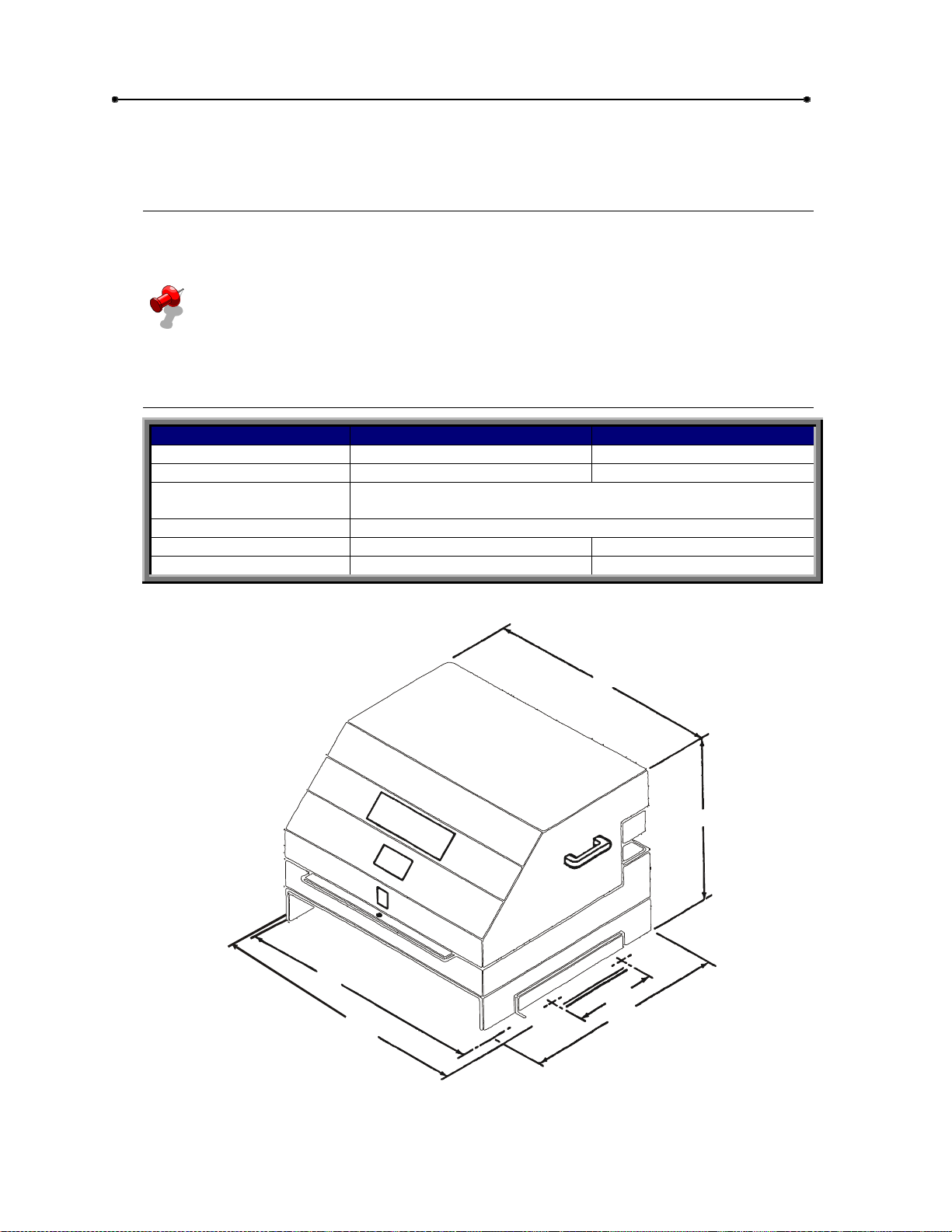
Specifications
MODEL HS670-100 MODEL HS670-200
H.P. 1 2
GATE SPEED 15 TO 18”/SEC. 15 TO 18”/SEC.
MAX. GATE SIZE DESIGNED FOR MOST LENGTHS AND WEIGHTS OF SLIDE
GATES
FREQUENCY OF USE DESIGNED FOR VERY HIGH RATES
PRIMARY VOLTAGES 120-230-460 120-230-460
SECONDARY VOLTAGE 24 VAC. 24 VAC.
29 3/4”
31 3/4”
Table 1
27”
19 3/4”
14”
26 1/2”
01-20221F1
Doc 01-20221
Rev D
Figure 1
Page 5

General Information
Operator Information
A. A.C. MOTOR-HS670-100 = 1 H.P./3450 R.P.M. HS690-200 = 2 H.P./3450
R.P.M. Both have continuous duty rating. And built-in manual reset overload.
B. DIRECTIONAL VALVE – 2 position, 4 way 24 vac.
C. BYPASS VALVE – For manual operation.
D. VENT CAP – When removed, add fluid here.
E. LIMIT SW ITCH – is open switch for R.H. and close switch for L.H.
F. DRIVE WHEELS – HS670-100 = 1 ½” x 6”. HS670-200 = 2” x 6”.
G. HYDRAULIC MOTOR – Roller Vane Type. Displacement = 12 in./3.
H. SUSPENSION SYSTEM – See instructions.
I. LIMIT SWITCH – is close switch for R.H. and open switch for L.H.
J. RELIEF VALVE – Built into pump.
K. CONTROL PANEL
5
Figure 2
01-20221F2
Doc 01-20221
Rev D
Page 6
6
Safety Information
Safety Information
Vehicular gate systems provide convenience and security. Gate systems are
comprised of many component parts. The gate operator is only one component. Each
gate system is specifically designed for an individual application.
Gate operating system designers, installers and users must take into account the
possible hazards associated with each individual application. Improperly designed,
installed or maintained systems can create risks for the user as well as the bystander.
Gate systems design and installation must reduce public exposure to potential hazards.
A gate operator can create high levels of force, in its function as a component part of a
gate system. Therefore, safety features must be incorporated into every design.
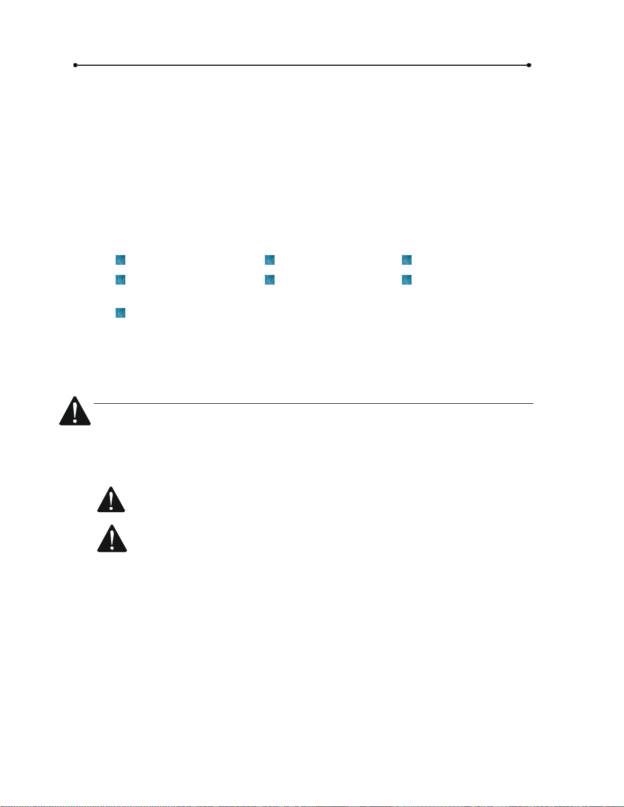
Specific safety features include:
Gate Edges Enclosed Track Vertical Posts
Guards for exposed
rollers
Screen Mesh
Important instructions follow. These instructions are intended to highlight certain safety
related issues. These instructions are not intended to be comprehensive. Because
each application is unique, it is the responsibility of the purchaser, designer, installer
and end user to ensure that the total gate system is safe for its intended use.
Photo-electric
Sensors
Instructional and
Precautionary Signage
Safety Instructions
Select instructions are highlighted with this precautionary symbol (see left margin).
Failure to follow these selected instructions can result in serious injury or death.
STEP 1: BEFORE INSTALLATION
1 Confirm gate operator model is specified by Installation and Maintenance
Manual for application type, gate size and frequency or use.
2 Confirm ALL appropriate safety features, such as gate edges, photo-electric
sensors, vertical posts and enclosed tracks, are specified.
3 Confirm gate system design reduces pinch points and protects against
entrapment.
4 Confirm gate system design has pedestrian access separate from vehicular
entrance.
5 Confirm gate system design reduces traffic backup.
6 Confirm warning signage is included in design.
7 Confirm gate moves freely before installation of operator
8 Repair or service worn or damaged gate hardware before installation of
9 To avoid installation hazards, review the gate system operation and
10 Confirm control design prohibits unauthorized use
Doc 01-20221
Rev D
operator.
installation procedures, such as manual disconnect mechanism procedure.
Page 7
Safety Information
STEP 2: DURING INSTALLATION
1 Disconnect power at service panel before making any electrical connection.
2 Avoid pinch points, be aware of all moving parts.
3 Adjust clutch or load sensing device to minimum force setting.
4 Do not over-tighten cutch or adjust force setting above minimum.
5 Install controls where user cannot touch gate while operating controls.
6 Install controls where user has full view of gate operation.
7 Install two or more warning signs on the gate to alert persons in the area of
automatic gate operation. Warning signs must be conspicuous.
8 Install operator inside fence line. DO NOT install operator on public side of
fence line.
9 Secure gate operator cover.
STEP 3: AFTER INSTALLATION
1 Test all safety features.
7
2 Train end user about basic functions and safety features of gate system.
3 Leave Installation and Maintenance Manual and Safety Instructions with
end user.
Doc 01-20221
Rev D
Page 8
8
Safety Information
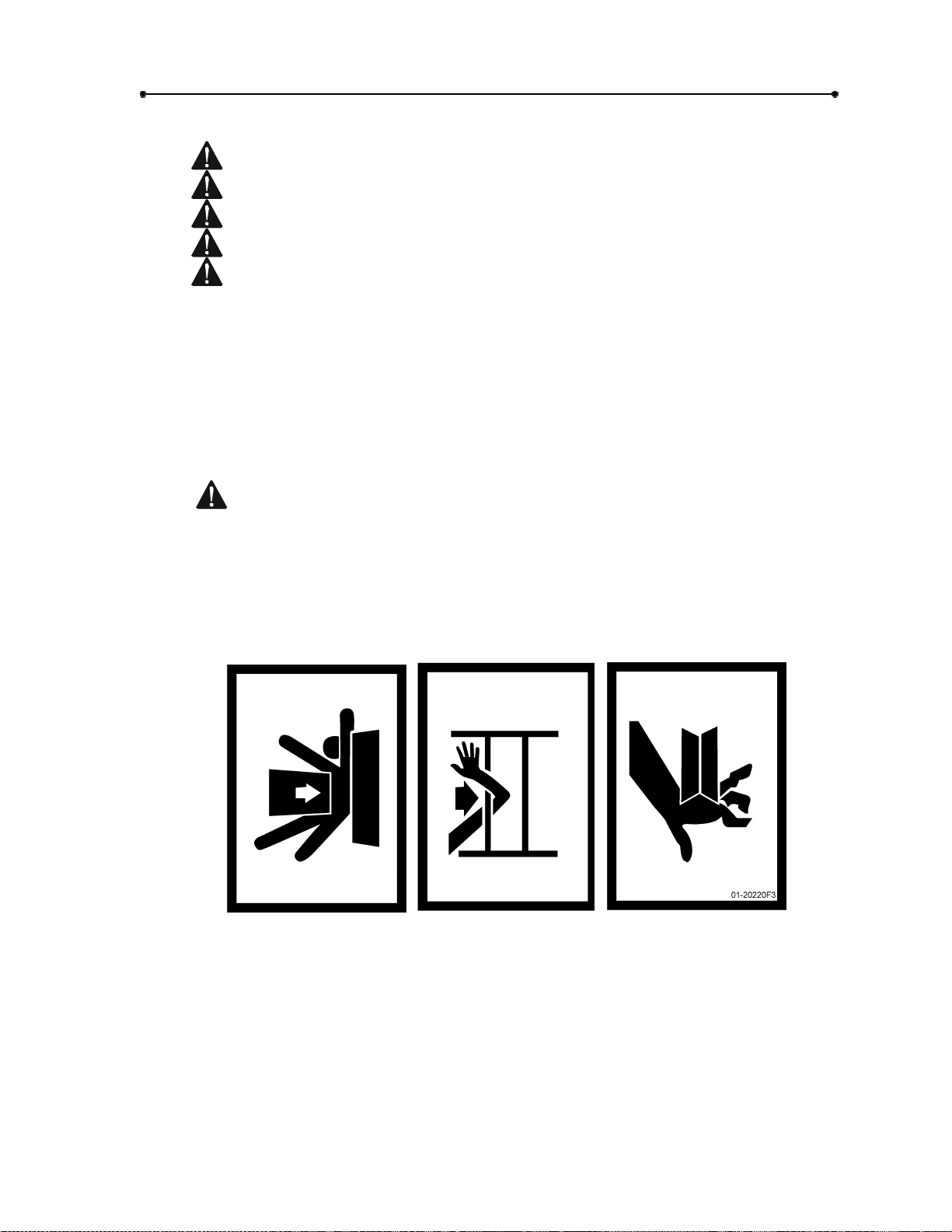
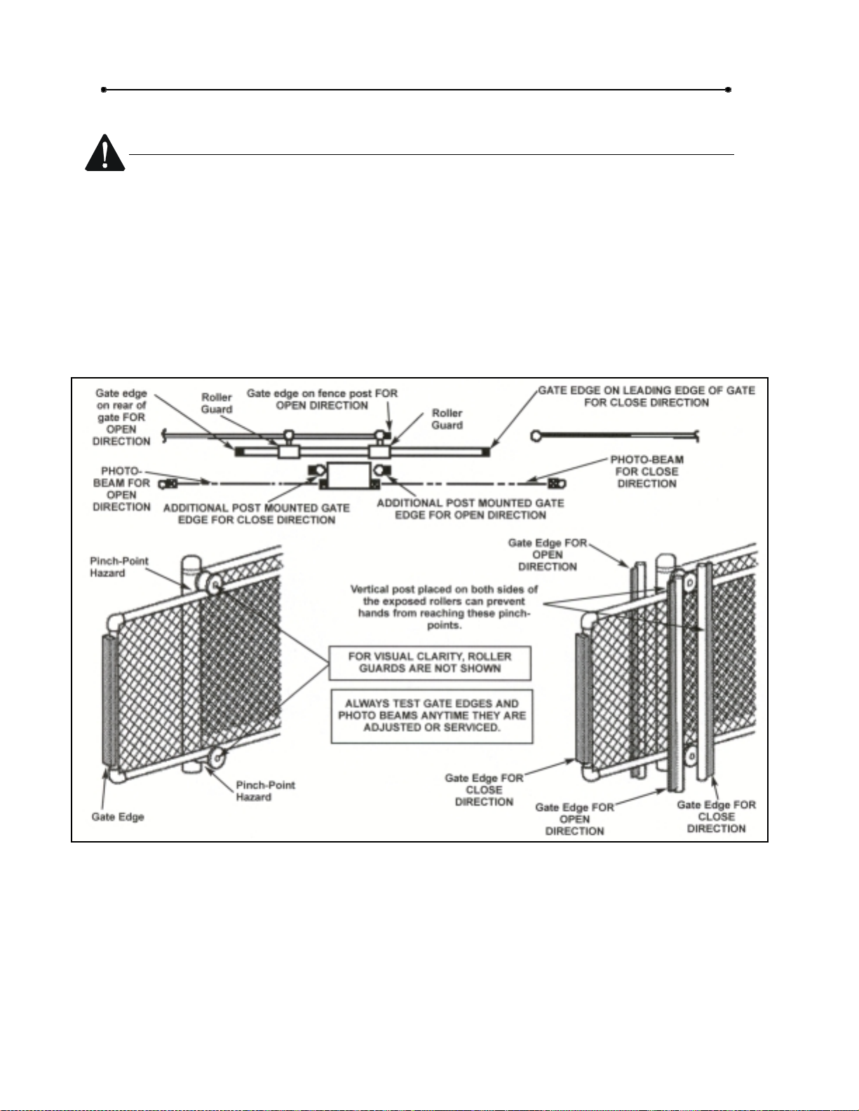
Safety Precautions for Open-Roller Gates and Ornamental “Grill Type” Gates
OPEN-ROLLER GATES
Injuries occur when people get their or feet caught between the top or bottom of the
gate and the gate roller. This potential pinch-point should be guarded against at all
times. Enclosed style gate tracks are available for refitting of these rollers from
many fence suppliers. Also, roller guards are available for installing over the
rollers.
One ore more contact sensors shall be located at the leading edge, trailing edge,
and post-mounted both inside and outside of a vehicular horizontal slide gate.
Doc 01-20221
Rev D
Figure 3
Page 9
Safety Information
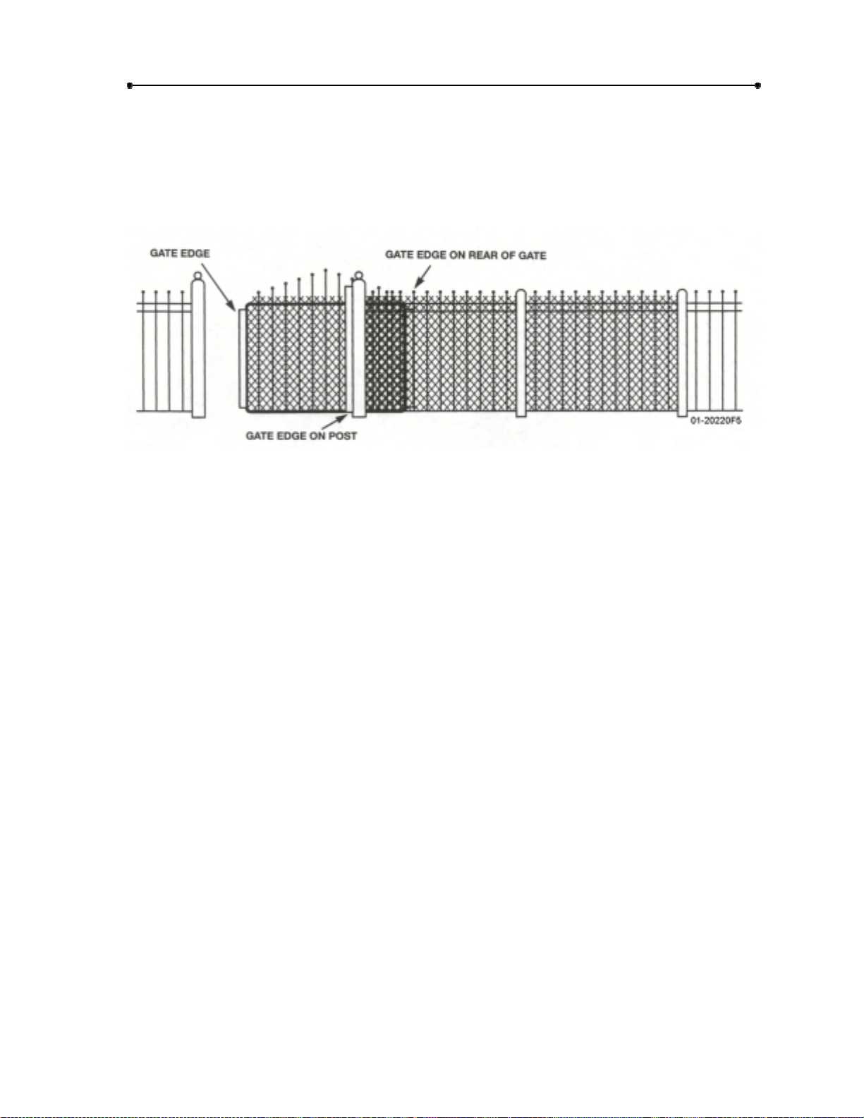
ORNAMENTAL “GRILL TYPE” GATES
Injuries occur when people put their hands and arms through openings in the grill
and the gate is operated. They cannot retract their arms and it gets caught between
the moving gate grill and the stationary fence post or fence. This potential hazard
can be averted by placing a screen mesh on the gate to prevent access through
openings anywhere the gate may travel.
Figure 4
9
Doc 01-20221
Rev D
Page 10

10
Pre-Installed Check-List
Pre-Installed Check-List
1 Check the gate. It must operate freely. If necessary, lubricate or adjust gate to
operator installation. The gate should be level and plumb.
2 Overhead, tracked, or roller tracked gates may require back frame to be constructed
to allow for drive rail attachment.
3 If wiring has already been installed, check that it meets the following wiring
specifications.
Wiring Specifications
1 Knowing operator voltage and phase, select selection that corresponds.
2 The distance shown on the chart is the length of the wire measured in feet from
the operator to the power source. (do not exceed maximum distance.)
3 If your power distance is greater than the figures shown, it is recommended that
the power utility company be notified for a service feeder. Where feasible, a
higher voltage or three-phase operator should be used.
4 When wire larger than 12 gauge is used, a separate junction box will be needed
for operator power connection. (not supplied.)
5 Select control wire gauge form chart. If greater distance or
Lighter gauge wire is required, consult manufacture.
6 Wire run calculations are based on the national electrical code, article 430,
allowing 5% voltage drop.
7 Supply voltage must be within 10% of the operator rating under load conditions.
8 Connect power accordance with local codes.
9 Wire table is based on stranded copper wire. Wire insulation must be suitable to
application.
POWER WIRING
THREE PHASE
MAX. DIST. (FT.)
VOLT.
H.P.
SINGLE UNIT
DUAL
UNIT
WIRE
GAUGE
230
1HP
343
171
12
SINGLE PHASE
MAX. DIST. (FT.)
VOLT
H.P.
SINGLE
UNIT
DUAL UNIT
WIRE
GAUGE
115
HP
56
28
12
Doc 01-20221
Rev D
Page 11

546
273
10
868
434
8
1381
690
6
460
1HP
1593
796
12
2533
1266
10
4029
2014
8
6407
3203
6
230
2HP
181
90
12
289
144
10
459
229
8
731
Pre-Installed Check-List
89
44
10
143
71
8
227
113
6
230
1HP
226
113
12
359
113
10
572
179
8
909
286
6
115
2HP
29
14
12
46
23
10
74
37
8
118
59
6
11
Doc 01-20221
Rev D
Page 12

12
Pre-Installed Check-List
365
6
460
2HP
796
398
12
1266
633
10
2014
1007
8
3203
1601
6
230
2HP
110
55
12
175
87
10
280
140
8
445
222
6
Table 3
Table 2
CONTROL WIRING
VOLTAGE MAX DIST. (FT.) WIRE GAUGE
24 vac
For longer control wiring distances, LiftMaster “Long distance Interface” (LDI) should be
used.
102 14
163 12
Table 4
Doc 01-20221
Rev D
Page 13

Installation
Installation Notes
Installation show is for a right-handed unit (on right side of gate opening when
inside looking out). Left-handed is opposite. For L.H. conversion, see page 24.
If there is existing concrete at area of unit mounting, use dimensioning
procedure described in step 1. Conduit locations may require modifications to
suit your application.
Installation
13
Step 1:
See Figure 5.
Concrete Pad
1 Layout concrete pad as detailed.
2 Locate conduit, as required, prior to pouring concrete.
3 Pour concrete, insuring that pad is level and above the ground line. Pad must
be a minimum of 24 inches in depth or below the frost line, whichever is
greater.
4 Allow concrete to set at least 2 days before installing unit.
5 Locate four (4) ½” threaded anchors (not supplied) or other means of fastening
as shown. Anchors must be positioned accurately and be secure in the
concrete.
NOTES
Always use separate conduits for power wiring and control wiring.
You may want to install extra conduit for future wiring
considerations.
For detailed information on the emergency disconnect system, see
instructions supplied with it.
This in only a suggested layout, other pad layouts are possible.
Doc 01-20221
Rev D
Page 14

14
Installation
“GATE”
SHOWN
OPEN
AS
REQ’D.
5 7/8
0
2
1
-
2 3/4”
0
2
2
1
F
ANCHOR LOCATION
MARKED “Z”
+ 7 1/2”
Z
Z
OPTIONAL EMERGENCY
DISCONNECT
26 1/2”
14”
Z
X
3”
Z
X
3 7/8”
CONDUIT
6
X
X
29 3/4”
35”
3 3/4”
2 5/8”
X = 1 3/4”
+ = CRITICAL DIMENSION
Figure 5
Doc 01-20221
Rev D
Page 15

Installation
15
Step 2:
Drive Rail
IMPORTANT NOTES
It is very important that the drive rail be:
Level and parallel to the gate and operator.
As close as possible to the 11 ½” dimension.
Very securely mounted to the gate and back frame.
1 If using your own drive rail, see detail of LiftMaster drive rail for proper
dimensions.
2 The length of the drive rail should be the gate opening width plus
2-3 feet.
3 It is suggested that the drive rail be made out of or coated with a
material that will inhibit rust.
4 If you are using the LiftMaster anti-skid tape or another means of anti-
skid, install it to the rail now.
Figure 6
01-20221F7
Doc 01-20221
Rev D
Page 16

16
Installation
Step 3:
Mounting
1 Remove the cover from the operator.
2 Carefully secure the operator to the concrete pad with the drive wheel facing the
gate.
IMPORTANT NOTE
Operator must be level and parallel with the gate and drive rail. By loosening
the bolts securing the mounting legs to the unit, the operator can be slightly
adjusted up or down. Retighten bolts.
Make sure that the drive rail and wheels are aligned properly. See detail
below. Also see page 15.
Step 4:
Vent Cap
Remove the threaded plug from the pump tank and install the vent cap in its place. Do
not throw plug away. Leave it with unit.
IMPORTANT NOTE
Never run the operator without the vent cap in place.
IMPORTANT: DO NOT
USE COVER HANDLES
TO MOVE UNIT
REMOVE BOLT TO
TAKE COVER OFF
Doc 01-20221
Rev D
LOOSEN SCREWS TO
REMOVE COVER
VENT CAP
THREADED
PLUG
TANK
01-20221F8
Figure 7
Page 17

Installation
17
Step 5:
See Figure 8.
Limit Shoes
1 Manually open the gate to the full position.
2 Locate the open limit switch lever and mark its position.
3 Manually close the gate to the full close position.
4 Locate the close limit switch lever and mark its position on the drive rail.
5 Manually open the gate about halfway. Per drawings below, measure and
drill holes. Mount both limit shoes to underside of drive rail.
IMPORTANT NOTES
The limit shoes are slotted, so minor adjustments may be made later
for the fine tuning of the full open and close position. Also, note that
the limit switches themselves may be slightly adjusted up or down.
It is highly suggested that gate stops be installed to the gate at the full
open and closed positions.
Due to the fact that this unit has no brake, there will be some gate
coasting and, depending on gate weight, it could be considerable, so it
might drift past the limits.
If coasting is a problem and a precise stop is needed, part number 410.1726
(supplied) should be installed. See directions.
Doc 01-20221
Rev D
Page 18

18
Installation
Doc 01-20221
Rev D
01-20221F9
Figure 8
Page 19

Installation
19
Step 6:
See Figure 10.
The suspension system is semi-factory set; simply loosen the suspension separate or
bolt completely. This will allow both wheels to pinch the drive rail.
If more or less pressure is required, adjust both upper and lower suspension spring lock
nuts as desired.
Suspension System
NOTE
It is suggested that the separator bolt be removed and left with unit. If it is not
removed, make sure that it can not interfere with suspension system.
IMPORTANT NOTES
Both springs should apply about the same amount of pressure.
If using the LiftMaster drive rail, make sure that the drive rail guide wheel is
positioned properly. See Figure 9.
It is very important that the suspension system is adjusted properly. This
system puts pressure on the drive wheels so they can pinch together on the
drive rail. This system also allows the drive wheels to “float” so they can follow
any slight misalignment of the drive rail. If the springs are overtightened, it will
reduce their life span. But on the other hand, if they are under-tightened, the
drive wheels may slip on the drive rail.
Doc 01-20221
Rev D
Page 20

20
Installation
Doc 01-20221
Rev D
01-20221F10
Figure 9
Page 21

Installation
21
Step 7:
The pump is equipped with a manual bypass valve. By positioning the valve handle
down (manual operation), the gate can be back-driven open or closed.
A back-up to this is the suspension separator bolt. By tightening this bolt, the drive
wheels will be pushed off the drive rail.
Manual Operation
NOTE
When manually opening or closing the gate, it is not I the beginning, easy to get
the gate started. Since fluid has accumulated in the drive motors, it will take a
good size push to get the gate started.
Figure 10
01-20221F11
Doc 01-20221
Rev D
Page 22

22
Installation
Step 8:
Most factory-installed accessories are located on or under the control panel and are
already wired into it.
Factory Installed Accessories
NOTE
By removing one bolt, the entire control panel can be pivoted out of the way.
Doc 01-20221
Rev D
Figure 11
Page 23

Installation
23
Step 9:
Electrical Wiring
Make sure power is disconnected at main power supply and at power disconnect switch
on the unit before proceeding.
1 Secure all electrical power connections to the power wiring terminal strip.
Single phase to L1, L2 and GROUND. Three phase to L1, L2, L3 and
GROUND.
2 Connect all controls to the control wiring terminal strip. Reference the electrical
diagram supplied with the unit.
IMPORTANT NOTE
On three-phase units, when unit is first run, if you can hear the pump running
but the gate does not move:
1 Make sure the manual bypass valve is in the automatic operation
position. See page 21.
2 If the bypass valve is OK, disconnect the main power supply and
reverse any two wire connections at the power terminal strip.
POWER TERMINAL
STRIP
POWER DISCONNECT
GRD.
SWITCH
CONTROL
TERMINAL
STRIP
“CONTROL”
PANEL
T3 T2
3-BUTTON
STATION
MULTIPLE
3-BUTTON
STATION
T1 L1L2L3 112
1
2
3
1
2
3
4
1
0
OPEN
STOP
CLOSE
STOP
CLOSE
2
-
2
0
OPEN
1
2
F
3
1
454
23
SINGLE INPUT
OPEN ONLY
Push button, Radio,
Loops, Keyswitch, etc.
SINGLE INPUT
OPEN/CLOSE
Push button, Radio,
Loops, Keyswitch, etc.
NOTE:
Must be used with a
“Stop” control for full
control of the gate.
REVERSE DEVICE
Edges, Loops,
Photo Cells, etc.
10
610
1
4
16
4
5
Figure 12
Step 10:
Reversing Device
Due to the amount of force this opener can generate, please install a sensing edge on
the gate. It is imperative and beneficial to the customer, LiftMaster, and yourself that
the installation is as safe as possible.
Doc 01-20221
Rev D
Page 24

24
Installation
Left Hand/Right Hand Conversion
When switching the unit from right hand to left hand or vice-versa:
1 Put the by-pass valve handle in the manual position (down).
2 Push in the directional valve manual override 5 times.
3 Remove and reverse the two (2) hoses, shown below.
4 Return the by-pass valve to the automatic position (up).
5 The limit switch connectors, at the top of the control panel must be reversed.
Doc 01-20221
Rev D
01-212 21F14
Figure 13
Page 25

Left Hand / Right Hand Conversion
Operator Check-Out
OPERATED CHECK-OUT WITH ALL CONTROLS CONNECTED
1 Switch the power disconnect switch to “on”.
2 Press the “open” button, allow unit to run about 10 seconds, then press the
“stop” button.
NOTE
When unit is first started, gate may not move immediately. This is
caused by the fluid being circulated through the system.
3 Press the “close” button. Allow unit to run until the open limit switch shuts the
system down.
25
Press
4
the system down.
5 Press the “close” button and test all safety features that have been installed.
6 Check out all optional controls that have been installed.
7 Test the 90-second run feature. Do this by positioning the manual bypass
valve handle to the manual position. Activate the unit. The unit will run but
the gate should not move. After approximately 90 seconds, the unit should
automatically shut off.
8 Check out manual operation of the gate.
9 Return the bypass valve handle to the automatic operation position.
the “open” button. Allow unit to run until the open limit switch shuts
NOTE
For troubleshooting, see guide supplied. It is recommended that the
M.R.D be adjusted to 2 times run time of gate. Example: if gate takes 15
seconds to open, then set M.R.D. to 30 seconds.
Doc 01-20221
Rev D
Page 26

26
Operator Check-Out
And Finally…
Install gate caution signs on both the inside and outside of the gate.
Re-install the control panel cover and the operator cover.
If the operator got greasy or dirty, please clean it.
Clean-up the area around the operator and gate.
Look around for any of your tools that may be left.
Please, leave the customer both this manual and the troubleshooting guide.
Let the customer know that you’re done and possibly review with them the
system that is installed. Go over how it works, accessories and their locations,
maintenance requirements, etc.
Required Maintenance Services
Check at least once every 6 months
Gate
Frame/Bolts
Electrical
Safety Systems
Fluid Level
Fittings
Drive Rail
Drive Wheels
Manual Operation
Inspect for wear or damage
Check & tighten
Inspect all wire connections
Check & test
Keep at lease ¾ full +
Check for leaks
Check for damage
Check for wear
Check & test
√
√
√
!
√
√
√
√
√
!Check at least once per month.
CAUTION
When servicing, always disconnect operator from power.
Doc 01-20221
Rev D
Table 5
Use only “ATF” automatic transmission fluid.
For complete maintenance information, see the maintenance manual.
Page 27

COPYRIGHT 2001
ALL RIGHTS RESERVED
This document is protected by copyright and may not be copied or adapted without the prior written
consent of LiftMaster. This documentation contains information proprietary to LiftMaster and such
information may not be distributed without the prior written consent of LiftMaster. The software and
firmware included in the LiftMaster product as they relate to this documentation are also protected by
copyright and contain information proprietary to LiftMaster.
FOR TECHNICAL SUPPORT
Call our toll free numbers:
(800) 323-2276
(800) 998-9197
Installation and service information is
available six days a week.
TO ORDER REPAIR PARTS
Call our toll free numbers:
(800) 528-2806
(800) 998-9197
Prepare to provide the following
information when ordering repair parts:
" Part Number
" Part Name
" Model Number
 Loading...