

Page 1
CONTROLLER BOARD
GL
Serial # ________________________
(located on electrical box cover)
Installation Date __________________
2 YEAR WARRANTY
MODEL HS670 IS FOR VEHICULAR PASSAGE GATES ONLY AND
ARE NOT INTENDED FOR PEDESTRIAN PASSAGE GATE USE
MODEL HS670
HEAVY DUTY HYDRAULIC SLIDEGATEOPERATOR
Page 2
2
CARTON INVENTORY
Before beginning your installation check that all components
were supplied and received undamaged. Refer to list below
for factory supplied parts.
Description Qty.
Bolt 1/4-20 (for Limit Shoe) 4
Lockwasher 1/4 4
Hex Nut 1/4-20 4
Screw #10-24 (for Gate Stop) 4
Lockwasher #10 4
Hex Nut #10-24 4
Limit Shoe 2
Gate Warning Sign 2
Vent Cap 1
Gate Stops 2
PBS, Stop 1
HARDWARE KIT
When you see the above Safety Symbols and Signal Words on
the following pages, they will alert you to the possibility of
SERIOUS INJURY or DEATH if you do not comply with the
warnings that accompany them. The hazard may come from
something mechanical or from electric shock. Read the warnings
carefully.
When you see this Signal Word on the following pages, it will
alert you to the possibility of damage to your gate and/or the gate
operator if you do not comply with the cautionary statements that
accompany it. Read them carefully.
IMPORTANT NOTE
• BEFORE attempting to install, operate or maintain the operator,
you MUST read and fully understand this manual and follow all
safety instructions.
• DO NOT attempt repair or service of your commercial door and
gate operator unless you are an Authorized Service Technician.
TABLE OF CONTENTS
OPERATOR SPECIFICATIONS
Carton Inventory . . . . . . . . . . . . . . . . . . . . . . . . . . . . . . . . . . . . .2
Operator Features . . . . . . . . . . . . . . . . . . . . . . . . . . . . . . . . . . . .3
Operator Dimensions and Horsepower Chart . . . . . . . . . . . . . . .4
UL325 Model Classifications . . . . . . . . . . . . . . . . . . . . . . . . . . . .5
OPERATOR WARNINGS
Safety Installation Information . . . . . . . . . . . . . . . . . . . . . . . . . .6
Suggested Entrapment Protection Device Locations . . . . . . . . . .7
Safety Precautions for Open Roller Gates . . . . . . . . . . . . . . . . . .8
Warning Sign Placement . . . . . . . . . . . . . . . . . . . . . . . . . . . . . . .8
INSTALLATION
Concrete Pad . . . . . . . . . . . . . . . . . . . . . . . . . . . . . . . . . . . . . . . .9
Drive Rail . . . . . . . . . . . . . . . . . . . . . . . . . . . . . . . . . . . . . . . . . . .9
Operator Mounting . . . . . . . . . . . . . . . . . . . . . . . . . . . . . . . . . . .9
Vent Cap . . . . . . . . . . . . . . . . . . . . . . . . . . . . . . . . . . . . . . . . . .10
Limit Shoes . . . . . . . . . . . . . . . . . . . . . . . . . . . . . . . . . . . . . . . .10
Gate Stops . . . . . . . . . . . . . . . . . . . . . . . . . . . . . . . . . . . . . . . . .11
Suspension System . . . . . . . . . . . . . . . . . . . . . . . . . . . . . . . . . .11
Manual Operation . . . . . . . . . . . . . . . . . . . . . . . . . . . . . . . . . . .11
WIRING
Power Wiring Installation . . . . . . . . . . . . . . . . . . . . . . . . . . . . .12
On/Off Switch Power Wiring . . . . . . . . . . . . . . . . . . . . . . . . . . .13
ADJUSTMENT
Hall Effect Sensor Adjustment . . . . . . . . . . . . . . . . . . . . . . . . . .14
Force Adjustment . . . . . . . . . . . . . . . . . . . . . . . . . . . . . . . . . . . .14
PROGRAMMING
UL325 Entrapment Protection . . . . . . . . . . . . . . . . . . . . . . . . . .15
Control Board Illustration . . . . . . . . . . . . . . . . . . . . . . . . . . . . .16
Program Settings (DIP Switch) . . . . . . . . . . . . . . . . . . . . . .17-18
Programming the Radio Receiver . . . . . . . . . . . . . . . . . . . . . . .19
OPTIONAL CONTROL DEVICES
Sequenced Access Management System (SAMS) . . . . . . . . . . .20
Accessory Wiring . . . . . . . . . . . . . . . . . . . . . . . . . . . . . . . . . . .21
Control Connection Diagrams . . . . . . . . . . . . . . . . . . . . . . . . . .22
OPERATION AND MAINTENANCE
Important Safety Instructions . . . . . . . . . . . . . . . . . . . . . . . . . .23
TROUBLESHOOTING
GL Board Features . . . . . . . . . . . . . . . . . . . . . . . . . . . . . . . . . . .24
Electrical Troubleshooting . . . . . . . . . . . . . . . . . . . . . . . . . .25-26
Hydraulic System Troubleshooting . . . . . . . . . . . . . . . . . . . . . .27
Mechanical Troubleshooting . . . . . . . . . . . . . . . . . . . . . . . . . . .27
Hydraulic System Information . . . . . . . . . . . . . . . . . . . . . . .28-29
SINGLE PHASE WIRING DIAGRAM
. . . . . . . . . . . . .30
THREE PHASE WIRING DIAGRAM
. . . . . . . . . . . . . .31
ELECTRICAL BOX
. . . . . . . . . . . . . . . . . . . . . . . . . . .32
ILLUSTRATED PARTS
. . . . . . . . . . . . . . . . . . . . . . . .33
WARRANTY POLICY
. . . . . . . . . . . . . . . . . . . . . . . . .34
OPERATOR NOTES
. . . . . . . . . . . . . . . . . . . . . . . . . .35
REPAIR PARTS AND SERVICE
. . . . . . . . . . . . . . . . .36
Mechanical
Electrical
WARNING
CAUTION
WARNING
WARNING
WARNING
WARNING
WARNING
Page 3
3
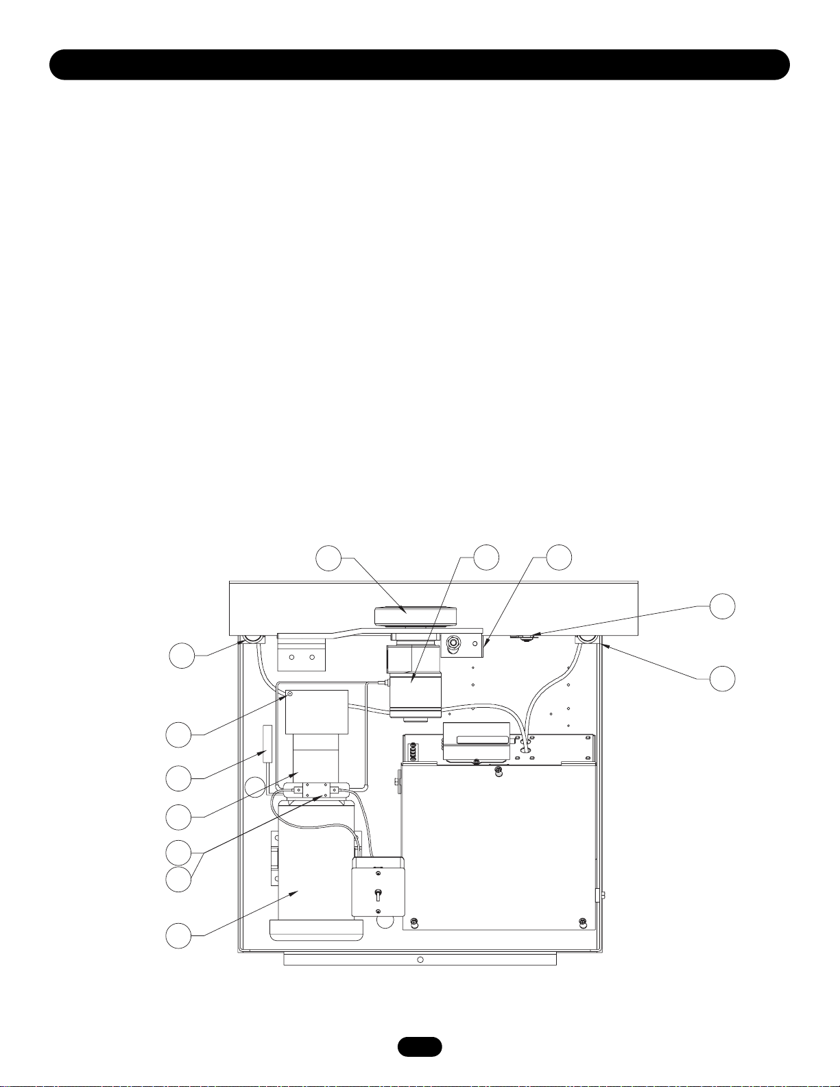
G. LIMIT SWITCH
All limit switches are oil tight and watertight, and of NEMA 3, 4,
and 13 construction. Open switch for right hand, close switch for
left hand.
H. DRIVE WHEELS
Drive wheels are constructed of polyurethane material on a steel
hub and have a hardness factor of 95. HS670 1HP = 1 1/2" wide,
6" diameter; HS670 2HP= 2" wide, 6" diameter.
I. HYDRAULIC MOTOR
Roller vane, free wheeling type with a displacement of 12 cubic
inches per revolution.
J. SUSPENSION SYSTEM
Incorporates two compression springs. HS670 1HP and HS670
2HP use different compression springs. See also page 11.
K. HALL EFFECT (RPM) SENSOR ASSEMBLY
OPERATOR SPECIFICATIONS
OPERATOR FEATURES
A. MOTOR 1 AND 2 HP
The motors used in the HS670 GC and HS670 GI are T.E.F.C.
(totally enclosed, fan cooled) and operate at 3450 R.P.M. They
incorporate a built-in manually resettable thermal overload.
B. DIRECTIONAL VALVE
Directional valve is 3 position, 4 way. It incorporates 2 solenoids
which are 24 VDC. The power required for operation is rectified
from 24 VAC.
C. HYDRAULIC BRAKE
Dual valve system limits gate over travel.
D. BYPASS VALVE
Incorporates a handle at side of pump. When positioned
downward, it will allow manual operation of the gate.
E. RELIEF VALVE
Built into pump. Set at 600 p.s.i. for HS670 1HP and 1500 p.s.i.
for HS670 2HP.
F. VENT CAP
When removed, you may add hydraulic oil. Must be on during
operator operation.
H
G
F
D
E
B
C
A
I J
K
G
Page 4
4
OPERATOR SPECIFICATIONS
MODEL HS670 GC
• 1 HP Motor
Gate Speed – 12"/sec.
Maximum Gate Weight – 3000 lbs.
Maximum V-Track Gate Width – 80 ft.
MODEL HS670 GI
• 1 HP Motor
Gate Speed – 18"/sec.
Maximum Gate Weight – 3000 lbs.
Maximum V-Track Gate Width – 80 ft.
MODEL HS670 GI
• 2 HP Motor
Gate Speed – 18"/sec.
Maximum Gate Weight – 5000 lbs.
Maximum V-Track Gate Width – 80 ft.
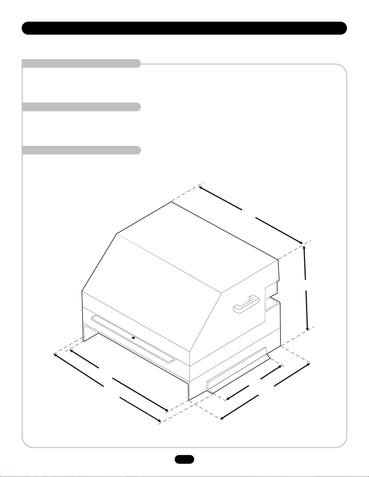
OPERATOR DIMENSIONS AND HORSEPOWER CHART
29-3/4"
31-3/4"
27"
19-3/4"
14"
26-1/2"
Page 5
5
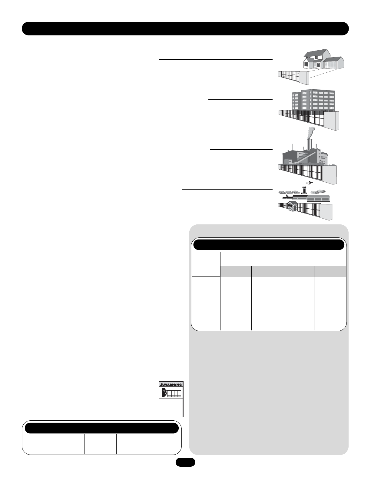
CLASS I – RESIDENTIAL VEHICULAR GATE OPERATOR
A vehicular gate operator (or system) intended for use in a home of one-to four single family dwellings,
or a garage or parking area associated therewith.
CLASS II – COMMERCIAL/GENERAL ACCESS VEHICULAR GATE OPERATOR
A vehicular gate operator (or system) intended for use in a commercial location or building such as a
multi-family housing unit (five or more single family units) hotel, garage, retail store or other building
servicing the general public.
CLASS III – COMMERCIAL/GENERAL ACCESS VEHICULAR GATE OPERATOR
A vehicular gate operator (or system) intended for use in a industrial location or building such as a
factory or loading dock area or other location not intended to service the general public.
CLASS IV – RESTRICTED ACCESS VEHICULAR GATE OPERATOR
A vehicular gate operator (or system) intended for use in a guarded industrial location or building such
as an airport security area or other restricted access locations not servicing the general public, in which
unauthorized access is prevented via supervision by security personnel.
SAFETY ACCESSORY SELECTION
All UL325 compliant LiftMaster gate operators will accept external
entrapment protection devices to protect people from motorized
gate systems. UL325 requires that the type of entrapment
protection correctly matches each gate application. Below are the
six types of entrapment protection recognized by UL325 for use
on this operator.
ENTRAPMENT PROTECTION TYPES
Type A: Inherent obstruction sensing system, self-contained
within the operator. This system must sense and initiate
the reverse of the gate within two seconds of contact
with a solid object.
Type B1: Connections provided for a non-contact device, such as
a photo eye can be used as a secondary protection.
Type B2: Connections provided for a contact sensor. A contact device
such as a gate edge can be used for secondary protection.
Type C: Inherent adjustable clutch or pressure relief valve.
Type D: Connections provided for a control requiring continuous
pressure to operate the operator open and close.
Type E: Built-in audio alarm (e.g., sirens, horns or buzzers).
NOTES:
UL requires that all installations must have warning signs
placed in plain view on both sides of the gate to warn
pedestrians of the dangers of motorized gate systems.
Model HS670 meets the following specifications:
UL325 ENTRAPMENT PROTECTION REQUIREMENTS
In order to complete a proper installation you must satisfy the
entrapment protection chart shown above. That means that
the installation must have one primary means of entrapment
protection and one independent secondary means of
entrapment protection. Both primary and secondary
entrapment protection methods must be designed, arranged
or configured to protect against entrapments in both the open
and close directions of gate travel.
For Example: For a slide gate system that is installed on a
single-family residence (UL325 Class I) you must provide the
following: As your primary type of entrapment protection you
must provide Type A inherent (built into the operator)
entrapment sensing and at least one of the following as your
secondary entrapment protection: Type B1- Non-contact
sensors such as photo-eyes, Type B2- Contact sensors such
as gate edges or Type D- Constant pressure control.
GATE OPERATOR ENTRAPMENT PROTECTION
Class
I & II
Class III
Class IV
A, B1, B2,
C or D
A, B1, C,
D or E
A, B1, B2,
D or E
A, B1, B2
or D
A, B1 or B2A, B1, B2,
D or E
A, B1, B2
or C
A, B1, B2
C or D
A or C
B1, B2
or D
A
UL325 Slide Gate Operator Swing & Gate Barrier
Installation (Arm) Operator
Class
Primary
Type
Secondary
Type
Secondary
Type
Primary
Type
D or E
OPERATOR SPECIFICATIONS
MODEL CLASS 1 CLASS 2 CLASS 3 CLASS 4
HS670 GC
" " " "
HS670 GI N/A N/A
" "
UL325 MODEL CLASSIFICATIONS
Moving Gate Can Cause
Injury or Death
KEEP CLEAR! Gate may move at any
time without prior warning.
Do not let children operate the gate or
play in the gate area.
This entrance is for vehicles only
Pedestrians must use separate entrance
Page 6

6
SAFETY INSTALLATION INFORMATION
1. Vehicular gate systems provide convenience and security. Gate systems are comprised of many component parts. The gate
operator is only one component. Each gate system is specifically designed for an individual application.
2. Gate operating system designers, installers and users must take into account the possible hazards associated with each individual
application. Improperly designed, installed or maintained systems can create risks for the user as well as the bystander. Gate
systems design and installation must reduce public exposure to potential hazards.
3. A gate operator can create high levels of force in its function as a component part of a gate system. Therefore, safety features
must be incorporated into every design. Specific safety features include:
• Gate Edges • Guards for exposed rollers • Photoelectric Sensors
• Screen Mesh • Vertical Posts • Instructional and Precautionary Signage
4. Install the gate operator only when:
a. The operator is appropriate for the construction and the usage class of the gate.
b. All openings of a horizontal swing gate are guarded or screened from the bottom of the gate to a minimum of 4' (1.2 m) above
the ground to prevent a 2 1/4" (57.15 mm) diameter sphere from passing through the openings anywhere in the gate, and in
that portion of the adjacent fence that the gate covers in the open position.
c. All exposed pinch points are eliminated or guarded, and guarding is supplied for exposed rollers.
5. The operator is intended for installation only on gates used for vehicles. Pedestrians must be supplied with a separate access
opening.
6. The gate must be installed in a location so that enough clearance is supplied between the gate and adjacent structures when
opening and closing to reduce the risk of entrapment. Swinging gates shall not open into public access areas.
7. The gate must be properly installed and work freely in both directions prior to the installation of the gate operator.
8. Controls must be far enough from the gate so that the user is prevented from coming in contact with the gate while operating the
controls.
9. Controls intended to be used to reset an operator after 2 sequential activations of the entrapment protection device or devices
must be located in the line of sight of the gate, or easily accessible controls shall have a security feature to prevent unauthorized
use.
10. All warning signs must be installed where visible, on each side of the gate.
11. For a gate operator utilizing a non-contact sensor:
a. See instructions on the placement of non-contact sensor for each type of application.
b. Care shall be exercised to reduce the risk of nuisance tripping, such as when a vehicle trips the sensor while the gate is still
moving.
c. One or more non-contact sensors shall be located where the risk of entrapment or obstruction exists, such as the perimeter
reachable by a moving gate or barrier.
12. For a gate operator utilizing a contact sensor such as an edge sensor:
a. A hard wired contact sensor shall be located and its wiring arranged so the communication between the sensor and the gate
operator is not subject to mechanical damage.
b. A wireless contact sensor such as the one that transmits radio frequency (RF) signals to the gate operator for entrapment
protection functions shall be located where the transmission of the signals are not obstructed or impeded by building
structures, natural landscaping or similar obstruction. A wireless contact sensor shall function under the intended end-use
conditions.
c. One or more contact sensors shall be located at the leading edge, trailing edge and post mounted both inside and outside of a
vehicular horizontal slide gate.
d. One or more contact sensors shall be located at the bottom edge of a vehicular vertical lift gate.
e. One or more contact sensors shall be located on the inside and outside leading edge of a swing gate. Additionally, if the bottom
edge of a swing gate is greater than 6" (152 mm) above the ground at any point in its arc of travel, one or more contact
sensors shall be located on the bottom edge.
OPERATOR WARNINGS
Page 7
7
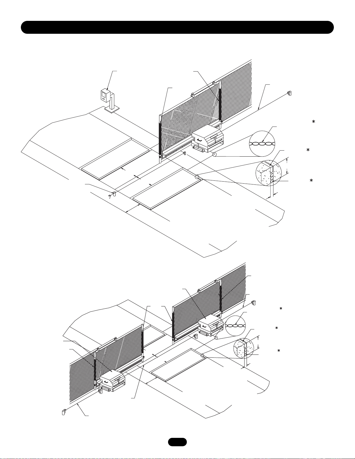
Close
Edge
Open
Edge
Run Twisted Wire
From Loop
To Detector
Seal Loops
4'
4'
Typical
4'
Typical
Interrupt
Loop
Photo Eye For
Close Cycle
4'
Typical
STREET
8'
Sentex Telephone Entry
System / Access Control
COMPLEX
OR
PARKING LOT
Interrupt
Loop
Loop Wire
Layer
1/4" Or As Required
For Loop Wire Width
1-1/2"
Photo Eye For
Open Cycle
Typical
4'
Typical
6"
Interrupt
Loop
Second
Unit
Open
Edge
Photo Eyes For
Close Cycle
Photo Eyes For
Open Cycle
STREET
1-1/2"
COMPLEX
OR
PARKING LOT
Interrupt
Loop
4'
Typical
6'
12'
Typical
4'
Typical
Loop Wire
Layer
1/4" Or As Required
For Loop Wire Width
Master
Unit
Close
Edge
Run Twisted Wire
From Loop
To Operator
Seal Loops
Photo Eye For
Open Cycle
Open Edge
*Refer to loop manufacturer’s instructions for detailed installation and loop wiring instructions.
GATE SYSTEM (MASTER/SECOND SLIDE GATE)
GATE SYSTEM (COMMERCIAL SLIDE GATE)
OPERATOR WARNINGS
SUGGESTED ENTRAPMENT PROTECTION DEVICE LOCATIONS
Page 8
8
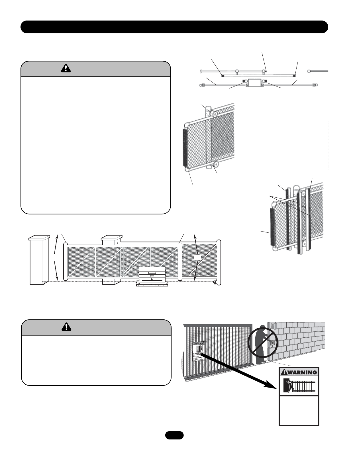
NOT FOR USE AS PEDESTRIAN PASSAGE! This operator is
intended for vehicular use only. To prevent INJURY to pedestrians,
a separate pedestrian access should be supplied, visible from the
gate. Locate the pedestrian access where there is not a chance of
INJURY at any point during full movement of the gate.
WARNING SIGN PLACEMENT
SAFETY PRECAUTIONS FOR OPEN ROLLER GATES
AND ORNAMENT “GRILL TYPE” GATES
To prevent SERIOUS INJURY or DEATH from a moving gate:
• Install Warning signs on EACH side of gate in PLAIN VIEW.
• Permanently secure each Warning sign in a suitable
manner using fastening holes.
• Do NOT mount accessories that are accessible through
gate.
• Injuries occur when people get their hands or feet caught
between the top or bottom of the gate and the gate roller.
These potential pinch-points should be guarded against at all
times. Enclosed style gate tracks are available for refitting of
these rollers from many fence suppliers. Also, roller guards
are available for installing over the rollers.
• UL325 requires that, when used, contact sensors shall be
located at the leading edge, trailing edge, and be post
mounted both inside and outside of a vehicular horizontal
slide gate. Non-contact sensors such as photo eyes must
protect during both open and close gate cycles.
• Injuries occur when people put their hands and arms
through openings in the grill while the gate is operating.
They cannot retract their arm and it gets caught between the
moving gate grill and the stationary fence post or fence. This
potential hazard can be averted by placing a 4' screen mesh
on the gate to prevent access through openings anywhere
the gate may travel. See Safety Brochure for details.
To prevent entrapment injuries, mount controls at least 6'
from the gate or any moving parts of the gate.
WARNING
WARNING
WARNING
WARNING
OPERATOR WARNINGS
Gate Edge on
Rear of Gate for
Open Direction
Photo Beam
for Open
Direction
Pinch-Point
Hazard
Gate Edge
Gate Edge on Fence
Post for Open Direction
Unit
Additional Post Mounted Gate
Edge for Close Direction
Photo Beams Anytime They Are
Pinch-Point
Hazard
Vertical Post Placed on Both
Sides of the Exposed
Rollers Can Prevent Hands
From Reaching These
Pinch-Points
Gate Edge
for Open Direction
Gate Edge on
Leading Edge of Gate
for Close Direction
Photo Beam for
Close Direction
Additional Post Mounted Gate
Edge for Open Direction
Always Te st Gate Edges and
Adjusted or Serviced
Gate Edge
for Close
Direction
Open Gate Edge
OR
Unit
Close Photo Beam
Open Gate Edge
OR
Open Photo Beam
Gate Edge for
Close Direction
Moving Gate Can Cause
Injury or Death
KEEP CLEAR! Gate may move at any
time without prior warning.
Do not let children operate the gate or
play in the gate area.
This entrance is for vehicles only
Pedestrians must use separate entrance
Page 9
9
NOTES: Installation shown is for a right-handed unit (on right
side of gate opening when inside looking out). Left-handed is
opposite. For left-handed conversion, see page 17.
If there is suitable existing concrete at area of unit mounting, use
dimensioning procedure described in step 1. Conduit locations
may require modifications to suit your application.
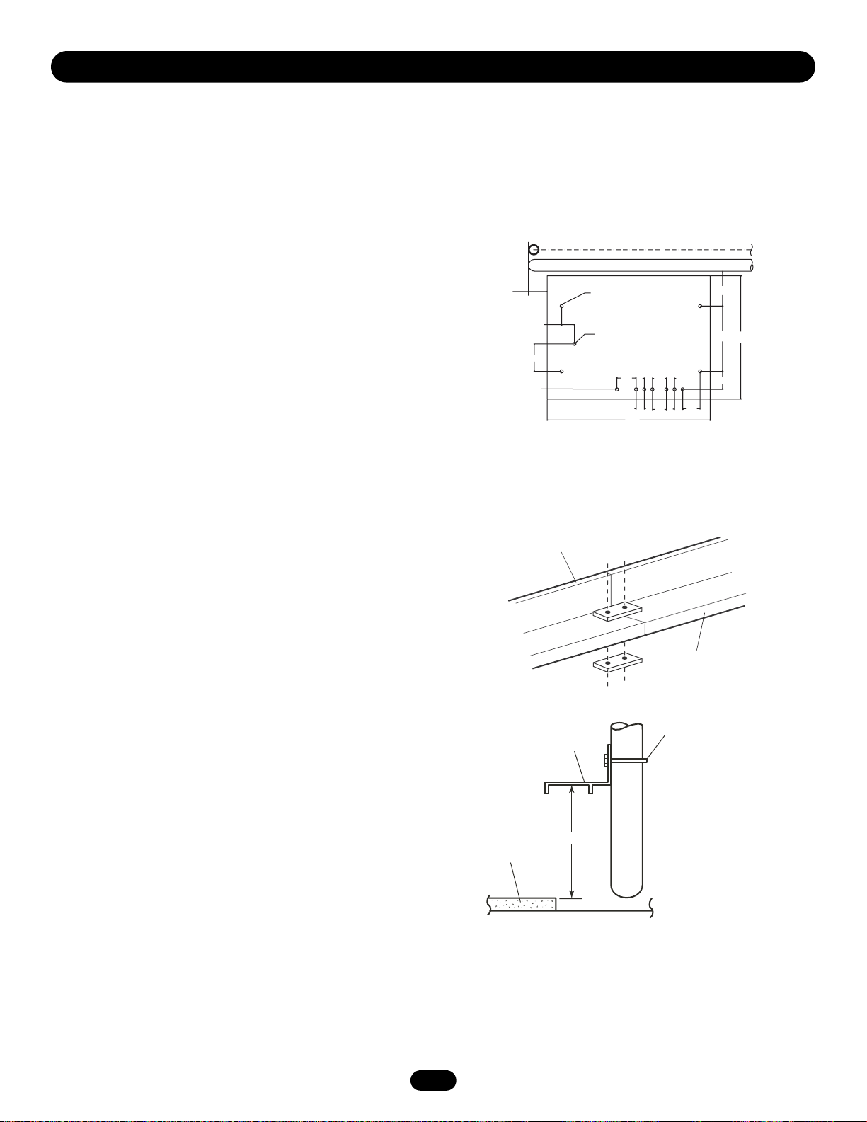
CONCRETE PAD
1. Layout concrete pad as detailed.
2. Locate conduit, as required, prior to pouring concrete.
3 Pour concrete pad. The pad must be level and above the
ground line. Pad must be a minimum of 24" in depth or below
the frost line, whichever is greater.
4. Allow concrete to set at least 2 days before installing unit.
5. Locate (4) 1/2" concrete anchors (not provided ) or other
means of fastening as shown. Anchors must be positioned
accurately and secure in the concrete.
NOTE: Always use separate conduits for power wiring and
control wiring.You may want to install extra conduit for future
wiring considerations. For detailed information on the emergency
disconnect system, see instructions provided with it. This is only
a suggested layout, other pad layouts are possible.
DRIVE RAIL
1. Mark the location to install drive rail 11-1/2" from the top of
concrete pad. The drive rail should be the gate opening width
plus 3' to 4'. The drive rail must be level and parallel to the
gate and operator.
2. Fasten the drive rail securely to the gate and backframe.
IMPORTANT NOTE: Make sure that the drive rail and wheels are
aligned properly.
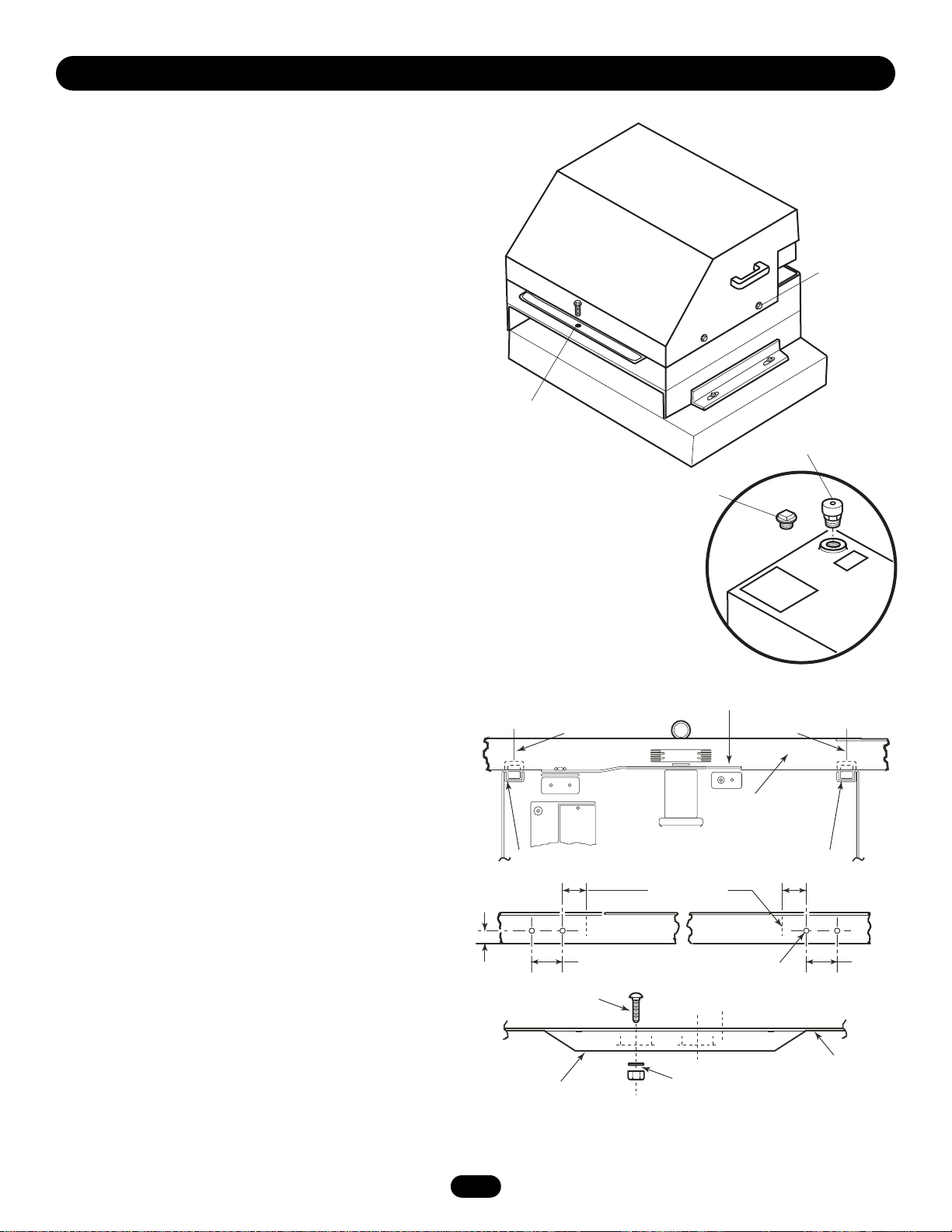
OPERATOR MOUNTING
1. Remove cover by loosening bolts on each side of cover and
remove bolt from the front of the cover. Lift cover off.
2. Secure operator to the concrete pad using (4) 1/2" concrete
anchors (not provided) with the drive wheels facing the gate.
The operator must be level and parallel with the gate and drive
rail.
NOTE: Loosen the bolts that secure the mounting legs to the unit.
The distance between the operator and the rail can then be
slightly adjusted. After adjustment, retighten the bolts.
INSTALLATION
“Gate”
Shown
Open
As
Required
2.75
5.88
Power Conduit
Entrance
Drive Rail
Section
Anchor Location
Marked "Z"
Z
Optional Emergency
Disconnect
Z
4.13
To Attach Drive
Rails Together:
1.75
35.00
1.75
3.00
1.75
1.75
Drive Rail
Section
3.75
Z
Z
+7.50
14.00
26.50
3.88
+ = Critical Dimension
Mounting Hardware
Optional
Drive Rail
11-1/2"
Pad
By Others
Page 10
10
INSTALLATION
VENT CAP
1. Remove the threaded plug from the pump tank.
2. Install the vent cap.
NOTE: Never run the operator without the vent cap installed.
LIMIT SHOES
NOTE: The limit shoes are slotted, so minor adjustments may be
made later for the fine tuning of the fully open and close
positions. Also, note that the limit switches themselves may be
slightly adjusted up or down.
1. Cut wire ties to release limit switch levers and RPM assembly
to the up right position. These items are held down by wire ties
to facilitate for initial gate installation.
2. Manually open the gate to the full position.
3. Locate the open limit switch lever and mark its position.
4. Manually close the gate to the full close position.
5. Locate the close limit switch lever and mark its position on the
drive rail.
6. Manually open the gate about halfway. Measure and drill holes
to mount limit shoes
7. Secure both limit shoes to underside of drive rail.
NOTE: It is highly suggested that gate stops be installed to the
gate at the fully open and closed positions. See next page for
installation instructions.
IMPORTANT: Do Not
Use Cover Handles
to Move Unit
Remove Bolt to
Take Cover Off
Threaded
Plug
Ta nk
Vent Cap
Loosen Screw to
Remove Cover
TOP
VIEW
TOP
VIEW
SIDE
VIEW
1-1/16"
RPM Assembly
Mark Centerline Mark Centerline
Drive Rail
Limit Switch Limit Switch
2"
3"
1/4"-20 Screw
Limit Shoe
Centerline Marks
Washer & Nut
2"
9/32" Diameter
Holes
3"
Bottom of
Drive Rail
Page 11
11
INSTALLATION
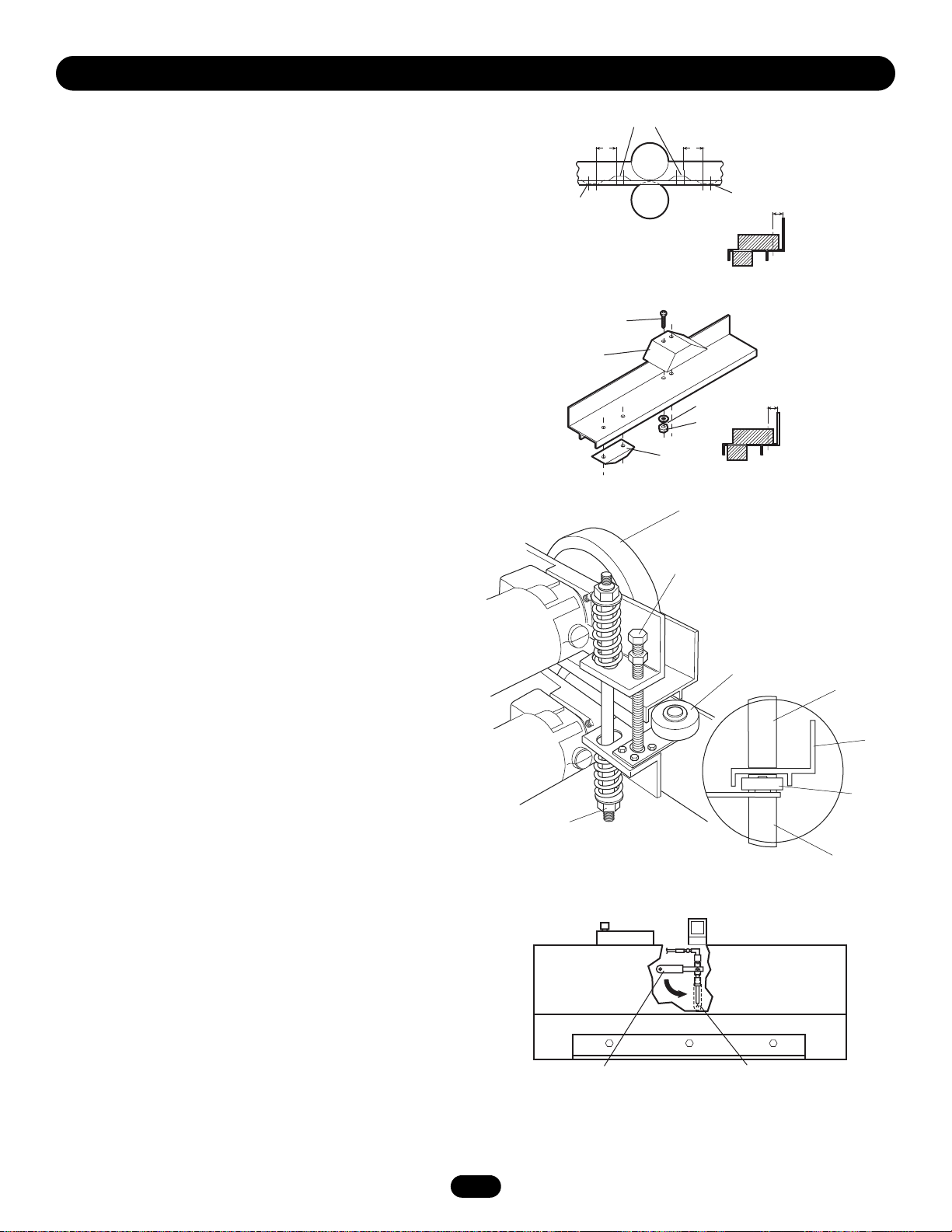
GATE STOPS
1. When properly installed the gate will open or close in
approximately 3" to 4" after limit shoe shuts the unit off, the
“gate stop” will contact the upper drive wheel stopping the
gate.
2. After operator has been installed the limit shoes have been
attached to the top of the drive rail, locate and install the (2)
“gate stops” to the top of the drive rail.
NOTE: The 7" dimension is a reference. You may have to adjust
this slightly for your particular application.
SUSPENSION SYSTEM
1. The suspension system is semi-factory set; simply loosen the
suspension separator bolt completely. This will allow both
wheels to pinch the drive rail.
NOTE: It is suggested that the separator bolt be removed and left
with unit. If it is not removed, make sure that it can not interfere
with suspension system.
2. If more or less pressure is required, adjust both upper and
lower suspension spring lock nuts as desired. Both springs
should apply about the same amount of pressure.
IMPORTANT:
If using the LiftMaster drive rail, make sure that the drive rail
guide wheel is positioned properly.
It is very important that the suspension system is adjusted
properly. This system puts pressure on the drive wheels so they
can pinch together on the drive rail. This system also allows the
drive wheels to “float” so they can follow any slight misalignment
of the drive rail. If the springs are over tightened, it will reduce
their life span. But, on the other hand, if they are under tightened,
the drive wheels may slip on the drive rail.
MANUAL OPERATION
NOTE: When manually opening or closing the gate, it is not, in
the beginning, easy to get the gate started. Since fluid has
accumulated in the drive motors, it may take more force to get
the gate started.
The pump is equipped with a manual bypass valve. By positioning
the valve handle down (manual operation), the gate can be
manually opened or closed.
NOTE: A back-up to this is the suspension separator bolt. By
tightening this bolt, the drive wheels will be pushed off by the
drive rail.
Limit
Shoe
Gate Stop
Lock Adjustment
Lower Nut
(Use 3/4" Wrench)
7"
Screw
Gate Stops
Limit Shoe
7"
Limit
11/16"
Shoe
11/16"
Hex Nut
Upper
Drive
Wheel
Separator Bolt
(Use 9/16" Socket)
Guide Wheel (provided on
operator for use with Liftmaster
Drive Rail)
Upper
Drive
Wheel
Drive
Rail
Guide
Wheel
Lower
Drive Wheel
Bypass Valve Handle In
Automatic Position
Rotate 90˚ (Down) for
Manual Operation
Page 12

12
POWER WIRING INSTALLATION
Wiring Specifications (STRANDED COPPER WIRE)
On a Dual Gate System, each unit must be installed on ITS OWN separate circuits.
NOTE: Calculated using NEC guidelines. Local codes and conditions must be reviewed for suitability of wire installation. All power
wiring should be dedicated and protected. Location of primary power disconnect should be labeled.
To reduce the risk of SEVERE INJURY or DEATH:
• ANY maintenance to the operator or in the area near the
operator MUST not be performed until disconnecting the
electrical power and locking-out the power via the operator
power switch. Upon completion of maintenance the area
MUST be cleared and secured, at that time the unit may be
returned to service.
• Disconnecting power at the fuse box BEFORE proceeding.
Operator MUST be properly grounded and connected in
accordance with local electrical codes. NOTE: The operator
should be on a separate fused line of adequate capacity.
• ALL electrical connections MUST be made by a qualified
individual.
• DO NOT install any wiring or attempt to run the operator
without consulting the wiring diagram. We recommend that
you Install an optional reversing edge BEFORE proceeding with
the control station installation.
• ALL power wiring should be on a dedicated circuit and well
protected. The location of the power disconnect should be
visible and clearly labeled.
• ALL power and control wiring MUST be run in separate
conduit.
• BEFORE installing power wiring or control stations be sure to
follow all specifications and warnings described below. Failure
to do so may result in SEVERE INJURY to persons and/or
damage to operator.
WIRING
WARNING
WARNING
WIRE GAUGE 6
#
1/3 HP Motor ------ 615 ft. 2769 ft. 4263 ft. 12789 ft. 31974 ft.
#
1/2 HP Motor ------ 425 ft. 1845 ft. 2557 ft. 12789 ft. 15987 ft.
#
3/4 HP Motor ------ 291 ft. 1107 ft. 1827 ft. 6394 ft. 10657 ft.
#
1 HP Motor -------- 213 ft. 852 ft. 1278 ft. 5115 ft. 7993 ft.
#
1-1/2 HP Motor ---- 142 ft. 583 ft. 852 ft. 3654 ft. 5328 ft.
#
2 HP Motor -------- 393 ft. 639 ft. 2557 ft. 4441 ft.
WIRE GAUGE 8
#
1/3 HP Motor ------ 388 ft. 1747 ft. 2671 ft. 8072 ft. 20179 ft.
#
1/2 HP Motor ------ 269 ft. 1165 ft. 1614 ft. 8072 ft. 10089 ft.
#
3/4 HP Motor ------ 183 ft. 699 ft. 1152 ft. 4035 ft. 6726 ft.
#
1 HP Motor -------- 134 ft. 537 ft. 807 ft. 3228 ft. 5044 ft.
#
1-1/2 HP Motor ---- 90 ft. 368 ft. 530 ft. 2305 ft. 3363 ft.
#
2 HP Motor -------- 269 ft. 403 ft. 1614 ft. 2525 ft.
WIRE GAUGE 10
#
1/3 HP Motor ------ 243 ft. 1096 ft. 1688 ft. 5064 ft. 12661 ft.
#
1/2 HP Motor ------ 168 ft. 730 ft. 1012 ft. 5064 ft. 6330 ft.
#
3/4 HP Motor ------ 115 ft. 438 ft. 723 ft. 2532 ft. 4220 ft.
#
1 HP Motor -------- 84 ft. 337 ft. 506 ft. 2025 ft. 3165 ft.
#
1-1/2 HP Motor ---- 55 ft. 230 ft. 337 ft. 1447 ft. 2110 ft.
#
2 HP Motor -------- 168 ft. 252 ft. 1012 ft. 1582 ft.
WIRE GAUGE 12
#
1/3 HP Motor ------ 170 ft. 686 ft. 1057 ft. 3171 ft. 7929 ft.
#
1/2 HP Motor ------ 105 ft. 458 ft. 634 ft. 3171 ft. 3964 ft.
#
3/4 HP Motor ------ 72 ft. 274 ft. 503 ft. 1585 ft. 2643 ft.
#
1 HP Motor -------- 53 ft. 211 ft. 316 ft. 1269 ft. 1982 ft.
#
1-1/2 HP Motor ---- 35 ft. 144 ft. 211 ft. 903 ft. 1321 ft.
#
2 HP Motor -------- 105 ft. 157 ft. 634 ft. 990 ft.
SINGLE PHASE
115 VAC 230 VAC
THREE PHASE
230 VAC 460 VAC 575 VAC
Page 13

13
IMPORTANT NOTE: On three phase operators, power connections
must be properly phased. If phased incorrectly, the gate operator
will run reversed. To correct this situation, shut off power at main
power source and at the operators electrical disconnect switch.
Then reverse any two of the three power leads.
REMOTELY MOUNTED STOP/RESET CONTROL WIRING
(REQUIRED)
• This control will function as a Stop/Reset command and is to be
wired within line of sight of the gate.
• Wire Stop/Reset control station to terminals 3 and 5 on the
control box on the operator. Make sure that all Stop/Reset
controls are wired in series.
ON/OFF SWITCH POWER WIRING
NOTES:
Before running power wiring refer to wiring specifications on
previous page for correct wire gauges.
Secure all electrical power connections inside the disconnect
switch electrical box. Refer to electrical wiring diagram on pages
30 and 31.
On/Off Switch
Cover
Wire Nut
Connections
(see instructions)
Power Wiring
Conduit
SINGLE PHASE
All single phase 115V/230V operators will have the
following:
• L1 WHITE
• L2 BLACK
• GROUND, GREEN
THREE PHASE
All three phase operators will have the following:
• L1 BLACK
• L2 BLACK
• L3 BLACK
• GROUND, GREEN
WIRING
12345
Control
Conduit
Control
Conduit
Stop/Reset
Button
123
Stop/Reset
Button
6
7
Page 14

14
ADJUSTMENT
To reduce the risk of SEVERE INJURY or DEATH:
• Disconnect power BEFORE performing ANY adjustments.
WARNING
WARNING
HALL EFFECT SENSOR ADJUSTMENT
NOTE: Normally the hall effect sensor does not need adjustment,
but may go out of alignment due to shipping vibration or rough
handling.
These operators use an internal entrapment protector system.
This system consists of the control board, magnet, and hall effect
sensor. It may become necessary to adjust the sensor for correct
alignment. To do so please perform the following steps:
1. The hall effect sensor must be centered over the magnet.
Adjust with horizontal screws.
2. The hall effect sensor must be level.
3. The hall effect sensor air gap should be adjusted to
.010 - .015 of an inch. (The thickness of a business card may
be used to gauge the correct distance). Adjust with vertical
screws.
FORCE ADJUSTMENT
MOTOR LEARN FUNCTION (FORCE PROFILE)
This function is preprogrammed at factory. If either board or
motor is replaced, the controller will need to be programmed to
“LEARN” the specific motor RPM profile of your operator. Switch
“S3” is provided for this. This is important for accurate force
control. Failure to do so may result in improper and unsafe
operation.
NOTE: Motor Learn must be performed in stand alone mode.
1. Detach the unit from the gate, the motor needs to be learned
without a load. (Do not use the manual release, the limit shaft
must be turning during learn sequence.)
2. Press the motor learn button. The yellow LED should start to
flash rapidly.
3. Push and hold down either the open or the close buttons. The
motor will run for a few seconds and then stop. If the LED
goes out the motor is learned. If the unit activates a limit
before completing the learn or some other error occurs the
LED will go back to on continuously. If this happens try
learning while running in the opposite direction.
4. Reconnect the unit to the gate, reset the limits and adjust the
force control.
FORCE CONTROL
Set the force control pot such that the unit will complete a full
cycle of gate travel but can be reversed off an obstruction without
applying an unreasonable amount of force. On most operators
this will be around the middle of the range.
NOTE: For LED location refer to illustration on page 16.
Cover Screws
Cover
Vertical Adjustment
Screws
Horizontal Adjustment
Screws
Hall Effect Sensor
Bushing
Shaft Retainer
Magnet
Shaft
Motor
Learn
Button (S3)
Page 15

15
UL325 ENTRAPMENT PROTECTION
PRIMARY ENTRAPMENT PROTECTION ADJUSTMENTS
Force Control
Set the force control pot such that the unit will complete a full
cycle of gate travel but can be reversed off an obstruction without
applying an unreasonable amount of force. On most operators
this will be around the middle of the range.
SECONDARY ENTRAPMENT PROTECTION ADJUSTMENTS
Terminals 9 & 5 - Obstruction While Opening
(Edge/Photo Eye Input)
Edge Input: See Programming Section on page 18.
This input will reverse an opening gate to the close limit.
Activating this input when the gate is closing will have no effect.
NOTE: If upon reversal a second separate obstruction is detected
(gate edge or RPM sensor), gate will stop and alarm.
Photo Eye Input: See Programming Section on page 18.
This input will pause an opening gate. Once the input (photo eye)
is cleared, the gate continues to open. Activating this input when
the gate is closing will have no effect.
Terminals 10 & 5 - Obstruction While Closing
(Edge/Photo Eye Input)
Edge Input: See Programming Section on page 18.
This input will reverse a closing gate to the open limit. When
reaching the open limit the timer to close, if enabled, will be
disabled until another command is given. Activating this input
when the gate is closing will have no effect.
NOTE: If upon reversal a second separate obstruction is detected
(gate edge or RPM sensor), gate will stop and alarm.
Photo Eye Input: See Programming Section on page 18.
This input will reverse a closing gate to the open limit. This input
will not affect the timer to close. Activating this input when the
gate is closing will have no effect.
Photo Eye Input: See Programming Section on page 18.
This input will reverse a closing gate to the open limit. This input
will not affect the timer to close. Activating this input when the
gate is closing will have no effect.
GL Controller Board
Obstruction While Opening
(Edge/Photo eye input)
56 78910
Obstruction While Closing
(Edge/Photo eye input)
56 78910
Transformer
Electrical
Box
Force Control
Max
Min
Edge Sensors
Edge Sensors
EDGE/PHOTO CLOSE
This switch (S2-4) selects edge or photo sensor for the gate
closing protection input.
Close Photo Eye (Reverse): When the
controller is configured for photo eyes,
the input functions to reverse the gate
to the open limit when activated during
the close cycle.
Note: Timer to close will reset if
enabled.
Close Edge: When the controller is
configured for safety edges, the input
functions to reverse the gate to the
open limit when activated during the
close cycle. The entrapment is not
cleared at the limit and the timer to
close will be disabled. The timer to
close may be enabled by activating the
interrupt loop, open or override open inputs.
EDGE/PHOTO OPEN
This switch (S2-3) selects edge or photo sensor for the gate
opening protection input.
Open Photo Eye (Pause): When the
controller is configured for photo eyes,
the input functions to pause the gate
during the opening cycle. Once the
input is cleared the gate continues to
open.
Open Edge: When the controller is
configured for safety edges, the input
functions to reverse the gate to the
close limit when the edge is activated
during the opening cycle.
PHOTO CLOSE
ON
CLED PH
OPED PH
1 2 3 4
WARN
MAG
ON
S2
PHOTO OPEN
ON
CLED PH
OPED PH
1 2 3 4
WARN
MAG
ON
S2
EDGE OPEN
ON
CLED PH
OPED PH
1 2 3 4
WARN
MAG
ON
S2
ON
CLED PH
OPED PH
1 2 3 4
WARN
MAG
ON
S2
EDGE CLOSE
PROGRAMMING
Page 16

16
CONTROL BOARD ILLUSTRATION
PROGRAMMING
Connector (J2)
Connector SAMS (J5)
Connector
Master/Second (J4)
Connector
Main Terminal
Wiring (J1)
Dip Switch
Master/Second (S4)
Timer to Close
Force Adjustment
Dip Switch (S2)
Dip Switch (S1)
Diagnostic
LED
Limit LEDs
Relay Drive Troubleshooting LEDs (D6)
Terminal Troubleshooting LEDs (D11)
Motor Learn Button (S3)
Page 17

17
SLIDE/SWING
This switch (S1-2) selects slide or swing gate operation, in
order to optimize gate behavior for specific application.
SL = Slide, 1 second delay
SW = Swing, 1.5 second delay
RIGHT/LEFT OPERATION
This switch (S1-3) selects the gate opening direction, to the left
or to the right. Right/Left operation is determined from the
inside of fence looking out.
“SAVE” SWITCH
This switch (S1-4) stores all settings into memory and locks out
changes. NOTE: For any programming changes to take effect this
switch must be in OFF position. When switch is ON, no settings
can be changed.
RIGHT HAND LEFT HAND
1 2 3 4
ON
SAVE
TTC
ON
S1
1 2 3 4
ON
SAVE
TTC
ON
S1
RT LT
SW SL
RT LT
SW SL
RT LT
SW SL
1 2 3 4
ON
SAVE
TTC
ON
S1
LOCKED UNLOCKED
1 2 3 4
ON
SAVE
TTC
ON
S1
RT LT
SW SL
APEMs
TIMER TO CLOSE
ENABLED
TIMER TO CLOSE
DISABLED
1 2 3 4
ON
SAVE
TTC
ON
S1
1 2 3 4
ON
SAVE
TTC
ON
S1
RT LT
SW SL
RT LT
SW SL
SWING GATE SLIDE GATE
1 2 3 4
ON
SAVE
TTC
ON
S1
1 2 3 4
ON
SAVE
TTC
ON
S1
RT LT
SW SL
RT LT
SW SL
PROGRAM SETTINGS (DIP SWITCH S1)
NOTE: For all S1, S2 and S4 switch settings to take effect, the Save Mode switch must be set to the off position.
PROGRAM SETTINGS (DIP SWITCH S2)
NOTE: For all S1, S2 and S4 switch settings to take effect, the Save Mode switch must be set to the off position.
MAGLOCK ENABLE
This switch enables the Maglock feature. On an open command
there will be a half second delay after the maglock relay is
released before the motor starts.
WARNING ENABLE
This switch enables the gate “in motion” alarm feature. The
alarm will beep 3 seconds prior to movement and throughout
movement.
MAGLOCK ENABLED MAGLOCK DISABLED
ON
CLED PH
OPED PH
1 2 3 4
WARN
MAG
ON
S2
ON
CLED PH
OPED PH
1 2 3 4
WARN
MAG
ON
S2
WARNING ENABLED WARNING DISABLED
ON
CLED PH
OPED PH
1 2 3 4
WARN
MAG
ON
S2
ON
CLED PH
OPED PH
1 2 3 4
WARN
MAG
ON
S2
Max = 180 sec
Min = 0 sec
TIMER TO CLOSE
TIMER TO CLOSE ENABLE
This switch (S1-1) enables the auto close timer. The timer to
close feature works in conjunction with the potentiometer
located on the board.
PROGRAMMING
Page 18

18
PROGRAM SETTINGS (DIP SWITCH #2) CONT’D
EDGE/PHOTO OPEN
This switch (S2-3) selects edge or photo sensor for the gate
opening protection input.
Open Photo Eye (Pause): When the controller is configured for
photo eyes, the input functions to pause the gate during the
opening cycle. Once the input is cleared the gate continues to
open.
Open Edge: When the controller is configured for safety edges,
the input functions to reverse the gate to the close limit when the
edge is activated during the opening cycle.
PROGRAM SETTINGS (DIP SWITCH #4)
DUAL GATE COMMUNICATIONS
The controller is capable of running the operator in a master or
second mode depending on (S4) switch setting.
Before initiating any command the master unit queries for the
presence of a “second unit” for a time period of one second. If
the master gets no response the operator will operate in a stand
alone mode. NOTE: For single unit applications, a jumper must be
placed between TB11 and TB12. In this mode no further
communications will take place during travel. If the master
detects the presence of a second unit the master will continue to
query the second unit during travel. The second unit will send a
response to the master for every query. The second operator will
stop if there is a period of one second or more of no
communications.
When two operators are connected in dual gate configuration
accessories may be connected to either the master or second.
EDGE/PHOTO CLOSE
This switch (S2-4) selects edge or photo sensor for the gate
closing protection input.
Close Photo Eye (Reverse): When the controller is configured for
photo eyes, the input functions to reverse the gate to the open
limit when activated during the close cycle.
NOTE: Timer to close will reset if enabled.
Close Edge: When the controller is configured for safety edges,
the input functions to reverse the gate to the open limit when
activated during the close cycle. The entrapment is not cleared at
the limit and the timer to close will be disabled. The timer to
close may be enabled by activating the interrupt loop, soft open
or hard open input.
TB12
TB11
TB11 TB12
CONDUIT
SHIELDED CABLE
(TWISTED PAIR)
MINIMUM 18 GAUGE
FIGURE 1
NOTES:
• Do not run Master/Second communication wiring in the
same conduit as the power and control wiring.
• The Second unit will require a normally close stop circuit
for proper system operation.
• After Master/Second wiring has been completed and the
S4 switch programmed, both units must have their power
cycled to initiate proper Master/Second communication.
• The motor learn function must be completed in stand
alone mode prior to Master/Second wiring.
PROGRAMMING
EDGE OPEN PHOTO OPEN
S2
ON
WARN
OPED PH
MAG
ON
1 2 3 4
CLED PH
S2
ON
WARN
OPED PH
MAG
ON
1 2 3 4
CLED PH
EDGE CLOSE PHOTO CLOSE
WARN
CLED PH
OPED PH
MAG
S2
ON
ON
1 2 3 4
MASTER OR STANDALONE
GATE SETTING
MASTER
UNIT
ON
S4
SECOND
UNIT
S2
ON
SECOND GATE
S4
MAG
ON
1 2 3 4
SETTING
MASTER
UNIT
ON
SECOND
UNIT
WARN
CLED PH
OPED PH
Street
HS670
Inter
HS670
t
up
r
p
o
Lo
t
up
r
op
Inter
Lo
6'
(Gate Conduit)
Complex
or
Parking Lot
Page 19

19
PROGRAMMING THE RADIO RECEIVER
SET SECURITY MODE
The Universal Receiver can be used with up to 15 rolling code
transmitters or passwords in HIGH security mode. Alternately, it
can be used with up to 31 of any type transmitter in NORMAL
security mode, including any combination of rolling code, billion
code, or dip switch remotes.
The jumper must be set at the HIGH position for the receiver to
operate in HIGH security mode. It must be set at NORMAL
position to operate at the NORMAL mode (Figure 1).
When changing from NORMAL to HIGH security mode, any
previous transmitter codes must be erased. Repeat Steps 2 and 3
in the Programming Section below to reprogram the receiver for
each remote control transmitter in use.
The receiver is factory set at HIGH.
SET OUTPUT DURATION
For commercial applications, the receiver can be set for either
constant or momentary closure on the output contacts. Use of
constant closure is prohibited on residential garage door openers
because it overrides the safety reversal devices.
With the jumper in the "M" (Momentary) position, the contacts will
close for 1/4 second regardless of the length of radio
transmission. With the jumper in "C" (Constant) position, the
contacts will stay closed as long as the radio continues
transmitting (Figure 2).
The receiver is factory set at M.
PROGRAMMING THE REMOTE TO THE RECEIVER
1. Pry open the front panel of receiver case with a coin or a
screwdriver. Re-connect power to operator (Figure 3).
2. Press and release the "learn" button on the receiver. The learn
indicator light will glow steadily for 30 seconds.
3. Within 30 seconds, press and hold the button on the hand-held
remote that you wish to operate your gate operator.
The opener will now operate when the push button on either the
receiver or the remote control is pressed.
Repeat Steps 2 and 3 for each remote control that will be used to
operate the gate operator.
TO ERASE ALL REMOTE CONTROL CODES
Press and hold the “learn” button on the receiver panel until the
indicator light turns off (about 6 seconds). All remote codes are
now erased. Then follow the steps above to reprogram each
remote control.
NOTICE: To comply with FCC and or Industry Canada (IC) rules, adjustment or modifications of
this receiver and/or transmitter are prohibited, except for changing the code setting or replacing
the battery. THERE ARE NO OTHER USER SERVICEABLE PARTS.
Tested to Comply with FCC Standards FOR HOME OR OFFICE USE. Operation is subject to the
following two conditions: (1) this device may not cause harmful interference, and (2) this device
must accept any interference received, including interference that may cause undesired operation.
To prevent possible SERIOUS INJURY or DEATH from
electrocution:
• Be sure power is not connected BEFORE installing the receiver.
To prevent possible SERIOUS INJURY or DEATH from a moving
gate or garage door:
• ALWAYS keep remote controls out of reach of children.
NEVER permit children to operate, or play with remote control
transmitters.
• Activate gate or door ONLY when it can be seen clearly, is
properly adjusted, and there are no obstructions to door travel.
• ALWAYS keep gate or garage door in sight until completely closed.
NEVER permit anyone to cross path of moving gate or door.
WARNING
WARNING
To prevent possible SERIOUS INJURY or DEATH, the use of
CONSTANT OPERATION on residential openers is PROHIBITED.
WARNING
WARNING
FIGURE 1
FIGURE 2
FIGURE 3
PROGRAMMING
Security Mode
Terminals
Jumper
Security Mode
Terminals
Jumper
CONSTANT
OPERATION
Output
Duration
Terminals
OPENING RECEIVER
Connect
Antenna
HIGH
SECURITY MODE
Jumper
OPEN RECEIVER
NORMAL
SECURITY MODE
MOMENTARY
OPERATION
M
Indicator Light
Learn Button
C
P2
M
HIGH
NORM
12V
24V
Output
Duration
Terminals
Jumper
Output Duration
Terminals
Security Mode
Power Supply
Jumper
M
Page 20

BG770
TRAFFIC
HOLD OPEN
LOOP
STREET
SAMS
CONDUIT
INTERRUPT
LOOP
COMPLEX
OR
PARKING LOT
BG770
HS670
HS670
20
1 (OPEN)
3 (COMMON)
Auxiliary Limit Switch
N/O
COM
Interrupt Loop Input
TB8
TB5
SAMS Relay At J5
N/O
COM
Terminal Strip
SEQUENCED ACCESS MANAGEMENT SYSTEM (SAMS)
SAMS DEFINITION
The Sequenced Access Management System or SAMS allows the customer more control when managing vehicular entrances to areas
such as industrial complexes, businesses and airports. The basic concept of the system is that traffic is controlled by two gates
installed in tandem, a fast moving gate such as a barrier gate operator and a slower moving more secure or ornamental gate such as a
single or pair of slide/swing gate operator. The design of this gate system balances the demands of speed during high traffic periods
with security during low traffic periods. Barrier gates typically have the fastest open times of the many gate operator types and the slide
or swing gates allow you to effectively seal off the perimeter of the complex you are planning to secure.
NOTE: Connect all entry devices to the slide or swing gate. If using a device, such as a 7-day timer, to latch the slide or swing gate
open during high traffic times, connect the device’s N/O relay output to the GL board’s Interrupt Loop input. Once the device activates
the Interrupt Loop input, the next vehicle to access the SAM system will lock the gate in the open position until the device deactivates.
When the device deactivates, the timer to close will automatically close the gate.
SAMS OPERATION
1. When an authorized vehicle accesses the gate system, the
SAM system responds by first opening the gate farthest from
the vehicle, the swing or slide gate.
2. Once the swing or slide gate is open, the barrier gate begins
its open cycle.
3. Once the barrier is open the vehicle may pass through the SAM
system. At this point you have two options in how you would
like to initiate the SAM systems closure. You may chose to:
a) Use a timer to close system to automatically close the
barrier gate after a preset amount of time or
b) Use a loop system to close the barrier gate after the vehicle
has passed through the SAM system.
4. Once the barrier gate is closed the slide or swing gate will
activate its internal timer to close and begin closing.
5. If another authorized vehicle accesses the SAM system before
the slide or swing begins to close the barrier will open and
allow the vehicle to pass through the SAM system.
6. If another authorized vehicle accesses the SAM system during
the slide or swing gates closing cycle the SAM system will
reopen the slide or swing gate. Once the slide or swing gate
reaches the open position the barrier will then open to allow
the vehicle to pass through the SAM system.
7. If no other authorized vehicles access the SAM system the
swing or slide gate will close followed by the barrier.
SAMS WIRING
1. Install conduit between the BG770 and the HS670 for SAMS
control wiring.
2. Run a 4-conductor cable in the conduit between the BG770
HS670.
3. Locate the SAMS relay terminals (J5) on the GL board in the
HS670 and locate the auxiliary limit switch in the BG770.
4. Attach a wire from the SAMS relay terminal (J5) on the GL
board to terminal 1 on the BG770 terminal strip.
5. Attach a wire from the SAMS relay terminal (J5) on the GL
board to terminal 3 on the BG770 barrier gates terminal strip.
6. Attach a wire from terminal TB5 to the common (COM) on the
auxiliary limit switch in the barrier gate.
7. Attach a wire from terminal TB8 to the normally open (NO) on
the auxiliary limit switch.
8. Test for correct functionality of the SAM system.
Terminal Strip
BG770 BARRIER GATE
OPTIONAL CONTROL DEVICES
Page 21

21
ACCESSORY WIRING
STOP/RESET AUXILIARY CONTROL WIRING
Terminals 6 & 5 (Com) - Open
These terminals are intended for use as a general open control.
Accessories that may be wired to this input include: Telephone
Entry Systems, Radio Receiver (Commercial Applications), Exit
Loop Detector, Keypads, 7-Day Timer. Note: Will not override a
double entrapment (signalled by the gate stopped and
entrapment alarm on).
Terminals 7 & 5 (Com) - Open Override Control Input
These terminals are intended for use only with the open control
of a three-button station that is installed within line of sight of the
gate. A momentary activation of this input will cause the gate to
open. Activation of this input for longer than three seconds will
enable the control to be used as a constant pressure override
device. This will allow the user, in emergencies, to override a
failed accessory such as a loop detector or photo-eye.
Terminals 4 & 5 (Com) - Close Override Control Input
These terminals are intended for use only with the close control
of a three-button station that is installed within line of sight of the
gate. A momentary activation of this input will cause the gate to
close. Activation of this input for longer than three seconds will
enable the control to be used as a constant pressure override
device. This will allow the user, in emergencies, to override a
failed accessory such as a loop detector or photo-eye.
Terminals 8 & 5 (Com) - Interrupt (Safety) Loop Input
These terminals are intended for use with a loop detector. This
input functions to reverse a closing gate to the open limit.
Latching this input will reset the timer to close.
Terminals 2 & 5 (Com) - Shadow Loop Input
These terminals are intended for use with a loop detector and is
primarily used on swing gate operators. This input protects cars
by preventing the gate from moving off of the open or close limit
when the shadow loop input is active.
The GL operator controller board senses commands using
+24VDC from terminal #3. Commands are seen when +24VDC are
applied to the controller’s input terminals. NOTE: The GL
controller has built in surge suppression circuitry however please
take precautions when adding any additional surge protection.
Terminals 1 & 5 (Com) - Single Button Input
These terminals are intended for use with a radio receiver in a
residential application or as a single button control. This allows
the user to open the gate by activating the transmitter when the
gate is closed or between limits. This input also gives the user
the ability to close the gate by activating the transmitter when the
gate is on the open limit.
Terminals 3 & 5 (Com) - Stop/Reset Control Input
These terminals are intended for use with a single stop/reset
button or the stop control of a three-button station that is
installed within line of site of the gate. This input functions to
stop the gate or to reset the gate after an entrapment fault. Note:
This input uses a normally closed circuit and the operator will not
run until a stop control is installed. NOTE: It is strongly
recommended that a jumper be used for testing purpose only
and not for normal operation.
3
6
9
#
2
5
8
0
1
7
OPTIONAL CONTROL DEVICES
Open Override
Control Input
N.O.
Close Override
Control Input
N.O.
123456789
123456789
123456
123456
Com
Interrupt (Safety)
Loop Input
Stop/Reset Control
Input
12345678910
Radio (Signal Button) Input
3456 78
345 78
Com
7
9
8
123456
123456
11 12 13 14
Shadow Loop
Input
Single Button
Input
Page 22

22
CONTROL CONNECTION DIAGRAMS
NOTE: See wiring diagrams shipped with kit for additional
information. See owner’s manual for wiring distances and wire
gauge information.
WARNING: All controls that are to be used to operate the gate
system, must be installed where the user cannot come into
contact with the gate while operating the controls where the user
has full view of gate operation.
All inputs are normally open and momentary, except the stop
(N.C.). The following instructions are based upon UL325, and
include recommendations for significant increase in safety.
*We strongly recommend that you follow the UL guidelines
presented throughout the manual. Refer to instructions shipped
with optional control devices for mounting, wiring, programming
and adjustment. Installation device instructions: Always follow
the instructions provided by the manufacturer when installing and
adjusting any control device. If these instructions are contrary to
the advice given here, call for assistance.
24VAC ACCESSORY POWER
Can be found at terminals R1 and R2 located on radio terminal
block.
OPTIONAL CONTROL DEVICES
J1 TERMINAL BLOCK
21 222324
27
28
25 26
161715
10 11 12 1314
4
89
12
5
3
67
R1
18
19 20
R3R2
R4
24 VAC
12
4
3
Hard Close
Control Input (N.O.)
OP
E
N
C
L
O
S
E
S
T
O
P
Stop/Reset
Control Input (N.C.)
O
PE
N
C
L
O
S
E
S
T
O
P
5
67
10 11 12 13 14
89
Soft Open
Input (N.O.)
3
2
1
6
5
9
8
7
#
0
Hard Open
Control Input (N.O.)
O
P
E
N
C
L
O
S
E
ST
O
P
Interrupt (Safety)
Loop Input (N.O.)
Shadow Loop
Input (N.O.)
F
R
E
Q
Residential Radio
(Single Button) Input (N.O.)
F
RE
Q
Obstruction Open
Edge/Photo Eye Input (N.O.)
Obstruction Close
Edge/Photo Eye Input (N.O.)
Page 23

Hall Effect (RPM) Sensor Check for wear, oil damage and X
proper operation
External Entrapment Check for proper operation X
Protection Systems
Gate Caution Signs Make sure they are present X
Manual Disconnect Check and operate bypass valve X
Drive Rail Check for damage and wear X
Gate Inspect for wear or damage X
Accessories Check all for proper operation X
Electrical Inspect all wire connections X
Frame Bolts Check for tightness X
Fluid Level Keep at least 3/4 Full X
Fittings Check for leaks X
Total Unit Inspect for wear or damage X
23
NOTES:
1. Severe or high cycle usage will require more frequent
maintenance checks.
2. Inspection and service should always be performed anytime a
malfunction is observed or suspected.
3. Limit switches may have to be reset after any major drive
chain adjustments.
4 If lubricating chain, use only a proper chain lube spray or a
lightweight motor oil. Never use grease or silicone spray.
DESCRIPTION TASK 3 MONTHS 6 MONTHS 12 MONTHS
CHECK AT LEAST ONCE EVERY
5. When servicing, please do some “house cleaning” of the
operator and the area around the operator. Pick up any debris
in the area. Clean the operator as needed.
6. It is suggested that while at the site voltage readings be taken
at the operator. Using a Digital Voltmeter, verify that the
incoming voltage to the operator it is within ten percent of the
operators rating.
IMPORTANT SAFETY INSTRUCTIONS
To reduce the risk of SEVERE INJURY or DEATH:
1. READ AND FOLLOW ALL INSTRUCTIONS.
2. NEVER let children operate or play with gate controls.
Keep the remote control away from children.
3. ALWAYS keep people and objects away from the gate.
NO ONE SHOULD CROSS THE PATH OF THE MOVING
GATE.
4. Test the gate operator monthly. The gate MUST reverse
on contact with a rigid object or stop when an object
activates the non-contact sensors. After adjusting the
force or the limit of travel, retest the gate operator.
Failure to adjust and retest the gate operator properly
can increase the risk of INJURY or DEATH.
5. Use the emergency release ONLY when the gate is not
moving.
6. KEEP GATES PROPERLY MAINTAINED. Read the
owner’s manual. Have a qualified service person make
repairs to gate hardware.
7. The entrance is for vehicles ONLY. Pedestrians MUST
use separate entrance.
8. Disconnect ALL power BEFORE performing ANY
maintenance.
9. ALL maintenance MUST be performed by a LiftMaster
professional.
10.
SAVE THESE INSTRUCTIONS.
OPERATION AND MAINTENANCE
WARNING
WARNING
COMPLETE CHECK OUT
Page 24

24
GL BOARD FEATURES
DIAGNOSTICS (LEDS AND CODES)
There are three diagnostic LEDs. Two red LEDs (OL, CL) are
indicators for the open and close limits. The LEDs are illuminated
when the limit switch contacts are closed.
The third amber LED (DIA) is used to blink out diagnostic codes.
The number is the count of the number of times the LED is on in
an 8 second period. The LED is on for approximately 1/2 second
and repeats every second until the number is reached. There will
be a pause following each pulse cycle (1-6 pulses) to differentiate
between the different diagnostic codes.
LED Code Diagnostic Meaning Cleared By
Flashed
OFF Normal operation N/A
1 Single entrapment sensed Control Input
2 Double entrapment Hard Input*
3 Failed or no hall effect sensor Removal of problem
4 Exceed maximum motor run time Hard Input*
5 Limit fault Control Input
6 Loss of communications between master and second during run mode Removal of problem
On No Flash Motor not learned Completion of Motor Learn Routine
*Hard inputs include open override, close override and stop inputs.
TROUBLESHOOTING
LED LED NAME DESCRIPTION
RELAY DRIVE TROUBLESHOOTING LEDS
There are 5 troubleshooting LEDs on relay drives K1 through K5. These
LEDs will be illuminated when the microcontroller relay drive is activated.
D6 Contactor A On when Contactor A is activated
D5 Contactor B On when Contactor B is activated
D4 SAM On when SAM relay is activated
D3 Lock On when Mag Lock relay is activated
D2 Alarm On when Alarm Relay is activated
TROUBLESHOOTING LEDS
There are 9 troubleshooting LEDs.
LED LED NAME DESCRIPTION
D11 Radio On when Radio switch is activated
D13 Shadow On when Shadow Loop is activated
D15 Hard Close On when Close switch is activated
D17 Stop On when Stop switch is not activated
D19 Soft Open On when Open switch is activated
D21 Hard Open On when Open switch is activated
D24 Interrupt Loop On when Interrupt/Safety Loop activated
D29 Obstruction Open On when Edge is activated or when Photo Eye
Beam is broken
D31 Obstruction Close On when Edge is activated or when Photo Eye
Beam is broken
Force Control
Max
Min
Page 25

25
OPERATOR FAILS TO RUN
CONTACTOR CHATTERS
WHEN OPERATOR BEGINS
TO MOVE
OPERATOR RUNS SLOW
AND/OR TRIPS THE
INTERNAL OVERLOAD
1) No stop control
2) Fault in the operator check the yellow
diagnostic LED at the top right of the
GL board next to the programming dip
switches.
3) An accessory is active or
malfunctioning check the red input
status LEDs, D11-D31
4) Low or no high voltage power.
5) Low or no secondary voltage power
6) Improper TB11/TB12 wiring
(Master/Second)
7) No LEDs illuminated on GL board
TROUBLESHOOTING
➤ Check the green LED (D17) on GL board. If the green LED is off,
check to make sure a stop control has been installed across terminals
TB1-3 and TB1-5 of the Terminal Strip.
➤ If the yellow LED blinks six times, there is a master/second unit
communication failure. If operator is a single unit, make sure there is
a jumper across terminals TB1-11 and TB1-12. If operator is in a dual
gate configuration, make sure that the communication wiring between
the two units is undamaged and complete.
➤ If the yellow light is solid, the board needs to learn the motor. Follow
the directions on page 14.
➤ If any red LEDs are on, check the corresponding input. An installed
accessory may be wired incorrectly or malfunctioning. Remove the
accessory and test the operator.
➤ If the open or interrupt loop LED is on, make sure factory plug-in loop
detectors are working properly and appropriate loops are installed on
the loop input terminals.
➤ Measure the incoming voltage at the unit’s on/off switch. It should be
within 5% of the operator’s rating when running. Make sure that the
proper wire gauge was used for the distance between breaker and
operator by consulting the wiring specifications section on page 12 of
this manual.
➤ Measure the voltage at terminals R1 and R2 in the operator. This
voltage should be within 5% of 24VAC. If the high voltage power is
good and the secondary voltage power is bad, check to make sure the
circuit fuse is not blown and that the correct primary tap is used on
the transformer. If fuse and tap are correct replace the transformer.
➤ Stand-alone Operators: Make sure there is a jumper installed across
TB11 and TB12.
➤ Master/Second Operation: Make sure that the master/second wiring is
installed correctly and is intact (not damaged).
➤ If both primary and secondary power is good, check to make sure
that the J2 connector is making good contact with the pins on the GL
board. If all is good, replace GL board.
1) Transformer’s secondary is overloaded
2) Low primary (high voltage) power
➤ Remove all accessory devices and test the operator. If the contactor
stops chattering, find an alternate power source for some of the
devices.
➤ Measure the incoming line voltage at the unit’s on/off switch. It should
be within 5% of the operator’s rating when running. Make sure that
the proper wire gauge was used for the distance between breaker and
operator by consulting the wiring specifications section on page 12 of
this manual.
1) Low primary (high voltage) power
2) Problem in the motor
3) Problem in the contactor
4) Rail slippage
➤ Measure the incoming line voltage at the unit’s on/off switch as well
as the meter base or sub panel. Make sure there is not a major
change in voltage. The voltage at the operator should be within 5% of
the operator’s rating when running.
➤Check the number of amps currently being drawn from the panel.
Make sure that the total power being drawn does not exceed the panel’s
rating.
➤ Make sure that the proper wire gauge was used for the distance
between breaker and operator by consulting the wiring specifications
section on page 12 of this manual.
➤ Perform a visual inspection of the motor. Examine the motor’s labels
for any distortion or signs of overheating. Replace the motor if it is
humming, grinding or making excessive noise. Note: Repeated motor
problems indicate poor primary power.
➤ Examine the contactor for sparking, smoke or burn marks. Remove
the wires from one side of the contactor, then measure the contact
points for high resistance (above 1 ohm). Relace the contactor.
➤Observe the drive wheels as they move the gate. If the wheels slip on
the rail, tighten the compression springs until the rail no longer slips.
FAULT POSSIBLE CAUSE FIX
Page 26

26
FAULT POSSIBLE CAUSE FIX
MASTER OR SECOND
OPERATOR IS NOT
FUNCTIONING PROPERLY
OPERATOR RUNS BUT
THEN STOPS AND
REVERSES DIRECTION
MOTOR RUNS BUT GATE
DOES NOT MOVE;
OPERATOR STOPS AND
ALARMS
OPERATOR OPENS
IMMEDIATELY UPON
POWER UP AND DOES NOT
CLOSE
OPERATOR HAS TROUBLE
LEARNING THE MOTOR
PROGRAMMING CHANGES
DO NOT EFFECT THE GATE
GATE EDGE PAUSES GATE
WHEN STRUCK DURING
OPENING
GATE DOES NOT ACTIVATE
TIMER TO CLOSE AFTER
THE CLOSE PHOTO EYE IS
BROKEN
RADIO CONTROLS WILL
NOT CLOSE THE GATE
FROM THE OPEN LIMIT
1) Failure to cycle power after setup
2) Communication wiring may be
damaged or improperly wired for dual
gate operation
3) Master or second unit is not
programmed correctly
TROUBLESHOOTING
➤ The power to each unit must be cycled in order to initiate proper
master/second communication if the operators were previously in
stand-alone mode.
➤ Make sure that the communication wire that is used is twisted pair
and not run in the same conduit with any power wiring. Failure to do
so will result in interference across the master/second
communication line.
➤ Review program settings on page 18 and check both the master and
second for proper programming.
1) Entrapment (force pot) incorrectly set
2) Gate is binding or not running
smoothly
3) Rail slippage
4) Brake is not functioning properly
5) Observe red LEDs D29 and D31
6) Hall Effect Sensor is not
aligned/adjusted correctly
➤ This pot must be set so that the gate will run smoothly normally and
reverse when encountering an obstruction.
➤ Disengage the manual release and roll gate open and close by hand at
normal operating speed. Make sure that the gate runs smoothly and
does not bind. If the gate is hard to move or binds, repair the gate.
➤ Observe the drive wheels as they move the gate. If the wheels slip on
the rail, tighten the compression springs until the rail no longer slips.
➤ Make sure that the brake operates correctly. The brake should
disengage when the contactor activates and engage when the
contactor releases.
➤ Both LEDs will indicate the activation of entrapment protection
devices on terminals TB1-9 and TB1-10 on the GL board. Remove the
devices and retest. If the operator now runs without fault, check those
accessories as well as their wiring.
➤ Make sure that the sensor is adjusted so that it is centered over the
limit shaft’s magnet and is 10-15 thousandths of and inch (business
card thickness) from the magnet.
➤ Replace the sensor if it is adjusted correctly but continues to fail.
1) Operator’s manual release is engaged.
2) Operator’s main power is out of phase
(three phase only).
➤ Make sure that the unit’s manual release is not engaged. The unit’s
manual release, when disengaged, will set off the entrapment sensor
if the gate is given a command to move. See page 11.
➤ Turn off the unit’s main power at the breaker and swap any two
power leads at the operator’s main power switch. Apply power and
retest the operator. See important note on page 13.
1) Active or malfunctioning accessory
check the red input status LEDs,
D11-D13
➤ If any red LEDs are on, check the corresponding input. An installed
accessory may be wired incorrectly or malfunctioning. Remove the
accessory and test the operator.
➤ If the soft open or interrupt loop LED is on, make sure factory plug-in
loop detectors are working properly and appropriate loops are
installed on the loop input terminals.
1) Operator’s manual release is engaged ➤ Make sure the the unit’s manual release is not engaged. The unit’s
manual release, when engaged, will not allow the entrapment sensor
to provide feedback to the GL board when the operator is moving.
1) Check the save switch on switch S1-1 ➤ If the switch S1-1 is in the on position, any subsequent programming
changes will not affect the gate. To make programming changes,
switch S1-1 off, make desired changes, and then switch S1-1 on.
1) Open obstruction input is
programmed incorrectly
➤ The open obstruction input has been programmed to function with
photo eyes, not gate edges. Refer to page 18 and reprogram the
obstruction inputs for correct operation.
1) Close obstruction input is
programmed incorrectly
➤ The close obstruction input has been programmed to function with
gate edges, not photo eyes. Refer to page 18 and reprogram the
obstruction inputs to match the accessories that are installed on
operator.
1) Radio terminals R1-4 are factory
configured for single button radio
function
Configure terminals R1-4 for single button radio function by performing
the following modification:
➤ Locate and disconnect the end of the wire running to terminal J1-6
from R4.
➤ Connect the end of the wire removed from terminal J1-6 to terminal
J1-1. Refer to pages 30 and 31.
Page 27

27
(A) BYPASS VALVE:
It MUST be in the “automatic” position (horizontal). If it is in
the manual position, no fluid gets to the drive motors, so
they won’t turn. If the bypass lever is between positions,
fluid will be bled off, so motors will turn slower.
(B) PUMP:
Air may be in the system, allow about 15 seconds for air to
dissipate. Filter may be clogged. Check fluid level.
(C) DIRECTION VALVE:
Press and hold the manual override button on valve. If unit
works okay, check valve for proper wiring. See page 31.
(D) HOSES:
Double-check hose routings between pump and motors. If
wrong, fluid will flow in the wrong direction. Check for leaks
and/or pin holes.
(E) FITTINGS:
Tighten if required. See page 29.
(F) CHECK VALVE: See page 29.
(G) SEALS:
(H) RELIEF VALVE: See page 29.
(I) FLUID: Check fluid level in tank.
(J) THREE PHASE MOTOR MISWIRED
See page 26, “Motor runs but gate does not move.”
TROUBLESHOOTING
SYMPTOM POSSIBLE CAUSES
UNIT SOUNDS LIKE IT’S
WORKING BUT WHEELS
DON’T TURN
RUNS BACKWARDS
RUNS SLOW
JERKING MOTION
WON’T OPEN
FLUID LEAKS
A, B, F, H, or I
D or C
A, B, or I
B
C
D, E or G
MECHANICAL TROUBLESHOOTING
SYMPTOM POSSIBLE CAUSES
UNIT SOUNDS LIKE IT’S
WORKING BUT GATE
DOESN’T MOVE
JERKING GATE MOVEMENT
SQUEALING SOUND WHEN
GATE MOVES
GATE WON’T STOP IN ONE
DIRECTION
DAMAGED DRIVE RAIL
EXCESSIVE WHEEL WEAR
A, C or G
A, C, D, F or G
B, E or G
H
B, D, F or G
C, F, G, I or A
(A) DRIVE WHEELS:
Are the drive wheels slipping? Check the spring tension.
Are the drive wheels wearing excessively? Check the spring
tension.
Make sure that the key and bolt holding the drive wheels on
are secured.
(B) GUIDE WHEEL:
Check for wheel mis-alignment.
Check guide wheel assembly for interference with drive rail.
(C) DRIVE RAIL:
Check for damage, severe bending or misalignment.
If drive rails were spliced together, check for improper
splicing or damaged splices.
(D) PIVOT ARMS:
Make sure that both, upper and lower pivot arms move freely.
(E) SEPARATOR BOLT:
Make sure it’s not interfering with the drive rail.
(F) OPERATOR MOUNTING:
Make sure operator is fastened to pad securely. Check for
operator misalignment.
(G) GATE:
Check the gate and its hardware for damage and/or bad
rollers.
(H) LIMIT SWITCHES:
Has a lever on one of the limit switches moved or broken.
Verify the presence of limit shoes.
(I) SPRINGS:
Check for proper spring tension.
HYDRAULIC SYSTEM TROUBLESHOOTING
Page 28

28
HYDRAULIC MOTORS
1. The two hydraulic motors are “ROLLER VANE” type and are
machined to be free wheeling. Each motor has a displacement
of 12 in3/rev.
2. The speed of each is approximately 55 RPM which equates to
a gate speed of approximately 18"/ sec. for classes 3 and 4.
For classes 1 and 2, the motor’s speed is 37 RPM and gate
speed of 12"/sec.
3. The drive wheels are: HS670 1HP (1-1/2" w. x 6" dia.) HS670
2HP (2" w. x 6" dia.).
Circumference of both: 18.84"
Both have a hardness of approximately 70 “A” shore.
HOSES - FITTINGS - THREADS
1. All hoses are: S.A.E. 100 R1, type AT, single wire braid, 3/8"
I.D. (Rated working P.S.I. of 2250 and a rated burst P.S.I. of
9000).
2. For information on fittings and threads, see page 29.
CLOSING
OPENING
TOP
LOWER
B
A
B
A
A
A
A
B
B
B
B
A
R.V.
M.V.
T. S.
C1
C1
R.V.
M. V. M. V.
P
M1
T. F.T. F.
M1
P
LOWER
TOP
M1 A.C. Motor Pump
P Pump
T.F. Tank and Filter
M2 Hydraulic Motor
D.V. Directional Valve
M.V. Manual Valve (Bypass)
T.S. Test Station Connect Point
R.V. Relief Valve
C1 Check Valve
NOTES:
1. A and B are port destinations.
2. Double arrowheads designate bi-directional.
3. Single arrowhead designates one directional.
TROUBLESHOOTING
HYDRAULIC SYSTEM INFORMATION
FLUID
1. If and when adding fluid, use ONLY hydraulic oil.
2. The tank capacity is: one (1) gallon maximum.
3. To measure the fluid in the tank, it is suggested that a ruler be
used like a dip stick. Insert it into the tank until it touches the
bottom, then remove. When tank is full, the fluidmark should
be around six inches.
DO NOT let the fluid level get below 3 to 4 inches.
PUMP
The pump on the HS670 has a built in relief valve. If the P.S.I.
should exceed its factory setting, it will bleed off the excess. The
HS670-100 is set at approximately 600 P.S.I. the HS670-200 is
set at approximately 1500 P.S.I.
1. Both models have a 4 way, 3 position, dual solenoid activated
directional valve. It operates on 24 VDC, with a built-in rectifier
on each solenoid. Reference hydraulic circuit.
2. Both models have a bypass valve with handle. When this valve is
positioned for manual operation, it will redirect the fluid back into
the tank and not through the motors. Reference hydraulic circuit.
3. Both models have a check valve built into the pump. This valve
will not allow fluid to go in the wrong direction. Reference
hydraulic circuit.
HYDRAULIC CIRCUIT
Page 29

29
HYDRAULIC DON’TS
1. DO NOT use only one wrench to lighten hose swivel fittings.
Use two wrenches, one to tighten and one to hold back
opposite fitting. See illustration above.
2. DO NOT pour detergent oil, mineral spirits, diesel fuel, fuel oil
or gasoline into the tank. NEVER USE BRAKE FLUID. Only use
hydraulic oil.
3. DO NOT put pipe dope or teflon tape on any part of hose
fittings.
4. DO NOT remove vent cap except to fill tank with fluid.
5. DO NOT attach hoses to fittings that have dirt on them. Clean
hoses, fittings and fitting seats carefully.
HOSES REMOVAL
NOTE: Wear adequate eye protection when performing this step.
To minimize loss of fluid when removing hoses, remove power,
position bypass valve to manual operation, and press and hold
directional valve manual override for about 30 seconds.
You will need to insert a small tool into hole and push, to activate
manual override.
HYDRAULIC PUMP DIRECTIONAL VALVE CONNECTORS
(2) One for open direction and one for closed direction.
IMPORTANT:
In directional valve solenoid (DV-1) the two brown wires attach to
terminals #1 and #2 in the connector.
In directional valve solenoid (DV-2) the two purple wires attach to
terminals #1 and #2 in the connector.
TROUBLESHOOTING
Manual Override
R.H. Close Direction
Must Be Clean,
No Pipe Dope
One Wrench To Tighten
This Fitting
Manual Override
R.H. Open Direction
One Wrench To
Hold This Fitting
Bypass Valve
Handle
Directional Valve
Wiring Assembly
Vent Cap
(add fluid here)
Directional Valve
Relief Valve
Built-In
Directional Valve
Override (DV-1)
Port “A” Port “B”
Directional Valve
Override (DV-2)
From Drive Motor
Page 30

30
SINGLE PHASE WIRING DIAGRAM
NOTES:
1. Transformer primary voltage same as operator line voltage 24V secondary 60VA.
2. Wire color: 120V black, 230V orange.
3. Coil voltage same as line voltage.
4. (B+) and (B-) are 100db safety alarms.
5. For single button radio function, perform optional wire change.
01-G10028-1
BALDOR MOTOR CONNECTIONSEMMERSON MOTOR CONNECTIONS
OVERLOAD
(SEE NOTE 6)
(LEFT)
(RIGHT)
Page 31

31
THREE PHASE WIRING DIAGRAM
NOTES:
1. Transformer primary voltage same as operator line voltage 24V secondary 60VA.
2. Wire color: 230V orange, 460V violet.
3. Coil voltage same as line voltage.
4. (B+) and (B-) are 100db safety alarms.
5. For single button radio function, perform the optional wire change.
01-G10028-3
4
(LEFT)
(RIGHT)
Page 32

32
ELECTRICAL BOX
ITEM PART # DESCRIPTION QTY NOTES PROVIDED IN KIT
1 K001A5566 Control Board 1 Individual Part
2 03-8024-K Contactor, 3 Pole Reversing 1 Individual Part
3 10-19198 Control Box Cover 1 Individual Part
4 10-19199 Mounting Bracket 1 Individual Part
5 21-3260-1 Transformer, 50/60HO, 60VA 1 Individual Part
6 31-13703 Standoffs for Optional Loop Detector 8 Optional
7 35-310-032 Fuse, Glass Body 3.2AMP 3AG 1 Individual Part
8 G71-416-7NH Loop Detector 2 Optional
9 42-114-2 Terminal Strip, 14 Poles 1 Individual Part
10 42-19200 Radio Block 4 Pole 1 Individual Part
11 42-8116-1 Terminal Strip, PCB 16 Pole 1 Individual Part
12 74-19201 Control Box 1 Individual Part
13 23-3001 Switch 1n 1 1PH Units Complete Assembly
23-3005 Switch 3n 3PH Units
14 31-G055 Standoffs for GL Board 3 Individual Part
15 25-2015 Overload, 15AMP (230V 1PH) 1 Individual Part
25-2006 Overload, 6AMP (115V 1PH)
INDIVIDUAL PARTS AND KITS
COMPLETE ELECTRICAL BOX REPLACEMENT KITS
To order a complete electrical box replacement kit, add a Kprefix to the model number of your operator. For example:
HS670-100-21 (Operator) = K-HS670-100-21 (Electrical Box Kit)
NOTE: Single phase units are equipped with either an external line break device or an internal pilot-duty thermal O/L device.
3
7
5
10
2
8
15
13
12
9
1
9
4
6
14
11
Page 33

33
ILLUSTRATED PARTS
ITEM PART # DESCRIPTION QTY NOTES PROVIDED IN KIT
1 K20-1100 Motor, 1HP 115/230V 1PH 1 1HP 1PH Units Individual Part
K20-3100C-4 Motor, 1HP 230/460V 3PH 1HP 3PH Units
K20-3200C-4 Motor, 2HP 230/460V 3PH 2HP 3PH Units
2 K32-19007 Hydraulic Pump, Class 3&4 1 18 I.P.S. Individual Part
K32-19008 Hydraulic Pump, Class 1&2 12 I.P.S.
3 K75-19103 Tension Rod, 1HP 1 1HP Units Tension Rod, Tension Spring
K75-19102 Tension Rod, 2HP 2HP Units and Mounting Hardware
4 K75-19101 Arm, Lower Pivot 1 Pivot Arm and Mounting Hardware
5 K75-19100 Arm, Upper Pivot 1 Pivot Arm and Mounting Hardware
6 K75-19099 Motor, Hydraulic 2 Individual Part
7 K75-19098 Guide Assembly 1 Guide and Mounting Hardware
8 K75-19097 Base Assembly 1 Base, Mounting Legs and Shield
9 K75-19096 Drive Wheel, 1HP 2 1HP Units Drive Wheel and Mounting Hardware
K75-19095 Drive Wheel, 2HP 2HP Units
10 K75-19094 Limit Switch 1 (2 Required) Limit Switch and Limit Arm
11 29-19202 Directional Valve 1 Individual Part
12 MG49130 Arm Bushings Kit 1 Mounting Hardware
13 K75-19090 Operator Cover 1 Cover, Handle and Labels
14 K74-G0589 Hall (RPM) Effect 1 Hall Effect Board, Cable and Mounting Hardware
15 29-19203 Rectifier (for D.V.) 1 Individual Part
16 80-19011 Traction Ring, H.E. Wheel 1 Individual Part
17 K75-19104 RPM Assembly 1 Complete Assembly
INDIVIDUAL PARTS AND KITS
9
5
4
2
12
10
15
11
1
8
13
3
3
7
6
3
10
16
17
14
Page 34

LIFTMASTER®TWO YEAR LIMITED WARRANTY
The Chamberlain Group, Inc. warrants to the first retail purchaser of this product, for the structure in which this product is originally
installed, that it is free from defect in materials and/or workmanship for a period of two years from the date of purchase. The proper
operation of this product is dependent on your compliance with the instructions regarding installation, operation, maintenance and
testing. Failure to comply strictly with those instructions will void this limited warranty in its entirety.
If, during the limited warranty period, this product appears to contain a defect covered by this limited warranty, call 1-800-528-2806,
toll free, before dismantling this product. Then send this product, pre-paid and insured, to our service center for warranty repair. You
will be advised of shipping instructions when you call. Please include a brief description of the problem and a dated proof-of-purchase
receipt with any product returned for warranty repair. Products returned to Seller for warranty repair, which upon receipt by Seller are
confirmed to be defective and covered by this limited warranty, will be repaired or replaced (at Seller’s sole option) at no cost to you
and returned pre-paid. Defective parts will be repaired or replaced with new or factory-rebuilt parts at Seller’s sole option.
ALL IMPLIED WARRANTIES FOR THE PRODUCT, INCLUDING BUT NOT LIMITED TO ANY IMPLIED WARRANTIES OF
MERCHANTABILITY AND FITNESS FOR A PARTICULAR PURPOSE, ARE LIMITED IN DURATION TO THE TWO YEAR LIMITED
WARRANTY PERIOD SET FORTH ABOVE, AND NO IMPLIED WARRANTIES WILL EXIST OR APPLY AFTER SUCH PERIOD. Some
States do not allow limitations on how long an implied warranty lasts, so the above limitation may not apply to you. THIS LIMITED
WARRANTY DOES NOT COVER NON-DEFECT DAMAGE, DAMAGE CAUSED BY IMPROPER INSTALLATION, OPERATION OR CARE
(INCLUDING, BUT NOT LIMITED TO ABUSE, MISUSE, FAILURE TO PROVIDE REASONABLE AND NECESSARY MAINTENANCE,
UNAUTHORIZED REPAIRS OR ANY ALTERATIONS TO THIS PRODUCT), LABOR CHARGES FOR REINSTALLING A REPAIRED OR
REPLACED UNIT, OR REPLACEMENT OF BATTERIES.
THIS LIMITED WARRANTY DOES NOT COVER ANY PROBLEMS WITH, OR RELATING TO, THE GARAGE DOOR OR GARAGE DOOR
HARDWARE, INCLUDING BUT NOT LIMITED TO THE DOOR SPRINGS, DOOR ROLLERS, DOOR ALIGNMENT OR HINGES. THIS
LIMITED WARRANTY ALSO DOES NOT COVER ANY PROBLEMS CAUSED BY INTERFERENCE. ANY SERVICE CALL THAT
DETERMINES THE PROBLEM HAS BEEN CAUSED BY ANY OF THESE ITEMS COULD RESULT IN A FEE TO YOU.
UNDER NO CIRCUMSTANCES SHALL SELLER BE LIABLE FOR CONSEQUENTIAL, INCIDENTAL OR SPECIAL DAMAGES ARISING IN
CONNECTION WITH USE, OR INABILITY TO USE, THIS PRODUCT. IN NO EVENT SHALL SELLER’S LIABILITY FOR BREACH OF
WARRANTY, BREACH OF CONTRACT, NEGLIGENCE OR STRICT LIABILITY EXCEED THE COST OF THE PRODUCT COVERED HEREBY.
NO PERSON IS AUTHORIZED TO ASSUME FOR US ANY OTHER LIABILITY IN CONNECTION WITH THE SALE OF THIS PRODUCT.
Some states do not allow the exclusion or limitation of consequential, incidental or special damages, so the above limitation or
exclusion may not apply to you. This limited warranty gives you specific legal rights, and you may also have other rights which vary
from state to state.
WARRANTY POLICY
34
Page 35

35
OPERATOR NOTES
Page 36

REPAIR PARTS AND SERVICE
© 2005, The Chamberlain Group, Inc.
01-18826E All Rights Reserved Printed in Mexico
HOW TO ORDER REPAIR PARTS
OUR LARGE SERVICE ORGANIZATION SPANS AMERICA
Installation and service information are available
6 days a week. Call our TOLL FREE number:
1-800-528-2806
Monday through Friday 6:00 a.m. - 7:00 p.m. (Central Std. Time)
Saturday 8:00 a.m. - 6:00 p.m. (Central Std. Time)
www.liftmaster.com
When ordering repair parts please supply
the following information:
PART NUMBER DESCRIPTION MODEL NUMBER
ADDRESS ORDER TO:
THE CHAMBERLAIN GROUP, INC.
Technical Support Group
6020 Country Club Road
Tucson, AZ 85706
 Loading...