

Page 1
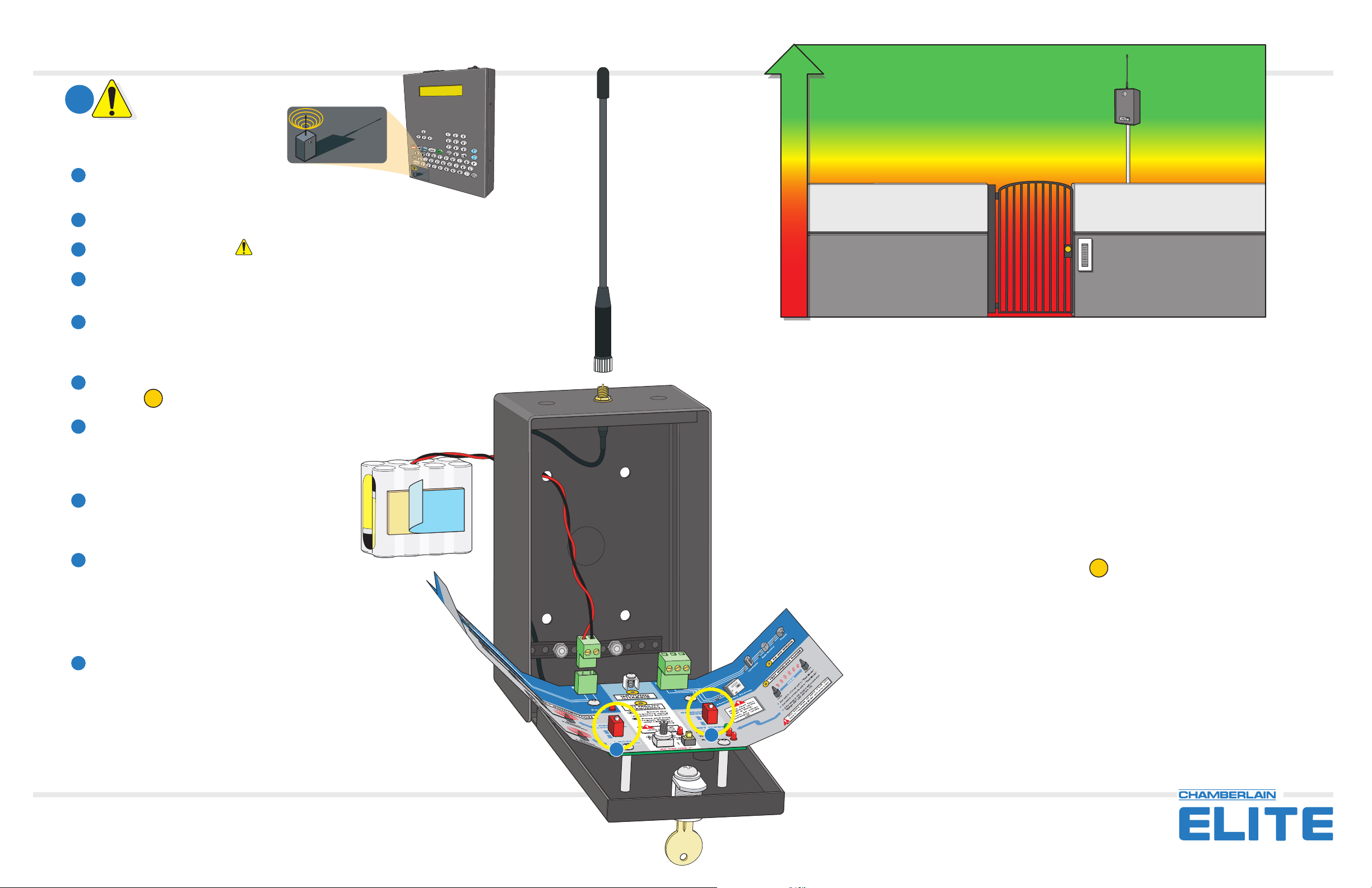
EWC485 Range Test
Stronger Signal
1
The Elite Processor MUST have this
sticker to use the wireless communicator.
Firmware version 6.11 or later.
2
Screw antennas on TIGHT.
Loose antennas will affect the signal strength!
Unlock the units and open doors.
3
Set both units to TEST MODE. ONLY test 2 units at a time, turn ALL other units OFF!
4
Set one unit to LOCAL connection and the other to REMOTE connection. The “LOCAL
5
connection” unit is near the telephone entry system.
6
Temporarily stick the supplied battery packs on the outside of each unit with the double stick
tape. Feed the wires through an existing hole on back of the unit. It is VERY important that BOTH
battery packs produce 12VDC, weak batteries will produce undependable test results.
Both units must be set to the same FACILITY FREQUENCY. If they are not the same,
7
follow Step 5 on the manual to set the frequencies on both units.
5
WIRELESS
communicator
Compatible
W
IR
E
com
L
E
m
S
u
S
n
i
c
C
a
o
t
o
m
r
p
a
t
ib
l
e
Less Interference
More Interference
Weak Signal
If a continuous tone is NOT heard during the range test:
Make sure the antennas are screwed on tight.
Connect the battery wires to the removable power connector. When BOTH
8
units have been powered up, a CONTINUOUS tone will be heard from both
units indicating strong signals are being transmitted
and received.
Close and lock the units placing the LOCAL unit in
9
its final position near the telephone entry system.
Recommend minimum 8 feet above ground.
Take the REMOTE unit to the desired remote access
10
Part Number 41A6082
point and place it in its final position.
A continuous tone should be heard indicating that the range is OK.
The units can now be permanently installed in their current
positions.
Use the supplied transformer for permanent power. Discard battery pack.
11
Set the units back to OPERATING MODE.
Try moving the remote unit 15-20 feet in several directions, away from metal surfaces or any obstructions.
Try moving the local unit 15-20 feet in several directions.
Try raising the units up, above the rooftops if necessary to clear any obstacles. The higher the units, the
less interference they will encounter. Keep antenna clear from metal surfaces or any obstructions that can
weaken the signal strength.
Test the battery packs with a voltmeter for 12VDC. Weak batteries will produce undependable test results.
Try changing the FACILITY FREQUENCY of the units. Follow Step 55 on the manual. Both units MUST be
set to the same frequency.
5
If a continuous tone is not achieved after all previous suggestions have been tried,
call for toll free technical support: 1-800-582-2806
4
5
114A2969
© 2004 The Chamberlain Group, Inc.
All Rights Reserved
®
™
845 Larch Avenue Elmhurst, Illinois 60126-1196
Page 2
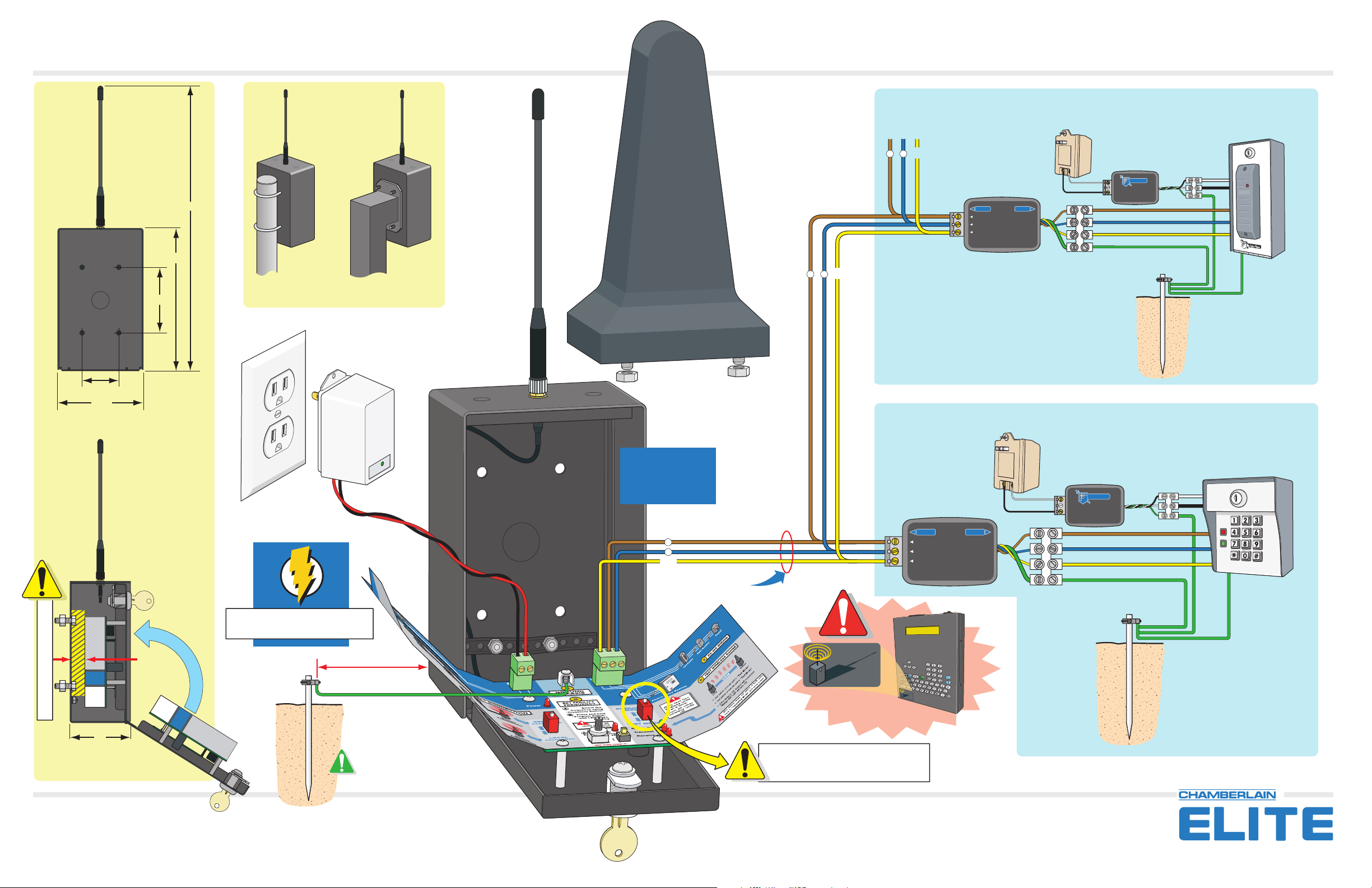
EWC485 Installation
14“
7“
Optional Antenna Cover
Protects against vandalism.
Part Number 41A6083
+
Gnd
–
To Next
RS485 Device
+
–
Gnd
Daisy Chain RS485 Devices Together
Use Separate Transformer
SURGE SUPPRESSOR
OUT IN
RS-485 (+)
RS-485 (-)
RS-485 GND
RS485
BROWN:
BLUE:
YELLOW:
GREEN:
12 Vac, 20VA
RS-485 (+)
RS-485 (-)
RS-485 GND
CHASSIS GND
POWER INPUT
SURGE SUPPRESSOR
Elite Entry Phone
eliteentryphone.comeliteentryphone.com
POWER INPUT
SURGE SUPPRESSOR
P/N: TAPISS
®
3.25“
1.8“
4.25“
Back View
Sample Mountings
Use Provided
Transformer
12 Vac, 20VA
Do not share
transformer with any
other devices.
BUILT-IN
SURGE PROTECTION
Suggestion:
Seal holes of box
with sealant when
finished wiring.
+
–
Gnd
RS485 Wire Run
22 AWG
Shielded Wire
Use Separate Transformer
12 Vac, 20VA
RS485
SURGE SUPPRESSOR
OUT IN
RS-485 (+)
RS-485 (-)
RS-485 GND
BROWN:
BLUE:
YELLOW:
GREEN:
RS-485 (+)
RS-485 (-)
RS-485 GND
CHASSIS GND
Wiring 1 RS485 Device
POWER INPUT
SURGE SUPPRESSOR
®
Elite Entry Phone
eliteentryphone.comeliteentryphone.com
POWER INPUT
SURGE SUPPRESSOR
P/N: TAPISS
12 AWG Wire
Mounting Bolt Clearance
3“
Side View
114A2969
Call for toll free technical support: 1-800-582-2806
.66“
3 Feet Max.
12 AWG Wire
The earth ground rod must be
located within 3 feet from the
wireless communicator.
Processor MUST have this sticker to use the wireless communicator.
Firmware version 6.11 or later.
Make sure the unit is set
to OPERATING MODE.
© 2004 The Chamberlain Group, Inc.
All Rights Reserved
WIRELESS
communicator
Compatible
12 AWG Wire
W
I
R
E
c
L
o
m
E
m
S
u
S
n
ic
C
a
o
t
m
or
p
a
t
i
bl
e
®
™
845 Larch Avenue Elmhurst, Illinois 60126-1196
 Loading...