

Page 1
TM
Single-Function
Remote Control Transmitter
Model 61LM
2-Channel
Remote Control Transmitter
Model 62LM
Multi-Function
Remote Control Transmitter
Model 63LM
Mini Multi-Function
Remote Control Transmitter
Model 64LM
F.C.C. rules prohibit adjustments to or modification of receiver and/or remote control transmitter circuitry except for changing the
code setting and replacing remote control transmitter battery. THERE ARE NO OTHER USER SERVICEABLE PARTS.
THIS DEVICE COMPLIES WITH F.C.C. RULES PART 15. Operation of this device is subject to the following two conditions: 1. This
device may not cause harmful interference. 2. This device must accept any interference that may be received, including interference
that may cause undesired operation.
Manufactured under 1 or more of the following U.S. patents: RE29,525; 4,037,201; 4,750,118; 4,806,930 — Other patents pending
WARNING
WARNING
CAUTION: ACTIVATE THE OPENER ONLY WHEN THE DOOR IS IN FULL VIEW, FREE OF OBSTRUCTION AND
PROPERLY ADJUSTED. NO ONE SHOULD ENTER OR LEAVE THE GARAGE WHILE DOOR IS IN MOTION. DO NOT
ALLOW CHILDREN TO OPERATE THE REMOTE(S) OR THE DOOR CONTROL BUTTONS. DO NOT ALLOW
CHILDREN TO PLAY NEAR THE DOOR.
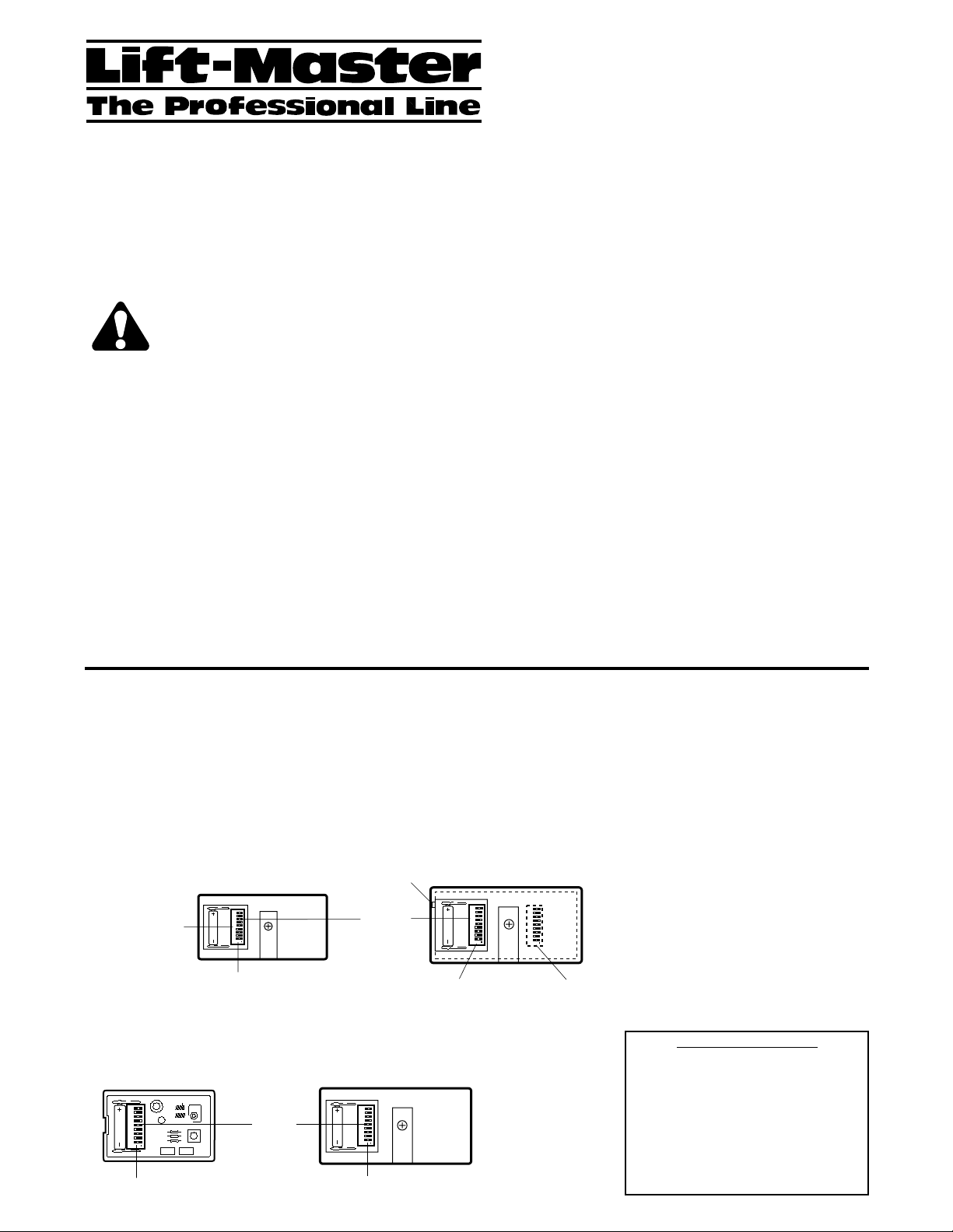
Match or change codes in new and original remote(s) as described and illustrated below. Side 2 explains how to set/change
receiver codes and how to use Multi- and 2-Function Remotes with other receivers.
The 2-Channel Remote Control has two push buttons (for
Channel 1 and Channel 2), each activated by its own set of
code switches. Refer to the illustration below. Channel 1 push
button has a smooth surface. One of the buttons can be used
to operate a garage door opener. The other button can
operate an entry way, light product or another door opener.
Access the code switches for Channel 1 push button
(recommended for a garage door opener) by sliding back the
battery compartment cover. To access the code switches for
Channel 2, remove the battery compartment cover and the
cover screw. Then depress the tab in edge of case
(alongside battery). The remote control case back will lift off.
Single-Function Remote Control: Slide the battery
compartment cover back to access code switches in the
NEW remote control. Locate code switches in original
remote control.
The Standard and Mini Multi-Function Remote Controls have
three push buttons. The large button is recommended for use with
a garage door opener. The other push buttons can be used to
operate another garage door opener and/or light control product.
Slide back the battery compartment cover to access the code
switches in the NEW standard Multi-Function Remote Control.
Remove the cover screw in the Mini Multi-Function Remote
Control. NOTE 1: In Multi-Function Remote Controls, only code
switches 2 through 9 must be set to matching positions. Code
switch #1 is neutral. Set it to any position. It will not affect the code.
NOTE 2: If Multi- and Single-Function Remote Controls will be
used to operate the same receiver, set code switch #1 in the
Single-Function Remote Control to match the Multi-Function
push button selected. (Refer to Illustration B on Side 2 for the
code positions that match the Multi-Function Remote Control
push buttons.
MA TCH/CHANGE THE CODE IN NEW AND EXISTING REMOTE CONTROL TRANSMITTER(S)
SET CODE SWITCHES IN ALL REMOTE CONTROL TRANSMITTERS T O MATCHING POSITIONS
If you want to keep the same code, proceed as follows (refer to the illustration of your Model Remote Control):
1. Locate code switches in original remote control(s), either by sliding the battery compartment cover back or by removing the cover
screw and turning case over (push button side up). When you set the case bottom aside, be careful to avoid moving circuit board
components.
2. Place remote controls side by side as shown. Set the code switches in the new remote control to the same positions as in the original
remote control. Use a screwdriver or pen to slide the switches. Refer to note above regarding code switch #1 in Multi-Function
Remote Controls.
REPLACEMENT PARTS
Visor clip 29C128
12V battery 10A14
Transmitter Case Only –
No Circuit Board:
Model 61LM 41A3565-6
Model 62LM 41A3608-3
Model 63LM 41A3580-3
Model 64LM 41A3568-8
2-Channel
Remote Control 62RGD
23456789
1
0
+
23456789
1
0
+
Channel 2
Code Switches (1-9)
Code switch #1 in a
Multi-Function
Remote Control
is neutral - set it
to any position.
Remote Control 61RGD
Match
Code
Switches
(1-9)
Code Switches (1-9)
Mini Multi-Function
Remote Control 64RGD
23456789
1
0
+
Code Switches (1-9)
Single-Function
23456789
1
0
+
Match
Code
Switches
(2-9)
Tab
Match
Code
Switches
(1-9)
Channel 1
Code Switches (1-9)
Multi-Function
Remote Control 63RGD
23456789
1
0
+
Code Switches (1-9)
Page 2
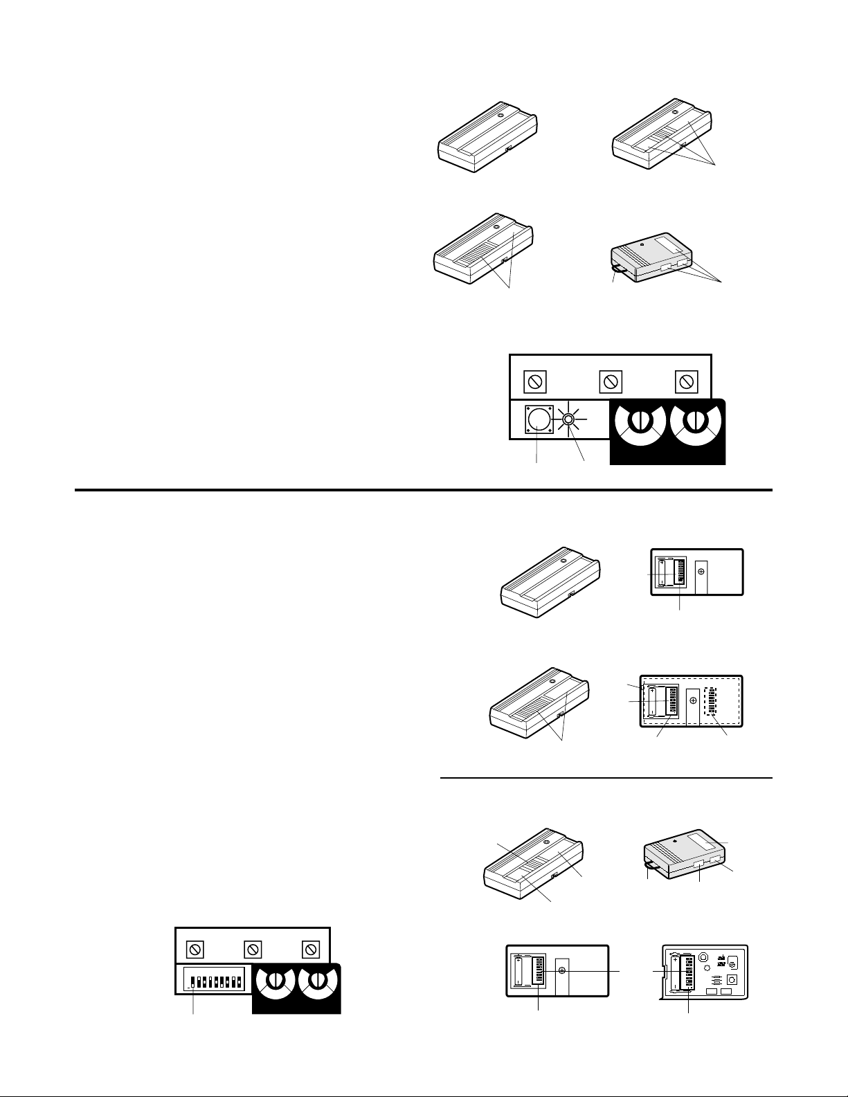
MATCH/CHANGE THE CODE IN RECEIVER
"Smart" Garage Door Openers with Receiver Code Button
Make sure all remote controls that will be used to operate the
same receiver are set to matching code switch positions as
described on Side 1.
FOR MULTI-FUNCTION REMOTE CONTROLS ONLY:
Decide which push button you want to use to operate the
receiver. The LARGE button is recommended for a garage
door opener.
FOR ALL MODEL REMOTE CONTROLS: Locate the
"Smart" code button on your garage door opener. (Illustration
A shows a representative garage door opener with the
receiver in the rear panel.)
YOU MAY WANT SOMEONE TO HELP AT THIS POINT!
1. Press and HOLD the selected remote control push button.
2. Then press the receiver "Smart" button on the back panel of
the opener. The adjacent indicator light will FLASH and the
door will begin to MOVE. Release the remote control push
button.
The opener will now operate when either the door control push
button or the transmitter push button is pressed.
NOTE: If the transmitter push button is not held down until the
receiver indicator light flashes, the receiver will not learn the
code.
To use the 2-Channel or Multi-Function Remote Control
with other "Smart" receivers: Select another remote control
push button to operate the device. All remote controls used to
operate receiver must be set to the same code (as described
on Side 1). Then repeat above procedure.
You can choose a different remote control push button to
operate each device.
Garage Door Openers and Light Controls with Receiver Code Switches
Make sure all remote controls that will be used to operate the
same receiver are set to matching code switch positions as
described on Side 1.
Locate the code switches on your garage door opener or light
control receiver. (Illustration B shows a representative garage
door opener with the receiver in the rear panel.)
FOR SINGLE AND 2-CHANNEL REMOTE CONTROLS:
Hold remote control alongside receiver. Set receiver code
switches 1 through 9 to match the remote control positions.
The code switches for the remaining channel in your 2Channel Remote Control can be set to operate another garage
door opener, an entry way or light control. Make sure the
receiver code switches are set to the same positions.
FOR MULTI-FUNCTION REMOTE CONTROL: Decide which
of the three push buttons you want to use to operate the
receiver. The LARGE button is recommended for a garage
door opener.
Set RECEIVER code switch #1 to match the position of the
remote control push button selected. Refer to Illustration B.
Then set receiver code switches 2 through 9 to match remote
control switches 2 through 9.
To use the Multi-Function Remote Control with another
garage door opener or light control: Set receiver code
switch #1 to match the position of another remote control push
button. Then set remaining code switches to match remote
control(s) code switches 2 through 9.
© 1996, The Chamberlain Group, Inc.
114A2029 All Rights Reserved Printed in Mexico
Model 64RGD
Mini Multi-Function
Remote Control
Push
Button (0)
Push
Button (+)
Push
Button (-)
Match
Code
Switches
(2-9)
Push
Button
(0)
Push
Button
(-)
Key Ring
Holder
Push
Button
(+)
1
23456789
+
0
Code Switches (1-9)
1
23456789
+
0
Code Switches (1-9)
Model 63RGD
Multi-Function
Remote Control
B
B
A
Single-Function Remote Control
Model 61RGD
Model 62RGD
2-Channel Remote Control
Select a
Push Button
"SMART" GARAGE DOOR OPENER
RED
"Smart"
Button
Model 63RGD
Multi-Function Remote Control
Model 64RGD
Mini Multi-Function Remote Control
Key Ring
Holder
WHT BLK
Indicator
H
I
G
H
N
O
FORCE
H
L
I
O
G
W
H
L
N
A
M
R
UP
O
R
DOWN
FORCE
A
M
Light
Select a
Push Button
Select a
Push Button
L
O
W
L
Single-Function Remote Control
Select Remote
Control Push Button
Slide receiver code switch #1 to position that
matches selected transmitter push button (+, 0 or -).
With code switch #1 set in the (-) position, receiver
will operate with transmitters' large push button.
RECEIVER
RED
23456789
1
+
0
H
I
G
H
N
O
FORCE
H
L
I
O
G
W
H
L
A
M
R
UP
WHT BLK
L
O
W
L
N
A
O
M
R
DOWN
FORCE
Model 61RGD
Match
Code
Switches
(1-9)
Code Switches (1-9)
Model 62RGD
2-Channel Remote Control
Tab
Match
Code
23456789
1
Switches
(1-9)
Channel 1
Code Switches
(1-9)
+
0
23456789
1
0
+
23456789
1
0
+
Channel 2
Code Switches
(1-9)
Page 3

TM
Transmisor de control
remoto unifuncional
Modelo 61LM
Transmisor de control
remoto de dos canales
Modelo 62LM
Transmisor de control
remoto multifuncional
Modelo 63LM
Mini-transmisor de control
remoto multifuncional
Modelo 64LM
Las reglas de la F.C.C. (Comisión Federal de Comunicaciones) prohíbe ajustes o modificaciones a los circuitos del receptor y/o transmisor de control remoto
salvo para cambiar la selección de código y reemplazar la batería del transmisor de control remoto.
NO HAY OTRAS PIEZAS QUE PUEDA REPARAR EL USUARIO.
ESTE DISPOSITIVO CUMPLE CON LAS REGLAS DE LA F.C.C. PARTE 15. La operación de este dispositivo está sujeta a las dos siguientes condiciones: 1.
Este dispositivo puede causar interferencia dañina. 2. Este dispositivo debe aceptar cualquier interferencia que pueda recibirse, incluyendo la interferencia que
puede causar la operación no deseada.
Fabricado bajo 1 o más de las siguientes patentes de los EE.UU.: RE29,525; 4,037,201; 4,750,118; 4,806,930 — Otras patentes pendientes
WARNING
WARNING
PRECAUCION: ACTIVAR EL ABRIDOR SOLO CUANDO LA PUERTA ESTE A PLENA VISTA, LIBRE DE
OBSTRUCCIONES Y DEBIDAMENTE AJUSTADA. NADIE DEBE ENTRAR NI SALIR DEL GARAJE MIENTRAS LA PUERTA
ESTE EN MOVIMIENTO. NO PERMITIR A LOS NIÑOS OPERAR LOS CONTROLES REMOTOS NI LOS BOTONES DE
CONTROL DE LA PUERTA. NO PERMITIR A LOS NIÑOS JUGAR CERCA DE LA PUERTA.
Hacer concordar o cambiar los códigos de los controles remotos nuevos y originales según se describe e ilustra a continuación. El
lado 2 explica cómo ajustar/cambiar los códigos de receptor y cómo utilizar los controles remotos multifuncionales y de 2 canales
con otros receptores.
El Control remoto de 2 canales tiene dos botones pulsadores (para
el Canal 1 y el Canal 2), cada uno está activado por su propio juego
de interruptores de código. Consultar la ilustración a continuación. El
botón pulsador del Canal 1 tiene una superficie lisa. Uno de los
botones puede usarse para operar un abrepuerta de garaje. El otro
botón puede operar un abrepuerta de entrada, una luz u otra puerta.
Puede accederse a los interruptores de código para el botón
pulsador del Canal 1 (recomendado para un abrepuerta de garaje)
deslizando hacia atrás la tapa del compartimiento de batería. Para
acceder a los interruptores de código para el Canal 2, retirar la tapa
del compartimiento de la batería y el tornillo de la tapa. Luego
presionar la lengüeta en el borde de la caja (en el costado de la
batería). La parte posterior de la caja del control remoto se levantará.
Control remoto unifuncional: Deslizar la tapa del compartimiento
de la batería para acceder a los interruptores de código en el control
remoto NUEVO. Localizar los interruptores de código en el control
remoto original.
Los Controles remotos estándar y mini multifuncionales tienen
tres botones pulsadores. El botón grande se recomienda para usarse
con un abrepuerta de garaje. Los otros botones pulsadores pueden
usarse para operar otro abrepuerta de garaje y/o controlar alguna luz.
Deslizar la tapa del compartimiento de la batería hacia atrás para
acceder a los interruptores de código en el NUEVO Control remoto
multifuncional estándar. Retire el tornillo de la tapa en el Mini-control
remoto multifuncional. NOTA 1: En los Controles remotos
multifuncionales, sólo deben ajustarse los interruptores del 2 hasta el
9 en las posiciones concordantes. El interruptor #1 es neutro. Se fija
en cualquier posición. No afecta el código.
NOTA 2: Si se van a usar Controles remotos multifuncionales o
unifuncionales para operar el mismo receptor, ajustar el interruptor de
código #1 en el Control remoto unifuncional para que concuerde con
el botón pulsador multifuncional seleccionado. (Consultar la
ilustración B en el lado 2 para las posiciones de código que
concuerden con los botones pulsadores del Control remoto
multifuncional.
PARA HACER CONCORDAR/CAMBIAR EL CODIGO EN TRANSMISORES DE CONTROL REMOTO
NUEVOS Y EXISTENTES AJUSTAR LOS INTERRUPTORES DE CODIGO EN TODOS LOS TRANSMISORES
DE CONTROL REMOTO EN LAS POSICIONES CONCORDANTES
Si se desea mantener el mismo código, proceder como sigue (consultar la ilustración del Control remoto modelo):
1. Localizar los interruptores de código en los controles remotos originales, deslizando la tapa del compartimiento de batería hacia atrás o
retirando el tornillo de la tapa y poniendo la caja boca abajo (con el lado del botón pulsador hacia arriba). Cuando se deje de lado la parte
inferior de la caja, tener cuidado de evitar mover los componentes de la placa de circuitos.
2. Colocar los controles remotos uno al lado del otro como se indica. Ajustar los interruptores de código en el nuevo control remoto en las
mismas posiciones que el control remoto original. Usar un destornillador o lápiz para deslizar los interruptores. Consultar la nota anterior
con respecto al interruptor de código #1 en los Controles remotos multifuncionales.
PIEZAS DE REPUESTO
Sujetador para visera 29C128
Batería de 12V 10A14
Caja de control remoto –
sin placa de circuitos:
Modelo 61LM 41A3565-6
Modelo 62LM 41A3608-3
Modelo 63LM 41A3580-3
Modelo 64LM 41A3568-8
Control remoto de
2 canales 62LM
23456789
1
0
+
23456789
1
0
+
Interruptores de
código del Canal 2 (1-9)
El interruptor de código #1
en un Control remoto
multifuncional es neutro,
puede ajustarse
en cualquier posición.
Interruptores
de código
concordantes
(1-9)
Mini-control remoto
multifuncional 64LM
23456789
1
0
+
Control remoto
unifuncional 61LM
23456789
1
0
+
Interruptores de código (1-9)
Interruptores
de código
concordantes
(2-9)
Interruptores de código (1-9)Interruptores de código (1-9)
Lengüeta
Interruptores
de código
concordantes
(1-9)
Interruptores de
código del Canal 1 (1-9)
Control remoto
multifuncional 63LM
23456789
1
0
+
Page 4

© 1996, The Chamberlain Group, Inc.
114A2029 Todos los derechos reservados Impreso en México
1
23456789
+
0
Deslizar el interruptor #1 de código de receptor a la posición que
concuerda con el botón pulsador del transmisor seleccionado (+, 0 ó -).
Con el interruptor de código #1 fijo en la posición (-), el receptor
operará con el botón pulsador grande del transmisor.
RECEPTOR
H
I
G
H
L
O
W
N
O
R
M
A
L
H
I
G
H
L
O
W
N
O
R
M
A
L
UP
FORCE
DOWN
FORCE
ROJO
BCO NEG
PARA HACER CONCORDAR/CAMBIAR EL CODIGO DEL RECEPTOR
"Abrepuertas de garaje "inteligentes" con botón de código receptor
Asegurarse de que todos los controles remotos a usarse para
operar el mismo receptor estén fijados para concordar con las
posiciones de los interruptores de código como se describe en el
lado 1.
PARA CONTROLES REMOTOS MULTIFUNCIONALES
SOLAMENTE: Decidir cuál botón pulsador se desea usar para
operar el receptor. Se recomienda el botón GRANDE para un
abrepuerta de garaje.
PARA TODOS LOS MODELOS DE CONTROLES REMOTOS: L
Localizar el botón de código “inteligente” en el abrepuerta de
garaje. (La ilustración A muestra un abrepuerta de garaje
representativo con el receptor en el panel posterior.)
¡PUEDE SER CONVENIENTE PEDIR LA AYUDA A OTRA
PERSONA EN ESTE MOMENTO!
1. Presionar y MANTENER PRESIONADO el botón pulsador de
control remoto seleccionado.
2. Luego presionar el botón “inteligente” del receptor en el panel
posterior del abrepuerta. La luz indicadora adyacente
DESTELLARA y la puerta comenzará a MOVERSE. Soltar el
botón pulsador del control remoto.
El abrepuerta operará ahora cuando se presione el botón pulsador
de control de la puerta o el botón pulsador del transmisor.
NOTA: Si no se mantiene presionado el botón pulsador del
transmisor hasta que destelle la luz indicadora del receptor, el
receptor no memorizará el código.
Para usar el Control remoto de 2 canales o el multifuncional
con otros receptores "inteligentes": Seleccionar otro botón
pulsador del control remoto para operar el dispositivo. Todos los
controles remotos usados para operar el receptor deben ajustarse
en el mismo código (como se describe en el lado 1). Luego repetir
el procedimiento anterior.
Se puede escoger un botón pulsador de control remoto distinto
para operar cada dispositivo.
Abrepuertas de garaje y controles de luz con interruptores de código de receptor
Asegurarse de que todos los controles remotos que se usen para
operar el mismo receptor estén fijos en las posiciones de
interruptor según el código concordante descrito en el lado 1.
Localice los interruptores de código en el abrepuerta de garaje o el
receptor de control de luz. (la ilustración B muestra un abrepuerta
de garaje representativo con el receptor en el panel posterior.)
PARA CONTROLES REMOTOS DE 1 Y 2 CANALES: Sostenga el
receptor de control remoto junto al receptor. Fije los interruptores
de código del receptor del 1 al 9 para que concuerden con las
posiciones del control remoto.
Los interruptores de código para el canal restante en el Control
remoto de 2 canales pueden ajustarse para operar otro abrepuerta
de garage, una entrada o controlar luces. Asegurarse de que los
interruptores de código del receptor estén fijos en las mismas
posiciones.
PARA EL CONTROL REMOTO MULTIFUNCIONAL: Decidir cuál
de los tres botones pulsadores quiere usar para operar el receptor.
El botón GRANDE se recomienda para un abrepuerta de garage.
Ajustar el interruptor de código de RECEPTOR #1 para que
concuerde la posición del botón pulsador de control remoto
seleccionado. Consultar la ilustración B. Entonces fije los
interruptores de código de receptor del 2 al 9 para que concuerden
con los interruptores del 2 al 9 del control remoto.
Para usar el control remoto multifuncional con otro
abrepuerta de garaje o control de luz: Ajustar el interruptor de
código de receptor #1 para que concuerde la posición con otro
botón pulsador de control remoto. Entonces ajustar los
interruptores de código restantes para concordar los interruptores
de código de control remoto del 2 al 9.
B
B
A
Modelo 61LM
Control remoto unifuncional
Modelo 62LM
Control remoto de 2 canales
Seleccione un
botón pulsador
ABREPUERTA DE GARAJE "INTELIGENTE"
ROJO
Botón
"Inteligente"
Modelo 63LM
Control remoto multifuncional
Seleccione un
botón pulsador
Modelo 64LM
Mini-control remoto multifuncional
L
O
W
L
A
Seleccione un
botón pulsador
H
I
G
H
L
N
A
O
M
R
DOWN
FORCE
Gancho para
llavero
BCO NEG
H
I
G
H
N
O
R
UP
FORCE
M
Luz Indicadora
L
O
W
Seleccione el botón
pulsador de control remoto
Botón
Modelo 63LM
Control remoto
multifuncional
pulsador (+)
pulsador (0)
Modelo 61LM
Control remoto unifuncional
Interruptores
de código
concordantes
(1-9)
Interruptores de código (1-9)
Modelo 62LM
Control remoto de 2 canales
Lengüeta
Interruptores
de código
concordantes
(1-9)
Interruptores de
código de Canal 1
(1-9)
Modelo 64LM
Mini-control remoto
multifuncional
Botón
pulsador (-)
Botón
Gancho para
llavero
23456789
1
0
+
23456789
23456789
1
1
0
+
0
+
Interruptores de
código de Canal 2
Botón
pulsador
(0)
(1-9)
Botón
pulsador
(-)
Botón
pulsador
(+)
Interruptores de código (1-9)
23456789
1
0
+
Interruptores
de código
concordantes
(2-9)
Interruptores de código (1-9)
23456789
1
0
+
 Loading...