

Page 1
To prevent possible SERIOUS INJURY or DEATH from a moving
gate or garage door:
• ALWAYS keep remote controls out of reach of children. NEVER
permit children to operate, or play with remote control
remote controls.
• Activate gate or door ONLY when it can be seen clearly, is
properly adjusted, and there are no obstructions to door travel.
• ALWAYS keep gate or garage door in sight until completely
closed. NEVER permit anyone to cross path of moving gate
or door.
WARNING
Figure 1
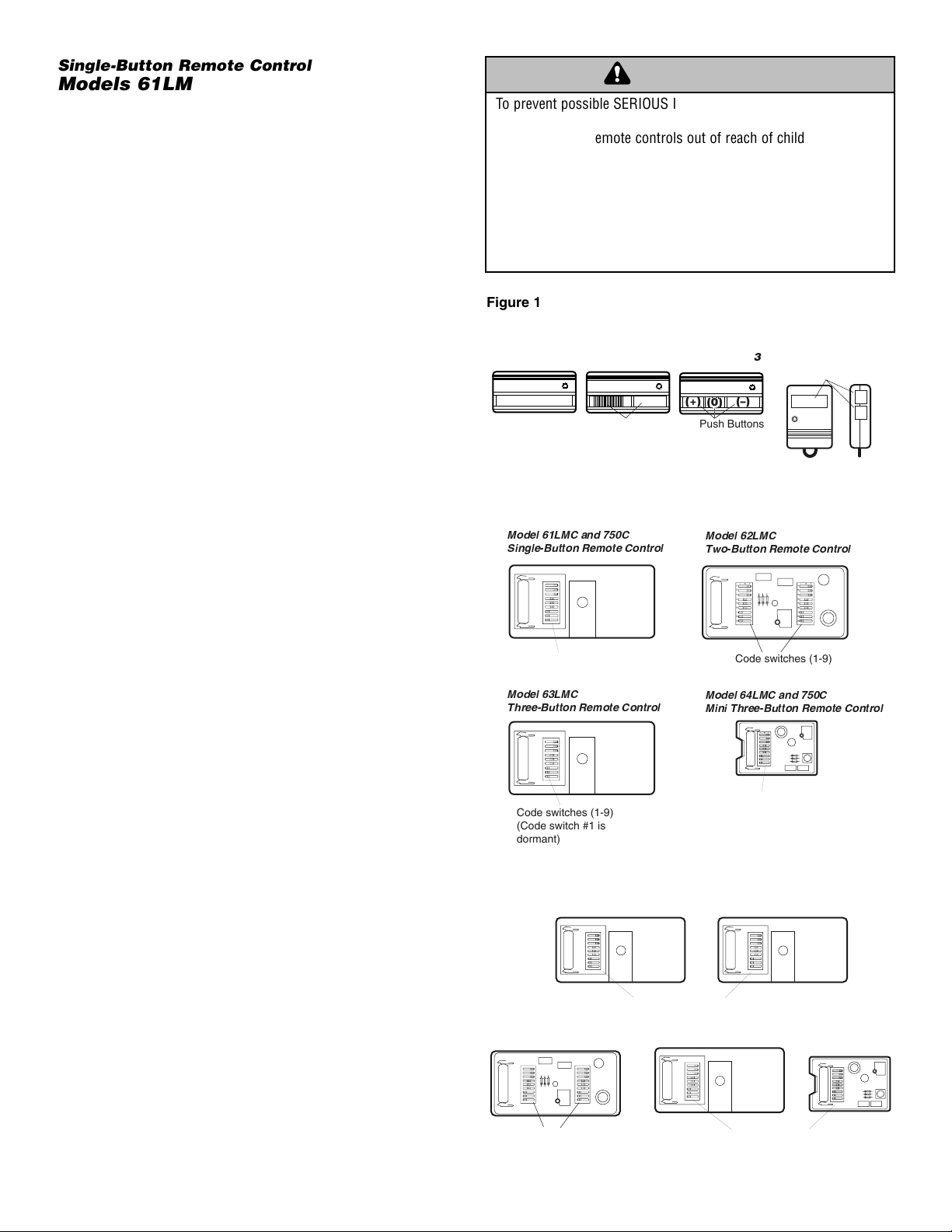
Single-Button Remote Control
Models 61LMC and 750C
Two-Button Remote Control
Model 62LMC
Three-Button Remote Control
Model 63LMC
Three-Button Mini Remote Control
Models 64LMC and 756C
Locating Your Code Switches
• Single-Button Remote Control:
Slide the battery compartment cover back to access the code
switches in the remote control (Figure 2).
• Two-Button Remote Control:
The two push buttons (button 1 and button 2), are activated by
their own set of code switches. One of the buttons can be
used to operate a garage door opener. The other button can
operate an entry way, light product or another door opener.
Access the code switches for button 1 (smooth button) by
sliding back the battery compartment cover. To access the
code switches for button 2 (ribbed button), remove the battery
compartment cover and the cover screw. Then depress the
tab in the edge of the case (alongside the battery). The
remote control case back will lift off (Figure 2).
• Three-Button Remote Control:
The large button is recommended for use with a garage door
opener. The other push buttons can be used to operate
another garage door opener and/or light control product.
Slide the battery compartment cover to access the code
switches in the three-button remote control (Figure 2).
• Mini Three-Button Remote Control:
The large top button is recommended for use with a garage
door opener and/or light control product. The other push
buttons can be used to operate another garage door opener
and/or light control product.
Access the code switches by turning the remote over and
removing the back of the case. Be careful to avoid moving
circuit board components (Figure 2).
To match or change the code in the
remote control
Locate the code switches in both the new and the original remote
control, either by removing the case screw and cover or by
sliding the battery compartment cover back. Place
remote controls side by side as shown (Figure 3) and set
switches in all remote controls to matching positions (+,0,-). Use
a pen or screwdriver to slide the code switches.
NOTE: Code switch #1 on the three-button remote control is
dormant, when used with a single-button remote control. Set
code switch #1, in the single-button remote control, to match the
push button selected on the three-button remote control
(Figure 1).
Figure 2
Figure 3
1
WARNING
61 Series
750 Series
62 Series
Push Buttons
Model 61LMC and 750C
Single-Button Remote Control
Model 63
(+)
(–)
(0)
Push Buttons
Model 62LMC
Two-Button Remote Control
64 Series
756 Series
Push Buttons
(–)
Front View
Side View
(+)
(0)
+0–
1 2 3 4 5 6 7 8 9
Code switches (1-9)
Model 63LMC
Three-Button Remote Control
+0–
1 2 3 4 5 6 7 8 9
Code switches (1-9)
(Code switch #1 is
dormant)
+0–
1 2 3 4 5 6 7 8 9
+0–
1 2 3 4 5 6 7 8 9
+0–
1 2 3 4 5 6 7 8 9
+0–
1 2 3 4 5 6 7 8 9
Code switches (1-9)
Model 64LMC and 750C
Mini Three-Button Remote Control
Code switches (1-9)
(Code switch #1 is
dormant)
+0–
1 2 3 4 5 6 7 8 9
Match code switches (1-9)
between old remote control and
new remote control
+0–
1 2 3 4 5 6 7 8 9
+0–
1 2 3 4 5 6 7 8 9
+0–
+0–
Match code switches (1-9)
between old remote control and
new remote control
Match code switches (2-9)
between old remote control and
new remote control
Page 2
© 2006 The Chamberlain Group, Inc.
114A1356F All Rights Reserved
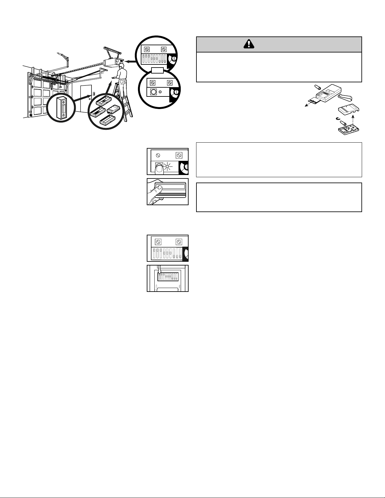
Programming the Opener
If your unit has a “Learn” button:
1. Press and release the “learn” button
located on the back panel of the motor unit.
The learn indicator light will glow steadily for
30 seconds.
2. Within the 30 second window, press and hold
the button on the hand-held remote.
3. The unit will either activate or the opener light
bulb will blink signifying it has learned the
code.
If your unit has code switches:
1. Using a step ladder climb up to the back
of your motor unit. Check the code switch
settings on the back of the motor unit.
2. Use a pen or screw driver to set the code
switches on the back of the remote control to
match the code switches on the back of
the motor unit.
3. Once the code switches have been set push
the remote control button to activate
your unit.
N
Replacing the Remote Control Battery
Locate the battery by either removing the
case screw and the cover or by sliding
the battery compartment cover.
Dispose of old batteries properly.
To prevent possible SERIOUS INJURY or DEATH:
• NEVER allow small children near batteries.
• If battery is swallowed, immediately notify doctor.
WARNING
NOTICE: To comply with FCC and or Industry Canada (IC) rules, adjustment or modifications of this
receiver and/or remote control are prohibited, except for changing the code setting or replacing the
battery. THERE ARE NO OTHER USER SERVICEABLE PARTS.
Tested to Comply with FCC Standards FOR HOME OR OFFICE USE. Operation is subject to the
following two conditions: (1) this device may not cause harmful interference, and (2) this device
must accept any interference received, including interference that may cause undesired operation.
Replacement Parts
Visor clip . . . . . . . . . . . . . . . . . . . . . . . . . . . . . . . . . .29C128
12V Battery . . . . . . . . . . . . . . . . . . . . . . . . . . . . . . . . .10A14
RED-1
+
0
–
123456789
OR
RED-1
WHT-2
WHT-2
WARNING
H
I
G
H
N
O
M
R
H
I
G
H
N
O
M
R
H
I
G
H
N
O
R
+
0
–
1 2 3 4 5 6 7 8 9
+
0
–
123456789
H
I
G
H
Page 3

s
Télécommande à un bouton
Modéle 61LMC et 750C
Télécommande à deux boutons
Modéle 62LMC
Télécommande à trois boutons
Modéle 63LMC
Petit Télécommande à trois boutons
Modéle 64LMC et 756C
Emplacement de vos commutateurs de codes
• Télécommande à un bouton :
Glisser le dos du couvercle du compartiment à piles afin
d’accéder aux commutateurs de codes dans le télécommande
(Figure 2).
• Télécommande à deux boutons :
Le deux boutons-poussoirs (au bouton 1 et au bouton 2), chacun
d’entre eux activés par son propre ensemble de commutateurs de
codes. L’un des boutons peut servir au fonctionnement de
l’ouvre-porte de garage et l’autre peut activer une entrée, une lumière
ou un autre ouvre-porte.
Accéder aux commutateurs de codes correspondant au bouton 1
(bouton lisse) en glissant le couvercle du compartiment à piles vers
l’arrière. Afin d’accéder aux commutateurs de codes correspondant au
bouton 2 (bouton nervuré), retirer le couvercle du compartiment à
piles ainsi que la vis. Enfoncer ensuite la languette dans l’extrémité du
boîtier (le long du bord de la pile). Le dos du boîtier de la
télécommande se soulève (Figure 2).
• Telécommande à trois bouton :
Il est recommandé d’utiliser le gros bouton avec un ouvre-porte de
garage. Les autres boutons-poussoirs peuvent servir au
fonctionnement d’un autre ouvre-porte de garage et/ou d’une
commande d’éclairage.
Glisser le couvercle du compartiment à piles afin d’accéder aux
commutateurs de codes situés dans le télécommande à trois
boutons (Figure 2).
• Petit télécommande à trois boutons :
Il est recommandé d’utiliser le gros bouton supérieur avec un
ouvre-porte de garage ou une commande d’éclairage. Utiliser les
autres boutons-poussoirs pour le fonctionnement d’un autre ouvreporte de garage ou commande d’éclairage.
Accéder aux commutateurs de codes en retournant la télécommande
et en retirant le dos du boîtier. S’assurer de ne pas déplacer les
composants de la carte de circuit (Figure 2).
Pour faire correspondre les codes de le
télécommande
Repérer la position des commutateurs de codes dans le nouveau et
l’ancien télécommande, soit en retirant la vis et le couvercle du boîtier ou
en faisant glisser le couvercle du compartiment à piles. Disposer les
télécommandes côte à côte (Figure 3), puis faire correspondre les
positions des commutateurs de codes du nouvel télécommande avec
celles des commutateurs de codes de l’ancien télécommande (+, 0, -).
Utiliser un stylo ou un tournevis pour changer la position des
commutateurs de codes.
REMARQUE : Le commutateur de codes n° 1 de le télécommande à
trois bouton est inactif lorsqu’il est utilisé avec un télécommande à
un bouton. Faire correspondre la position du commutateur de codes
n° 1 de le télécommande à un bouton à celle du bouton-poussoir
sélectionné de le télécommande à trois boutons (Figure 1).
+0–
1 2 3 4 5 6 7 8 9
+0–
1 2 3 4 5 6 7 8 9
Faire correspondre
commutateurs de codes (1-9)
de l'ancien et du nouvel télécommande
Faire correspondre
commutateurs de codes (1-9)
de l'ancien et du nouvel télécommande
Faire correspondre
commutateurs de codes (2-9)
de l'ancien et du nouvel télécommande
+0–
1 2 3 4 5 6 7 8 9
+0–
1 2 3 4 5 6 7 8 9
+0–
+0–
1 2 3 4 5 6 7 8 9
1
Afin d’éliminer les risques de BLESSURES GRAVES ou de MORT
découlant de l’actionnement d’une clôture ou d’une porte de garage :
• TOUJOURS garder les télécommandes hors de la portée des enfants. NE
JAMAIS laisser un enfant manipuler une télécommande ni jouer avec
elle.
• Actionner la clôture ou la porte UNIQUEMENT lorsqu’elle est clairement
visible, correctement ajustée et que le mécanisme est libre de toute
entrave.
• TOUJOURS garder la clôture ou la porte de garage en vue jusqu’à sa
fermeture complète. NE permettez à quiconque de passer lorsqu’une
clôture ou une porte est en mouvement.
WARNING
CAUTION
WARNING
WARNING
AVERTISSEMENT AVERTISSEMENT
Figure 1
Figure 2
Figure 3
AVERTISSEMENT
Modéle 61
Modéle 750
Modéle 61LMC et 750C
Télécommande à un bouton
+0–
1 2 3 4 5 6 7 8 9
Commutateurs de code (1-9)
Modéle 63LMC
Télécommande à trois boutons
+0–
1 2 3 4 5 6 7 8 9
Commutateurs de code (1-9)
(Le commutateur de codes
nº 1 est inactif)
Modéle 62
Boutons-poussoirs
Modéle 63
(+)
Boutons-poussoirs
(–)
(0)
Vue de face
Modéle 62LMC
Télécommande à deux boutons
+0–
1 2 3 4 5 6 7 8 9
Commutateurs de code (1-9)
Modéle 64LMC et 750C
Petit télécommande à trois bouton
+0–
Commutateurs de code (1-9)
(Le commutateur de codes
nº 1 est inactif)
Modéle 64
Modéle 756
Boutons-poussoirs
(–)
1 2 3 4 5 6 7 8 9
(+)
(0)
Vue latérale
+0–
Page 4

© 2006 The Chamberlain Group, Inc.
114A1356F Tous droits réservés
Programmation de l’ouvre-porte
Si l’unité comporte un bouton ‹‹ learn ›› :
1. Enforncer et relâcher le boutron learn sur le
moteur. Le témoin lumineux learn s’allumera en
continu pendant 30 secondes.
2. Dan un délai de 30 secondes, enforncer et tenir
le bouton de la télécommande.
3. Relâchere le bouton lorsque l’eclairage du
moteur clignote. Il a appris le code. Si les
ampoules ne sont pas posées, deux clics se
feront entendre.
Si l’unité comporte des commutateurs de
codes :
1. À l’aide d’un escabeau, accéder à l’arrière du
moteur. Vérifier la position des commutateurs de
codes situés à l’arrière du moteur.
2. Utiliser un stylo ou un tournevis pour modifier les
positions des commutateurs de codes afin de
les faire correspondre à celles des
commutateurs situés à l’arrière du moteur.
3. Une fois les positions des commutateurs de
codes établies, appuyer sur le bouton de le
télécommande afin d’activer l’unité.
N
Les piles de télécommande
Insérer la pile après avoir retiré la vis et le
couvercle du boîter ou glissé le couvercle
du compartiment à piles.
Se débarrasser des vieilles piles
convenablement.
List de pièces
Agrafe pare-soleil . . . . . . . . . . . . . . . . . . . . . . . . . . . . . .29C128
Pile de 12V . . . . . . . . . . . . . . . . . . . . . . . . . . . . . . . . . . . .10A14
Pour prévenir d’’eventuelles BLESSURES GRAVES ou la MORT :
• NE JAMAIS laisser de petits enfants à proximité des piles.
• Aviser immédiatement un médecin en cas d’ingestion de la pile.
WARNING
CAUTION
WARNING
WARNING
AVERTISSEMENT AVERTISSEMENT
AVIS : Les règles de la FCC ou d’Industrie Canada (IC), ou les deux, interdisent tout ajustement ou
toute modification de ce récepteur et/ou de cet télécommande, sauf pour modifier le code ou pour
remplacer la pile. IL N’EXISTE AUCUNE AUTRE PIÈCE SUSCEPTIBLE D’ÊTRE ENTRETENUE PAR
L’UTILISATEUR.
Vérifié pour conformité avec les normes de la FCC POUR UTILISATION À LA MAISON OU AU
BUREAU. L’utilisation est sujette aux deux conditions ci-après : (1) ce dispositif ne peut causer des
interférences nuisibles, et (2) ce dispositif doit accepter toute interférence reçue, y compris une
interférence pouvant causer un fonctionnement non désiré.
RED-1
+
0
–
123456789
OU
RED-1
WHT-2
WHT-2
AVERTISSEMENT
H
I
G
H
N
O
M
R
H
I
G
H
N
O
M
R
+
0
–
1 2 3 4 5 6 7 8 9
+
0
–
123456789
H
I
G
H
N
O
R
H
I
G
H
 Loading...