

Page 1
Lift-Master
The Professional Line
®
UNIVERSAL RADIO CONTROL
Model 500LM Model 500-1LM Model 500-2LM
Receiver Only (With 1 Transmitter) (With 2 Transmitters)
F.C.C . rules prohibit adjustments to or modification of receiver and/or transmitter circuitry expect for changing the code setting and replacing the transmitter
battery. THERE ARE NO USER SERVICEABLE PARTS.
The receiver may be installed in one of two ways: 1. attached to an inside wall of the garage with connecting bell wire (not supplied).
2. mounted directly on the door opener with clips provided.
When installing two or more receivers in garage, position them at least 10 feet apart to prevent electronic interference.
NOTE: Models 500-1LM and 500-2LM are factory pre-set with matching receiver and transmitter codes.
CAUTION: Do not attempt to open the receiver back panel. THERE ARE NO USER SERVICEABLE PARTS.
MANUFACTURED UNDER 1 OR MORE OF THE FOLLOWING U.S. PATENTS: RE29,525; 4,037,201; 4,750,118; 4,806,930
MODEL 85 TRANSFORMER MAY BE REQUIRED IF YOUR GARAGE DOOR OPENER IS
A BRAND OTHER THAN LIFT-MASTER, CHAMBERLAIN OR SEARS.
INSTALL THE RECEIVER OUT OF THE REACH OF CHILDREN. DO NOT ALLOW CHILDREN TO OPERATE
RECEIVER OR TRANSMITTER(S). SERIOUS PERSONAL INJURY FROM A CLOSING GARAGE DOOR MAY
RESULT FROM MISUSE OF THE OPENER.
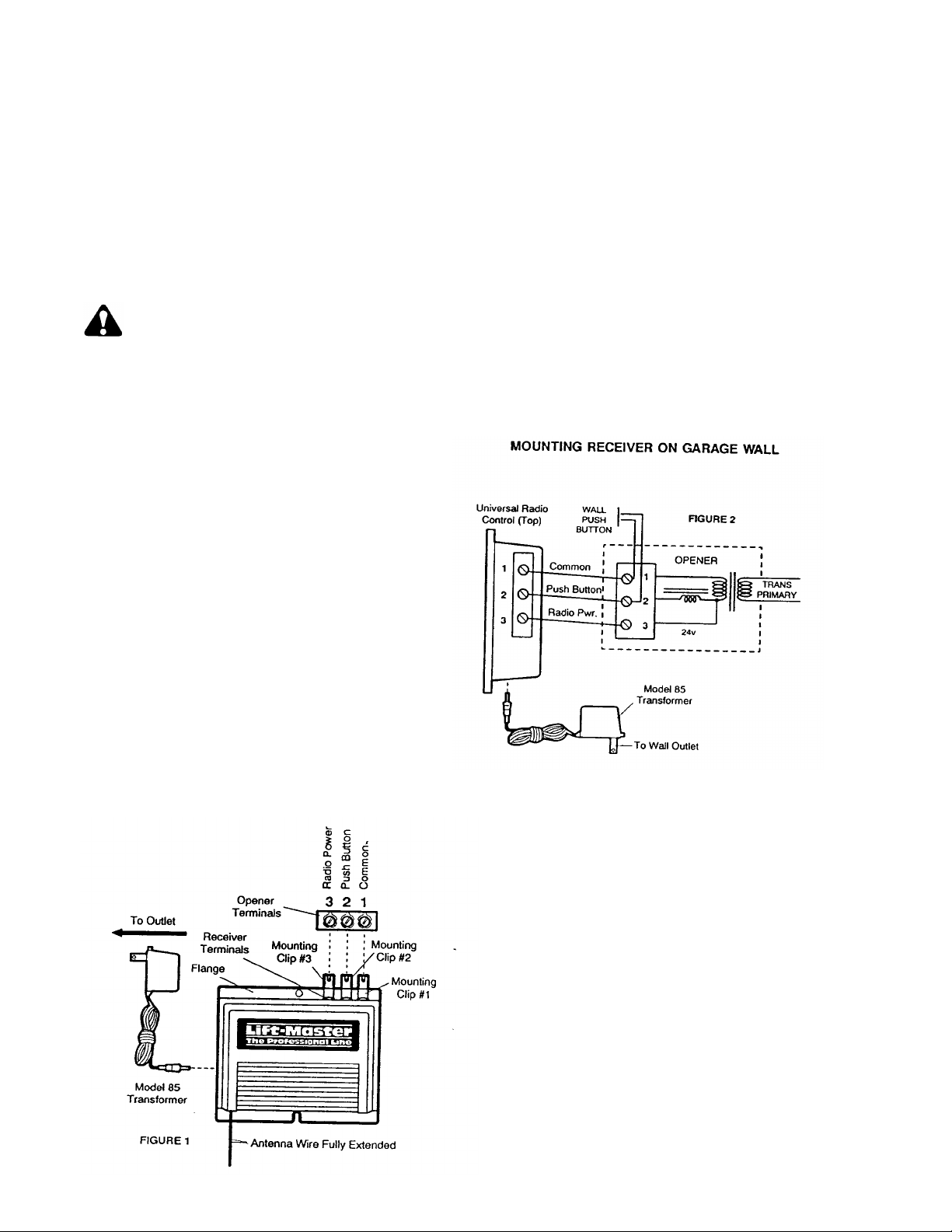
Fully extend antenna wire below bottom of case shown.
MOUNTING RECEIVER ON OPENER
Loosen the three terminal screws on either side of the receiver
(labeled 1,2, and 3). Insert one end of a mounting clip under
each terminal. Make sure clips are positioned to clear the
receiver flange, as shown. DO NOT RETIGHTEN AT THIS
TIME.
Loosen three terminal screws on the opener used for push
button control and radio power.
Leaving the push button bell wire in place, insert other ends of
the mounting slips under the opener terminal screws.
NOTE: If the number sequence of opener terminals doesn’t
match the receiver, turn the receiver around (so back is facing
out) and complete the connection.
Retighten the terminal screws on opener and receiver.
Reconnect power to the opener. The receiver push bar should
light. If it does not, use Transformer Model 85.
NOTE: With the transformer, use a 2-wire connection ONLY.
Attach mounting clips to receiver terminals 1 and 2, and to the
opener terminals used for push button controls. Plug the
transformer into the receiver as shown, and into a 120 Volt
outlet.
Fully extend the antenna wire below bottom of case.
Fasten the receiver to an inside garage wall with wood screws
provided. A convenient place is alongside the service door and
OUT OF THE REACH OF CHILDREN.
Attach one end of 3-strand bell wire (not supplied) to receiver
terminals 1, 2 and 3. Connect the other end to the three opener
terminals used for push button controls and radio power. Use
insulated staples to secure bell wire between receiver and opener.
Reconnect power to the opener. The receiver push bar should
light. If it does not, use Transformer Model 85.
NOTE: With the transformer, use a 2-wire connection ONLY.
Attach wire to receiver terminals 1 and 2 and to the opener
terminals used for push button control. Plug the transformer
into receiver and 120 Volt outlet as shown.
Side 2 contains installation and service information as well as code setting instruction for models with transmitter (s).
Page 2
THE TRANSMITTER
The portable transmitter may be secured to a car sun visor with
the clip provided. Additional transmitters can be purchased at
any time for use in all vehicles using the garage. New
transmitters must be set to the same code as original transmitter.
Follow code setting procedures below.
The transmitter is equipped with a battery check light. When the
push button is pressed, the light will glow if the battery has power
(and the opener will operate).
The 12 Volt battery should produce power for at least a year.
When the light is dim or doesn’t come on, replace the battery. If
the transmission range lessens, check the battery light.
TO CHANGE THE BATTERY: Slide the battery compartment
cover down. Remove original battery and position new battery
as directed.
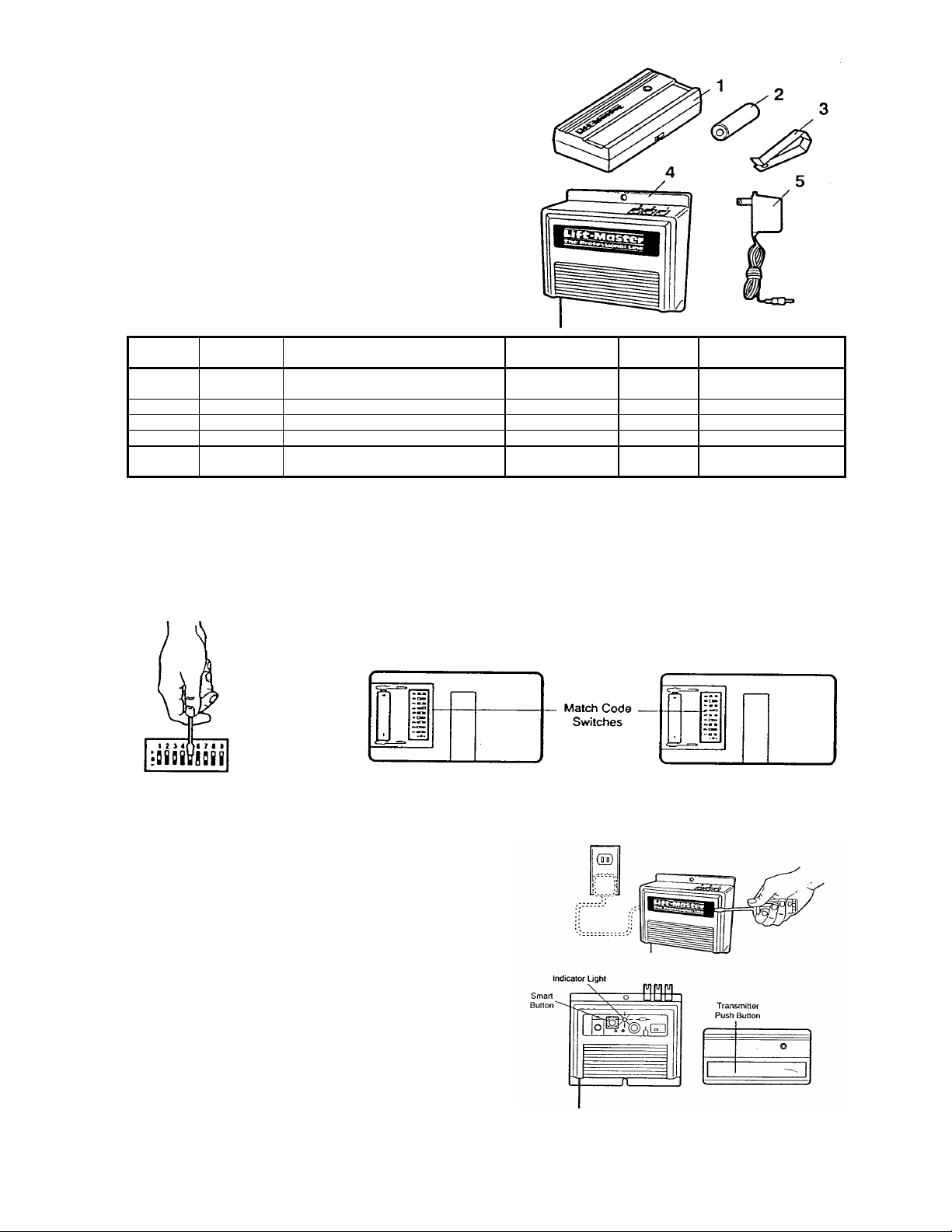
KEY
NO.
1 41A3593 Transmitter case (housing only)
2 10A14 12V Battery 5 85 Transformer Accesory
3 329C128 Visor Clip
NOT
SHOWN Model
PART
NO. DESCRIPTION
(Circuit board NOT INCLUDED)
Extra Transmitter (Complete)
61LM
KEY
NO.
4 500LM Universal Receiver
PART
NO. DESCRIPTION
MATCHING/CHANGING THE CODE
SET CODE SWITCHES IN ALL TRANSMITTERS TO MATCHING POSITIONS
1. Of the back of the transmitter(s) slide the battery compartment cover down to access the code switches.
2. With a pen or screwdriver, change the setting of one or more switch to a (+), (-) or (0) position.
3. NOTE: Code switches 2 through 9 in ALL transmitters used to operate a receiver must be set to
match. (Code switch 1 is neutral. Set it to ANY position. It will not affect the code selected).
SET RECEIVER TO MATCH TRANSMITTER CODE
1. Pry open the front panel of receiver case with a coin
screwdriver.
2. Press the “Smart” actuator on the receiver as shown. The
indicator light alongside will turn ON.
CAUTION: The door will move immediately if a neighbor or
family member is operating a remote control transmitter.
3. STAND AWAY FROM DOOR and press the transmitter
push button. The actuator indicator light will turn OFF
and the door will move. Code setting is now complete and
the opener will operate when either the wall push button or
the transmitter push is pressed. Return cover to receiver.
NOTE: If the transmitter push button is not pressed within 30
seconds, the receiver indicator light will turn OFF. Repeat
steps 1 and 2.
114A1209B
Printed in Mexico
 Loading...