

Page 1
Lift-Master
The Professional Line
Universal Receiver
Model 420LM
OWNERS MANUAL
SPECIFICATIONS
Output Rating........3 Amps 120VAC or DC Max.
Power..................................18V to 35V, @ 30ma
RF Frequency.........................................390MHz
If the power is other than shown in specifications,
Accessory Transformer Model 85 is required.
Model 86 Coaxial Cable Kit is also available.
Accessory Transmitters -- Series 50, 60, 70 and 80.
WARNING
Disconnect power to opener before installing
receiver or removing/replacing receiver cover.
The receiver and antenna use TV Type F coaxial connectors. The antenna can be plugged onto the receiver or
mounted to a bracket and connected to the receiver with Model 88 Coaxial Cable Kit, depending on your requirements.
Select a location for the receiver which allows access to the terminals and space for the antenna (as far from metal
structures as possible and preferably with the antenna in an upright position). Fasten the receiver securely with screws
through tow holes provided in the cover flanges.
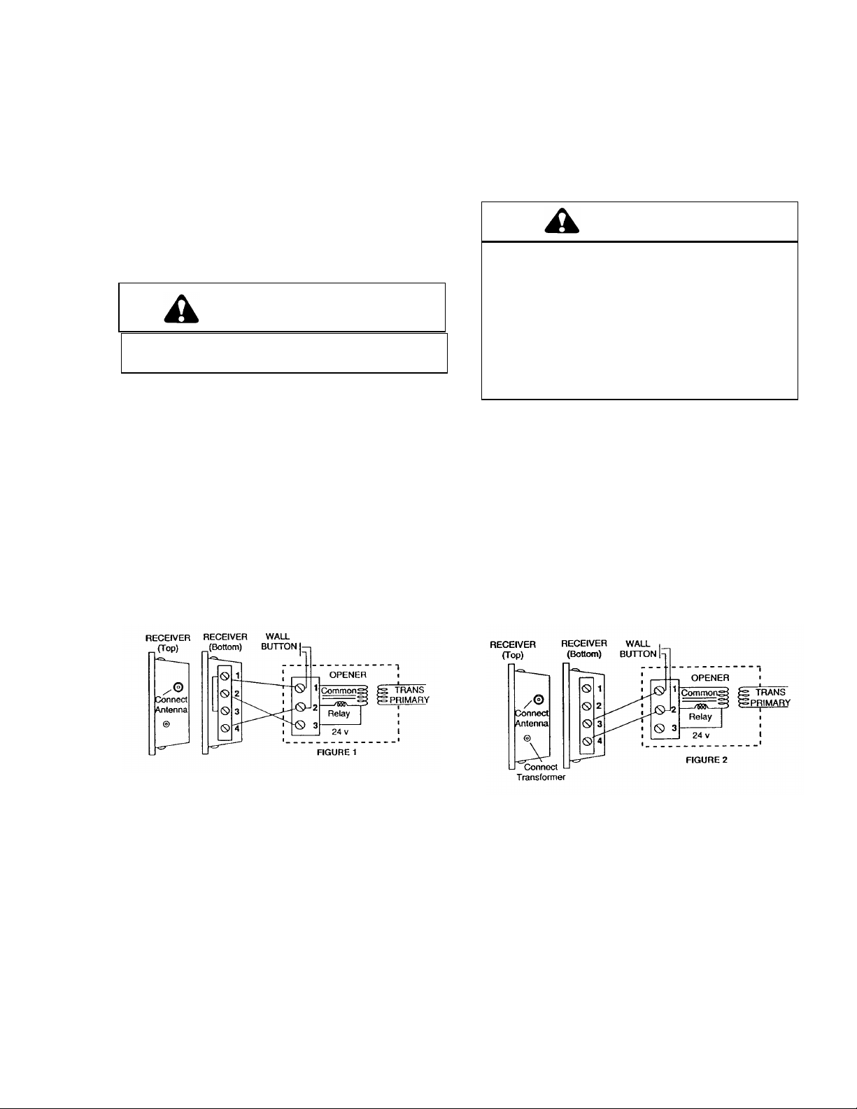
FIGURE 1 -- WITHOUT TRANSFORMER: Connect
bell wire (not supplied) to receiver terminals 1 and 2, and
to opener radio power terminals. All receiver terminals
are unpolarized.
Also connect bell wire to receiver terminal 4 and opener
terminal 2. Make a jumper wire connection to receiver
terminals 1 and 3 as shown.
To comply with FCC/IC rules, adjustment or modification of receiver
and/or transmitter is prohibited, except for changing the code setting
and replacing the transmitter battery. THERE ARE NO USER
SERVICEABLE PARTS.
WARNING
Children operating or playing with a garage
door opener can injure themselves and others.
The garage door could close and cause serious
injury or death. Do not allow children to
operate the door control push button or the
remote control transmitters.
Install the receiver (and all door control push
buttons) out of the reach of children and away
from all moving parts of the door and door
hardware but where the garage door is visible.
FIGURE -- WITH TRANSFORMER MODEL 85:
Receiver terminals 1 and 2 are not used. Connect bell
wire to receiver terminals 3 and 4 and to opener
terminals used for push button controls. The
transformer plugs into 120V outlet.
Side 2 contains code setting instructions, as well as instructions for changing output duration and voltage setting.
Page 2
SET RECEIVER TO MATCH REMOTE CONTROL(S) CODE
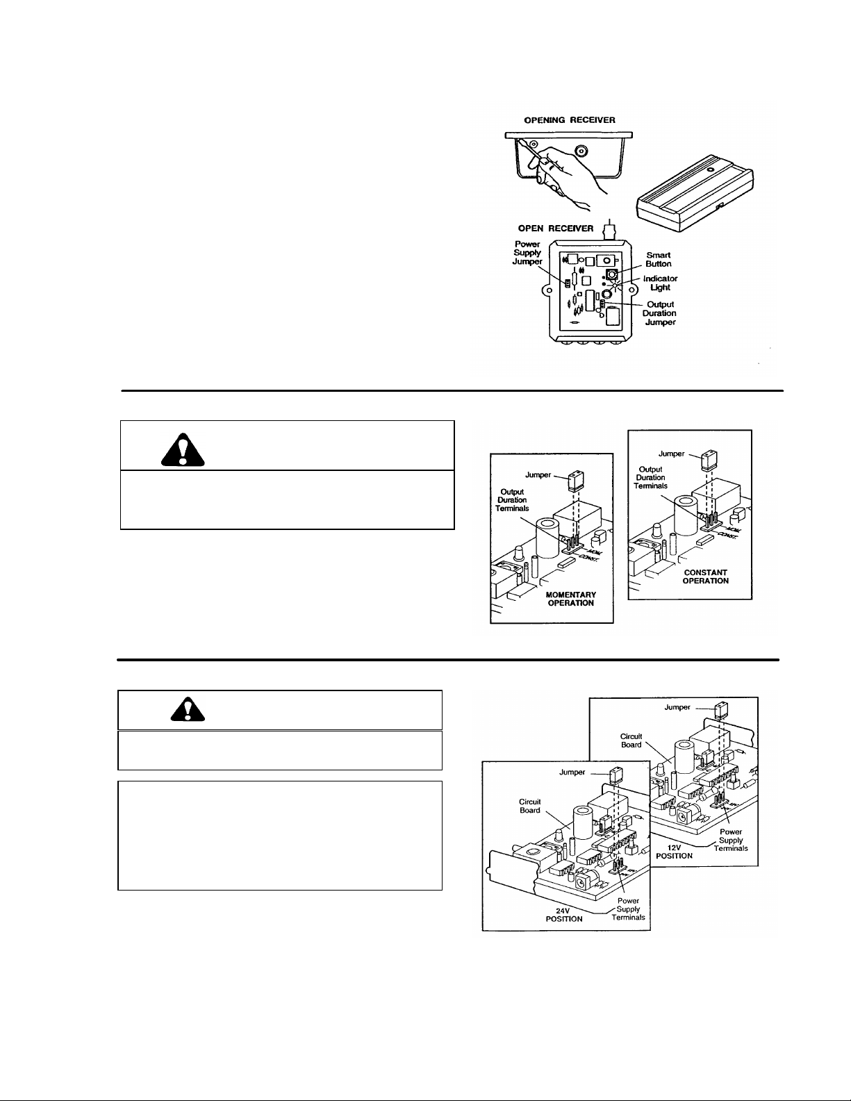
Use a screwdriver to pry open the receiver cover as
shown. Re-connect power to opener.
1. Press and HOLD the new remote control push
button.
2. Thenpress the “Smart” button on the receiver. The
adjacent indicator light will flash. Release the
remote push buitton. The opener will now operate
when the remote control push button is pressed.
Return front panel to receiver.
NOTE: If the remote control push button is not
held down until the receiver indicator light
flashes, the receiver will not learn the code.
To Erase all Remtote Control Codes
• Press and hold the “Smart” button on the receiver
panel until the indicator light turns off (about 6
seconds). All the codes the receiver has
learned will be erased.
• Repeat Steps 1 and 2 to reprogram the receiver for
each remote control transmitter in use.
TO SET OUTPUT DURATION
WARNING
The use of radios incorporating constant closure
contacts on residential operators with fail-safe
infra-red protectors is prohibited.
The receiver can be set for either constant or momentary
closure on the output contacts. With the jumper in the
“MOM” (Momentary) position, the contacts will close for
1/4 second regardless of the length of radio transmission.
With the jumper in “CONST” (Constant) position, the
contacts will stay closed as long as the radio continues
transmitting.
The receiver is factory set at M.
TO SET POWER SUPPLY VOLTAGE
CAUTION
The use 24V with the jumper in 12V postition will
cause permanent damage to the receiver.
The receiver can be powered with either 24V AC/DC or
with 12V DC. The jumper must be in the 24V position
for use with 24V, and in 12V position for use with
12VDC. The jumper must be set to the proper
voltage to avoid damage to the receiver.
The receiver is factory set at 24V.
114a1526G
© 1994, Chamberlain Group, Inc.
All Right Reserved
Printed in Mexico
Page 3

 Loading...