

Page 1
THE PROTECTOR SYSTEM
®\
The safety reversing sensor must be connected and aligned
correctly before the garage door opener will move in the
down direction. This is a required safety device and cannot
be disabled.
When properly connected and aligned, the safety reversing
sensor will detect an obstacle in the path of its electronic beam.
The sending eye (with a amber indicator light) transmits an
invisible light beam to the receiving eye (with a green indicator
light). If an obstruction breaks the light beam while the door is
closing, the door will stop and reverse to full open position, and
the opener light will flash 10 times.
The units must be installed inside the garage so that the sending
and receiving eyes face each other across the bottom of the
garage door, between 4 – 6" above the floor. Either can be
installed on the left or right of the door as long as the sun never
shines directly into the receiving eye lens. The invisible light beam
path must be unobstructed. No part of the garage door (or door
tracks, springs, hinges, rollers or other hardware) may interrupt
the beam while the door is closing.
The mounting brackets are designed to clip onto the track of
sectional garage doors without additional hardware. When
mounting the units on the wall, the brackets must be securely
fastened to a solid surface such as the wall framing.
Extension brackets provide additional clearance for wall mounting
or additional height needed for floor mounting. If installing in
masonry construction, add a piece of wood at each location to
avoid drilling extra holes in masonry if repositioning is necessary.
Facing the door from inside the garage
1
Safety Reversing Sensor Extension Bracket Kit
INSTALLING THE BRACKETS
Be sure power to the opener is disconnected.
Install and align the brackets so the sensors will face each other
across the garage door, with the beam from 4 – 6" above the floor.
They may be installed in one of three ways, depending on your
requirements, as follows.
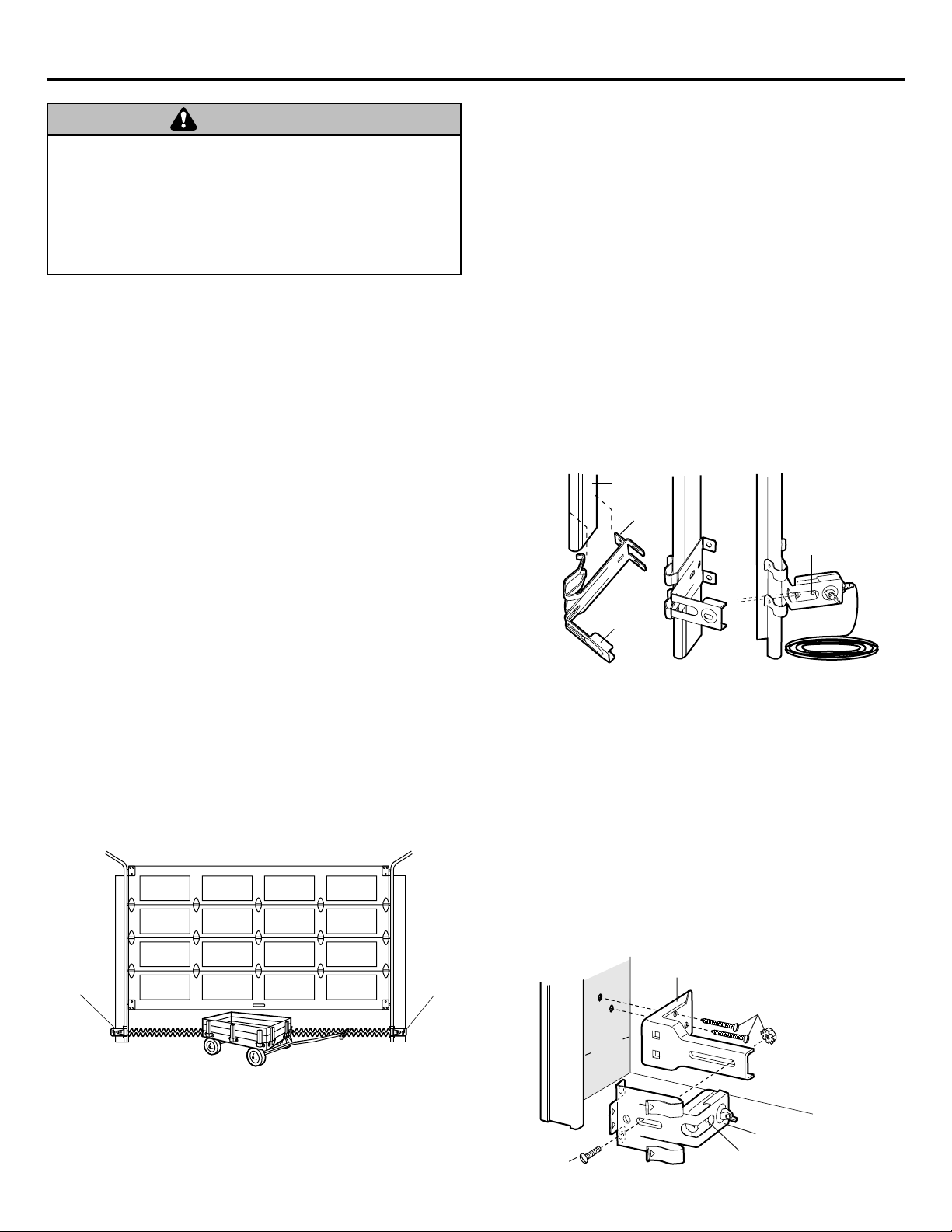
1. (Preferred) Clipped onto the left and right garage door tracks.
See Figure 2.
2. Fastened to the wall on each side of the garage. See Figure 3.
3. Fastened to the floor (see Figure 4). Concrete anchors and
wood blocks or extension brackets will be needed.
Garage Door Track Installation:
• Slip the curved arms over the rounded edge of the door track.
Snap into place against the side of the track. It should lie flush,
with the lip hugging the back edge of the track, as shown.
If your door track will not support the bracket securely, wall
installation is recommended.
Wall Installation With Extension Bracket:
• Place the bracket against the wall and make sure there is
enough clearance for the sensor beam to be unobstructed.
• If additional depth is needed, an extension bracket or wood
blocks can be used.
• Use bracket mounting holes as a template to locate and drill (2)
3/16" diameter pilot holes on the wall at each side of the door,
from 4–6" above the floor.
• Attach brackets to wall with lag screws (provided with extension
brackets).
• If using extension brackets or wood blocks, adjust right and left
assemblies to the same distance out from the mounting surface.
Make sure all door hardware obstructions are cleared.
Figure 3
Figure 2
Figure 1
Be sure power is not connected to the garage door opener BEFORE
installing the safety reversing sensor.
To prevent SERIOUS INJURY or DEATH from a closing garage door:
• Correctly connect and align the safety reversing sensor. This required
safety device MUST NOT be disabled.
• Install the safety reversing sensor so beam is NO HIGHER than 6"
(15 cm) above garage floor.
WARNING
WARNING
Sensor Beam
4-6" max.
above floor
Sensor Beam
4-6" max.
above floor
DOOR TRACK MOUNT (Right Side)
Door
Track
Lip
Indicator
light
Sensor
Bracket
Lens
WALL MOUNT (Right Side)
Extension
Bracket
(Provided with
Extension
Bracket)
Invisible Light Beam
Protection Area
Inside
arage
G
all
W
Sensor
Bracket
(Provided with
Extension Bracket)
Lens
Indicator
light
Page 2
Hardware Shown Actual Size
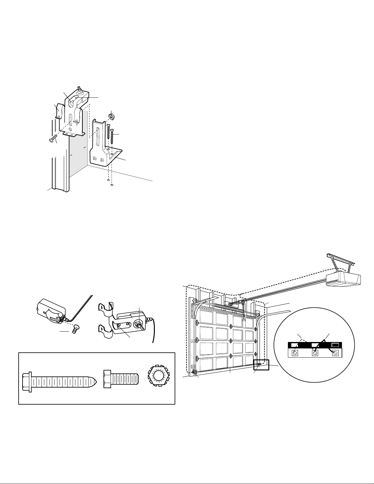
Floor installation with Extension Bracket:
• Use wood blocks or extension brackets to elevate sensor
brackets so the lenses will be 4-6" above the floor.
• Carefully measure and place right and left assemblies at the
same distance out from the wall. Be sure all door hardware
obstructions are cleared.
• Fasten to the floor with concrete anchors as shown.
Figure 4
MOUNTING AND WIRING THE SAFETY SENSORS
• Slide a 1/4"-20x1/2" carriage bolt head into the slot on both
sensors. Use wing nuts to fasten sensors to brackets, with
lenses pointing toward each other across the door. Be sure the
lens is not obstructed by a bracket extension. See Figure 5.
• Finger tighten the sensor wing nuts.
• Run the wires from both sensors to the opener. Use insulated
staples to secure wire to wall and ceiling.
• Strip 1/4" of insulation from each set of wires. Separate white
and white/black wires sufficiently to connect to the opener
terminal screws: white to 2 and white/black to 3.
ALIGNING THE SAFETY SENSORS
• Plug in the opener. The indicator lights in both the sending and
receiving eyes will glow steadily if wiring connections and
alignment are correct.
The sending eye amber indicator light will glow regardless of
alignment or obstruction. If the green indicator light in the
receiving eye is off, dim, or flickering (and the invisible light beam
path is not obstructed), alignment is required.
• Loosen the sending eye wing nut and readjust, aiming directly at
the receiving eye. Lock in place.
• Loosen the receiving eye wing nut and adjust sensor vertically
and/or horizontally until it receives the sender’s beam. When the
green indicator light glows steadily, tighten the wing nut.
TROUBLESHOOTING THE SAFETY SENSORS
1. If the sending eye indicator light does not glow steadily after
installation, check for:
• Electric power to the opener.
• A short in the white or white/black wires. These can occur at
staples, or at screw terminal connections.
• Incorrect wiring between sensors and opener.
• A broken wire.
2. If the sending eye indicator light glows steadily but the receiving
eye indicator light doesn't:
• Check alignment.
• Check for an open wire to the receiving eye.
3. If the receiving eye indicator light is dim, realign either sensor.
NOTE: When the invisible beam path is obstructed or misaligned
while the door is closing, the door will reverse. If the door is
already open, it will not close. The opener lights will flash 10
times. (If bulbs are not installed, 10 clicks can be heard.)
See page 1.
Figure 5
Figure 6
© 2006, The Chamberlain Group
114A2401B All Rights Reserved
FLOOR MOUNT (Right Side)
Sensor
Bracket
Extension
Bracket
Lens
Indicator
light
Attach with
concrete anchors
(not provided)
Inside
G
arage
W
all
(Provided with
Extension Bracket)
(Provided with
Extension
Bracket)
Wing nut
1/4"-20x1/2"
Carriage bolt
Lens
1/4x1-1/2"
Lag Screw (4)
1/4-20x5/8 Hex Bolt (2)
Sensor
1/4" - 20
Lock Nut ª2)
Bell Wire
Invisible Light Beam
Protection Area
Sensor
Connect Wire to
Opener Terminal Screws
Door Control
Connections
(dotted line)
1
OPENER TERMINAL SCREWS
Sensor
Connections
2 3
 Loading...