

Page 1
All Rights Reserved
OWNERS MANUAL Model 400 Lift-Master Universal Receiver
F.C.C. rules prohibit adjustments to or modification of receiver and/or transmitter circuitry except for changing the code setting and replacing the transmitter
Accessory Transmitters - Series 50 and 60
battery. THERE ARE NO USER SERVICEABLE PARTS.
Manufactured under 1 or more of the following U.S. patents: RE29,525; 4,037,201; 4,750,118; 4,&0ff,93Ct—Other Patents Pending
Output Rating.......................................... 3 Amps 120VAC or DC Max.
SPECIFICATIONS
Power........................................................................ 18V to 35V, @ 30ma
RF Frequency................................ ................................ .............. 390MHz
DISCONNECT POWER TO OPENER BEFORE INSTALLING RECEIVER OR REMOVING/REPLACING RECEIVER COVER .
The receiver and antenna use TV Type F coaxial connectors. The antenna can be plugged directly onto the receiver or mounted to a bracket and connected to the
receiver with Model 86 Coaxial Cable Kit, depending on your requirements.
Select a location for the receiver which allows access to the terminals and space for the antenna (as far from metal structures as possible and preferably with the
antenna in an upright position). Fasten the receiver securely with screws through the two holes provided in the cover flanges.
If the power is other than shown in specifications, Accessory
Transformer Model 85 is required. Model 86 Coaxial Cable Kit is also
available.
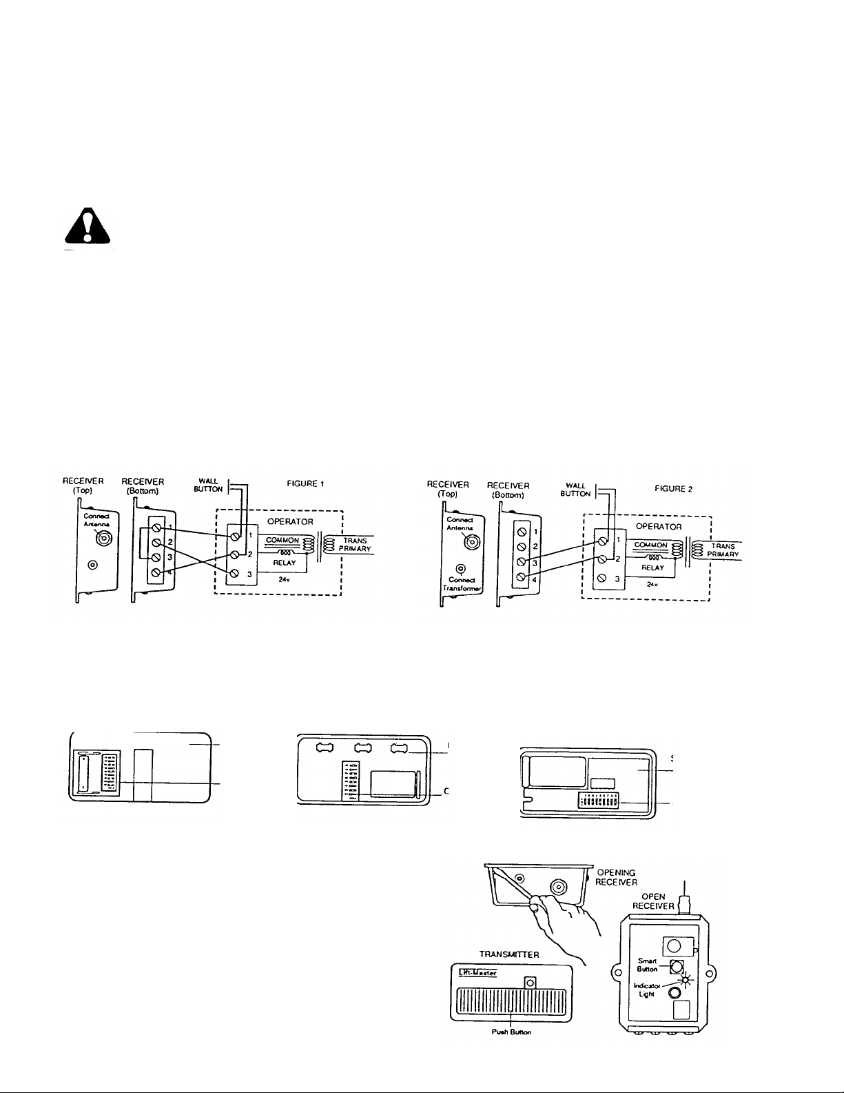
FIGURE 1—WITHOUT TRANSFORMER: Connect bell wire (not
supplied) to receiver terminals 1 and 2, and to opener radio power
terminals. (On openers with terminals labeled 1, 2 and 3, radio power
terminals will usually be 1 and 3). All terminals are unpolarized.
Also connect bell wire to receiver terminal 4 and operator terminal 2.
Make a jumper wire connection to receiver terminal 1 and 3.
FIGURE 2—WITH TRANSFORMER MODEL 85: Receiver terminals 1 and 2
are not used. Connect bell wire to receiver terminals 3 and 4 and to opener
relay control terminals 1 and 2. The transformer plugs into a 120V outlet.
MATCHING/CHANGING THE CODE
SET CODE SWITCHES IN ALL TRANSMITTERS TO MATCHING POSITIONS
Code switch locations in three of the available accessory transmitters are shown below. If more than one transmitter will be used to operate your garage door opener,
the code switches in ALL transmitters must be set to the same positions. Please refer to the instruction sheet packed with your transmitter for code setting
procedures.
Multi-Function
Transmitter
63LM
Code Switches
(1-9)
Multi-Function
Transmitter
53LM
Code Switches
(2-9)
Single Function
Transmitter
51LM
Code Switches
(1-9)
SET RECEIVER TO MATCH TRANSMITTER(S) CODE
3. Disconnect power to opener. Use a screwdriver to pry open the
receiver cover as shown. Re-connect power to opener.
4. Press the "Smart button on the receiver. The indicator light alongside
will turn ON.
5. STAND AWAY FROM DOOR and press the transmitter push
button. The indicator light will turn OFF and the door will move. Code
setting is now complete. Snap cover back on receiver.
NOTE: If the transmitter push button is not pressed within 30
seconds, receiver indicator light will turn OFF Repeat Steps 4
and 5.
114A1266B Printed in Mexico
1990 The Chamberlain Group,Inc
 Loading...