

Page 1
®
C
o
m
p
a
t
i
b
l
e
w
i
t
h
S
e
e
P
a
g
e
1
4
f
o
r
D
e
t
a
i
l
s
Model 3800PC
GARAGE DOOR OPENER
For Residential and Light Duty Commercial Use
Install On Sectional Doors With Torsion
Assemblies Only
The Chamberlain Group, Inc.
845 Larch Avenue
Elmhurst, Illinois 60126-1196
www.liftmaster.com
■ Please read this manual and the enclosed safety materials carefully!
■ Fasten the manual near the garage door after installation.
■ The door WILL NOT CLOSE unless the Protector System® and cable tension monitor are
connected and properly aligned.
■ Periodic checks of the garage door opener are required to ensure safe operation.
■ The model number label is located behind the hinged door of your opener.
■ DO NOT exceed 10 complete cycles of door operation per hour.
Page 2

Table of Contents
INTRODUCTION 2-5
Safety Symbol and Signal Word Review .. 2
Planning ................................................... 3
Preparing Your Garage Door .................... 4
Tools N eeded ........................................... 4
Specifications ........................................... 4
Carton Inventory ...................................... 5
Hardware Inv entory .................................. 5
ASSEMBLY 6-7
Attach the Collar to the
Garage Door Opener ................................6
Attach Mounting Bracket to the
Garage Door Opener ................................7
INSTALLATION 7-18
Installation Safety Instructions .................7
Position and Mount the Garage Door
Opener ..................................................... 8
Attach the Emergency Release Rope
and Ha ndle ............................................... 9
Install Power Door Lock ...........................9
Attach the Cable Tension Monitor
(Required) .............................................. 10
Install the Smart Control Panel
Install Remote Light ............................... 12
Electrical Requirements ......................... 13
Install the EverCharge®
Standby Power System (optional) ..........14
Install The Protector System® ........... 15-18
®
............ 11
ADJUSTMENT 19-22
Program the Travel Limits ......................19
Set the Force .......................................... 20
Test the Safety Reversal System ............ 21
Test The Protector System® ................... 21
Test Cable Tension Monitor ...................22
Test Power Door Lock ............................22
To Open Door Manually .........................22
OPERATION 23-29
Operation Safety Instructions .................23
Using Your Garage Door Opener ............23
®
Using the Smart Control Panel
............. 24
Using the Remote Control ...................... 25
Care of Your Garage Door Opener ..........26
Troubleshooting ................................ 26-27
Smart Control Panel® Me ssages ............ 28
Diagnostic Chart .................................... 29
PROGRAMMING 30-32
To Add or Reprogram a Hand-Held
Remote Control (Model 895MAX) .......... 30
To Erase All Codes From Garage Door
Opener Me mory ..................................... 30
To Add, Reprogram or Change a
Keyless Entry PIN ...................................31
Programming Light or Additional Light ..32
REPAIR PARTS 33-34
Installation Pa rts .................................... 33
Garage Door Opener Assembly Parts ..... 34
ACCESSORIES 35
REPAIR PARTS AND SERVICE 36
WARRANTY 36
Introduction
Safety Symbol and Signal Word Review
This garage door opener has been designed and tested to offer safe service provided it is installed, operated, maintained and tested in
strict accordance with the instructions and warnings contained in this manual.
When you see these Safety Symbols and Signal Words on the following pages, they
will alert you to the possibility of serious injury or death if you do not comply with the
warnings that accompany them. The hazard may come from something mechanical or
from electric shock. Read the warnings carefully.
When you see this Signal Word on the following pages, it will alert you to the possibility
of damage to your garage door and/or the garage door opener if you do not comply with
the cautionary statements that accompany it. Read them carefully.
2
Mechanical
Electrical
Page 3
Introduction
Planning
Survey your garage area to see if any of the conditions below apply to your installation.
Depending on your requirements, additional materials may be required.
THIS GARAGE DOOR OPENER IS COMPATIBLE WITH:
• Doors that use a torsion bar and springs. The torsion bar must be 1 inch (2.5 cm)
diameter.
• 4-6 inch (10-15 cm) drums, not to be used on tapered drums over 6 inches (15 cm).
• High lift and standard lift sectional doors up to 14 feet (4.2 m) high.
• Doors up to 18 feet (5.4 m) wide.
• Doors up to 180 sq. ft. (16.7 sq. m).
Review or inspect proposed installation area. The garage door opener can be installed on
the left or right side of door. Select the side that meets the requirements listed below.
Must have minimum of 2-1/2 inches
a
(6.4 cm) between the garage wall and
the center of the torsion bar.
Must have minimum of 3 inches
b
(7.6 cm) between the ceiling and the
center of torsion bar.
Must have minimum of 8 inches
c
(20.3 cm) between the side garage
wall (or obstruction) and the end of
torsion bar.
8 inches
c
(20.3 cm)
torsion bar
wall or
obstruction
d
NOTE: Inspect the torsion bar while the
door is raised and lowered. It is important
that there is no noticeable movement up
and down or left and right. If the movement
is not corrected, the life of the garage door
opener will be greatly reduced.
3 inches
b
(7.6 cm)
a
2-1/2 inches
(6.4 cm)
torsion
bar
Remote light
The torsion bar must extend at least
d
1-5 inches (2.5-12 cm) past the
bearing plate.
An electric outlet is required within
e
6 feet (1.8 m) of the installation area.
If outlet does not exist, contact a
qualifi ed electrician.
f
Depending upon garage construction,
extension brackets or wood blocks
may be needed to install safety
reversing sensors.
Alternate fl oor mounting of the
g
safety reversing sensors will require
hardware not provided.
Any gap between the fl oor and the
h
bottom of the door must not exceed
1/4 inch (6 mm), otherwise the
safety reversal system may not work
properly.
A model 475LMC EverCharge®
i
Standby Power System is strongly
recommended if there is no access
door to the garage, as this garage door
opener cannot be used in conjunction
with an external emergency release
mechanism.
e
Safety reversing
sensor
g
f
h
475LMC EverCharge® Standby
i
Power System
3
Page 4
Introduction
Preparing Your Garage Door
BEFORE YOU BEGIN:
• Disable locks.
• Remove any ropes connected to the
garage door.
Complete the following test to make sure
the garage door is balanced and is not
sticking or binding:
1. Lift the door halfway up. Release the
door. If balanced, it should stay in place,
supported entirely by its springs.
2. Raise and lower the door to check for
binding or sticking.
If your door binds, sticks, or is out of
balance, call a trained door systems
technician.
3. Verify equal cable tension on each side of
door. Cable tension should remain equal
during the entire travel of the door.
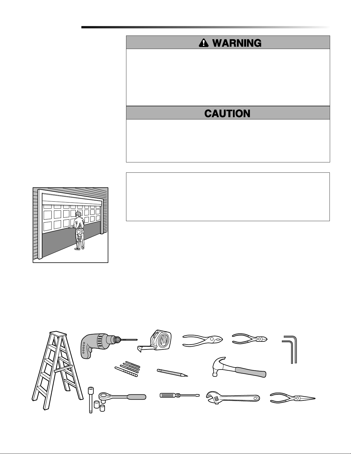
To prevent possible SERIOUS INJURY or DEATH:
• ALWAYS call a trained door systems technician if garage door binds, sticks, or is
out of balance. An unbalanced garage door may NOT reverse when required.
• NEVER try to loosen, move or adjust garage door, door springs, cables, pulleys,
brackets or their hardware, ALL of which are under EXTREME tension.
• Disable ALL locks and remove ALL ropes connected to garage door BEFORE
installing and operating garage door opener to avoid entanglement.
To prevent damage to garage door and opener:
• ALWAYS disable locks BEFORE installing and operating the opener.
• ONLY operate garage door opener at 120 V, 60 Hz to avoid malfunction and
damage.
• DO NOT exceed 10 complete cycles of door operation per hour.
Specifi cations
Volts . . . . . . . . . . . . . . . . . . . . . . . . . . . . . . . . . . . . . . . . . . . 120 Vac - 60 Hz, ONLY
Current . . . . . . . . . . . . . . . . . . . . . . . . . . . . . . . . . . . . . . . . . . . . . . . . . . . . 1.0 AMP
Rated Load . . . . . . . . . . . . . . . . . . . . . . . . . . . . . . 325 in. lb/sec 10 Cycles per Hour
Sectional Door
Tools Needed
During assembly, installation and adjustment of the garage door opener, instructions will
call for hand tools as illustrated below.
2
Stepladder
Drill
5/32", 3/16", 5/16"
and 3/4" Drill Bits
1/4", 5/16" & 3/8" Sockets
and Wrench with 6" Extension
1
Tape Measure
Pencil
Screwdriver
Torque Meter (not shown)
Pliers
Adjustable End Wrench
Wire Cutters
Claw Hammer
3/16" and 1/8"
Hex Key Wrench
Needle Nose Pliers
4
Page 5
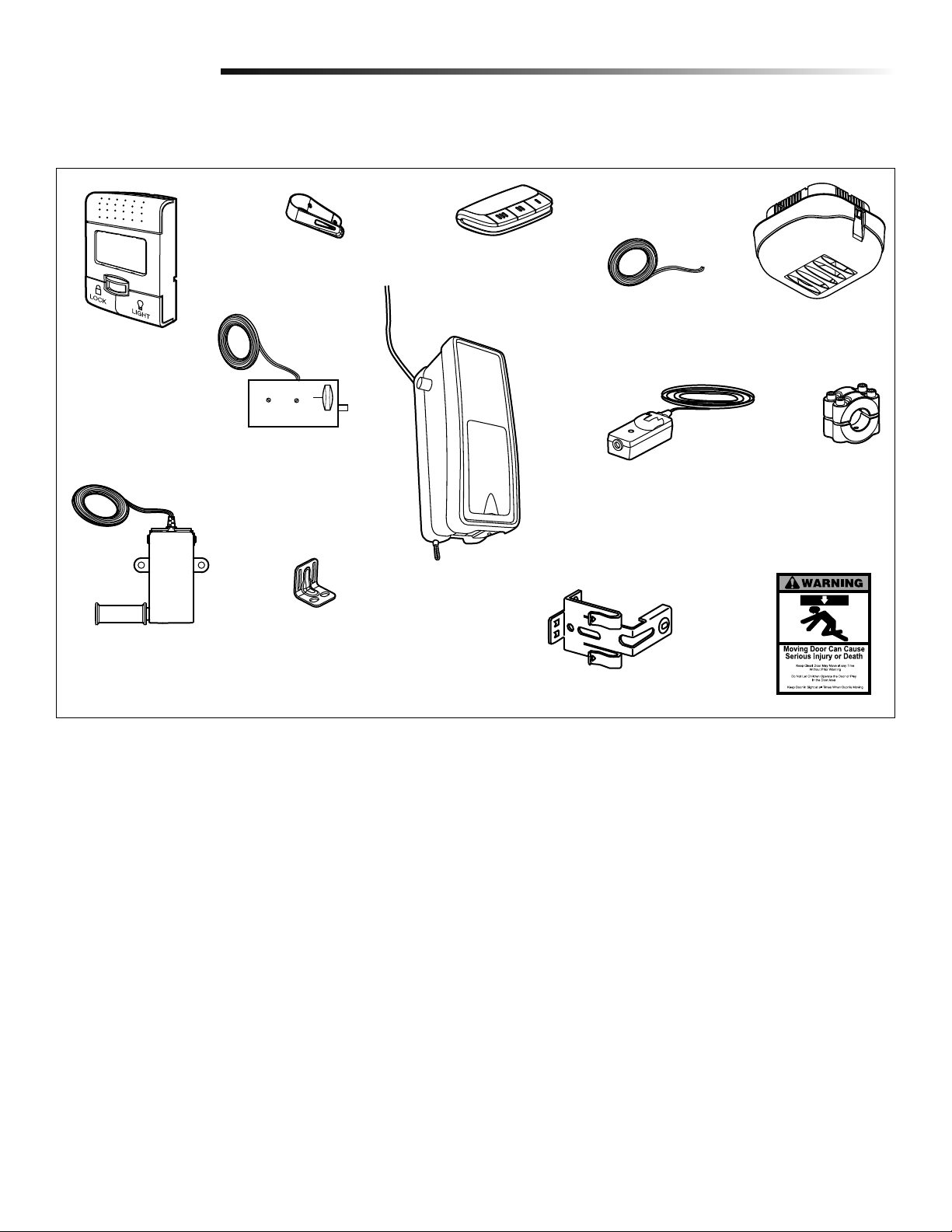
Introduction
Carton Inventory
Accessories included with the garage door opener will vary depending on the model purchased. If anything is missing, carefully check
the packing material.
Smart Control Panel
Cable Tension Monitor
with 2-Conductor
Green/White Bell Wires
Remote Control
Visor Clip
®
Power Door Lock with
2-Conductor White & White/
Black Bell Wire with Connector
Mounting Bracket
3-Button Remote Control
Model 895MAX (1)
Garage Door Opener
2 Conductor Bell Wire
White & White/Red
The Protector System
(2) Safety Reversing Sensors
(1 Sending Eye and 1 Receiving
Eye) with 2-Conductor White &
White/Black Bell Wire attached
Safety Reversing Sensor Bracket (2)
®
Remote Light
(Garage Door Opener Light)
with Hardware Bag
Collar with Screws
Safety Labels
and Literature
Hardware
Hex Screw #14-10x1-7/8" (4)
Screw #6x1-1/4" (2)
Machine Screw #6x1" (2)
Carriage Bolt 1/4"-20x1/2" (2)
Wing Nut 1/4"-20 (2)
Pan Head Screw 1/4"-20x1/2" (2)
Hex Head Screw #8x1" (2)
Self Tapping Screw #10-32 (2)
Drywall Anchor (2)
Drywall Anchor (Screw-In) (4)
Handle
Rope
Insulated Staples (10)
Lock Template
5
Page 6
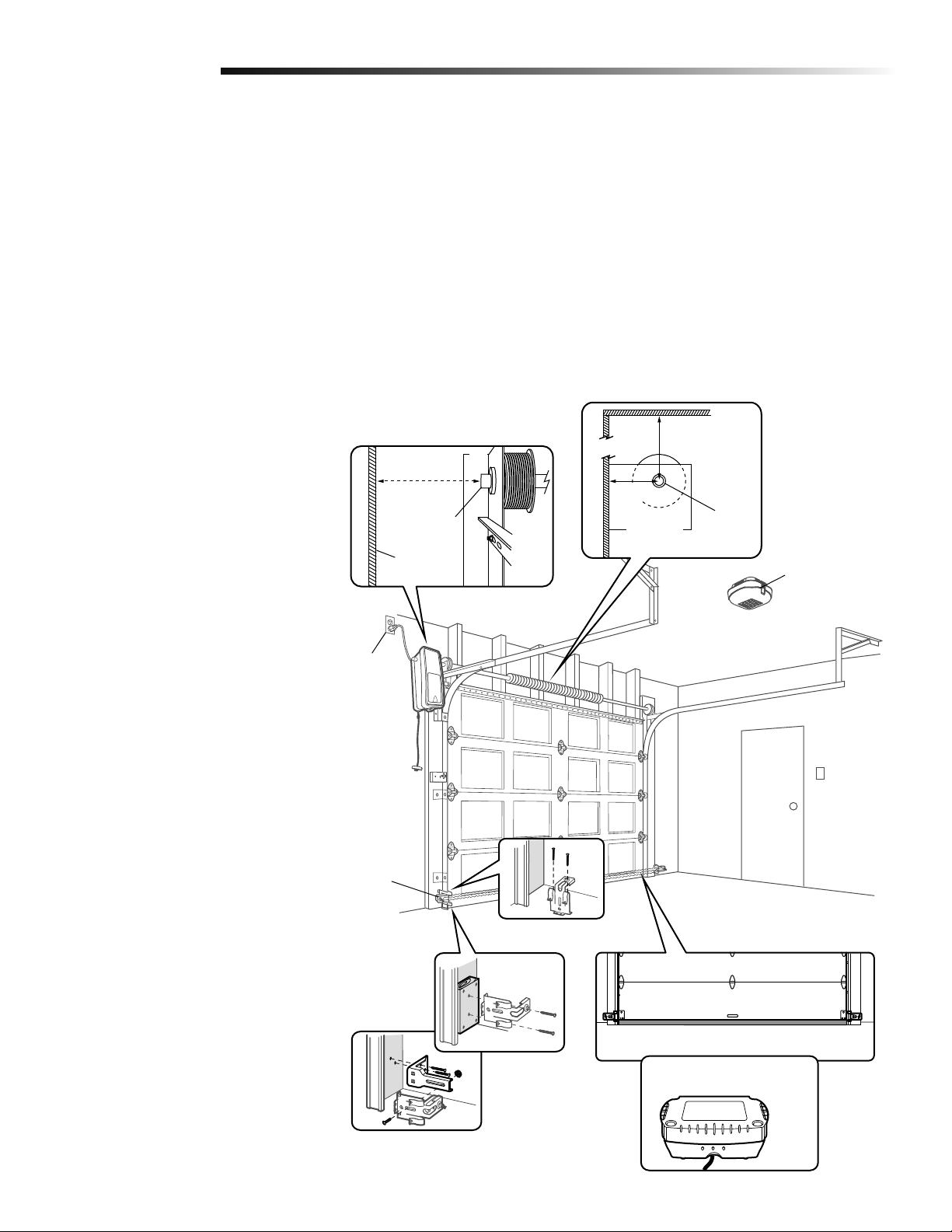
Assembly
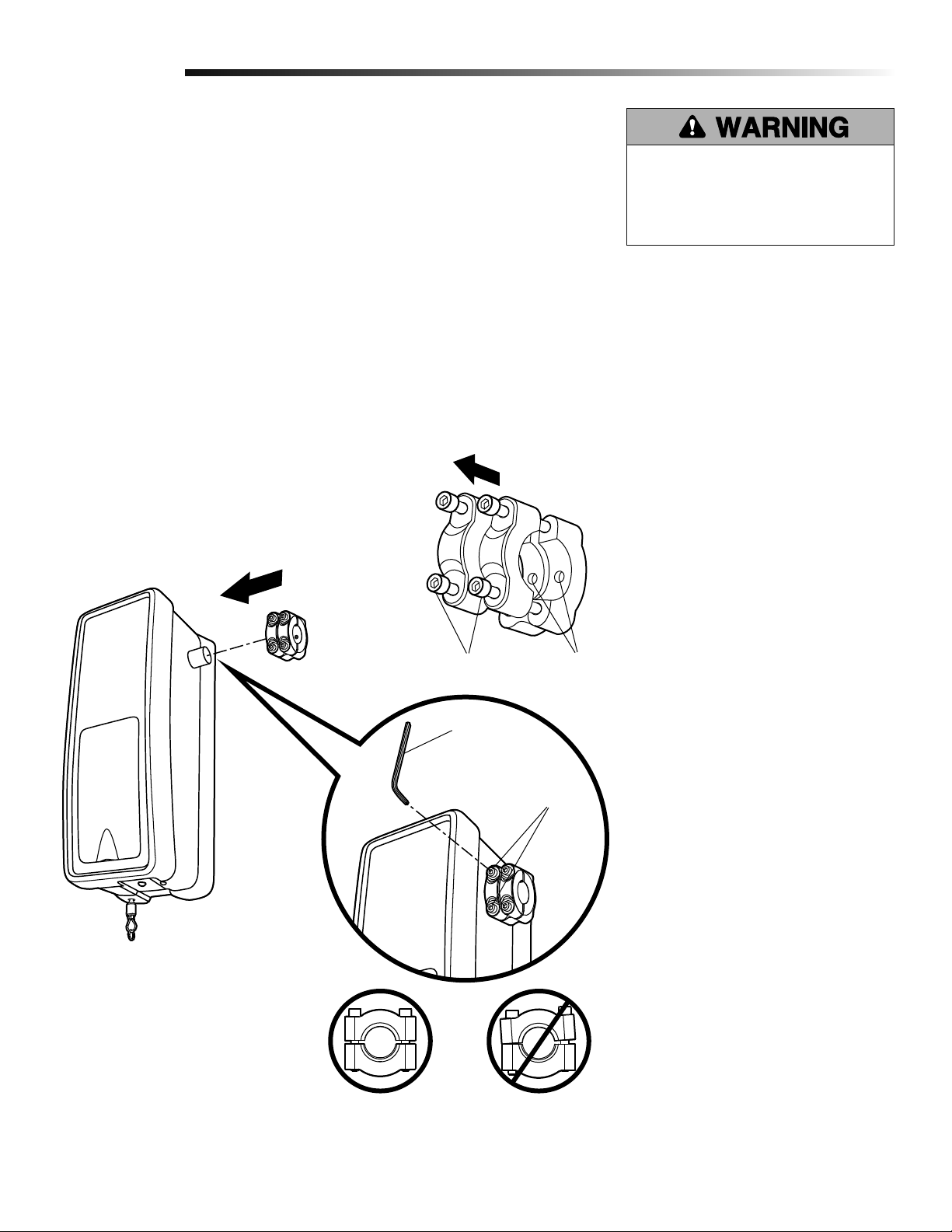
Attach the Collar to the Garage Door Opener
1
To avoid installation diffi culties, do not run the garage door garage door opener until instructed
to do so.
The garage door opener can be installed on either side of the door (see PLANNING section
page 3). The illustrations shown are for installation on the left side.
Loosen the collar screws.
1
Attach collar to the garage door opener motor shaft. The side of the collar with the
2
larger hole should be placed on the motor shaft. Ensure that the collar is seated all the
way on motor shaft until stop is reached.
Position the collar so the screws are facing out and are accessible when attached to
3
the torsion bar.
Tighten the screws on both sides of the collar equally to secure collar to the motor
4
shaft (to 12-14 ft./lbs. of torque).
NOTE: Do not tighten set screws until indicated.
1
To prevent possible SERIOUS INJURY
or DEATH, the collar MUST be properly
tightened. The door may NOT reverse
correctly or limits may be lost due to
collar slip.
2
Collar Screws Set Screws
3/16 Hex
Key Wrench
4
Collar Screws
3
RIGHT WRONG
6
Page 7
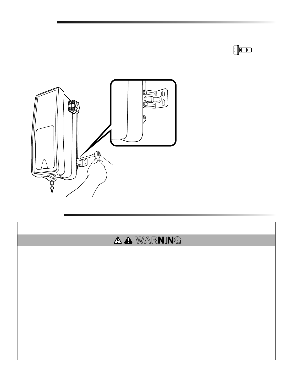
Assembly
Attach Mounting Bracket to Garage Door Opener
2
Loosely attach slotted side of mounting bracket to the same side of the garage door
1
opener as the collar, using self-threading screws provided.
NOTE: Do not tighten screws until instructed.
1
Socket Wrench
HARDWARE
Screw
#10-32
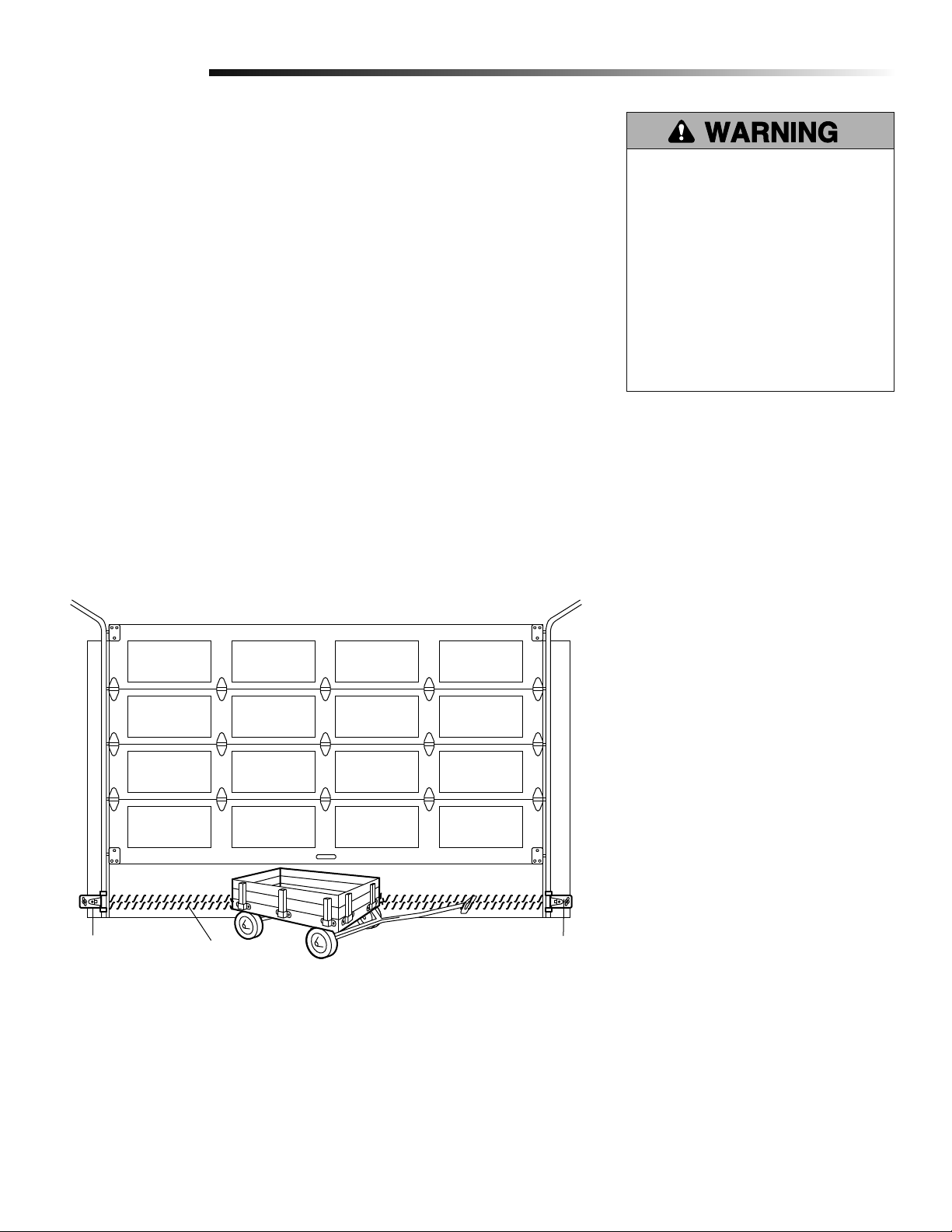
Installation
IMPORTANT INSTALLATION INSTRUCTIONS
To reduce the risk of SEVERE INJURY or DEATH:
1. READ AND FOLLOW ALL INSTALLATION WARNINGS AND
INSTRUCTIONS.
2. Install door operator ONLY on properly balanced and
lubricated door. An improperly balanced door may NOT
reverse when required and could result in SEVERE INJURY
or DEATH.
3. ALL repairs to cables, spring assemblies and other
hardware MUST be made by a trained door systems
technician BEFORE installing garage door opener.
4. Disable ALL locks and remove ALL ropes connected to
door BEFORE installing garage door opener to avoid
entanglement.
5 Mount the emergency release within reach, but at least 6
feet (1.83 m) above the fl oor and avoiding contact with
vehicles to avoid accidental release.
6. NEVER connect door operator to power source until
instructed to do so.
WARNING
7. NEVER wear watches, rings or loose clothing while
installing or servicing the garage door opener. They could
be caught in door or operator mechanisms.
8. Install wall-mounted door control:
• within sight of the door.
• out of reach of children at minimum height of 5 feet
(1.5 m).
• away from ALL moving parts of the door.
9. Install the Entrapment Warning Placard next to the door
control in a prominent location.
10. Place manual release/safety reverse test label in plain view
on inside of door.
11. Upon completion of installation, test safety reversal
system.
7
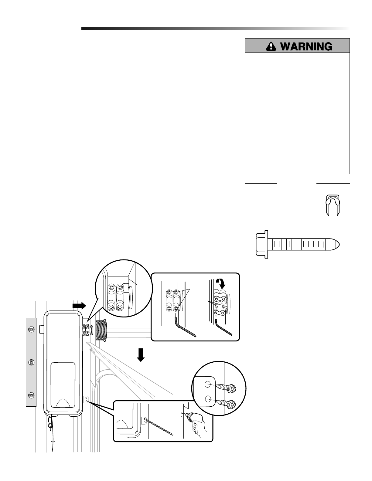
Page 8
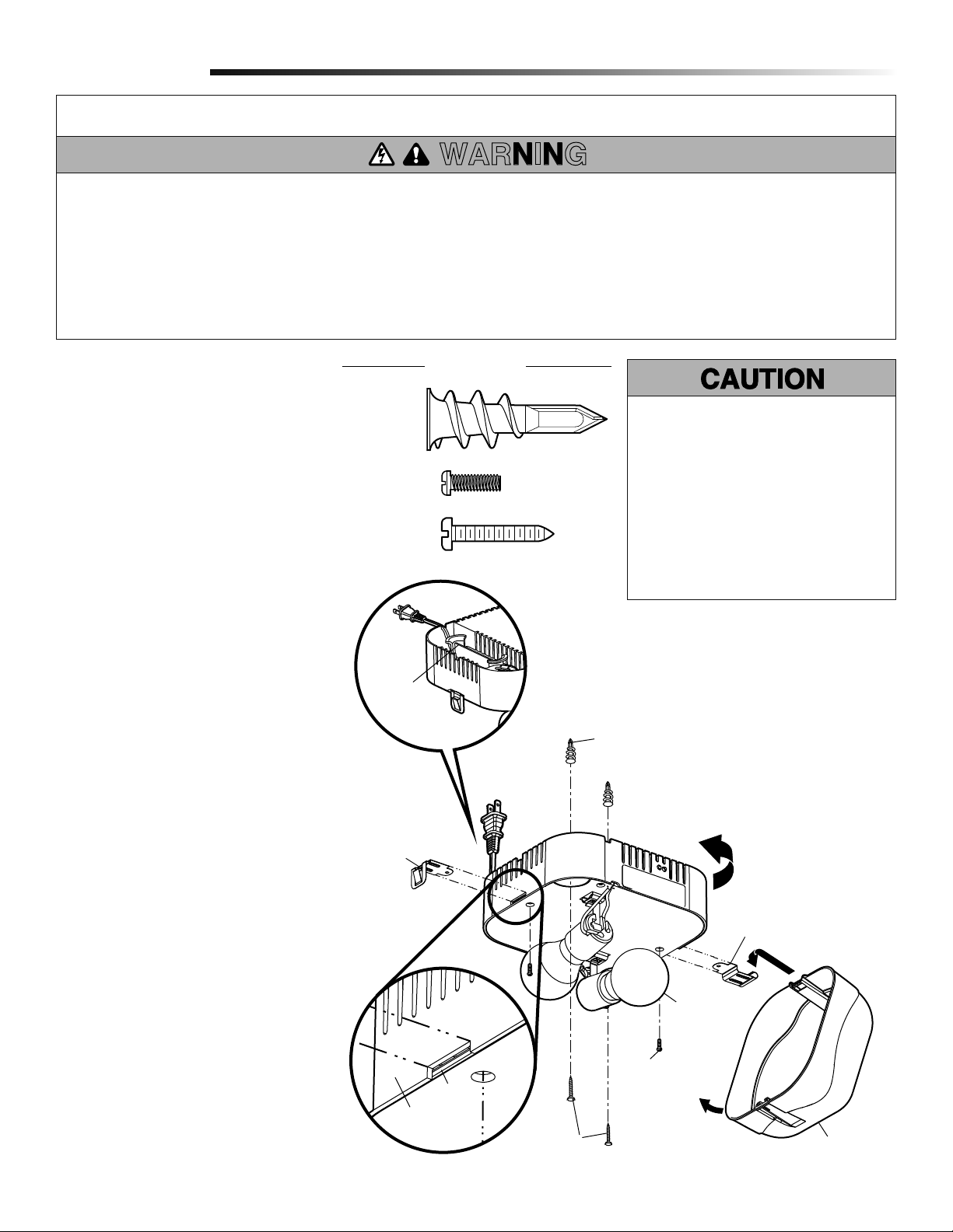
Installation
Position and Mount the Garage Door Opener
1
NOTE: For additional mounting options refer to the accessories page.
Close the garage door completely.
1
Slide the garage door opener onto the end of the torsion bar. If the torsion bar is too
2
long or damaged, you may need to cut the torsion bar. Ensure the collar does not
touch the bearing plate.
Use a level to position and vertically align the garage door opener. Verify the
3
mounting bracket is located on a solid surface such as wood, concrete or door/fl ag
bracket.
When the garage door opener is properly aligned, mark the mounting bracket holes.
4
If necessary, tighten collar screws on the torsion bar to hold garage door opener in
place while marking holes.
NOTE: The garage door opener does not have to be fl ush to wall.
Remove the garage door opener from torsion bar. Drill 3/16 inch pilot holes at the
5
marked locations. Drill through steel plate if necessary.
6
Slide the garage door opener back onto the torsion bar until pilot holes align with
bracket. Securely tighten collar screws to the torsion bar to 12-14 ft./lbs. of torque.
Securely tighten both set screws.
7
NOTE: You may need to manually raise the door slightly in order to reach the
set screws.
Secure the mounting bracket to the wall and to the garage door opener. Use the
8
14-10x1-7/8 inch screws to secure the mounting bracket to the wall.
To prevent possible SERIOUS INJURY
or DEATH:
• Concrete anchors MUST be used if
mounting bracket into masonry.
• NEVER try to loosen, move or adjust
garage door, springs, cables, pulleys,
brackets or their hardware, ALL of
which are under EXTREME tension.
• ALWAYS call a trained door systems
technician if garage door binds,
sticks or is out of balance. An
unbalanced garage door might NOT
reverse when required.
• Operator MUST be mounted at a
right angle to the torsion bar to avoid
premature wear on the collar.
HARDWARE
Staple
14-10x1-7/8" Hex Screw
Secure the antenna wire with a staple to prevent antenna from being entangled in a
9
door roller.
2
7
Bearing
Plate
6
Collar
Screws
Set
Screws
3
3/16" Hex
Key Wrench
1/8" Hex
Key Wrench
1
4
5
8
9
8
Page 9
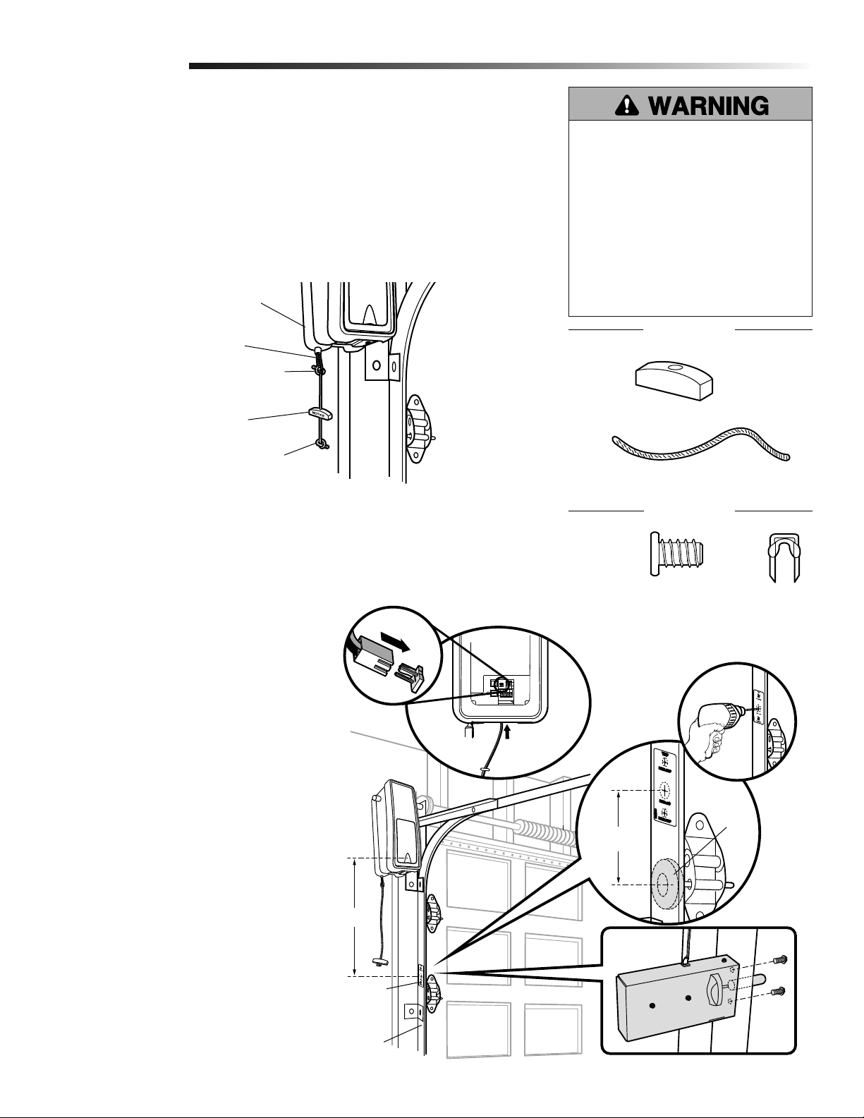
Installation
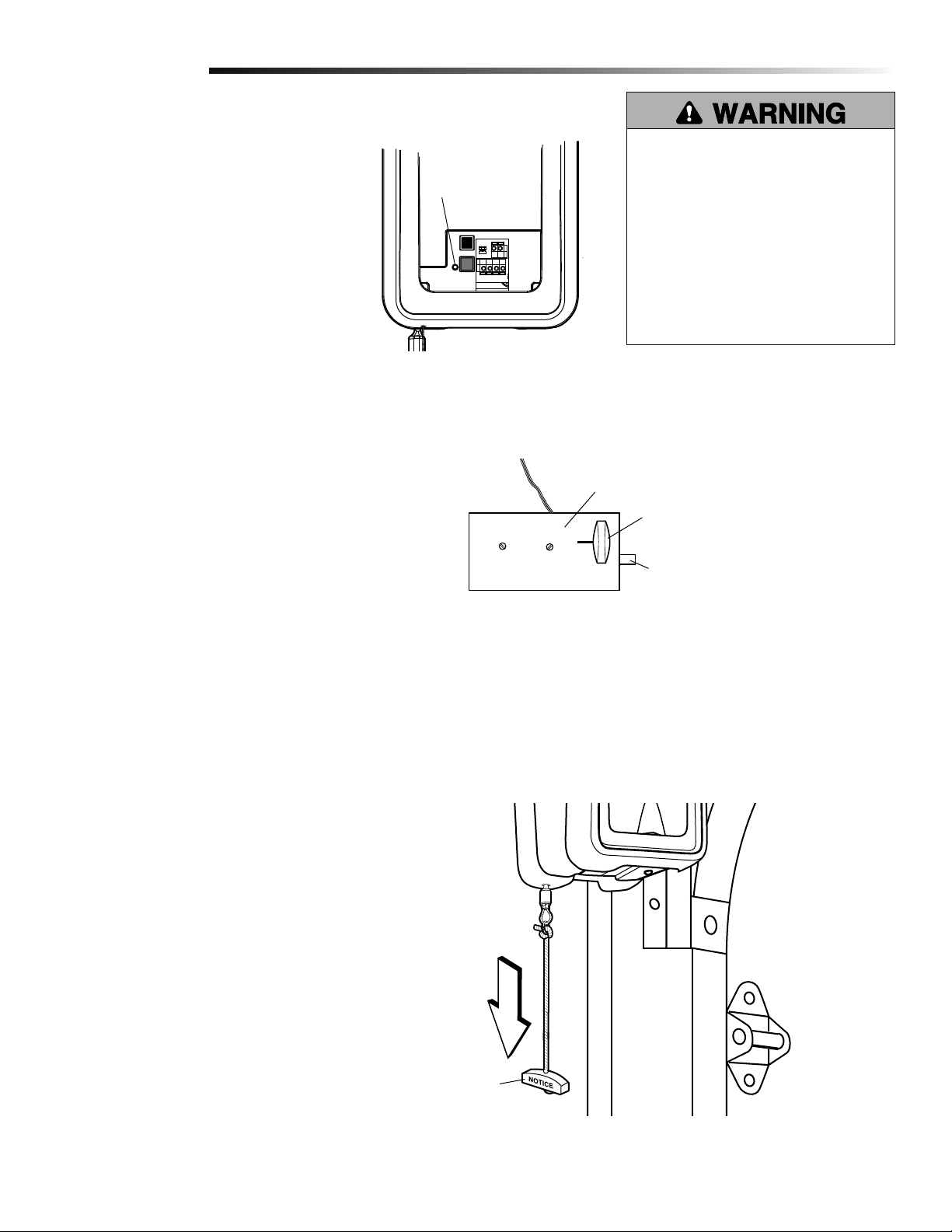
Attach the Emergency Release Rope and Handle
2
1
Thread one end of the rope through the hole in the top of the red handle so “NOTICE”
reads right side up as shown. Secure with an overhand knot at least 1 inch (2.5 cm)
from the end of the rope to prevent slipping.
2
Thread the other end of the rope through the loop in the emergency release cable.
Adjust rope length so the handle is no higher than 6 feet (1.83 m) above the fl oor.
Secure with an overhand knot.
NOTE: If it is necessary to cut the rope, heat seal the cut end with a match or lighter
to prevent unraveling.
Garage door opener
To prevent possible SERIOUS INJURY
or DEATH from a falling garage door:
• If possible, use emergency release
handle to disengage door ONLY when
garage door is CLOSED. Weak or
broken springs or unbalanced door
could result in an open door falling
rapidly and/or unexpectedly.
• NEVER use emergency release handle
unless garage doorway is clear of
persons and obstructions.
Emergency
Release Cable
Overhand
Knot
Emergency
Release Handle
Overhand
Knot
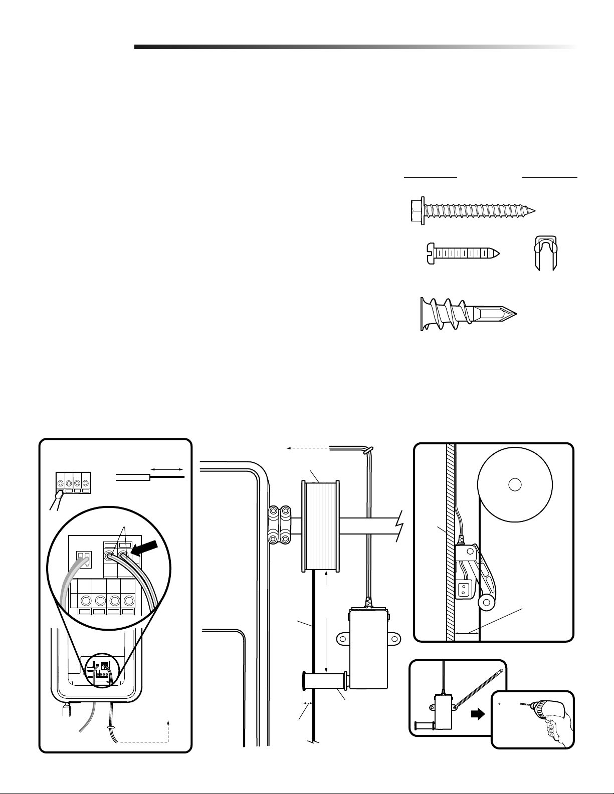
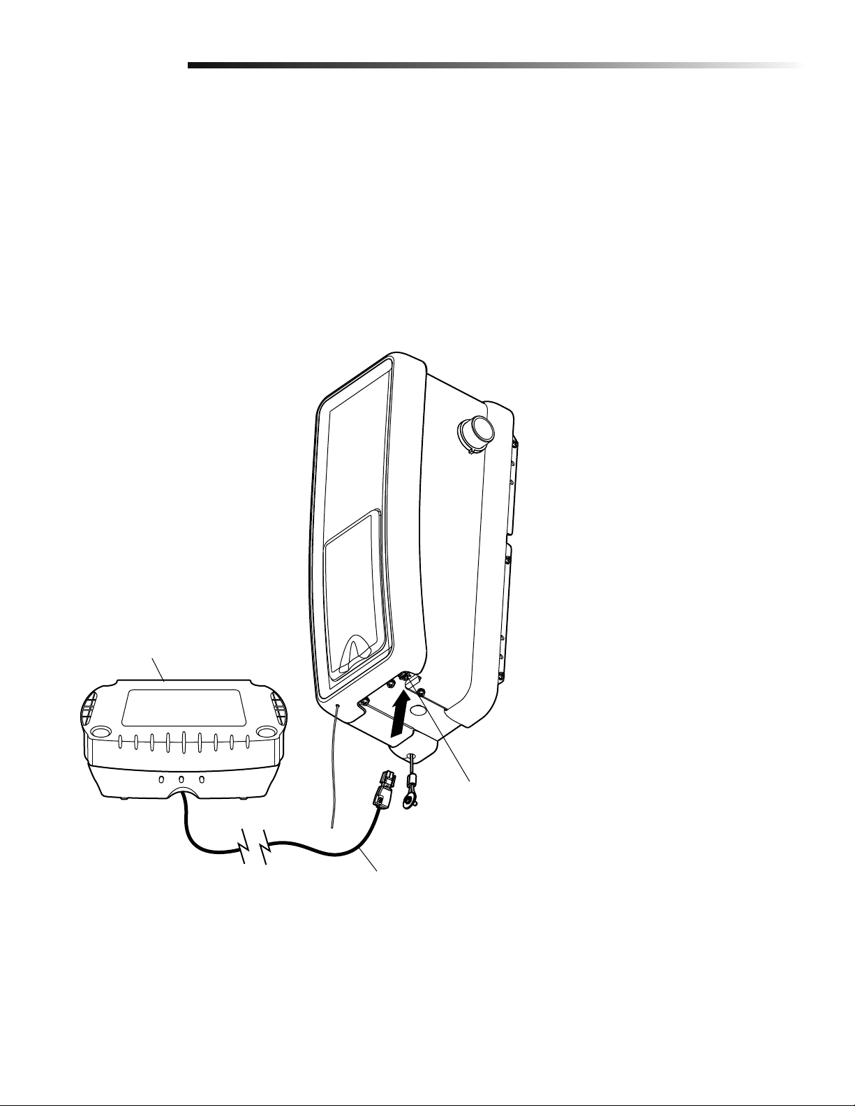
Install Power Door Lock
3
The power door lock is used to prevent the garage door from being manually opened once the
door is fully closed.
1
The power door lock must be mounted
within 10 feet of garage door opener
with approximately a 3 inch (7.6 cm)
distance between the center of a door
roller and the hole for the power door
lock bolt. If possible, mount on same
side as garage door opener. The
second roller from the bottom is ideal
for most installations.
Ensure rail surface is clean and attach
2
lock template to track.
3
Drill holes as marked on the template.
6
5
Handle
Lock Screw
1/4”-20x1/2”
HARDWARE
Rope
HARDWARE
Staples
3
2
Fasten power door lock to the outside
4
of the garage door track with hardware
provided.
5
Run bell wire up wall to garage door
opener. Use insulated staples to secure
wire in several places. Insert wire
through the bottom of the garage door
opener.
6
Plug the connector into the garage
door opener.
1
10 feet max.
Lock Template
Garage Door
Track
Approx. 3"
(7.6 cm)
Roller
4
9
Page 10
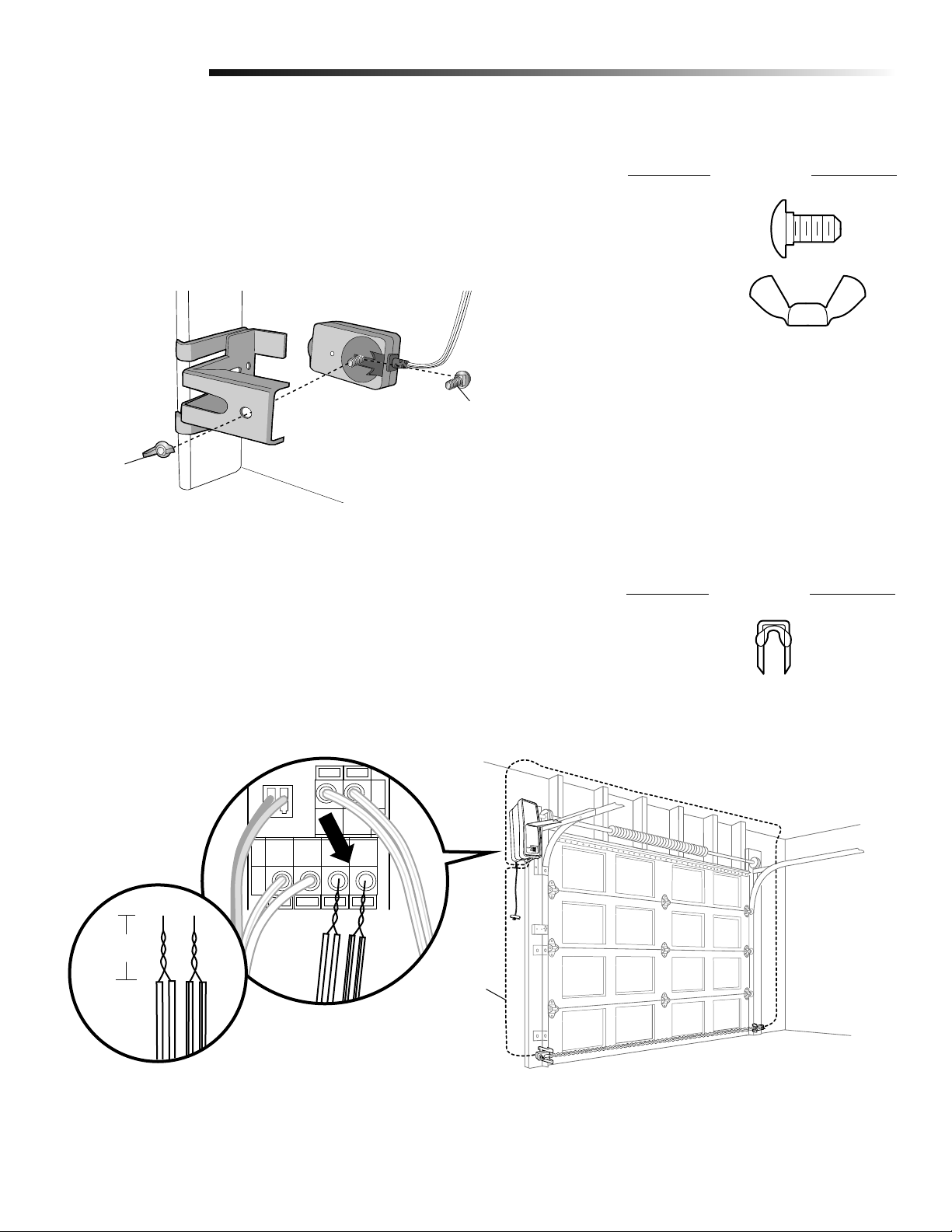
Installation
Attach the Cable Tension Monitor (Required)
4
NOTE: The cable tension monitor is shipped for left side installation. It is
recommended that the cable tension monitor be installed on the same side of the
door as the garage door opener. For right side installation, remove the snap-ring
holding the roller in place and reassemble it on the opposite side of the cable
tension monitor.
1
Position the cable tension monitor as close to the drum as possible. Make sure cable
tension monitor is located over a wood support member and the roller is free from
any obstructions.
NOTE: There must be no obstructions in the installation area that prevent the cable
tension monitor or the cable itself from closing completely when slack is detected.
Mark and drill 3/16 inch pilot holes for screws (pilot holes are not required
2
for anchors).
NOTE: If the cable tension monitor cannot be mounted into wood with the lag screws
provided, it can be mounted into 1/2 inch or greater drywall using the wall anchors
(2) and the #8 hex screws (2) provided in the hardware bag.
Attach the cable tension monitor to the wall using the hardware provided. Make sure
3
that the roller is on top of the cable.
Run bell wire to garage door opener. Use insulated staples to secure wire.
4
Connect bell wire to the green quick-connect terminals on the garage door opener
5
(polarity is not important).
NOTE: Cable must have tension through entire door travel. Make sure there is no
slack in cable on opposite side of garage door during normal operation. If slack
occurs during door travel, adjust cables as required.
The cable tension monitor MUST be connected
and properly installed before the garage door
opener will move in the down direction.
The cable tension monitor detects ANY slack
that may occur in the cables and will reverse
the door, eliminating service calls.
HARDWARE
#8 Hex Head Screw (2)
Screw #6 (2)
Wall Anchor (2)
Staples
To insert or release
wire, push in tab
with screwdriver tip
5
Strip wire 7/16" (11 mm)
WHT/GRN
From cable
tension monitor
To garage door
garage door opener
1/8"-1/4"
(3-6 cm)
Cable
SIDE VIEW
Drum
4
Wall
3
2"-6"
(5-15 cm)
1
Cable
Tension
Monitor
3/4" Min.
(18 cm Min.)
3
2
Cable Tension
Monitor Roller
10
Page 11
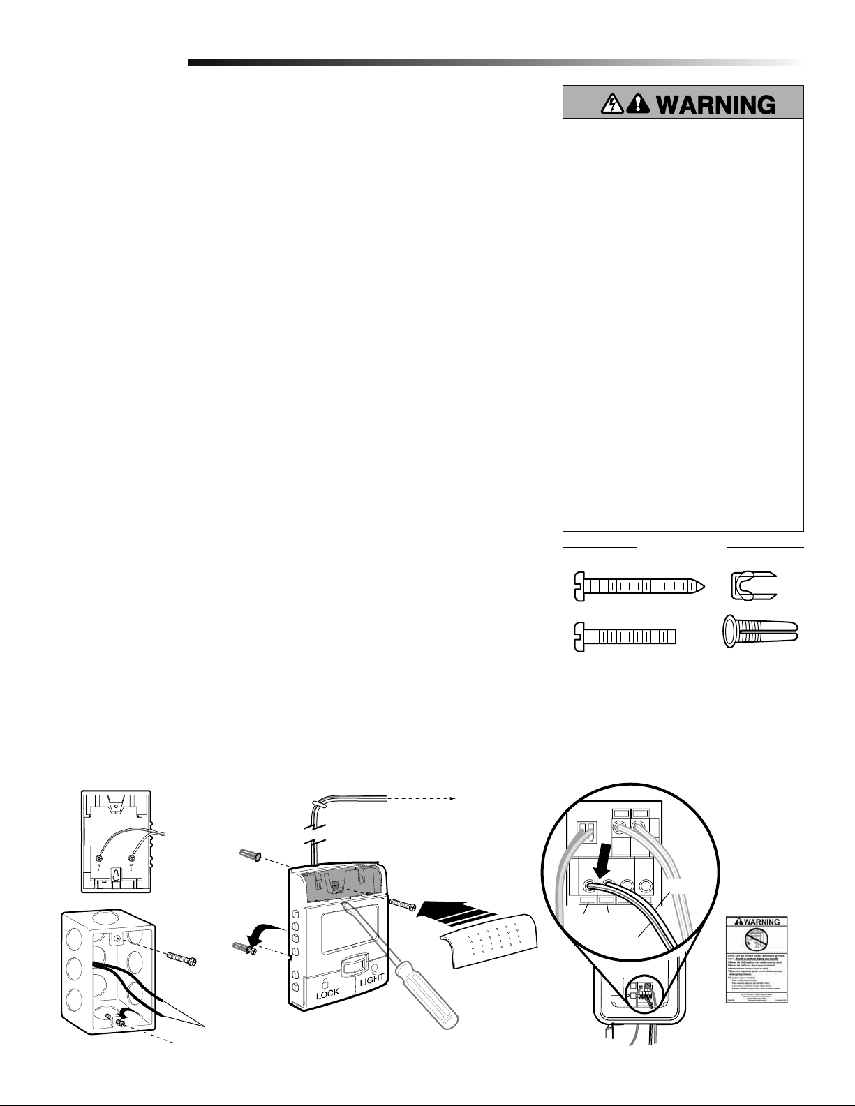
Installation
Install the Smart Control Panel
5
Locate door control within sight of door, at a minimum height of 5 feet (1.5 m) where small
children cannot reach, away from moving parts of door and door hardware.
If installing into drywall, drill 5/32 inch holes and use the anchors provided. For pre-wired
installations (as in new home construction), control panel may be mounted to a single
gang box.
NOTE: The functional temperature range of the door control is between -4° F (-20° C) and
122° F (50° C). Scroll speed of display is slower at lower temperatures although the door
control remains fully functional.
CAUTION: Continuous exposure of the door control to temperatures below -22° F (-30° C)
may damage the LCD screen.
SPECIAL NOTE: Only one Smart Control Panel® can be connected to each garage door
opener. If additional door controls are desired to operate the same garage door opener, it
is recommended to use model 378LM wireless door control as the secondary door control.
Strip 7/16 inch (11 mm) of insulation from one end of bell wire and connect to the
1
two screw terminals on back of door control: white wire to W(2) and white/red wire
to R(1).
Remove push bar cover by gently prying at the lower/middle portion of the cover with
2a
a small fl at-head screwdriver. Fasten with 6AB x 1-1/4" self-tapping screws (drywall
installation) or 6-32 x 1" machine screws (into gang box) as follows:
Install bottom screw, allowing 1/8 inch (3 mm) to protrude above wall surface.
b
Position bottom of door control on screw head and slide down to secure. Adjust
c
screw for snug fi t.
d
Install top screw with care to avoid cracking plastic housing. DO NOT overtighten.
Replace cover by inserting top tabs fi rst and then snap cover in place.
e
®
To prevent possible SERIOUS INJURY
or DEATH from electrocution:
• Be sure power is NOT connected
BEFORE installing door control.
• Connect ONLY to 24 VOLT low voltage
wires.
To prevent possible SERIOUS INJURY
or DEATH from a closing garage door:
• Install door control within sight of
garage door, out of reach of children
at a minimum height of 5 feet
(1.5 m) and away from ALL moving
parts of door.
• NEVER permit children to operate or
play with door control push buttons or
remote controls.
• Activate door ONLY when it can be
seen clearly, is properly adjusted and
there are no obstructions to door
travel.
• ALWAYS keep garage door in sight
until completely closed. NEVER permit
anyone to cross path of closing
garage door.
HARDWARE
(For standard installations ONLY) Run bell wire up wall and across ceiling to the
3
garage door opener. Use insulated staples to secure wire in several places. DO NOT
pierce wire with a staple, creating a short or open circuit.
4
Strip 7/16 inch (11 mm) of insulation from end of bell wire. Connect bell wire to the
quick-connect terminals on the garage door opener: white to white and white/red
to red.
5
Fasten the warning placard to the wall next to the door control.
NOTE: If you have any trouble with the operation of the buttons, loosen the top
mounting screw. DO NOT connect the power and operate the garage door opener at
this time. The door will travel to the full open position but will not return to the close
position until the sensor beams are connected and properly aligned. See page 15.
To garage
3
door opener
1
2
Screw 6ABx1-1/4"
(standard installation)
Screw 6-32x1"(pre-wired)
Red White
WHT/RED
WHT
4
Insulated Staples
Drywall Anchors
To insert or release
wire, push in tab
with screwdriver tip
24V Bell Wire
5
(Fasten next to
door control)
11
Page 12
Installation
IMPORTANT INSTALLATION INSTRUCTIONS
To reduce the risk of SEVERE INJURY or DEATH:
1. This portable luminaire has a polarized plug (one blade
is wider than the other) as a feature to reduce the risk of
electric shock.
2. This plug will fi t in a polarized outlet ONLY one way.
3. If the plug does not fi t fully in the outlet, reverse the plug.
4. If it still does not fi t, contact a qualifi ed electrician.
WARNING
5. NEVER use with an extension cord unless plug can be
fully inserted.
6. DO NOT alter the plug.
7. Light is intended for ceiling mount and indoor applications
ONLY.
Install Remote Light
6
The remote light (garage door opener light)
is designed to plug directly into a standard
120V outlet. Select an appropriate location
on the ceiling to mount the light within 6
feet (1.8 m) of an electrical outlet so that
the cord and light are away from moving
parts.
Install the hinge and latch clips. Clips
1
slide in between the metal plate and
the plastic housing on each side of the
light base.
Install screws into the ceiling leaving
2
1/8 inch (3.1 mm) of the thread
exposed.
NOTE: If installing light on drywall and
a ceiling joist cannot be located, use
wall anchors provided. No pilot hole is
required for wall anchors.
Determine the length of power cord
3
needed to reach the nearest outlet.
Wind any excess cord around cord
retainer on the top side of the light
base.
Install the light base by pushing onto
4
the screws and turning the base
clockwise to lock the light in place.
Wall Anchor (2)
Light Clip Screw
#4-20x7/16" (2)
Screw
#6x1" (2)
3
Cord
Retainer
Latch Clip
HARDWARE
To prevent possible OVERHEATING of
the endpanel or light socket:
• DO NOT use short neck or specialty
light bulbs.
• DO NOT use halogen bulbs. Use
ONLY incandescent.
To prevent damage to the opener:
• DO NOT use bulbs larger than 100W.
• ONLY use A19 size bulbs.
Wall Anchor
4
1
Install two Type A19 incandescent or
5
compact fl uorescent bulbs. 100 watt
maximum per bulb, 200 watts total.
Install the light lens by hooking one
6
end of the lens over the hinge and
pressing up on the other end to latch
into place.
Plug in the light to outlet.
7
NOTE: Light will not operate until the
garage door opener is activated.
Plastic
Housing
Metal
Plate
12
2
Screws
Light Clip
Screw
5
100 Watt
(max.)
6
Hinge Clip
1
Light Lens
Page 13
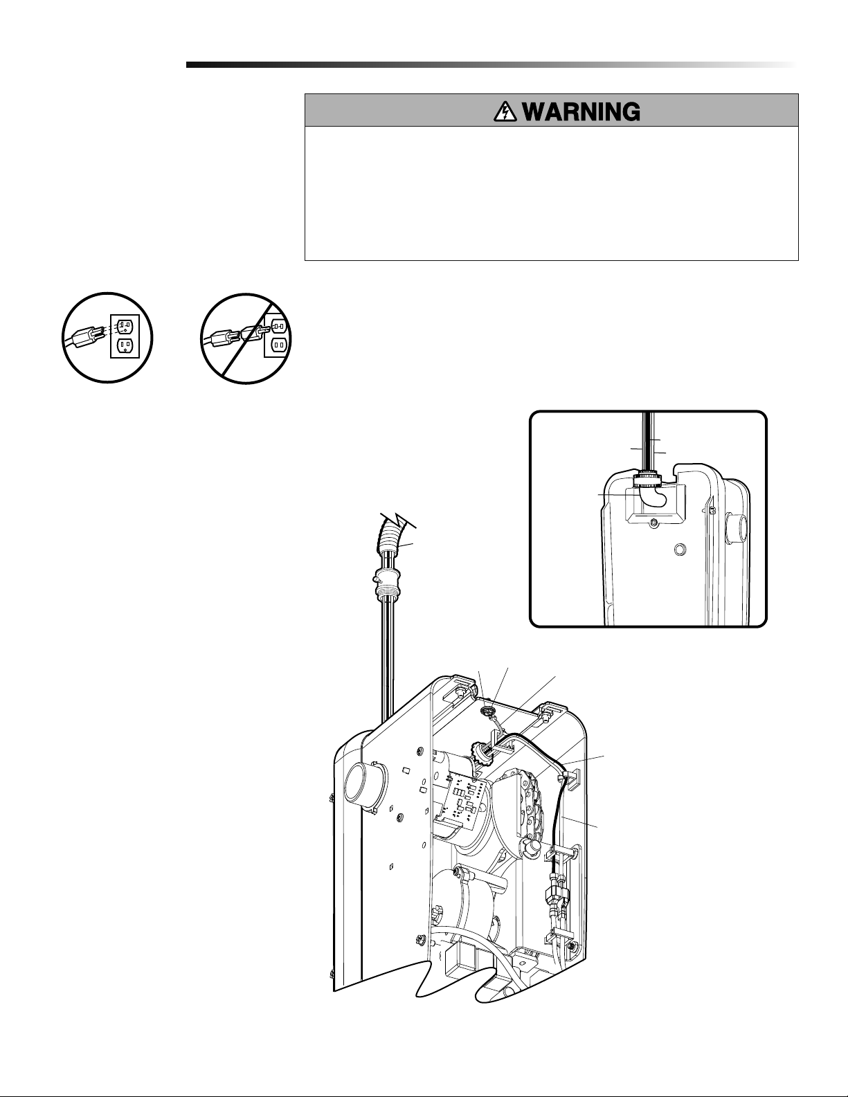
Installation
90˚ Connector
Green Wire
White Wire
Black Wire
Electrical Requirements
7
To avoid installation diffi culties, do not run
the garage door opener at this time.
To reduce the risk of electric shock, your
garage door opener has a grounding type
plug with a third grounding pin. This plug
will only fi t into a grounding type outlet. If
the plug doesn't fi t into the outlet you have,
contact a qualifi ed electrician to install the
proper outlet.
RIGHT WRONG
PERMANENT WIRING CONNECTION
If permanent wiring is required by your local
code, refer to the following procedure.
To make a permanent connection through
the 7/8 inch hole in the back of the garage
door opener (according to local code):
To prevent possible SERIOUS INJURY or DEATH from electrocution or fi re:
• Be sure power is NOT connected to the opener, and disconnect power to circuit
BEFORE removing cover to establish permanent wiring connection.
• Garage door installation and wiring MUST be in compliance with ALL local electrical
and building codes.
• NEVER use an extension cord, 2-wire adapter or change plug in ANY way to make it
fi t outlet. Be sure the opener is grounded.
Remove the garage door opener from
1
the torsion bar, remove cover screws
and set the cover aside.
Remove the attached green ground
2
terminal.
Cut black and white wires and strip
3
away 1/2 inch (1.3 cm) of insulation,
3 inch (7.6 cm) before spade
terminals.
Remove the power cord from the
4
garage door opener.
Install a 90° conduit or fl ex cable
5
adapter to the 7/8 inch hole. Reinstall
garage door opener to torsion bar.
Run wires through conduit, cut to
6
proper length and strip insulation.
Attach with wire nuts provided.
7
Properly secure wire under plastic ties
8
so that wire does not come in contact
with moving parts.
Reinstall the cover.
9
To avoid installation diffi culties, do not run
the garage door opener at this time.
Flexible Conduit
Ground Tab
Green
Ground
Screw
Back View
Ground Wire
Black Wire
from power cord
White Wire
from power cord
13
Page 14
Installation
Install the EverCharge® Standby Power System (SPS)
8
(optional)
®
If the optional EverCharge
installed at this time. The SPS can be mounted to either the ceiling or a wall within 3 feet
(.9 m) of the garage door opener.
Position the SPS on a structural support (ceiling joist or wall stud).
1
Attach the SPS to the support with the 1-1/2 inch lag screws (2) provided. There are
2
mounting holes on either side of the SPS.
Connect the SPS cord into the connector on the bottom of the garage door opener.
3
Follow all instructions included with the EverCharge® Standby Power System to test
4
for proper operation.
Standby Power System is part of this installation it should be
EverCharge
Power System
®
Standby
Wall Anchor
SPU Cord
Connector
14
Page 15
Installation
Install the Protector System
9
The safety reversing sensor must be connected and aligned correctly before the garage door
opener will move in the down direction. This is a required safety device and cannot be disabled.
®
IMPORTANT INFORMATION ABOUT THE SAFETY REVERSING SENSOR
When properly connected and aligned, the safety reversing sensor will detect an obstacle
in the path of its electronic beam. The sending eye (with an amber indicator light)
transmits an invisible light beam to the receiving eye (with a green indicator light). If an
obstruction breaks the light beam while the door is closing, the door will stop and reverse
to full open position, and the opener lights will fl ash 10 times.
The units must be installed inside the garage so that the sending and receiving eyes face
each other across the door, no more than 6 inches (15 cm) above the fl oor. Either can be
installed on the left or right of the door as long as the sun never shines directly into the
receiving eye lens.
The mounting brackets are designed to clip onto the track of sectional garage doors
without additional hardware.
If it is necessary to mount the units on the wall, the brackets must be securely fastened to
a solid surface such as the wall framing. Extension brackets (see accessories) are available
if needed. If installing in masonry construction, add a piece of wood at each location to
avoid drilling extra holes in masonry if repositioning is necessary.
The invisible light beam path must be unobstructed. No part of the garage door (door
tracks, springs, hinges, rollers or other hardware) may interrupt the beam while the door
is closing.
Be sure power is NOT connected to the
garage door opener BEFORE installing
the safety reversing sensor.
To prevent SERIOUS INJURY or DEATH
from a closing garage door:
• Correctly connect and align the
safety reversing sensor. This
required safety device MUST NOT be
disabled.
• Install the safety reversing sensor so
beam is NO HIGHER than 6" (15 cm)
above garage fl oor.
Safety Reversing Sensor
6" (15 cm) max. above floor
Invisible Light Beam
Protection Area
Facing the door from inside the garage.
Safety Reversing Sensor
6" (15 cm) max. above floor
15
Page 16
Installation
INSTALLING THE BRACKETS
Be sure power to the opener is disconnected. Install and align the brackets so the safety reversing sensors will face each other across
the garage door, with the beam no higher than 6" (15 cm) above the fl oor. They may be installed in one of three ways, as follows.
Track Installation
1a
1. Slip the curved arms over the
rounded edge of each door track,
with the curved arms facing the
door. Snap into place against the
side of the track. It should lie fl ush,
with the lip hugging the back edge
of the track, as shown.
If your door track will not support the
bracket securely, wall installation is
recommended.
Door Track
Safety Reversing
Sensor Bracket
Wall Installation
1b
1. Place the bracket against the
wall with curved arms facing the
door. Be sure there is enough
clearance for the sensor beam to be
unobstructed.
2. If additional depth is needed, an
extension bracket (see Accessories)
or wood blocks can be used.
3. Use bracket mounting holes as a
template to locate and drill (2) 3/16"
diameter pilot holes on the wall at
each side of the door, no higher
than 6" (15 cm) above the fl oor.
4. Attach brackets to wall with
lag screws (not provided).
If using extension brackets or wood
blocks, adjust right and left assemblies
to the same distance out from the
mounting surface. Make sure all door
hardware obstructions are cleared.
Floor Installation
1c
1. Use wood blocks or extension
brackets (see Accessories) to
elevate sensor brackets so the
lenses will be no higher than 6"
(15 cm) above the fl oor.
2. Carefully measure and place right
and left assemblies at the same
distance out from the wall. Be sure
all door hardware obstructions are
cleared.
3. Fasten to the fl oor with concrete
anchors as shown.
Attach with
Concrete Anchors
(not provided)
Safety Reversing
Sensor Bracket
(Provided with
Extension Bracket)
Fasten Wood Block to Wall with
Lag Screws (not provided)
Safety Reversing
Sensor Bracket
Lag Screws
(not provided)
Extension Bracket
(See Accessories)
(Provided with
Extension Bracket)
Safety Reversing
Sensor Bracket
16
Page 17
Installation
MOUNTING AND WIRING THE SAFETY REVERSING SENSORS
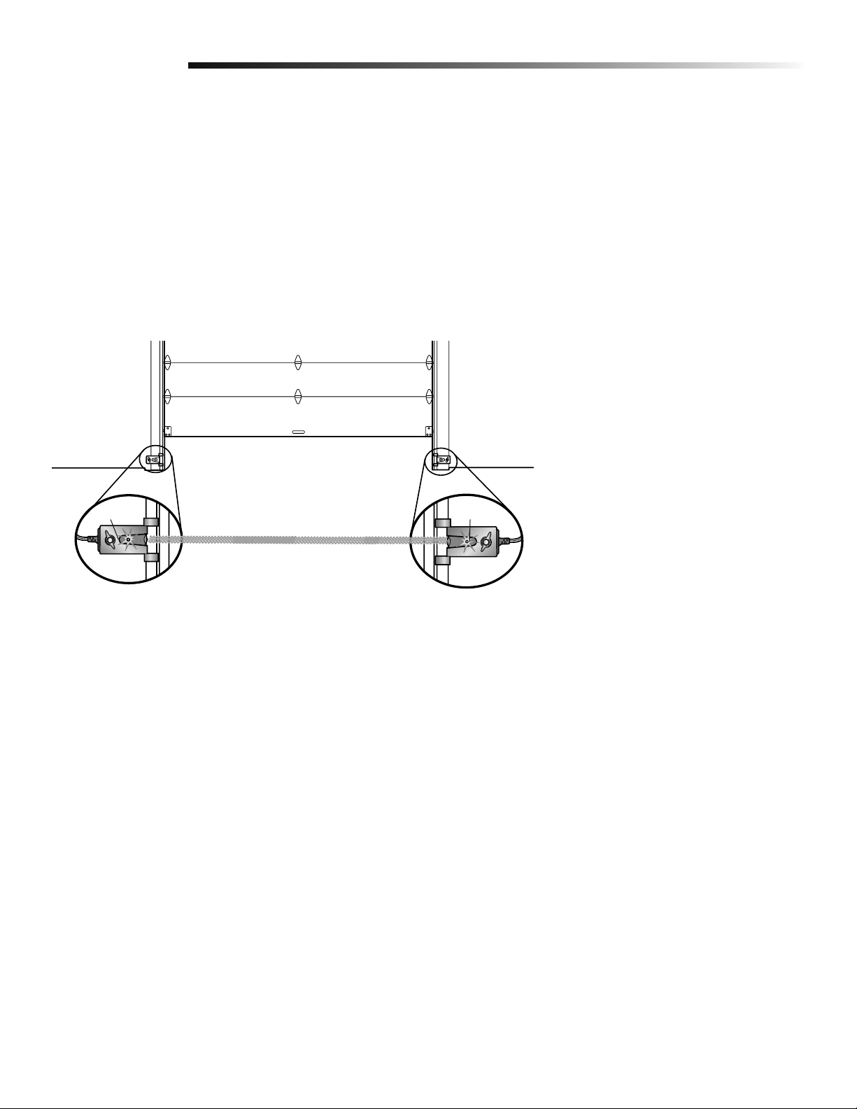
Slide a 1/4"-20x1/2" carriage bolt head into the slot on each sensor.
1
Use wing nuts to fasten safety reversing sensors to brackets, with lenses pointing
2
toward each other across the door. Be sure the lens is not obstructed by a bracket
extension.
Finger tighten the wing nuts.
3
Carriage Bolt
Wing Nut
HARDWARE
Carriage Bolt
1/4"-20x1/2"
Wing Nut
1/4"-20
Run the wires from both safety reversing sensors to the opener. Use insulated staples
4
to secure wire to wall and ceiling.
Strip 7/16" (11 mm) of insulation from each set of wires. Separate white and white/
5
black wires suffi ciently to connect to the opener quick-connect terminals: white to
white and white/black to grey.
7/16
(11 mm)
WHITE
WHITE/
BLACK
Bell wire
HARDWARE
Staple
17
Page 18
Installation
ALIGNING THE SAFETY REVERSING SENSORS
Plug in the opener. The indicator lights in both the sending and receiving eyes will
1
glow steadily if wiring connections and alignment are correct.
The sending eye amber indicator light will glow regardless of alignment or
obstruction. If the green indicator light in the receiving eye is off, dim, or fl ickering
(and the invisible light beam path is not obstructed), alignment is required.
Loosen the sending eye wing nut and readjust, aiming directly at the receiving eye.
2
Lock in place.
Loosen the receiving eye wing nut and adjust the safety reversing sensor until it
3
receives the sender’s beam. When the green indicator light glows steadily, tighten the
wing nut.
Amber LED
Sending Sensor
Green LED
Receiving Sensor
TROUBLESHOOTING THE SAFETY REVERSING SENSORS
If the sending eye indicator light does not glow steadily after installation, check for:
1
• Electric power to the opener.
• A short in the white or white/black wires. These can occur at staples, or at opener
connections.
• Incorrect wiring between safety reversing sensors and opener.
• A broken wire.
If the sending eye indicator light glows steadily but the receiving eye indicator light
2
doesn't:
• Check a lignment.
• Check for an open wire to the receiving eye.
If the receiving eye indicator light is dim, realign either sensor.
3
NOTE: When the invisible beam path is obstructed or misaligned while the door is
closing, the door will reverse. If the door is already open, it will not close.
The remote lights will blink 10 times. (If bulbs are not installed, 10 clicks can be
heard.) See page 15.
18
Page 19
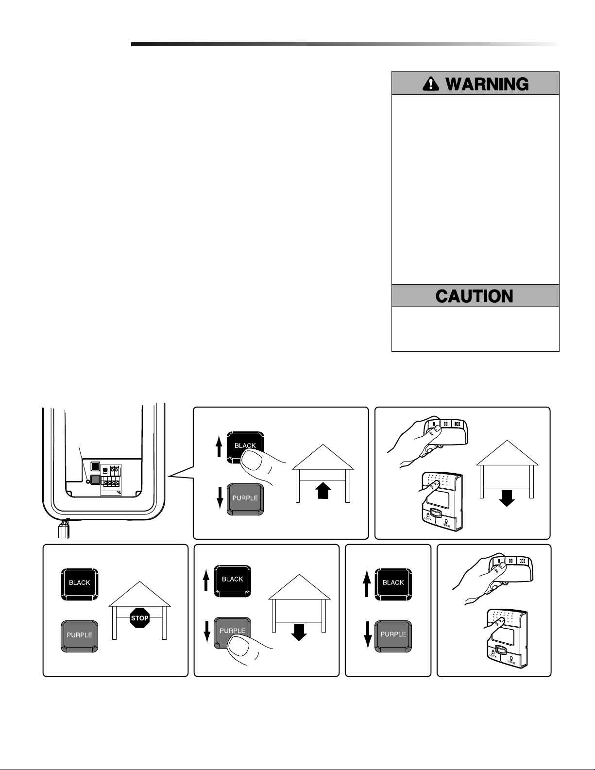
Adjustment
Program the Travel Limits
1
Travel limits regulate the points at which the door will stop when moving up or down.
Adjust the position of the door by using the black and purple buttons. Black moves the
door UP (open) and purple moves the door DOWN (close).
SETTING THE UP POSITION:
Press and hold the black button until the LED starts fl ashing slowly, then release.
1
Push and hold the black button until the door reaches the desired UP (open) position.
2
NOTE: Make sure the door opens high enough for your vehicle.
Push the door control or programmed remote control. This sets the UP (open) limit
3
and begins closing the door.
Immediately when the door begins to close, press and release either the black or
4
purple button. This will stop the door.
SETTING THE DOWN POSITION:
Push and hold the purple button until the door reaches the desired DOWN (closed)
5
position.
Once the door is closed, if there appears to be too much pressure on the door, you
6
may toggle the door back and forth using the black and purple buttons to reach the
desired closed position.
Push the door control or programmed remote control. This sets the DOWN (close)
7
limit and the door should open.
Proceed to Set the Force.
Without a properly installed safety
reversal system, persons (particularly
small children) could be SERIOUSLY
INJURED or KILLED by a closing
garage door.
• NEVER learn forces or limits when
door is binding or sticking. Repair
door fi rst.
• Incorrect adjustment of garage door
travel limits will interfere with proper
operation of safety reversal system.
• After ANY adjustments are made,
the safety reversal system MUST
be tested. Door MUST reverse on
contact with 1-1/2" high (3.8 cm)
object (or 2x4 laid fl at) on fl oor.
To prevent damage to vehicles, be
sure fully open door provides adequate
clearance.
or
1
LED
2
3
or
7456
or
19
Page 20
Adjustment
Set the Force
2
The force setting measures the amount of force required to open and close the door.
Push the purple button twice to enter into the Force Adjustment Mode. The LED will
1
fl ash quickly.
Push the door control or programmed remote control. The door will close (DOWN).
2
Push the door control or programmed remote control again. The door will open (UP).
3
Push the door control or programmed remote control a third time to close the
4
door (DOWN).
The LED will stop fl ashing when the force has been programmed.
The door must travel through a complete cycle, up and down, in order for the force to be
set properly. If the garage door opener cannot open and close the door fully, inspect the
door to ensure that it is balanced properly and is not sticking or binding.
If the door is not stopping exactly where you would like it, repeat Program the
Travel Limits.
Without a properly installed safety
reversal system, persons (particularly
small children) could be SERIOUSLY
INJURED or KILLED by a closing
garage door.
• NEVER learn forces or limits when
door is binding or sticking. Repair
door fi rst.
• Too much force on garage door will
interfere with proper operation of
safety reversal system.
• After ANY adjustments are made,
the safety reversal system MUST
be tested. Door MUST reverse on
contact with 1-1/2" high (3.8 cm)
object (or 2x4 laid fl at) on fl oor.
LED
1
Push Purple button
twice to enter garage
door opener into
Force Adjustment
Mode
423
or or or
20
Page 21
Adjustment
Test the Safety Reversal System
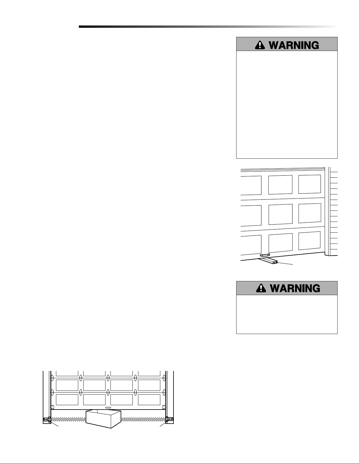
3
TEST
With the door fully open, place a 1-1/2 inch (3.8 cm) board (or a 2x4 laid fl at) on the fl oor,
centered under the garage door.
Operate the door in the down direction. The door must reverse on striking the obstruction.
Upon successful safety reversal test proceed to Adjustment Step 4.
ADJUST
If the door stops on the obstruction, it is not traveling far enough in the down direction.
Complete Adjustment Steps 1 and 2 Program the Travel Limits and Set the Force.
Repeat the test.
When the door reverses on the 1-1/2 inch (3.8 cm) board (or 2x4 laid fl at), remove the
obstruction and run the garage door opener through 3 or 4 complete travel cycles to
test adjustment.
If the garage door opener continues to fail the Safety Reverse Test, call for a trained door
systems technician.
IMPORTANT SAFETY CHECK:
Test the Safety Reverse System after:
• Each adjustment of limits, or force controls.
Without a properly installed safety
reversal system, persons (particularly
small children) could be SERIOUSLY
INJURED or KILLED by a closing
garage door.
• Safety reversal system MUST be
tested every month.
• If one control (force or travel limits) is
adjusted, the other control may also
need adjustment.
• After ANY adjustments are made,
the safety reversal system MUST be
tested. Door MUST reverse on contact
with 1-1/2" (3.8 cm) high object (or
2x4 laid fl at) on the fl oor.
• Any repair to or adjustment of the garage door (including springs and hardware).
• Any repair to or buckling of the garage fl oor.
• Any repair to or adjustment of the opener.
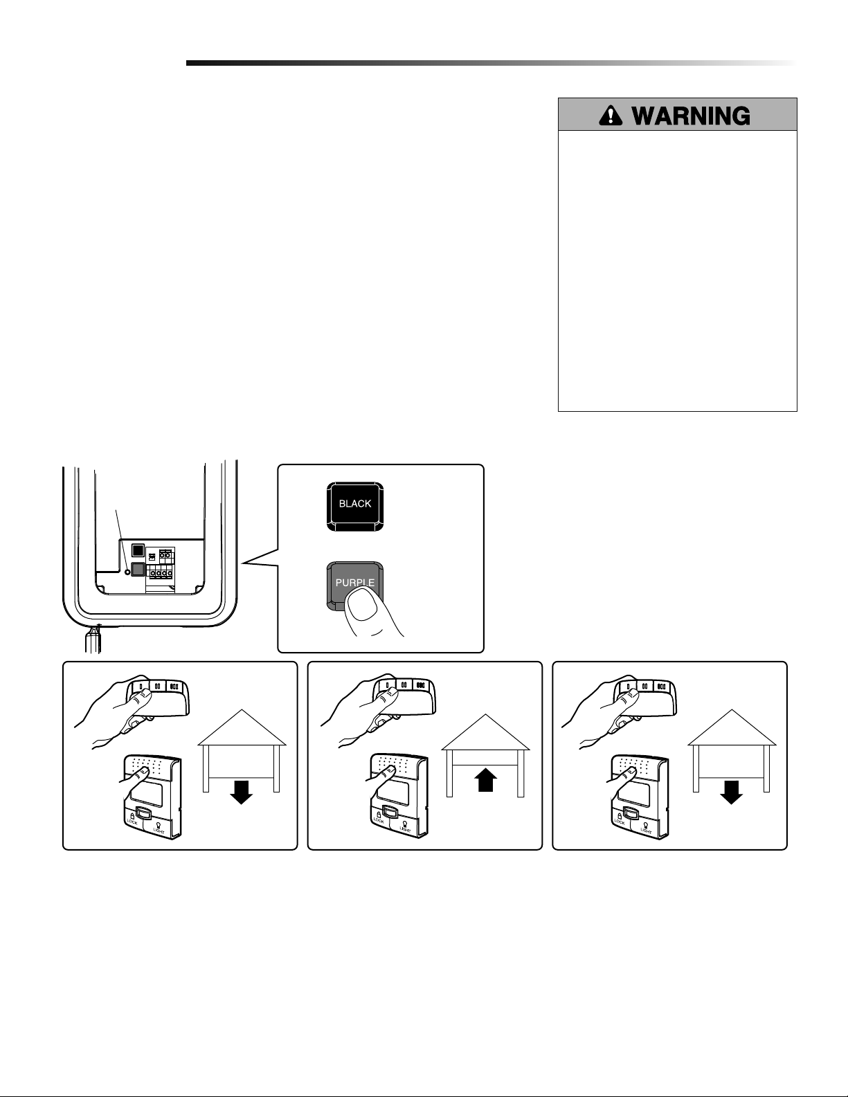
Test the Protector System
4
• Press the remote control push button to open the door.
• Place the opener carton in the path of the door.
• Press the remote control push button to close the door. The door will not move more
than an inch, and the opener lights will fl ash.
The garage door opener will not close from a remote if the indicator light in either sensor
is off (alerting you to the fact that the sensor is misaligned or obstructed).
If the garage door opener closes the door when the safety reversing sensor is obstructed, do
not operate the door. Call for a trained door systems technician.
®
1-1/2" (3.8 cm) board
(or a 2x4 laid flat)
Without a properly installed safety
reversing sensor, persons (particularly
small children) could be SERIOUSLY
INJURED or KILLED by a closing
garage door.
Safety Reversing Sensor
Safety Reversing Sensor
21
Page 22
Adjustment
Test Cable Tension Monitor
5
If your cable tension monitor has been
activated the LED on the garage door
opener will blink 9 times.
Test Power Door Lock
6
1. With the door fully closed, the power
door lock bolt should be protruding
through the track.
2. Operate the door in the open direction.
The power door lock should retract
before the door begins to move.
3. Operate the door in the down direction.
When the door reaches the fully closed
position, the power door lock should
automatically activate to secure the
door.
NOTE: If the power door lock does
not function, the lock can be manually
released by sliding the manual release
handle to the open position.
LED
To prevent possible SERIOUS INJURY
or DEATH from a falling garage door:
• If possible, use emergency release
handle to disengage door ONLY when
garage door is CLOSED. Weak or
broken springs or unbalanced door
could result in an open door falling
rapidly and/or unexpectedly.
• NEVER use emergency release handle
unless garage doorway is clear of
persons and obstructions.
Power Door Lock
Manual Release
Lock Bolt
“Locked”
To Open the Door Manually
7
Disengage door lock before proceeding.
The door should be fully closed if possible.
Pull down on the emergency release handle
until a click noise is heard from the garage
door opener and lift the door manually.
To reconnect the door to the garage door
opener, pull the emergency release handle
straight down a second time until a click
noise is heard from the garage door
opener. The door will reconnect on the next
UP or DOWN operation.
Test the emergency release:
1. Make sure the garage door is closed.
2. Pull the emergency release handle. The
garage door should then be able to be
opened manually.
3. Return the door to the closed position.
4. Pull the emergency handle a second
time.
5. Reconnect the door to the garage door
opener.
Emergency
Release Handle
22
Page 23

Operation
IMPORTANT INSTALLATION INSTRUCTIONS
WARNING
To reduce the risk of SEVERE INJURY or DEATH:
1. READ AND FOLLOW ALL WARNINGS AND INSTRUCTIONS.
2. ALWAYS keep remote controls out of reach of children.
NEVER permit children to operate or play with door control
push buttons or remote controls.
3. ONLY activate door when it can be seen clearly, it is
properly adjusted and there are no obstructions to door
travel.
4. ALWAYS keep door in sight until completely closed. NO
ONE SHOULD CROSS THE PATH OF THE MOVING DOOR.
5. NO ONE SHOULD GO UNDER A STOPPED, PARTIALLY
OPENED DOOR.
6. If possible, use emergency release handle to disengage door
ONLY when door is CLOSED. Weak or broken springs or
unbalanced door could result in an open door falling rapidly
and/or unexpectedly, causing SEVERE INJURY or DEATH.
7. NEVER use emergency release handle unless doorway is
clear of persons and obstructions.
8. After ANY adjustments are made, the safety reversal
system MUST be tested. Failure to adjust the garage door
opener properly may cause SEVERE INJURY or DEATH.
9. Safety reversal system MUST be tested every month. Door
MUST reverse on contact with 1-1/2" (3.8 cm) high object
(or a 2x4 laid flat) on the floor. Failure to adjust the garage
door opener properly may cause SEVERE INJURY or
DEATH.
10. ALWAYS KEEP DOOR PROPERLY BALANCED (see
page 3). An improperly balanced door may not reverse
when required and could result in SEVERE INJURY or
DEATH.
11. ALL repairs to cables, spring assemblies and other
hardware, ALL of which are under EXTREME tension,
MUST be made by a trained door systems technician.
12. ALWAYS disconnect electric power to garage door opener
BEFORE making ANY repairs or removing covers.
13.
SAVE THESE INSTRUCTIONS.
Using Your Garage Door Opener
Your Security✚® garage door opener
and hand-held remote control have
been factory-set to a matching code
which changes with each use, randomly
accessing over 100 billion new codes. Your
garage door opener will operate with up
to eight Security✚® remote controls and
one Security✚® Keyless Entry System.
If you purchase a new remote, or if you
wish to deactivate any remote, follow the
instructions in the Programming section.
Activate your garage door opener with any
of the following:
• The hand-held Remote Control: Hold the
large push button down until the door
starts to move.
• The wall-mounted Door Control: Hold the
push button or bar down until the door
starts to move.
• The Keyless Entry (See Accessories): If
provided with your garage door opener,
it must be programmed before use. See
Programming.
When the garage door opener is activated
(with the safety reversing sensor correctly
installed and aligned).
• If open, the door will close. If closed, it
• If closing, the door will reverse.
• If opening, the door will stop.
• If the door has been stopped in a partially
• If obstructed while closing, the door will
• If obstructed while opening, the door
• If fully open, the door will not close when
will open.
open position, it will close.
reverse. If the obstruction interrupts the
sensor beam, the garage door opener
lights will blink for fi ve seconds.
will stop.
the beam is broken. The sensor has no
effect in the opening cycle.
If the sensor is not installed, or is
misaligned, the door won’t close from a
hand-held remote. However, you can close
the door with the Door Control, the Outside
Keylock, or Keyless Entry, if you activate
them until down travel is complete. If
you release them too soon, the door will
reverse.
The garage door opener lights will turn on
when the garage door opener is activated.
They will turn off automatically after 4-1/2
minutes or provide constant light when the
Light feature on the Smart Control Panel
is activated. Bulb size is A19. Bulb power is
100 watts maximum.
Security✚® light feature: Lights will also
turn on when someone walks through the
open garage door. With a Smart Control
Panel®, this feature may be turned off as
follows: With the garage door opener lights
off, press and hold the light button for 10
seconds, until the light goes on, then off
again. To restore this feature, start with the
garage door opener lights on, then press
and hold the light button for 10 seconds
until the light goes off, then on again.
®
23
Page 24

Operation
Using the Smart Control Panel
®
Press the push bar to open or close the
door. Press again to reverse the door
during the closing cycle or to stop the door
while it's opening.
This door control contains a motion
sensing detector that will automatically
turn on the light when it detects a person
entering the garage.
Light feature
Press the Light button to turn the garage
door opener light on or off. It will not
control the garage door opener lights when
the door is in motion. If you turn it on and
then activate the garage door opener, the
light will remain on for 4-1/2 minutes.
Press again to turn it off sooner. The 4-1/2
minute interval can be changed to 1-1/2,
2-1/2, or 3-1/2 minutes as follows: Press
and hold the Lock button until the light
blinks (about 10 seconds). A single blink
indicates that the timer is reset to 1-1/2
minutes. Repeat the procedure and the
light will blink twice, resetting the timer to
2-1/2 minutes. Repeat again for a 3-1/2
minute interval, etc., up to a maximum of
four blinks and 4-1/2 minutes. When using
the garage door opener lights as working
lights, we recommend that you fi rst disable
the motion sensor. See Automatic Light
Feature, below.
Motion Sensing (Automatic Light
Feature)
The garage door opener light will turn on
automatically when a person enters the
garage. When a person walks in front of the
door control, the light will come on for fi ve
minutes, then shut off. This feature works
by detecting body heat.
To disable this feature, push the motion
sensing button on the side of the door
control.
We recommend that you disable the motion
sensor when using the garage door opener
lights as working lights. Otherwise, they
will turn off automatically if you are working
beyond the sensors range.
Motion Sensing
On/Off
Prog <Learn>
Hour
Minute
Language
Degrees (F/C)
Lock feature
Designed to prevent operation of the door
from hand-held remote controls. However,
the door will open and close from the
Door Control, the Outdoor Key Switch
and the Keyless Entry Accessories. To
activate, press and hold the Lock button
for 2 seconds. To turn off, press and hold
the Lock button again for 2 seconds. The
Lock feature will also turn off whenever the
“learn” button on the garage door opener
panel is activated.
(PROG) Learn Feature
The door control is equipped with a Prog
<LEARN> button to assist in learning
remote controls to the garage door opener.
Press the Prog <LEARN> button once to
initiate LEARN mode and the display will
show ‘Learn Remote Control - Press Learn
Button Again to Confi rm’. Press the Prog
<LEARN> button a second time and the
display will show ‘Learn Mode - Press
Remote Control Button to Learn Remote.’
Press the button of the remote control
to be learned and the worklight will blink
to confi rm the remote control has been
learned.
Hour & Minute Feature
Press or hold either of these side buttons to
increment the hour or minute displayed on
the LCD display.
Push
Bar
Light
Button
Lock Button
(LANG) Language Feature
Press this side button to toggle between
the three languages - English, French and
Spanish.
Degrees F/C Feature
Press this side button to toggle the
temperature units between Fahrenheit and
Celsius.
Display Contrast Adjustment
Press and hold the light button then push
the hour button to increase the contrast or
the minute button to decrease the contrast.
24
Page 25

Operation
Using the Remote Control
Press and hold the button down until
the door or gate starts to move. The
remote control will operate from up to 3
car lengths away on typical installations.
Installations and conditions vary, contact
an installing dealer for more information.
3-Button Remote Controls
Additional buttons on the remote control
can be programmed to operate up to 3
devices such as additional garage door
openers, light controls, gate operators or
access control systems.
To Control the Opener Lights
Additional buttons on the remote control
can be programmed to operate the garage
door opener lights without opening the
door.
1. With the door closed, press and hold the
remote button that you want to control
the light.
2. Press and hold the Light button on the
Smart Control Panel®.
3. Press and hold the Lock button on the
Smart Control Panel®.
4. After the opener lights fl ash, release all
buttons.
Test by pressing the remote push button.
The opener lights should turn on or off but
the door should not move.
The Remote Control Battery
The LED(s) on your remote control will stop fl ashing when the battery is low and needs
to be replaced. To replace battery, open the case as shown. Insert battery positive side
up (+). Replace the battery with only 3V2016 coin cell batteries. Dispose of old battery
properly.
Remove the two screws
and open the case.
3V2016
To prevent possible SERIOUS INJURY
or DEATH:
• NEVER allow small children near
batteries.
• If battery is swallowed, immediately
notify doctor.
To reduce risk of fi re, explosion or
chemical burn:
• Replace ONLY with 3V2016 coin
batteries.
• DO NOT recharge, disassemble, heat
above 100° C (212° F) or incinerate.
NOTICE: To comply with FCC and or Industry Canada (IC)
rules, adjustment or modifications of this receiver and/or
transmitter are prohibited, except for changing the code
setting or replacing the battery. THERE ARE NO OTHER
USER SERVICEABLE PARTS.
Tested to Comply with FCC Standards FOR HOME OR
OFFICE USE. Operation is subject to the following two
conditions: (1) this device may not cause harmful
interference, and (2) this device must accept any
interference received, including interference that may
cause undesired operation.
25
Page 26

Operation
Care of Your Garage Door Opener
MAINTENANCE SCHEDULE
Once a Month
• Manually operate door. If it is unbalanced or binding, call a trained door systems technician.
• Check to be sure door opens & closes fully. Adjust limits and/or force if necessary (see Adjustment Steps 1 and 2).
• Repeat the safety reverse test. Make any necessary adjustments (see Adjustment Step 3).
Once a Year
• Oil door rollers, bearings and hinges. The garage door opener does not require additional lubrication. Do not grease the door tracks.
Troubleshooting
The garage door opener doesn't operate from either the door control or the remote control:
• Does the garage door opener have electric power? Plug a lamp into the outlet. If it doesn't light, check the fuse box or the circuit
breaker. (Some outlets are controlled by a wall switch.)
• Have you disabled all door locks? Review installation instruction warnings on page 7.
• Is there a build-up of ice or snow under the door? The door may be frozen to the ground. Remove any restriction.
• The garage door spring may be broken. Have it replaced (see page 3 for reference).
Garage door opener operates from the remote, but not from the door control:
• Is the door control lit? If not, reverse the wires. If the garage door opener runs, check for a faulty wire connection at the door control,
a short under the staples, or a broken wire.
• Are the wiring connections correct? Review Installation Step 5, page 11.
The door operates from the door control, but not from the remote control:
• Is the door push bar fl ashing? If so, Lock mode is engaged. Make sure it is off by pressing the Lock button for two seconds.
• Program the garage door opener to match the remote control code. (Refer to instructions on the garage door opener panel.) Repeat
with all remote controls.
The remote control has short range:
• Change the location of the remote control in your car.
• Check to be sure the antenna on the side or back panel of the garage door opener extends fully downward.
• Some installations may have shorter range due to a metal door, foil backed insulation, or metal garage siding.
The garage door opens and closes by itself:
• Be sure that all remote control push buttons are off.
• Remove the bell wire from the door control terminals and operate from the remote only. If this solves the problem, the door control is
faulty (replace), or there is an intermittent short on the wire between the door control and the garage door opener.
• Clear memory and re-program all remote controls.
The door doesn't open completely:
• Check power door lock.
• Is something obstructing the door? Is it out of balance, or are the springs broken? Remove the obstruction or repair the door.
26
Page 27

Operation
Troubleshooting (Continued)
The door opens but won't close:
• Check cable tension monitor (see Installation Step 4).
• If the garage door opener lights blink, check the safety reversing sensor (see Installation Step 9).
• If the garage door opener lights don’t blink and it is a new installation (see Adjustment Step 2). For an existing installation, see below.
Repeat the safety reverse test after the adjustment is complete.
The door reverses for no apparent reason and garage door opener lights don’t blink:
• Check cable tension monitor (see Installation Step 4).
• Is something obstructing the door? Pull the emergency release handle. Operate the door manually. If it is unbalanced or binding, call a
trained door systems technician.
• Clear any ice or snow from the garage fl oor area where the door closes.
• Review Adjustment Step 2.
Repeat safety reverse test after adjustments.
The door reverses for no apparent reason and garage door opener lights blink for 5 seconds after reversing:
• Check the safety reversing sensor. Remove any obstruction or align the receiving eye (see Installation Step 9).
The garage door opener strains to operate door:
• The door may be out of balance or the springs may be broken. Close the door and use the emergency release handle to disconnect the
door. Open and close the door manually. A properly balanced door will stay in any point of travel while being supported entirely by its
springs. If it does not, disconnect the garage door opener and call a trained door systems technician.
The garage door opener motor hums briefl y, then won't work:
• The garage door springs may be broken. See above.
• If the problem occurs on the fi rst operation of the garage door opener, door may be locked. Disable the power door lock.
The garage door opener won't operate due to power failure:
• Manually open the power door lock.
• Use the emergency release handle to disconnect the door. The door can be opened and closed manually. When power is restored, pull
manual release a second time.
• If a Standby Power Unit is connected, the opener should be able to operate up to 20 times without power.
Door loses limits.
• Collar not tightened securely. Tighten collar (see Assembly Steps 1 and 2) and reprogram limits (see Adjustment Step 1).
The garage door opener moves when the door is in operation:
• Some minor movement is normal for this product. If it is excessive the collar will wear prematurely.
• Check to make sure the torsion bar is not moving left/right excessively.
• Check to make sure the torsion bar is not visibly moving up and down as it rotates.
• Check that the opener is mounted at a right angle to the jackshaft. If not, move the position of the mounting bracket.
Power lock makes noise when operating.
• Call LiftMaster® dealer for replacement power lock.
27
Page 28

Operation
Smart Control Panel® Messages
The following messages are contained within the Smart Control Panel® and may appear during the operations of the garage door opener:
MESSAGE
Safety Sensors check alignment, blockage or
miswiring see owner’s manual
MESSAGE
Safety Sensors malfunction check miswiring
see owner’s manual
MESSAGE
Learn remote control press LEARN button to
confirm
Meaning: This message will appear if the safety reversing sensors are out of
alignment, if they are blocked or if the wiring is disconnected. To clear message from
door control do the following:
• Check to see that area is clear between the safety reversing sensors.
• Check to see that the safety reversing sensors are not misaligned.
• Realign receiving eye sensor, clean lens and secure brackets.
• Verify door track is fi rmly secured to wall and does not move.
• Check to see that the safety reversing sensors’ wires are connected to the garage door
opener.
• If message has not cleared after the above checks, refer to message #2.
Meaning: This message will appear if the Safety Reversing Sensors are miswired. To
clear the message, do the following:
• Inspect the safety reversing sensor wires for a short (staple in wire), correct wiring
polarity (black/white wires reversed), replace/attach as needed.
• Disconnect all wires from back of garage door opener.
• Remove safety reversing sensors from brackets and shorten sensor wires to 1-2 feet
(30-60 cm) from back of each sensor.
• Reattach sending eye to garage door opener using shortened wires. If sending eye
indicator light glows steadily, attach the receiving eye.
• Align sensors, if the indicator lights glow replace the wires for the sensors. If the sensor
indicator lights do not light, replace the safety reversing sensors.
Meaning: This message will appear when the ‘LEARN’ button has been pressed on the
door control. Pressing the ‘LEARN’ button again will allow the user to program an
additional remote control to the opener.
MESSAGE
Learn mode press remote control button to
program remote
MESSAGE
Lock mode remote control locked out press
LOCK button to enable remote
MESSAGE
English, Français and Español
MESSAGE
Motion sensing on
Motion sensing off
MESSAGE
Battery backup enabled
MESSAGE
Battery backup enabled
MESSAGE
Battery low
Battery backup enabled
MESSAGE
Battery bad replace battery now see owner’s
manual
MESSAGE
Power restored battery recharging
Meaning: This message will appear when the ‘learn’ button has been pressed a
second time on the door control or anytime on the garage door opener. The garage
door opener is ready to program another remote control by simply pressing the remote
control button. Once the opener has ‘LEARNED’ the remote control, the worklight will
blink one time.
Meaning: This message will appear when the ‘Lock’ button has been pressed and held
for more than one second. This feature will disable the garage door opener from
receiving remote control signals. To exit ‘LOCK’ mode, press and hold the button for
more than one second.
Meaning: This message will appear when the ‘Language’ button has been pressed.
Pressing the button will toggle to the next language.
Meaning: This message will appear when the Motion Sensing button is pressed. The
motion detector will toggle on or off with each press of the button.
Meaning: Opener is running on battery power.
Meaning: Opener is running on battery power with full charge.
Meaning: Opener is running on battery power with low charge.
Meaning: Battery is beyond a recoverable condition.
Meaning: Battery charging from recent battery backup state.
28
Page 29

Operation
Your garage door opener is programmed with self-diagnostic capabilities. The diagnostic
LED will fl ash a number of times, then pause, signifying it has found a potential issue.
Consult Diagnostic Chart below.
Garage Door Opener
Installed
Safety Reversing
Sensor
Diagnostic Chart
1 FLASH
Safety reversing sensors wire open
(broken or disconnected)
OR
2 FLASHES
Safety reversing sensors wire shorted or
black/white wire reversed
3 FLASHES
Door control or wire shorted
“Learn”
Button LED
or Diagnostic
LED
“Learn”
Button
Safety Reversing Sensor
SYMPTOM: One or both of the Indicator lights on the safety sensors do not glow
steady.
• Inspect sensor wires for a short (staple in wire), correct wiring polarity (black/white
wires reversed), broken or disconnected wires, replace/attach as needed.
• Disconnect all wires from back of garage door opener.
• Remove sensors from brackets and shorten sensor wires to 1-2 ft. (30-60 cm) from
back each of sensor.
• Reattach sending eye to garage door opener using shortened wires. If sending eye
indicator light glows steadily, attach the receiving eye.
• Align sensors, if the indicator lights glow replace the wires for the sensors. If the sensor
indicator lights do not light, replace the safety reversing sensors.
SYMPTOM: The door doesn't activate from the door control.
• Inspect door control/wires for a short (staple in wire), replace as needed.
• Disconnect wires at door control, touch wires together. If garage door opener activates,
replace door control.
• If garage door opener does not activate, disconnect door control wires from garage
door opener. Momentarily short across red and white terminals with jumper wire. If
garage door opener activates, replace door control wires.
4 FLASHES
Safety reversing sensors slightly
misaligned (dim or flashing LED)
5 FLASHES
Motor RPM is not recognized
9 FLASHES
Cable tension monitor reversal
SYMPTOM: Sending indicator light glows steadily, receiving indicator light is dim or
flashing.
• Realign receiving eye sensor, clean lens and secure brackets.
• Verify door track is fi rmly secured to wall and does not move.
SYMPTOM: Door travels 2-3 inches and stops.
• Reprogram limits and forces. See Adjustment section.
• If the motor unit continues to travel 2-3 inches, check the travel module connection or
replace the travel module.
SYMPTOM: No movement, motor runs 2-3 seconds.
• Reconnect the emergency release.
• Motor may need to be replaced.
Symptom: Door reverses while closing.
• Check for possible door obstructions and remove.
• Check that the cable tension monitor is properly connected to the opener.
• Replace the cable tension monitor.
29
Page 30

Programming
Your garage door opener has already been programmed at the factory to operate
with your hand-held remote control. The door will open and close when you press
the button shown.
Below are instructions for programming your garage door opener to
operate with additional 895MAX remote controls. To program additional
remote controls, refer to the instructions provided with the remote
control.
To Add or Reprogram a Hand-held Remote Control (Model 895MAX)
Factory Programmed Button
LEDs
NOTICE: If this Security
opener is operated with a non-rolling
code transmitter, the technical measure
in the receiver of the garage door opener,
which provides security against codetheft devices, will be circumvented. The
owner of the copyright in the garage door
opener does not authorize the purchaser or
supplier of the non-rolling code transmitter
to circumvent that technical measure.
®
✚
garage door
To Erase All Codes From Garage Door Memory
To deactivate any unwanted remote, fi rst
erase all codes:
Press and hold the “learn” button on garage
door opener until the learn indicator light
goes out (approximately 6-9 seconds). All
previous codes are now erased. Reprogram
each remote or keyless entry you wish
to use.
To enter programming mode, press the Program button until the LEDs on the front of
1
the remote control turn on.
Safety Pin or
Paper Clip
CONTROL PANEL
Press and release the Prog <Learn>
2
button on the Smart Control Panel
twice. Within 30 seconds...
Prog <Learn> Button
Press and release the remote control button you want to use...
3
Check to see if the garage door opener
light bulb blinks. If not, wait for the
remote control LED to light solid then
slowly press and release the remote
control button again. Repeat until the
light bulb blinks. DO NOT press the
button after the light bulb blinks.
®
OR
®
2
USING THE “LEARN” BUTTONUSING THE SMART
Press and release the Learn button on
the garage door opener. The Learn LED
will light. Within 30 seconds...
Learn LED
To exit programming mode, press any remote control button except the button that
4
was just programmed.
30
Page 31

Programming
To Add, Reprogram or Change a Keyless Entry PIN
NOTE: Your new Keyless Entry must be programmed to operate your garage door opener.
USING THE “LEARN” BUTTON
Press and release the purple “learn” button on garage door opener. The learn
1
indicator light will glow steadily for 30 seconds.
Within 30 seconds, enter a four digit personal identifi cation number (PIN) of your
2
choice on the keypad. Then press and hold the ENTER button.
Release the button when the remote light blinks. It has learned the code. If light bulbs
3
are not installed, two clicks will be heard.
1
3
2
USING THE DOOR CONTROL
Press the Prog <Learn> button on the door control.
1
Press the Prog <Learn> button again to confi rm Learn Mode.
2
Enter a four digit personal identifi cation number (PIN) of your choice on the keypad.
3
Then press ENTER.
When the remote light blinks, it has learned the code. If light bulbs are not installed,
4
two clicks will be heard.
To change an existing, known PIN
If the existing PIN is known, it may be
changed by one person without using a
ladder.
1. Press the four buttons for the present
PIN, then press and hold the # button.
The garage door opener light will blink
twice. Release the # button.
2. Press the new 4-digit PIN you have
chosen, then press ENTER.
The garage door opener lights will blink
once when the PIN has been learned.
Test by pressing the new PIN, then press
ENTER. The door should move.
To set a temporary PIN
You may authorize access by visitors or
service people with a temporary 4-digit PIN.
After a programmed number of hours or
number of accesses, this temporary PIN
expires and will no longer open the door. It
can be used to close the door even after it
has expired. To set a temporary PIN:
1. Press the four buttons for your personal
entry PIN (not the last temporary PIN),
then press and hold the ✽ button.
The remote light will blink three times.
Release the button.
2. Press the temporary 4-digit PIN you have
chosen, then press ENTER.
1
4
2
3
One Button Close:
The garage door opener can be closed by pressing only the ENTER button if the one
button close feature has been activated. This feature has been activated at the factory.
To activate or deactivate this feature press and hold buttons 1 and 9 for 10 seconds. The
keypad will blink twice when the one button close is active. The keypad will blink four
times when one button close is deactivated.
31
The garage door opener light will blink
four times.
3. To set the number of hours this
temporary PIN will work, press the
number of hours (up to 255),
then press ✽.
OR
3. To set the number of times this
temporary PIN will open door, press the
number of times (up to 255), then
press #.
The remote light will blink once when the
temporary PIN has been learned.
Test by pressing the four buttons for the
temporary PIN, then press ENTER. The
door should move. If the temporary PIN
was set to a certain number of openings,
remember that the test has used up one
opening. To clear the temporary password,
repeat steps 1-3, setting the number of
hours or times to 0 in step 3.
Page 32

Programming
Reprogramming Light or Additional Light
Your garage door opener remote light has already been programmed at the factory to
operate with your opener. Any additional or replacement remote lights will need to be
programmed.
3
1
2
Press and the “learn” button on the light until the LED comes ON.
1
Activate the garage door opener using the hand-held remote, door control,
2
or keyless entry.
The code has been learned when the remote light comes on.
3
32
Page 33

Repair Parts
Installation Parts
4
6
5
NOTICE
2
1
LOCK
LIGH T
3
KEY PART
NO. NO. DESCRIPTION
1 398LMC Smart Control Panel
®
2 895MAX 3-Button remote control
3 10A19 3V2016 lithium battery: LED and
garage door opener
4 29C151 Remote control visor clip
5 41A4582 Emergency release rope & handle assembly
6 41B4494-1 2-Conductor bell wire - white & white/red
7 41A6104 Cable tension monitor
8 41C0902 Mounting bracket
9 41A5034 Safety sensor kit (receiving and sending
eyes) with 3 feet (.9 m) 2-conductor bell
wire attached
12
8
14
7
10
11
9
KEY PART
NO. NO. DESCRIPTION
10 41A6388 Collar with set screws (2)
11 41A6102 Power door lock
12 41A5266-1 Safety sensor brackets (2)
13 380LMC Remote Light (garage door opener light)
14 41D96-1 Light lens for light
NOT SHOWN
101D173 Push bar for door control
41A6288 Hardware bag for light
41A6298 Installation hardware bag
(includes hardware listed on page 5)
114A3397 Owner’s manual
13
33
Page 34

Repair Parts
Garage Door Garage Door Opener Assembly Parts
2
1
6
5
3
KEY PART
NO. NO. DESCRIPTION
1 41DJ001 Logic board complete with plate
2 41A6408 Travel Module
3 41C168 Transformer
4
KEY PART
NO. NO. DESCRIPTION
4 41A6095 Motor with bracket
5 41B122 Power cord
6 41A6348-3 Cover
34
Page 35

Accessories
41A5281
Extension Brackets:
(Optional) For safety
reversing sensor installation
onto the wall or fl oor.
377LMC
Keyless Entry with Security✚®:
Enables homeowner to operate garage
door garage door opener from outside
by entering a password on a specially
designed keyboard. Also can add a
temporary password
for visitors or service
persons. This temporary
password can be limited to
a programmable number
of hours or entries.
902LMC/903LMC
2 & 3 Door Multi-Function Door Control:
Ideal for homes with up to three garage
doors. Combine up to three controls into
one door control panel for a neat compact
appearance. Enhanced functions include
Lock Feature to lock out
outside radio signals
while you are away from
home and turn garage
door opener lights on
or off from the control
panel.
370LMC
3-Button Mini-Remote Control with
Security✚
®
:
With key ring.
373LMC
3-Button Security✚
®
Remote Control :
Includes visor clip.
975LMC
Laser Park Assist:
Laser enables
homeowners to
precisely park vehicles
in the garage.
380LMC
Remote Light:
Enables homeowner to turn on a work
light from their car with their garage door
opener remote or from
anywhere in their home
with an additional
LiftMaster Security✚®
remote.
378LMC
Wireless Door Control:
Push bar, light feature and
auxiliary button. Includes
battery.
LOCK
LIGHT
395LMC
Remote Light Control
:
Enables homeowner to turn on a lamp,
television or other appliance
from their car with their
garage door opener remote
or from anywhere in their
home with an additional
LiftMaster Security✚®
remote.
475LMC
®
EverCharge
Standby Power System:
Provides backup power
to the model 3800C
garage door openers.
916LMC
Garage Door Monitor Sensor:
Additional accessory sensor
for homes with multiple garage
doors.
915LMC
Garage Door Monitor:
Security for the largest door
of your home!
Tells you if your garage
door is open or closed.
Monitors up to 4 garage
doors by adding additional
sensor modules.
895MAX
3-Button Remote Control
:
Includes visor clip.
480LMC
Alternate Mounting Kit:
This kit allows model 3800C to
be mounted below the torsion
bar in the case where the torsion
bar is not round or the normal
mounting area is obstructed.
CLOSED
OPEN
35
Page 36

LIFTMASTER® SERVICE IS ON
CALL
HOW TO ORDER
REPAIR PARTS
OUR LARGE SERVICE ORGANIZATION
SPANS AMERICA
Selling prices will be furnished on request or parts will be shipped at
prevailing prices and you will be billed accordingly.
WHEN ORDERING REPAIR PARTS, ALWAYS GIVE THE FOLLOWING
INSTALLATION AND SERVICE INFORMATION IS AS NEAR AS YOUR
TELEPHONE.
SIMPLY DIAL OUR TOLL FREE NUMBER:
1-800-528-9131
• PART NUMBER
• PART NAME
• MODEL NUMBER
INFORMATION:
ADDRESS ORDERS TO:
THE CHAMBERLAIN GROUP, INC.
www.liftmaster.com
Technical Support Group
6050 S. Country Club Road
Tucson, Arizona 85706
For professional installation, parts and service, contact your local
LIFTMASTER/CHAMBERLAIN dealer. Look for him in the Yellow
Pages, or call our Service number for a list of dealers in your area.
SERVICE INFORMATION
TOLL FREE NUMBER:
1-800-528-9131
LIFTMASTER® FIVE YEAR LIMITED WARRANTY
LIFETIME MOTOR LIMITED WARRANTY
ONE YEAR LIMITED WARRANTY FOR EVERCHARGE® STANDBY POWER BATTERY
The Chamberlain Group, Inc. (“Seller”) warrants to the first retail purchaser of this product, for the residence in which this product is originally installed, that it is free from defect in
materials and/or workmanship for a period of 60 full months from the date of purchase and that the motor is free from defect in materials and/or workmanship for a period of the lifetime
of the product. The proper operation of this product is dependent on your compliance with the instructions regarding installation, operation, and maintenance and testing. Failure to
comply strictly with those instructions will void this limited warranty in its entirety.
If, during the limited warranty period, this product appears to contain a defect covered by this limited warranty, call 1-800-528-9131; toll free, before dismantling this product. Then send
this product, pre-paid and insured, to our service center for warranty repair. You will be advised of shipping instructions when you call. Please include a brief description of the problem
and a dated proof-of-purchase receipt with any product returned for warranty repair. Products returned to Seller for warranty repair, which upon receipt by Seller are confirmed to be
defective and covered by this limited warranty, will be repaired or replaced (at Seller’s sole option) at no cost to you and returned pre-paid. Defective parts will be repaired or replaced
with new or factory-rebuilt parts at Seller’s sole option.
ALL IMPLIED WARRANTIES FOR THE PRODUCT, INCLUDING BUT NOT LIMITED TO ANY IMPLIED WARRANTIES OF MERCHANTABILITY AND FITNESS FOR A PARTICULAR PURPOSE,
ARE LIMITED IN DURATION TO THE FIVE YEAR LIMITED WARRANTY PERIOD SET FORTH ABOVE EXCEPT THE IMPLIED WARRANTIES WITH RESPECT TO THE BATTERY, WHICH IS
LIMITED IN DURATION TO ONE YEAR, MOTOR, WHICH IS LIMITED IN DURATION TO THE LIFETIME LIMITED WARRANTY PERIOD FOR THE MOTOR, AND NO IMPLIED WARRANTIES
WILL EXIST OR APPLY AFTER SUCH PERIOD. Some provinces do not allow limitations on how long an implied warranty lasts, so the above limitation may not apply to you.
THIS LIMITED WARRANTY DOES NOT COVER NON-DEFECT DAMAGE, DAMAGE CAUSED BY IMPROPER INSTALLATION, OPERATION OR CARE (INCLUDING, BUT NOT LIMITED TO
ABUSE, MISUSE, FAILURE TO PROVIDE REASONABLE AND NECESSARY MAINTENANCE, UNAUTHORIZED REPAIRS OR ANY ALTERATIONS TO THIS PRODUCT), LABOR CHARGES
FOR REINSTALLING A REPAIRED OR REPLACED UNIT, REPLACEMENT OF BATTERIES IN REMOTE CONTROL TRANSMITTERS AND LIGHT BULBS OR UNITS INSTALLED FOR NONRESIDENTIAL USE. THIS LIMITED WARRANTY DOES NOT COVER ANY PROBLEMS WITH, OR RELATING TO, THE GARAGE DOOR OR GARAGE DOOR HARDWARE, INCLUDING BUT
NOT LIMITED TO THE DOOR SPRINGS, DOOR ROLLERS, DOOR ALIGNMENT OR HINGES. THIS LIMITED WARRANTY ALSO DOES NOT COVER ANY PROBLEMS CAUSED BY
INTERFERENCE. ANY SERVICE CALL THAT DETERMINES THE PROBLEM HAS BEEN CAUSED BY ANY OF THESE ITEMS COULD RESULT IN A FEE TO YOU. UNDER NO CIRCUMSTANCES
SHALL SELLER BE LIABLE FOR CONSEQUENTIAL, INCIDENTAL OR SPECIAL DAMAGES ARISING IN CONNECTION WITH USE, OR INABILITY TO USE, THIS PRODUCT. IN NO EVENT
SHALL SELLER’S LIABILITY FOR BREACH OF WARRANTY, BREACH OF CONTRACT, NEGLIGENCE OR STRICT LIABILITY EXCEED THE COST OF THE PRODUCT COVERED HEREBY.
NO PERSON IS AUTHORIZED TO ASSUME FOR US ANY OTHER LIABILITY IN CONNECTION WITH THE SALE OF THIS PRODUCT.
Some provinces do not allow the exclusion or limitation of consequential, incidental or special damages, so the above limitation or exclusion may not apply to you. This limited
warranty gives you specific legal rights, and you may also have other rights, which vary from province to province.
© 2011, The Chamberlain Group, Inc.
114A3397E All Rights Reserved
Page 37

C
o
m
p
a
t
i
b
l
e
a
v
e
c
D
é
t
a
i
l
s
e
n
p
a
g
e
1
4
courant d’alimentation en attente
The Chamberlain Group, Inc.
Elmhurst, Illinois 60126-1196
®
845 Larch Avenue
www.liftmaster.com
Modèle 3800PC
SYSTÈME D’OUVERTURE DE PORTE DE GARAGE
Pour usage résidentiel et commercial léger
Installer en les portes de sectionnelle avec
ensembles de torsion seulement
■ Veuillez lire attentivement ce manuel ainsi que les consignes de sécurité!
■ Après la pose, accrochez ce manuel près de la porte de garage pour référence ultérieure.
■ La porte NE SE FERMERA PAS tant que le moniteur de tension de câble et le système de
protection Protector System
■ Pour un fonctionnement sécuritaire du système d’ouverture, vérifiez-le périodiquement.
■ L’étiquette portant le numéro de modèle de votre système se trouve derrière la porte à
charnières du dispositif de commande.
■ Ne dépassez pas 10 cycles complets d’operation de la porte par heure.
®
ne seront pas connectés et correctement alignés.
Page 38

Table des Matières
INTRODUCTION 2-5
Revue des symboles de sécurité et des
mots-indicateurs. . . . . . . . . . . . . . . . . . . . . . . .2
Planification . . . . . . . . . . . . . . . . . . . . . . . . . . .3
Préparation de votre porte de garage . . . . . . . .4
Outils . . . . . . . . . . . . . . . . . . . . . . . . . . . . . . . .4
Données techniques . . . . . . . . . . . . . . . . . . . . .4
Inventaire des pièces . . . . . . . . . . . . . . . . . . . .5
Inventaire de la quincaillerie . . . . . . . . . . . . . . .5
MONTAGE 6-7
Attacher le collet au moteur . . . . . . . . . . . . . . .6
Attacher le support de fixation au moteur. . . . .7
INSTALLATION 7-18
Instructions d’installation sécuritaire . . . . . . . .7
Positionner l’équipement . . . . . . . . . . . . . . . . .8
Attacher la corde et la poignée de
déclenchement d’urgence . . . . . . . . . . . . . . . . .9
Installer le verrouillage électrique de porte. . . .9
Attacher le moniteur de tension du câble
(requis). . . . . . . . . . . . . . . . . . . . . . . . . . . . . .10
®
Installer la Smart Control Panel
Installer la lumière télécommande . . . . . . . . .12
. . . . . . . . . .11
Exigences électriques . . . . . . . . . . . . . . . . . . .13
®
Installer la EverCharge
Standby Power System (facultatif) . . . . . . . . .14
Installer le système de protection Protector
®
System
. . . . . . . . . . . . . . . . . . . . . . . . . .15-18
RÉGLAGES 19-22
Programmation des limites de déplacement. .19
Réglage de la force. . . . . . . . . . . . . . . . . . . . .20
Essai de vérification du système d’inversion
d’urgence . . . . . . . . . . . . . . . . . . . . . . . . . . . .21
Essai de vérification du système de protection
Protector System
Essai de vérification du moniteur de
tension du câble . . . . . . . . . . . . . . . . . . . . . . .22
Essai de vérification du verrouillage
électrique de la porte . . . . . . . . . . . . . . . . . . .22
Pour ouvrir la porte manuellement . . . . . . . . .22
®
. . . . . . . . . . . . . . . . . . . . .21
FONCTIONNEMENT 23-29
Instructions de fonctionnement sécuritaire . .23
Utilisation de votre système d’ouverture de
porte de garage. . . . . . . . . . . . . . . . . . . . . . . .23
®
Utilisation de Smart Control Panel
Utilisation de la télécommande. . . . . . . . . . . .25
. . . . . . . .24
Entretien de l’ouvre-porte de garage. . . . . . . .26
Dépannage . . . . . . . . . . . . . . . . . . . . . . . .26-27
Messages de Smart Control Panel
Fiche diagnostique . . . . . . . . . . . . . . . . . . . . .29
®
. . . . . . . .28
PROGRAMMATION 30-32
Pour ajouter ou reprogrammer une
télécommande (Modèle 895MAX) . . . . . . . . .30
Pour effacer tous les codes de la
mémoire du moteur . . . . . . . . . . . . . . . . . . . .30
Pour ajouter, reprogrammer ou modifier
le NIP d’entrée sans clé . . . . . . . . . . . . . . . . .31
Reprogrammer la lumière ou une
lumière additionnelle. . . . . . . . . . . . . . . . . . . .33
PIEZAS DE REPUESTO 33-34
Pièces d’installation . . . . . . . . . . . . . . . . . . . .33
Pièces de l'ouvre-porte de garage . . . . . . . . .34
ACCESSOIRES 35
PIÈCES DE RECHANGE 36
GARANTIE 36
Introduction
Revue des symboles de sécurité et des mots-indicateurs
Ce système d’ouverture de porte de garage a été conçu et éprouvé pour vous offrir un service sûr pourvu qu’il soit installé, utilisé, entretenu et vérifié
en stricte conformité avec les instructions et les avertissements contenus dans le présent manuel.
Lorsque vous verrez ces symboles de sécurité et ces mots-indicateurs tout au long des
pages suivantes, ils vous aviseront de la possibilité de blessures graves ou de mort si vous
ne vous conformez pas aux avertissements qui les accompagnent. Le danger peut provenir
de source mécanique ou d’un choc électrique. Lisez attentivement les avertissements.
Lorsque vous verrez ces mots-indicateurs sur les pages suivantes, il vous avisera de la
possibilité d’endommager votre porte de garage ou ouvre-porte de garage, ou les deux, si
vous ne vous conformez pas aux énoncés de mise en garde qui l’accompagnent. Lisez-les
attentivement.
2
AVERTISSEMENT
Mécanique
AVERTISSEMENT
Électrique
ATTENTION
Page 39

Introduction
Planification
Examinez votre aire du garage pour noter si l’une des conditions ci-après s’applique. Des matériaux
supplémentaires pourraient être nécessaires en fonction de vos besoins.
CE SYSTÈME D’OUVERTURE DE PORTE EST COMPATIBLE AVEC :
• Des portes qui utilisent une barre de torsion et des ressorts. La barre de torsion doit être d'un pouce
(2,5 cm) de diamètre.
• Des tambours de 4 à 6 po (10 à 15 cm) (ne pas utiliser sur des tambours coniques de plus de 6 po
(15 cm)).
• Des portes sectionnelles à grande levée et à levée standard d’une hauteur maximale de 14 pi (4,2 m).
• Des portes d’une largeur maximale de 18 pi (5,5 m).
• Des portes d’une surface maximale de 180 pi ca (16,7 m ca).
Passez en revue ou inspectez la zone d’installation prévue. L'ouvre-porte de garage peut être installé sur le
côté droit ou gauche de la porte. Sélectionnez le côté qui satisfait aux exigences énumérées ci-dessous.
a Doit présenter un minimum de 2-1/2 de po
(6,4 cm) entre le mur du garage et le centre de
la barre de torsion.
20,3 cm
b Doit présenter un minimum de 3 po (7,6 cm)
entre le plafond et le centre de la barre de
torsion.
c Doit présenter un minimum de 8 po (20,3 cm)
entre le mur latéral du garage (ou obstruction)
et l’extrémité de la barre de torsion.
c
(8 po)
barre de torsion
mur ou
obstacle
d
a
2-1/2 de po
(6,4 cm)
d La barre de torsion doit s’allonger d’au moins
1 à 5 po (2,5 à 12 cm) au-delà de la plaque de
roulement.
REMARQUE : Inspectez la barre de
torsion lorsque la porte est élevée et
abaissée. Il est important qu’elle ne
présente aucun mouvement pouvant
être détecté de haut en bas ou de
gauche à droite. Si le mouvement n'est
pas corrigé, la durée de vie utile de
l'ouvre-porte de garage sera
grandement réduite.
7,6 cm
b
(3 po)
barre de
torsion
Lampe distante
e Une prise électrique est requise à moins de 6
pi (1,8 m) de la zone d’installation. S’il n’y en a
pas, contactez un électricien qualifié.
f Selon la construction du garage, des supports
de rallonge ou des blocs en bois peuvent être
nécessaires pour poser les capteurs de
sécurité.
g Un montage alternatif au niveau du sol des
capteurs d’inversion exigera une quincaillerie
non fournie.
h Le jeu entre le bas de la porte et le plancher ne
doit pas excéder 1/4 de po (6 mm), sinon le
système d’inversion de sécurité pourrait ne
pas fonctionner adéquatement.
i S’il n’y a pas de porte d’accès au garage, nous
vous recommandons fortement d’équiper
l’installation du système de courant
d’alimentation en attente 475LMC EverCharge
car ce modèle ne s’utilise pas conjointement
avec un mécanisme de déclenchement
d’urgence externe.
Détecteur
inverseur de
sécurité
®
e
g
f
h
Système de courant
i
d’alimentation en attente
475LMC EverCharge
®
3
Page 40

AVERTISSEMENT
Introduction
Préparation de votre porte de garage
AVANT DE COMMENCER :
• Désaffectez les verrous.
• Retirez toute corde attachée à la porte de garage.
Réalisez le test suivant pour vous assurer que la porte de
garage est équilibrée et qu’elle ne se coince pas ou n’est
pas difficile à opérer :
1. Soulevez la porte environ à mi-hauteur, comme illustré.
Relâchez la porte. Si elle est équilibrée, elle devrait rester
en place, entièrement supportée par ses ressorts.
2. Faites monter et descendre la porte pour vous assurer
qu’elle ne se coince pas ou n’est pas difficile à opérer.
Si votre porte se coince, est difficile à opérer ou est
déséquilibrée, appelez un technicien formé en systèmes de
porte.
3. Assurez-vous que la tension du câble est égale de chaque
côté de la porte. La tension du câble doit demeurer égale
durant le déplacement de la porte de haut en bas.
Pour prévenir d’éventuelles blessures graves ou même la mort :
• TOUJOURS appeler un technicien formé en systèmes de porte si la porte de
garage se coince, est difficile à opérer ou est déséquilibrée. Une porte de garage
déséquilibrée pourrait NE PAS pouvoir inverser son mouvement lorsque requis.
• Ne JAMAIS tenter de desserrer, déplacer ou régler la porte de garage non plus
que les ressorts, câbles, poulies, supports de porte ou leurs ferrures de montage,
lesquels sont TOUS sous une tension EXTRÊME.
• Désaffectez TOUS les verrous et retirez TOUTES les cordes attachées à la porte de
garage AVANT de poser et d’utiliser le système d’ouverture de porte de garage
afin d’éviter un enchevêtrement.
ATTENTION
Pour prévenir les dommages à la porte de garage et au système d’opération :
• TOUJOURS désaffecter les verrous AVANT de poser et d’utiliser le système.
• Pour éviter les défauts de fonctionnement et les dommages, ne branchez le
système que sur un circuit à 120V, 60 Hz.
• Ne dépassez pas 10 cycles complets d’operation de la porte par heure.
Données techniques
Volts . . . . . . . . . . . . . . . . . . . . . . . . . . . . . . . . . 120 Vca - 60 Hz, UNIQUEMENT
Courant. . . . . . . . . . . . . . . . . . . . . . . . . . . . . . . . . . . . . . . . . . . . . . . . . 1.0 AMP
Performance homologuée. . . . . . . . . . . . . . . 325 pouces/livres par seconde 10
cycles complets d’operation
Porte sectionnelle
Outils nécessaires
Lors de l’assemblage, de la pose et du réglage du système d’ouverture de
porte, les instructions feront appel aux outils à main illustrés ci-après.
2
1
Escabeau
Perceuse
Foretes de 5/32 de po,
3/16 de po, 5/16 de po et 3/4 de po
Clé à douille, douilles de 1/4 de po,
5/16 de po et 3/8 de po avec clé et rallonge
de 6 po
Ruban à mesurer
Crayon
Pince Universelle
Tournevis
Couplemètre (non-montré)
Pince Coupante
Marteau
Clé à molette
Clés Allen de
3/16 de po et 1/8 de po
Pince à bec effilé
4
Page 41

Introduction
Inventaire des articles de la boîte d’emballage
Les accessoires fournis avec l'ouvre-porte de garage varieront en fonction du modèle acheté. S’il manque quoi que ce soit, vérifier le matériel
d’emballage.
Smart Control Panel
Moniteur de tension de câble
avec fils d'appel à deux
conducteurs vert/blanc
®
Agrafe de pare-soleil
d’télécommande
Verrou électrique de porte fil
d'appel à deux conducteurs,
blanc et blanc/noir avec connecteur
Support de
montage
Control remoto de 3 botones
Model 895MAX (1)
Moteur
Fil de sonnerie blanc et
blanc/rouge à 2 conducteurs
®
Protector System
(2) Capteurs d'inversion de sécurité
(1 œil de transmission et 1 œil de réception)
avec fil de sonnerie blanc et blanc/noir à
deux conducteurs fixé
Support de capteur de sécurité (2)
Lampe distante (Lampe d’ouverture
de porte) avec sac de quincaillerie
Collier à vis
Étiquettes de
sécurité et
documentation
Inventaire de la quincaillerie
Vis à tête hexagonale 14-10x1-7/8 de po (4)
Vis à tête hexagonale 6x-1-1/4 de po (2)
Vis de mécanique 6x1 po (2)
Boulons de carrosserie 1/4 de po-20x1/2 de po (2)
Écrous à oreilles 1/4 de po-20 (2)
Vis à tête cylindrique bombée 1/4 de po-20x1/2 de po (2)
Vis à tête hexagonale 8x1 po (2)
Vis autotaraudeuses 10-32 (2)
Chevilles pour murs secs (2)
Chevilles pour murs secs (à vis) (4)
Poignée
Corde
Agrafes isolées (10)
Gabarit de verrou
5
Page 42

Assemblage
AVERTISSEMENT
Fixer le collier à l’ouvre-porte de garage
1
Pour éviter les diffi cultés pendant la pose, ne faites fonctionner le système
d’ouverture que lorsque cela est expressément indiqué.
L'ouvre-porte de garage peut être installé sur chaque côté de la porte (voir la page 3 de
la section Planification). Les illustrations indiquent l'installation sur le côté gauche.
1 Desserrez les vis du collet.
2 Fixez le collier à l'arbre moteur de l’ouvre-porte de garage. Le côté du collier ayant le
plus grand trou doit être placé sur l'arbre moteur. Assurez-vous que le collet est bien
logé sur l’arbre du moteur jusqu’à ce qu’il touche la butée).
3 Placez le collier de sorte que les vis pointent vers l'extérieur et sont accessibles
lorsqu'elles sont vissées à la barre de torsion.
4 Serrez les vis sur les deux côtés du collier de façon égale pour fixer le collier à l'arbre
moteur (jusqu'à un couple de 12 à 14 lb-pi).
REMARQUE : Ne pas serrer les vis de réglage avant que ce ne soit indiqué.
2
Pour prévenir de GRAVES BLESSURES ou MÊME LA
MORT, le collet DOIT être solidement serré. La porte
pourrait NE PAS s’inverser correctement ou les limites
d’arrêt pourraient se perdre à cause du glissement du
collet.
1
Vis à collier
Clé Allen de
3/16 de po
4
BON MAUVAIS
Vis à collier
Vis de serrage
3
6
Page 43

Assemblage
AVERTISSEMENT
Fixer le support de montage à l'ouvre-porte de garage
2
Fixez sans serrer le côté rainuré du support de montage sur le même côté de l'ouvre-porte de
1
garage que le collier, en utilisant les vis autotaraudeuses fournies.
REMARQUE : Ne serrez les vis que lorsque vous êtes invité à le faire.
QUINCAILLERIE
Vis n° 10-32
1
Clé à douille
Installation
IMPORTANTES INSTRUCTIONS D’INSTALLATIONS
Pour réduire le risque de BLESSURES GRAVES ou MORTELLES :
1. LIRE ET SUIVRE TOUS LES AVERTISSEMENTS ET INSTRUCTIONS
D’INSTALLATION
2. N’installez le système d’ouverture de porte de garage que sur une
porte de garage bien équilibrée et lubrifi ée. Une porte mal équilibrée
pourrait NE PAS pouvoir s’inverser lorsque requis et pourrait
provoquer des BLESSURES GRAVES ou la MORT.
3. TOUS les problèmes de câbles, ensembles de ressort et autres
ferrures de montage DOIVENT être confi és à un technicien formé en
systèmes de porte AVANT d’installer l’équipement d’ouverture.
4. Pour NE PAS causer d’enchevêtrement, désaffectez tous les verrous
et retirez toutes les cordes attachées à la porte de garage AVANT
d’installer le système d’ouverture.
5. Montez la relâche d’urgence à proximité, mais au moins à 6 pieds
(1,83 m) au dessus du plancher pour éviter le contact avec des
véhicules pour déclencher la relâche par accident.
6. Ne JAMAIS raccorder le système d’ouverture à une source de
courant avant d’en avoir été instruit par une étape de montage.
7. Ne JAMAIS porter de montre, bague ou vêtements amples
durant la pose ou l’entretien du système d’ouverture de porte. Ils
pourraient être happés par la porte de garage ou les mécanismes
du système.
8. Installez la commande d’opération murale :
• En vue de la porte de garage.
• À une hauteur minimale 5 pi (1,5 m) hors de portée des jeunes
enfants.
• À l’écart de TOUTES les pièces mobiles de la porte.
9. Placez l’étiquette d’avertissement de prise au piège sur le mur à
côté de la commande de la porte de garage.
10. Placez l’étiquette d’essai d’inversion de sécurité/ouverture
manuelle bien en vue à l’intérieur de la porte de garage.
11. Au terme de la pose, faites l’essai du système d’inversion de
sécurité.
7
Page 44

AVERTISSEMENT
Installation
Positionner et monter l’ouvre-porte de garage
1
REMARQUE : Pour plus d’options sur le montage voir la page accessoires.
1 Fermez complètement la porte de garage.
2 Mettez l'ouvre-porte de garage sur l'extrémité de la barre de torsion. Si la barre de
torsion est trop longue ou endommagée, vous devrez peut-être la couper. Assurez-vous
que le collier ne touche pas la plaque d'appui.
3 Utilisez un niveau pour positionner et aligner verticalement l'ouvre-porte de garage.
Vérifi ez si le support de montage est situé sur une surface solide comme un support de
bois, de béton ou de porte/drapeau.
4 Assurez-vous que l'ouvre-porte de garage est bien aligné, marquez les trous du support
de montage. Au besoin, serrez les vis du collier sur la barre de torsion pour maintenir
l'ouvre porte de garage en place tout en marquant les trous.
REMARQUE : L'ouvre-porte de garage ne doit pas être affleurant au mur.
5 Retirez l'ouvre-porte de garage de la barre de torsion. Percez des orifi ces témoin de
3/16 de po aux emplacements marqués. Au besoin, percez à travers la plaque d’acier.
Percez la plaque d'acier, au besoin.
6 Faites glissez l'ouvre-porte de garage en arrière sur la barre de torsion jusqu'à ce que
les trous pilotes s'alignent avec le support. Serrez fermement les vis du collet qui
s’attachent à la barre de torsion au couple de 12 à 14 pi/lb.
7 Resserrez bien les deux vis de réglage.
REMARQUE : Vous devrez peut-être soulever la porte légèrement pour atteindre les vis
de réglage.
Pour prévenir d’éventuelles BLESSURES
GRAVES ou MÊME LA MORT :
• Pour fixer le support dans la maçonnerie, il
faudra utiliser des ancrages à béton.
• Ne JAMAIS tenter de desserrer, déplacer ou
régler la porte de garage ainsi que les
ressorts, câbles, poulies, supports de porte
ou leurs ferrures de montage, lesquels sont
TOUS sous une tension EXTRÊME.
• Si la porte de garage se coince, est difficile
à opérer ou est hors d’équilibre, faites
TOUJOURS appel à un technicien formé en
systèmes de porte. Une porte de garage
déséquilibrée peut NE PAS pouvoir
s’inverser lorsque requis.
• Pour éviter une usure prématurée du collet,
l’unité d’opération DOIT être montée à angle
droit avec la barre de torsion.
QUINCAILLERIE
Agrafes
Vis à tête hexagonale 14-10x1-7/8 de po
8 Fixez le support de montage au mur et à l'ouvre-porte de garage. Utilisez les vis de
14-10x1-7/8 pouces pour fi xer le support de montage au mur.
9 Fixez le fi l d'antenne avec une agrafe pour empêcher l'antenne de s'empêtrer dans un
galet de porte.
2
Plaque
d'appui
6
Vis à
collier
Vis de
serrage
3
Clé Allen de
3/16 de po
Clé Allen de
1/8 de po
1
7
8
9
4
5
8
Page 45

Installation
AVERTISSEMENT
Attachez la corde et la poignée de déclenchement
2
d’urgence
1 Faites passer une extrémité de la corde dans le trou supérieur de la poignée rouge de
façon que le mot « NOTICE » puisse être lu à l’endroit. Pour prévenir l’échappement de la
corde faites un nœud simple à au moins 1 po (2,5 cm) de son extrémité.
2 Faites passer l’autre extrémité de la corde à travers la boucle du câble de déclenchement
d’urgence. Ajustez la longueur de la corde afin que la poignée ne soit pas à plus de 6 pi
(1,83 m) au-dessus du plancher. Fixez la corde à l’aide d’un nœud simple.
REMARQUE : Si la corde doit être coupée, brûlez légèrement l’extrémité coupée pour
empêcher qu’elle s’effiloche.
Pour prévenir d’éventuelles BLESSURES GRAVES ou
LA MORT par suite de la chute d’une porte de garage :
• Si possible, utiliser la poignée de déclenchement
d’urgence pour désengager la porte UNIQUEMENT
lorsqu’elle est FERMÉE. Des ressorts faibles ou
brisés ou une porte déséquilibrée peuvent causer la
chute rapide et/ou imprévue d’une porte ouverte.
• Ne JAMAIS utiliser la poignée de déclenchement
d’urgence à moins que l’entrée de garage ne soit
dégagée (absence de personnes et d’obstacle).
Ouvre-porte de garage
Câble de
déclenchement
d'urgence
Nœuds simple
Poignée de
déclenchement
d'urgence
Nœuds simple
Installez le verrou électrique de porte
3
Le verrou est utilisé pour empêcher qu’on ouvre manuellement la porte
de garage une fois qu’elle sera complètement fermée.
1 La commande de verrouillage électrique de la
porte doit être montée à 10 pieds de l'ouvreporte de garage avec une distance d'environ
3 pouces (7,6 cm) entre le centre d'un galet
de porte et le trou de boulon de la
commande de verrouillage électrique de la
porte. Au besoin, montez-la sur le même
côté que l'ouvre-porte de garage. Le second
galet à partir du bas est idéal pour la plupart
des installations.
QUINCAILLERIE
Poignée
Corde
QUINCAILLERIE
Vis de blocage
1/4-20 x 1/2 de po
Agrafes
6
3
5
2
2 Assurez-vous que la surface du rail est
propre et fixez le modèle de verrouillage au
guide.
3 Percez des trous selon les repères du
gabarit.
4 Fixez la commande de verrouillage électrique
de la porte à l'extérieur du guide de la porte
de garage avec le matériel fourni.
5 Faites acheminer le fil de sonnerie sur le mur
vers l'ouvre-porte de garage. Utilisez les
agrafes isolées pour fixer le fil à plusieurs
endroits. Insérez le fil au bas de l'ouvre-porte
de garage.
6 Branchez le connecteur à l’ouvre-porte de
garage.
1
10 pieds, au
maximum.
Gabarit de verrou
Guide de la porte
du garage
3 po (7,6 cm)
environ
Galet
4
9
Page 46

Installation
Attachez le moniteur de tension du câble (absolument requis)
4
REMARQUE : Le moniteur de tension du câble est livré pour une installation sur le côté gauche. Il
est recommandé d'installer le moniteur de tension de câble sur le même côté de la porte que
l'ouvre-porte de garage. Pour une installation du côté droit, retirez l'anneau élastique qui
maintient le galet en place et remontez-le sur le côté opposé du moniteur de tension de câble.
1 Placez le moniteur de tension de câble aussi près que possible du tambour. Assurez-vous que
le moniteur de tension de câble est situé sur un soutien en bois et que le galet est libre de
toute obstruction.
REMARQUE : Il ne doit y avoir aucun obstacle dans la zone d’installation qui empêcherait le
moniteur de tension du câble ou le câble lui-même de refermer complètement la porte
lorsqu’un relâchement est détecté.
2 Marquez et percez des orifices témoin de 3/16 de po pour les vis (les orifices témoin ne sont
pas obligatoires pour les chevilles).
REMARQUE : Si le moniteur de tension du câble ne peut pas être monté dans une pièce solide
de bois à l’aide des tire-fonds fournis, il est possible de le monter sur une cloison sèche
intérieure de 1/2 de po ou plus à l’aide des chevilles pour parois sèches (2) et des vis n˚ 8 à
tête hexagonale (2) fournies dans le sac de quincaillerie.
3 Attachez le moniteur de tension du câble au mur à l’aide de la quincaillerie fournie. Assurez-
vous que le galet est par dessus le câble.
4 Faites acheminer le fil de sonnerie vers l'ouvre-porte de garage. Utilisez des agrafes isolées
pour fixer le fil.
5 Reliez le fil de sonnerie aux bornes vertes à montage rapide de l'ouvre-porte de garage (la
polarité n'est pas importante).
REMARQUE : Le câble doit être tendu sur toute sa longueur de déplacement. Assurez-vous
qu’il n’y ait aucun relâchement dans le câble du côté opposé de la porte durant le
fonctionnement normal. S'il y a un jeu pendant la course de la porte, ajustez les câbles selon
le besoin.
Pour relâcher ou insérer le fil,
enfoncer la languette à l’aide de
l’extrémité du tournevis.
Câble du bornier
7/16 de po
(11 mm)
à l'ouvre-porte
de garage
Tambour
4
Le moniteur de tension du câble DOIT être
correctement installé et branché pour que
l’équipement ne puisse abaisser la porte
de garage.
Le moniteur de tension de câble détecte
un jeu qui pourrait survenir dans le cas
des câbles et inverse la course de la
porte, en éliminant les appels de service.
QUINCAILLERIE
Vis à tête hexagonale n°8 (2)
Vis n°6 (2)
Agrafes
Ancrage mural (2)
VUE LATÉRALE
BLC/VRT
5
2 po - 6 po
(5 cm-15 cm)
Câble
Moniteur
de tension
du câble
1
Mur
3
3/4 de po min
(18 mm min)
3
2
Du moniteur de
tension de câble
1/8 de po1/4 de po
(3 mm-6 mm)
10
Galet du moniteur
de tension du câble
Page 47

Installation
AVERTISSEMENTAVERTISSEMENT
Vis 6ABx1-1/4 de po
(installation classique)
Agrafes
isolées
Chevilles pour
murs secs
Vis 6-32x1 po
(précâblée)
Installer la Smart Control Panel
®
5
Poser la commande murale dans un endroit où on pourra la voir de la porte, à au moins
5 pieds (1,5 m) du sol, là où les enfants ne pourront pas l’atteindre et loin de toutes les
pièces mobiles et fi
Si les murs sont des murs secs, percer des trous de 5/32 de pouce et utiliser les chevilles
fournies. Pour des installations pré-câblées (pour une nouvelle maison, par exemple), la
commande murale peut être fixée à une boîte électrique simple standard.
REMARQUE : La température de fonctionnement de la commande est comprise entre -20° C
(-4° F) et +50° C (+122° F). La vitesse de défilement de la commande de porte est plus lente
à basse température mais la commande reste entièrement opérationnelle.
ATTENTION : L’exposition continue de la commande de porte à des températures inférieures
à -30° C (-22° F) risque d’endommager l’écran ACL.
REMARQUE IMPORTANTE : Seul le 398LMC peut être connecté à chaque ouvre-porte de
garage. Si des commandes murales supplémentaires sont souhaitées pour l’utilisation du
même ouvre-porte de garage, il est recommandé d’employer la commande murale sans fil
378LMC comme commande de porte secondaire.
1 Dénuder 7/16 de po (11 mm) d’isolation d’une extrémité du fil de sonnerie et le
raccorder aux deux bornes filetées qui se trouvent à l’arrière de la commande murale :
le fil blanc à W (2); et le fil blanc/rouge à R (1).
2a Retirer le couvercle blanc en soulevant doucement à la fente dans la partie supérieure
du couvercle à l’aide d’un petit tournevis à tête plate. Fixer à l’aide de vis
autotaraudeuses 6AB x 1-1/4 de po (pose dans des murs secs) ou de vis à métaux
6-32 x 1 po (dans la boîte simple) comme suit :
b Fixer la vis inférieure en la laissant dépasser de 1/8 de po (3 mm) au-dessus de la
surface.
c Placer le bas de la commande sur la tête de la vis et glisser vers le bas. Ajuster la vis
pour une pose solide.
d Coloque el tornillo superior con cuidado para no quebrar la caja de plástico. NE pas
trop serrer.
e Insérer les languettes supérieures et enclencher le couvercle.
3 (Installation standard SEULEMENT) Faites acheminer le fi l de sonnerie le long du mur
et du plafond jusqu'à l'ouvre-porte du garage. Utiliser des agrafes isolées pour fi xer le
fi l à plusieurs endroits. Ne pas percer le fi l avec une agrafe, ce qui créerait un courtcircuit ou un circuit ouvert.
4 Dénuder 7/16 de po (11 mm) d’isolation de l’extrémité du fil de sonnerie. Branchez le
fil de sonnerie aux bornes à montage rapide de l'ouvre-porte de garage : blanc au
blanc et blanc-rouge au rouge.
5 Fixez les pancartes d'avertissement au mur à côté de la commande de la porte.
REMARQUE : En cas de difficulté quelconque à actionner les boutons, desserrer la vis
de montage supérieure. Ne PAS brancher et faire fonctionner l’ouvre-porte pour le
moment. Le chariot se déplacera jusqu’à la position complètement ouverte mais ne
reviendra pas à la position fermée avant que le faisceau détecteur soit branché et
correctement aligné. Voir page 15.
xations de la porte.
Pour prévenir d’éventuelles BLESSURES GRAVES
ou MÊME LA MORT causées par électrocution :
• Assurez-vous que le courant est coupé AVANT de
poser la console de commande.
• Raccorder UNIQUEMENT à des fils basse tension
24 VOLT.
Pour prévenir d’éventuelles BLESSURES GRAVES
ou MÊME LA MORT causées par la porte de garage
qui se ferme :
• Installez la commande de porte en vue de la porte
de garage, hors de la portée des enfants à une
hauteur minimum de 5 pi (1,5 m), et à l’écart de
TOUTES les pièces mobiles de la porte.
• Ne JAMAIS laisser les enfants faire s’amuser avec
les télécommandes ou les boutons-poussoirs de
la commande de porte.
• Actionnez la porte UNIQUEMENT lorsqu’on la voit
clairement, qu’elle est bien réglée et que rien ne
gêne la course de la porte.
• TOUJOURS garder la porte de garage en vue
jusqu’à ce qu’elle soit complètement fermée. Ne
JAMAIS laisser personne croiser le chemin d’une
porte de garage qui se ferme.
QUINCAILLERIE
1
2
Fil de sonnerie à
conducteurs 24 V
3
Vers l'ouvre-porte
de garage
Rouge Blanc
BLC/RGE
4
BLC
Pour relâcher ou insérer
le fil, enfoncer la languette
à l’aide de l’extrémité du
tournevis.
(Fixez-le à côté de la
5
commande de la porte)
11
Page 48

AVERTISSEMENT
Installation
IMPORTANTES CONSIGNES DE SÉCURITÉ
Pour réduire le risque de BLESSURES GRAVES ou MORTELLES :
1. Ce luminaire portable possède une fiche polarisée (une lame est plus
large que l’autre) afin de réduire les risques de choc électrique.
2. Cette fiche s’adaptera à une prise polarisée D’UNE SEULE façon.
3. Si la fiche ne s’insère pas au complet dans la prise, inversez-la.
4. Si elle ne s’adapte toujours pas, contactez un électricien qualifié.
5. Ne JAMAIS utiliser avec un cordon de rallonge sauf si la fiche puisse
y être insérée en entier.
6 Ne JAMAIS modifier la fiche.
7. La lampe est prévue pour un montage au plafond et à l’intérieur
SEULEMENT.
Installer l'éclairage à
6
télécommande
L'éclairage à télécommande (l'éclairage de
l'ouvre-porte de garage) est conçue pour se
brancher directement dans une prise standard de
120 V. Choisir l’endroit approprié au plafond pour
monter la lampe à une distance de 6 pi (1,8 m)
d’une prise secteur afin que le cordon et la lampe
soient à l’écart des pièces en mouvement.
1 Installez les charnières et les pinces du
verrou. Les pinces glissent entre la plaque
métallique et le boîtier de plastique de
chaque côté de la base de la lumière
télécommandée
2 Visser les vis au plafond en laissant 3,1 mm
(1/8 po) du filet dépasser la surface du mur.
REMARQUE : Si l’installation de la lumière se
fait sur une cloison sèche et que la solive du
plafond ne peut pas être localisée, utiliser les
goupilles murales fournies. Aucun orifice
témoin n’est requis pour les goupilles
murales.
3 Déterminez la longueur du cordon électrique
requis pour atteindre la prise la plus proche.
Enroulez tout excès de cordon autour du
dispositif de retenue du cordon dans la partie
supérieure de la base de la lumière.
4 Installez la base de la lumière en vissant les
vis puis en tournant la base dans le sens
horaire pour verrouiller la lumière en place.
5 Installer deux ampoules fluorescentes
compactes ou incandescentes de type A19.
100 W maximum par ampoule pour un total
de 200 W maximum.
6 Installez la lentille de la lumière en
accrochant l’une des extrémités de la lentille
par-dessus les charnières et en appuyant sur
l’autre pour la verrouiller en place.
7 Branchez la lumière dans la prise.
REMARQUE : L'éclairage ne fonctionne que
lorsque l'ouvre-porte de garage est activé.
QUINCAILLERIE
Cheville pour
murs secs (2)
Vis de pince de la lumière
n° 4-20 x 7/16 de po (2)
Vis n°6x1 po (2)
3
Dispositif de
retenue du
cordon
Pince de
verrouillage
1
Plaque
métallique
Boîtier de
plastique
ATTENTION
Pour éviter toute SURCHAUFFE éventuelle du
panneau d’éclairage :
• NE PAS utiliser d’ampoules à col court ou de
forme spéciale.
• NE PAS utiliser d’ampoules halogène. Utiliser
UNIQUEMENT des ampoules incandescentes.
Pour empêcher des dommages à
l’ouvre-boîte :
• NE PAS utiliser d’ampoule plus grandes
que 100W.
• SEULEMENT utiliser A19 ampoules de taille.
Chevilles pour
murs secs (avis)
4
Pince à charnière
1
5
100 W
(maximum)
Vis de la
pince de
la lumière
2
Vis
6
Lentille de la lumière
12
Page 49

AVERTISSEMENT
Installation
Exigences électriques
7
Pour éviter les diffi cultés dans le cours de
l’installation, ne pas faire fonctionner l’ouvre-porte
pour le moment.
Afin de minimiser les risques de chocs électriques, le
cordon d’alimentation du système d’ouverture de la
porte de garage comporte une fiche à trois broches,
dont une de mise à la terre. Cette fiche ne peut être
branchée que dans une prise de courant à trois orifices.
Si la fiche ne peut pas être branchée dans la prise de
courant, adressez vous à un électricien qualifié pour
faire poser une prise de courant adéquate.
BON MAUVAIS
INSTALLATION ÉLECTRIQUE PERMANENTE
Si les codes municipaux exigent une installation
électrique permanente, procédez comme suit :
Pour procéder à un branchement permanent par le trou
de 7/8 po situé à l'arrière de l'ouvre-porte de garage
(conformément au code local) :
1 Retirez l'ouvre-porte de garage de la barre de torsion,
puis les vis du couvercle et mettez ce dernier de côté.
2 Retirez la borne verte de mise à la terre attachée.
Pour prévenir d’éventuelles BLESSURES GRAVES ou LA MORT par suite d’électrocution
ou d’incendie :
• Assurez-vous que l’équipement est hors tension et coupez le courant du circuit
AVANT de retirer le couvercle pour procéder à un raccordement permanent.
• L’installation et le câblage de la porte de garage DOIVENT être conformes à TOUS les
codes électriques et de construction locaux.
• Ne JAMAIS utiliser de cordon de rallonge ou d’adaptateur bifilaire ni modifier la fiche
de quelque manière que ce soit pour l’insérer dans la prise. Assurez-vous que le
système d’ouverture est mis à la terre.
Fil vert
Adaptateur
de 90°
Conduit de
câbles flexible
VUE
ARRIÈRE
Fil noir
Fil blanc
3 Coupez les fils noir et blanc 3 po (7,6 cm) avant les
cosses à fourche et dénudez les sur 1/2 de po (1,3
cm).
4 Retirez le cordon d'alimentation de l'ouvre-porte de
garage.
5 Sur le trou de 7/8 de po, installez un adaptateur de
90° pour conduit ou de câble flexible. Réinstallez
l'ouvre-porte de garage sur la barre de torsion.
6 Faites courir les fils dans le conduit, coupez de la
bonne longueur et dénudez les fils.
7 Reliez les fils à l’aide des capuchons de connexion
fournis.
8 Fixez solidement le fil sous les attaches de plastique
afin d’éviter qu’il n’entre en contact avec les pièces
mobiles.
9 Remettez le couvercle en place.
Pour éviter les diffi cultés pendant la pose, ne pas
faire fonctionner l’ouvre-porte pour le moment.
Languette de
mise à la terre
Vis de mise à la
terre verte
Fil de mise
à la terre
Fil noir du cordon
d'alimentation
Fil blanc du cordon
d'alimentation
13
Page 50

Installation
Installation de la EverCharge® Standby Power System (SPS)
8
(facultatif)
Si le EverCharge® Standby Power System facultatif fait partie de cette installation, il doit être installé
maintenant. Le SPS peut être monté soit au plafond ou sur un mur à 3 pieds (0,9 m) de l'ouvre-porte
de garage.
1 Placez le SPS sur un support structurel (solives au plafond ou
poteau mural).
2 Fixez le SPS au support avec les vis tire-fond de 1-1/2 pouces (2) qui sont fournies. Il y a des trous
de montage de chaque côté du SPS.
3 Branchez le cordon SPS au connecteur situé au bas de l'ouvre-porte de garage.
4 Suivez toutes les instructions fournies avec le système d'alimentation de réserve Evercharge
Standby Power System pour vérifier son bon fonctionnement.
®
EverCharge
Power System
®
Standby
Fil de le SPS
SPU Cord
14
Connecteur
Connector
Page 51

AVERTISSEMENT
Installation
Installation du système de protection
9
Protector System
Pour que la porte de garage puisse redescendre, le système d’inversion de sécurité à
détecteurs de fi n de course à IR doit être correctement installé et aligné puis branché
au système d’opération de porte. Il s’agit d’un dispositif de sécurité obligatoire et on
ne peut pas le désactiver.
INFORMATIONS IMPORTANTES AU SUJET DU DÉTECTEUR INVERSEUR
DE SÉCURITÉ
Lorsqu’il est bien raccordé et aligné, le détecteur détecte un obstacle dans le parcours de
son faisceau électronique. La cellule émettrice (avec un témoin lumineux ambre) transmet
un faisceau de lumière invisible à la cellule réceptrice (avec un témoin lumineux vert). Si
un obstacle brise le faisceau de lumière pendant que la porte se ferme, la porte s’arrêtera
et remontera jusqu’à la position entièrement ouverte, et les lumières de l’ouvre-porte
clignoteront 10 fois.
Les unités doivent être posées à l’intérieur du garage de manière à ce que la cellule
émettrice et la cellule réceptrice se fassent face l’une l’autre de part et d’autre de la porte,
à pas plus de 6 po (15 cm) au-dessus du sol. L’une ou l’autre peut être posée à gauche
ou à droite de la porte pourvu que le soleil n’éclaire jamais directement la cellule
réceptrice.
Les supports de montage sont conçus en vue de leur fixation par pince sur le guide des
portes de garage articulées sans fixations supplémentaires.
Si les unités doivent être montées sur le mur, les supports doivent être fixés fermement à
une surface solide telle que la charpente du mur. On peut se procurer des supports de
rallonge (se reporter à la section Accessoires), au besoin. Si la pose se fait dans une
construction en maçonnerie, ajouter un morceau de bois à chaque endroit pour éviter de
percer des trous supplémentaires dans la maçonnerie si un repositionnement est
nécessaire.
Il ne doit y avoir aucun obstacle sur le parcours du faisceau de lumière invisible. Aucune
partie de la porte de garage (ni les guides, les ressorts, les charnières, les rouleaux ou
autres fixations de la porte) ne doit interrompre le faisceau pendant que la porte se ferme.
®
S’assurer que l’ouvre-porte de garage est hors
tension AVANT de poser le détecteur inverseur de
sécurité.
Pour prévenir des BLESSURES GRAVES ou LA
MORT par suite d’une porte de garage qui se
ferme :
• Raccorder et aligner correctement le détecteur
inverseur de sécurité. Ce dispositif de sécurité
requis NE DOIT PAS être désactivé.
• Poser le détecteur inverseur de sécurité de
manière à ce que le faisceau NE SOIT PAS À
UNE HAUTEUR de plus de 6 po (15 cm)
au-dessus du plancher du garage.
Détecteur inverseur
de sécurité 6 po (15 cm)
max au-dessus du sol
Zone de protection du
faisceau lumineux invisible
Faisant face à la porte depuis l’intérieur du garage.
15
Détecteur inverseur
de sécurité 6 po (15 cm)
max au-dessus du sol
Page 52

Installation
POSE DES SUPPORTS
S’assurer que l’ouvre-porte est hors tension. Poser et aligner les supports de manière à ce que les détecteurs se fassent face l’un l’autre de part et
d’autre de la porte du garage, le faisceau n’étant pas à une hauteur de plus de 6 po (15 cm) au-dessus du sol. Ils peuvent être posés de trois façons,
comme suit.
Installation du guide
1a 1c
1. Faire glisser les bras courbés par-dessus
le bord arrondi de chaque guide de
porte, les bras courbés étant dirigés vers
la porte. Enclencher en place contre le
côté du guide. Il doit reposer à plat, avec
le rebord embrassant le bord arrière du
guide, comme illustré.
Si votre guide de porte ne supporte pas
solidement le support, une pose murale est
recommandée.
Pose murale
1b
1. Placer le support contre le mur, les bras
courbés étant dirigés vers la porte.
S’assurer qu’il y a un dégagement
suffisant et qu’aucun obstacle n’est dans
le parcours du faisceau du détecteur.
2. Si une profondeur supplémentaire est
nécessaire, on peut employer un support
de rallonge (se reporter à la section
Accessoires) ou des blocs de bois.
3. Utiliser les trous de montage de support
comme gabarits pour positionner et
percer deux avant-trous de 3/16 de po
de diamètre sur le mur de chaque côté
de la porte, à une hauteur maximale de
6 po (15 cm) du sol.
4. Fixer les supports au mur à l’aide de
tire-fond (non fournis).
Si des supports de rallonge ou des blocs
de bois sont employés, ajuster les
ensembles droit et gauche à la même
distance vers l’extérieur depuis la surface
Guide de porte
de montage. S’assurer qu’il n’y a aucune
obstacle de ferrure de porte.
Support de
détecteur
inverseur du
securitié
Attachez le morceau de bois
au mur avec des tire-fond
(Non fournis)
Support de détecteur
inverseur du securitié
Pose au sol
1. Utiliser des blocs de bois ou des
supports de rallonge (se reporter à la
section Accessoires) pour élever les
supports de détecteur de manière à ce
que les diffuseurs ne soient pas à plus
de 6 po (15 cm) au-dessus du sol.
2. Mesurer soigneusement et placer les
ensembles droit et gauche à la même
distance vers l’extérieur depuis le mur.
S’assurer qu’il n’y a aucune obstruction
de ferrure de porte.
3. Fixer au sol à l’aide des ancrages de
béton, comme illustré.
Fixer à l'aide
d'ancrages
de béton
(Non Fournis)
Support de
détecteur inverseur
du securitié
(Fournis avec
support de
rallonge)
Tire-fond de
(Non fournis)
Support de rallonge
(Voir Accessoires)
(Fournis avec
support de rallonge)
Support de
détecteur inverseur
du securitié
16
Page 53

Installation
MONTAGE ET CÂBLAGE DES DÉTECTEURS INVERSEURS DU SECURITIÉ
1 Faire glisser un boulon à tête bombée et collet carré de 1/4 po-20 x 1/2 de po dans la fente de
chaque détecteur.
2 Utiliser des écrous à oreilles pour fixer les détecteurs aux supports, avec les diffuseurs dirigés
l’un vers l’autre de part et d’autre de la porte. S’assurer que le diffuseur n’est pas obstrué par
une rallonge de support.
3 Serrer les écrous à oreilles à la main.
Boulon à tête bombée
et collet carré
Écrou à oreilles
4 Acheminer les fils des deux détecteurs à l’ouvre-porte. Utiliser des agrafes isolées pour fixer le
fil au mur et au plafond.
QUINCAILLERIE
Boulon à tête bombée et
collet carré de 1/4 de
po-20 x 1/2 de po
Écrou à oreilles
1/4 de po x 20
5 Enlever 7/16 de po (11 mm) d’isolation de chaque série de fils. Séparer les fils blanc et
blanc/noir suffisamment pour leur raccordement aux vis des bornes á raccordement rapide de
l’ouvre-porte. Torsader les fils de même couleur. Insérer les fils dans les trous à raccordement
rapide : blanc à blanc et noir/blanc à gris.
11 mm
(7/16 de po)
BLANC
BLANC/
NOIR
Fil d’appel
QUINCAILLERIE
Agrafe
17
Page 54

Installation
ALIGNEMENT DES DÉTECTEURS INVERSEURS DU SECURITIÉ
1 Brancher l’ouvre-porte dans la prise de courant. Les témoins des cellules émettrice et réceptrice
s’allumeront et resteront allumés si les connexions électriques sont bonnes et si l’alignement est bon.
Le témoin lumineux ambre de la cellule émettrice s’allumera indépendamment de l’alignement ou de
l’obstruction. Si le témoin lumineux vert de la cellule réceptrice est éteint, faible ou clignotant (et que la
trajectoire du faisceau lumineux invisible n’est pas obstruée), aligner les deux détecteurs.
2 Desserrer l’écrou de la cellule émettrice et ajuster de façon à ce qu’elle vise directement la cellule
réceptrice. Serrer l’écrou.
3 Desserrer l’écrou de la cellule réceptrice et régler le détecteur jusqu’à ce qu’il reçoive le faisceau de la
cellule émettrice. Lorsque le témoin vert reste allumé, serrer l’écrou.
DEL ambre
Cellules émettrice
DÉPANNAGE DES DÉTECTEURS INVERSEURS DE SÉCURITÉ
1 Si, lorsque la pose est terminée, le témoin de la cellule émettrice ne reste pas constamment allumé après
l’installation, s’assurer :
• Que le courant électrique parvient bien à l’ouvre-porte.
• Qu’il n’y a pas de court-circuit dans les fils blanc ou blanc/noir. Ces court-circuits peuvent se produire
sous les agrafes ou à la hauteur des branchements des bornes filetées.
• Le câblage est bien fait entre les détecteurs et l’ouvre-porte.
• Qu’il n’y a pas de fil brisé.
2 Si le témoin de la cellule émettrice est allumé alors que le témoin de la cellule réceptrice est éteint :
• Vérifier l’alignement.
• Vérifier s’il y a un fil brisé dans la cellule réceptrice.
3 Si le témoin de la cellule réceptrice est faible, aligner l’un ou l’autre des détecteurs.
REMARQUE : Lorsque le faisceau invisible est obstrué ou mal aligné quand la porte se ferme, cette dernière
remontera. Si la porte est déjà ouverte, elle ne se fermera pas. La lumière de télécommandée clignotera 10
fois. (Si l’ampoule n’est pas posée, 10 clics se feront entendre.) Se reporter à la page 15.
DEL vert
Cellule réceptrice
18
Page 55

ATTENTION
AVERTISSEMENT
Réglages
Programmation des limites de la course
1
Le réglage de ces courses fi xe les points où la porte s’arrêtera lors de son
ouverture ou de sa fermeture.
Ajustez la position de la porte en utilisant les boutons noirs et violets. Le noir (UP)
ouvre la porte et le violet (DOWN) la ferme.
RÉGLAGE DE LA POSITION D’OUVERTURE (UP) :
1 Appuyez sur le bouton noir jusqu’à ce que le témoin indicateur jaune commence à
clignoter lentement, puis relâchez-le.
2 Appuyez sur le bouton noir jusqu’à ce que la porte atteigne la position d’ouverture
désirée.
REMARQUE : Assurez-vous que la porte s’ouvre suffisamment pour permettre à
votre véhicule d’entrer.
3 Appuyer sur le poste de commande ou telecommande programmé à un seul bouton.
Ceci règle la limite d’ouverture et commence à refermer la porte.
4 Dès que la porte commence à se refermer, appuyez et relâchez soit le bouton noir ou
le bouton violet. Ceci arrêtera la porte.
RÉGLAGE DE LA POSITION DE FERMETURE (DOWN) :
5 Appuyez sur le bouton violet jusqu’à ce que la porte atteigne la position de
fermeture désirée.
6 Une fois la porte fermée, s’il s’avère qu’il y a trop de pression sur la porte, faire
basculer la porte en avant et en arrière en utilisant les boutons noir et violet pour
atteindre la position désirée.
Sans un système d’inversion de sécurité bien
installé, des personnes (plus particulièrement les
petits enfants) pourraient être GRIÈVEMENT
BLESSÉES ou TUÉES par une porte de garage qui
se referme.
• Ne JAMAIS effectuer un apprentissage/
enregistrement de la force limite permise si la
porte se coince ou est difficile à opérer. Faites
d’abord réparer la porte.
• Un mauvais réglage des limites de fin de course
de la porte de garage gênera le fonctionnement
approprié du système d’inversion de sécurité.
• Après avoir effectué quelque réglage que ce
soit, on DOIT faire l’essai du système
d’inversion de sécurité. La porte de garage DOIT
remonter au contact d’un objet d’une hauteur de
1-1/2 de po (3,8 cm) (ou un 2 x 4 posé à plat)
sur le sol.
Pour prévenir les dommages aux véhicules,
assurez-vous que la porte complètement ouverte
offre un dégagement de passage suffisant.
7 Appuyer sur le poste de commande ou telecommande programmé à un seul bouton.
Ceci règlera la limite de fermeture et amènera la porte en position complètement
ouverte.
Poursuivez avec Réglage de sensibilité.
2
1
DEL
ou
ARRÊT
3
ou
7456
ou
19
Page 56

AVERTISSEMENT
Réglages
Réglage de sensibilité
2
Le réglage de sensibilité mesure la force requise pour ouvrir et refermer la porte.
1 Appuyez deux fois sur le bouton violet pour que l’unité passe en mode de réglage de
sensibilité. La DEL d’indication clignotera alors rapidement.
2 Appuyer sur le poste de commande ou telecommande programmé à un seul bouton.
La porte se fermera.
3 Appuyez sur le poste de commande ou telecommande programmé à un seul bouton
s’ouvrira.
4 Appuyez sur le poste de commande ou telecommande programmé à un seul bouton une
troisième fois pour refermer porte.
La DEL indicatrice arrêtera de clignoter lorsque la force requise pour l’opération aura été
mémorisée.
La porte doit se déplacer à travers un cycle complet, vers le haut et vers le bas, pour que la
force correcte puisse être mémorisée. Si l’appareil ne peut pas ouvrir et refermer
complètement la porte, inspectez la porte pour vous assurer qu’elle est bien équilibrée et
qu’elle ne se coince ou ne “colle” pas.
Si la ported ne s'arrête pas exactament là où désiré, répétez Programmation des limites de
la course.
1
DEL
Appuyez deux fois sur
le bouton violet pour
que l'unité passe en
mode de réglage de
sensibilité
Sans un système d’inversion de sécurité bien
installé, des personnes (plus particulièrement
les petits enfants) pourraient être
GRIÈVEMENT BLESSÉES ou TUÉES par une
porte de garage qui se referme.
• Ne JAMAIS effectuer un apprentissage/
enregistrement de la force limite permise si
la porte se coince ou est difficile à opérer.
Faites la réparer d’abord.
• Une trop grande force d’opération requise
gênera le fonctionnement approprié du
système d’inversion de sécurité.
• Après avoir effectué quelque réglage que ce
soit, on DOIT faire l’essai du système
d’inversion de sécurité. La porte de garage
DOIT remonter au contact d’un objet d’une
hauteur de 1-1/2 de po (3,8 cm) (ou un 2 x
4 posé à plat) sur le sol.
ou ou ou
423
20
Page 57

AVERTISSEMENT
AVERTISSEMENT
Réglages
Essai du système d’inversion de sécurité
3
ESSAI
La porte étant entièrement ouverte, placer une planche de 1-1/2 de po (3,8 cm) d’épaisseur
(ou un 2 x 4 à plat) sur le plancher, centrée sous la porte de garage.
Fermer la porte. La porte doit remonter dès qu’elle touche l’obstacle. Après avoir testé le
système d’inverseurs de sécurité avec succès, procédez à l’étape numéro 4 de Réglages.
RÉGLAGE
Si la porte s’arrête sur l’obstacle, sa course de fermeture n’est pas suffisante. Complet
Réglages 1
Répéter l’essai.
Lorsque la porte remonte sur la planche de 1-1/2 de po (3,8 cm), retirer l’obstacle et faire
faire 3 ou 4 cycles complets à l’ouvre-porte afin de vérifier le réglage.
Si l'ouvre-porte de garage persiste à échouer à l'essai d'inversion de sécurité, appelez un
technicien formé en systèmes de porte.
VÉRIFICATION DE SÉCURITÉ IMPORTANTE :
Faire l’essai du système d’inversion de sécurité après :
• Chaque fois que l’on modifie la longueur des biellettes, et chaque fois que l’on procède à
• Chaque fois que l’on répare ou que l’on règle la porte du garage (y compris les ressorts et
• Chaque fois que l’on répare le plancher du garage ou après un soulèvement de celui-ci.
• Chaque fois que l’on procède à une réparation ou à un réglage de l’ouvre-porte.
re
et 2e Programmation des limites de la course et Réglage de sensibilité.
un réglage de la force et de la course de la porte.
les fixations).
Sans un système d’inversion de sécurité bien
installé, des personnes (plus particulièrement les
petits enfants) pourraient être GRIÈVEMENT
BLESSÉES ou TUÉES par une porte de garage qui
se referme.
• On DOIT procéder à une vérification mensuelle
du système d’inversion de sécurité.
• Après avoir réglé une commande (force ou
course), il peut être nécessaire de régler l’autre
commande.
• Après avoir effectué quelque réglage que ce
soit, on DOIT faire l’essai du système
d’inversion de sécurité. La porte de garage
DOIT remonter au contact d’un objet d’une
hauteur de 1-1/2 de po (3,8 cm) (ou un 2 x 4
posé à plat) sur le sol.
Essai du Système Protector
4
• Appuyer sur le bouton-poussoir de la télécommande pour ouvrir la porte.
• Mettre la boîte en carton de l’ouvre-porte dans la course de la porte.
• Appuyer sur le bouton-poussoir de la télécommande pour fermer la porte. La porte ne se
déplacera pas de plus d’un pouce (2,5 cm), et les lumières de l’ouvre-porte clignoteront.
La porte de garage ne se fermera pas à l’aide d’une télécommande si le témoin lumineux
d’un des deux détecteurs est éteint (ce qui avertit que le détecteur est mal aligné ou est
obstrué).
Si l’ouvre-porte ferme la porte lorsque le détecteur inverseur de sécurité est obstrué,
n’actionnez pas la porte. Appeler un technicien formé en systèmes de porte.
Détecteur inverseur de sécurité
®
Détecteur inverseur de sécurité
21
Planche de 1-1/2 de po (3,8 cm)
(ou 2 x 4 à plat)
Sans un système d’inversion de sécurité bien
installé, des personnes (plus particulièrement les
petits enfants) pourraient être GRIÈVEMENT
BLESSÉES ou TUÉES par une porte de garage qui
se referme.
Page 58

AVERTISSEMENT
Réglages
Pêne “en position fermée”
Vérification du moniteur
5
de tension du câble
Si le moniteur de la tension des câbles a été actionné
la DEL clignotera 9 fois.
DEL
Pour prévenir d’éventuelles BLESSURES
GRAVES ou LA MORT causées par la chute
d’une porte de garage :
• Si possible, utilisez la poignée de
désengagement d’urgence pour libérer la
porte SEULEMENT lorsqu’elle est FERMÉE.
Des ressorts faibles ou brisés ou une porte
déséquilibrée peuvent causer la chute rapide
et imprévue d’une porte ouverte.
• Ne JAMAIS utiliser la poignée de
désengagement d’urgence à moins que
l’entrée de garage ne soit dégagée (absence
de personnes et d’obstacles).
Essai du verrou électrique de porte
6
1. Lorsque la porte est en position complètement fermée, le pêne du
verrou électrique de porte devrait sortir de l’autre côté du rail.
2. Ouvrez la porte. Le verrou électrique de porte devrait se retirer avant
que la porte commence à s’ouvrir.
3. Fermez la porte. Une fois la porte en position de fermeture complète,
le verrou électrique de porte devrait s’enclencher afin de verrouiller la
porte.
REMARQUE : Si le verrou électrique de porte tombe en panne, le verrou
pourra être dégagé manuellement en faisant glisser sa poignée à la
position de déverrouillage.
Ouverture manuelle de la porte
7
Avant de poursuivre, désengagez le verrou de porte. Dans la mesure du
possible, la porte doit être complètement fermée. Abaisser la poignée de
déblocage vers le bas jusqu’à ce qu’un déclic se produise dans l’unité,
puis soulever la porte manuellement. Pour rebrancher la porte à
l'ouvre-porte de garage, tirez la poignée de déclenchement d'urgence
directement vers le bas une seconde fois jusqu'à ce qu'un déclic de
l'ouvre-porte de garage se fasse entendre. Le système se réengagera lors
de prochaine ouverture ou fermeture motorisée de la porte.
Verrou électrique de porte
Ouverture
manuelle
Essai du désengagement d’urgence :
1. Assurez-vous que la porte de garage est complètement fermée.
2. Tirez sur la poignée de désengagement d’urgence. La porte de garage
devrait alors pouvoir s’ouvrir manuellement.
3. Refermez la porte.
4. Tirez à nouveau sur la poignée d’urgence.
5. Réengagez le système d’opération.
22
Poignée de
déclenchement
d'urgence
NOTICE
Page 59

Fonctionnement
IMPORTANTES CONSIGNES DE SÉCURITÉ
Pour réduire le risque de BLESSURES GRAVES ou MORTELLES :
AVERTISSEMENT
1. LISEZ ET SUIVEZ TOUS LES AVERTISSEMENTS ET INSTRUCTIONS.
2. Gardez TOUJOURS les télécommandes hors de la portée des enfants.
Ne JAMAIS laisser les enfants faire fonctionner les télécommandes
ou les boutons-poussoirs de la commande de porte ou s’amuser
avec ceux-ci.
3. Actionnez la porte de garage UNIQUEMENT lorsqu’on peut la voir
clairement, qu’elle est bien réglée et qu’il n’y a aucun obstacle sur sa
course.
4. TOUJOURS garder la porte de garage en vue jusqu’à ce qu’elle soit
complètement fermée. PERSONNE NE DOIT TRAVERSER LE
PARCOURS DE LA PORTE EN MOUVEMENT.
5. PERSONNE NE DOIT PASSER SOUS UNE PORTE ARRÊTÉE EN
COURS D’OUVERTURE.
6. Si possible, utilisez la poignée de désengagement d’urgence pour
libérer la porte UNIQUEMENT lorsqu’elle est FERMÉE. Des ressorts
faibles ou brisés ou une porte déséquilibrée peuvent causer la chute
rapide et imprévue d’une porte ouverte, et provoquer des
BLESSURES GRAVES, VOIRE MORTELLES.
7. Ne JAMAIS utiliser la poignée de désengagement d’urgence à moins
que l’entrée de garage ne soit dégagée (absence de personnes et
d’obstacles).
8. Un essai du système d’inversion de sécurité DEVRA
OBLIGATOIREMENT être effectué après chaque nouveau réglage du
système d’ouverture de la porte. L’incapacité de régler
correctement le dispositif de fermeture peut provoquer DES
BLESSURES GRAVES, VOIRE MORTELLES.
9. Un essai du système d’inversion de sécurité DEVRA être effectué
une fois par mois. La porte de garage DOIT remonter au contact
d’un objet d’une hauteur de 1-1/2 po (3,8 cm) (ou un madrier 2 x 4
à plat) à partir du sol. L’incapacité de régler correctement le
dispositif de fermeture peut provoquer DES BLESSURES GRAVES,
VOIRE MORTELLES.
10. TOUJOURS GARDER LA PORTE DE GARAGE BIEN ÉQUILIBRÉE
(Consulter la page 3). Une porte mal équilibrée peut ne pas
remonter lorsque requis et pourrait provoquer des BLESSURES
GRAVES ou LA MORT.
11. TOUTES les réparations aux câbles, ensembles de ressorts et
autres ferrures de montage, qui sont TOUS sous une tension
EXTRÊME et DOIVENT être confiées à un technicien formé en
systèmes de porte.
12. TOUJOURS mettre l’équipement hors tension AVANT d’effectuer
quelque réparation que ce soit ou d’ouvrir les couvercles de
boîtiers.
13.
CONSERVEZ CES INSTRUCTIONS.
Utilisation de votre système d’ouverture de porte de garage
Votre système d’ouverture Security✚® et
télécommande ont été réglés en usine à un
code compatible qui change avec chaque
usage, accédant de manière aléatoire à plus de
100 milliards de nouveaux codes. Votre ouvreporte de garage pourra être activé par plusieurs
télécommandes Security✚
douze fonctions, ainsi qu’un Système d’Entrée
Sans Clé Security✚
nouvelle télécommande ou que vous désirez
désactiver toute télécommande, suivez les
instructions de la section Programmation.
Actionnez le système d’ouverture suivant
l’une des méthodes suivantes :
• Avec la télécommande : maintenez enfoncé
le gros bouton jusqu’à ce que la porte se
déplace.
• À partir de la commande de porte murale :
maintenez enfoncée la barre d’activation
jusqu’à ce que la porte se déplace.
• Avec le système d’entrée sans clé (voir
Accessoires) : si compris dans votre
système d’ouverture de porte de garage, il
devra être programmé avant de pouvoir
l’utiliser. Consultez la section
Programmation.
®
utilisant jusqu'à
®
. Si vous achetez une
Après que le système d’ouverture aura été
convenablement activé (avec ses détecteurs
d’inversion de sécurité et son moniteur de
tension de câble correctement installés et
alignés) :
• La porte se fermera si elle est ouverte et
s’ouvrira si elle est fermée.
• Si la porte est en course de fermeture, elle
remontera.
• Si elle est en course d’ouverture, elle
s’arrêtera.
• Si on l’a arrêtée en position partiellement
ouverte elle se fermera.
• Si la fermeture de la porte est gênée, elle
remontera. Si l’obstacle interrompt le
faisceau des détecteurs, les lumières du
système clignoteront pendant 5 secondes.
• Si l’ouverture de la porte est gênée par un
obstacle, elle s’arrêtera.
• Si la porte est complètement ouverte, elle ne
se refermera pas tant que le faisceau
lumineux sera interrompu. Les détecteurs
n’ont aucun effet lors du cycle d’ouverture.
Si les détecteurs ne sont pas installés ou sont
mal alignés, la porte ne se fermera pas à partir
d’une télécommande. Cependant, vous pourrez
la fermer à partir de la commande de porte, de
la serrure extérieure, ou du dispositif d’entrée
sans clé, si vous les activez jusqu’à ce que la
porte soit complètement fermée. Si vous les
relâchez trop tôt, la porte remontera.
L’éclairage de l’ouvre-porte de garage
s’allumera dans l’ouvre-porte est actionné. Les
lumières s’éteindront automatiquement après
4-1/2 minutes ou permettront un éclairage
constant lorsque la fonction Light de la Smart
Control Panel
pouvoir d’ampoule est 100 maximum de watts.
Éclairage Security✚
s’allumeront également lorsqu’une personne
franchira la porte de garage ouverte. Sur la
commande de porte de Smart Control Panel®,
cette fonction d’éclairage peut être désactivée
de la façon suivante : les lumières fermées,
enfoncer et tenir le bouton d’éclairage pendant
10 secondes jusqu’à ce que les lumières
s’éteignent, puis s’allument de nouveau. Pour
rétablir cette fonction, commencer avec le
dispositif d’éclairage de l’ouvre-porte allumé,
puis enfoncer et tenir le bouton d’éclairage
pendant 10 secondes, jusqu’à ce que les
lumières s’éteignent, puis s’allument à nouveau.
®
. La taille d’ampoule est A19. Le
®
: Les lumières
23
Page 60

Fonctionnement
Utilisation de la Smart Control Panel
Appuyer sur le bouton-poussoir éclairé pour
ouvrir ou fermer la porte. Appuyer à nouveau
pour inverser la porte durant le cycle de
fermeture ou pour arrêter la porte pendant son
ouverture.
Cette console de commande contient un
détecteur de mouvement, le témoin duquel
s’allumera dès la détection de l’entrée d’une
personne dans la garage.
Fonction d’éclairage
Appuyez sur le bouton d’éclairage pour allumer
ou éteindre l’éclairage de l’ouvre-porte. Il ne
contrôle pas l’éclairage de l’ouvre-porte pendant
que la porte est en mouvement. Si vous allumez,
puis activez l’ouvre-porte, l’éclairage demeurera
allumé pendant 4-1/2 minutes. Appuyez à
nouveau sur ce bouton pour l’éteindre plus tôt.
L’intervalle de 4-1/2 minutes peut être changé à
1-1/2, 2-1/2 ou 3-1/2 minutes comme suit :
Enfoncer et tenir le bouton de blocage jusqu’à
ce que l’éclairage clignote (environ 10
secondes). Un seul clignotement indique que la
minuterie est réglée à 1-1/2 minute. Répéter la
procédure et l’éclairage clignotera deux fois,
réglant ainsi la minuterie à 2-1/2 minutes.
Répéter à nouveau pour un intervalle de 3-1/2
minutes, etc., jusqu’à un maximum de quatre
clignotements pour 4-1/2 minutes.
Il est recommandé de désactiver le détecteur de
mouvement en cas d’usage de l’éclairage de
l’ouvre-porte comme éclairage de travail. Voir
Fonction d’éclairage automatique ci-dessous.
Fonctionnalité de l’éclairage du détecteur
de mouvement :
L’éclairage de l’ouvre-porte s’active
automatiquement lorsqu’une personne passe
devant la console de commande murale. Cette
fonctionnalité est activée par la détection du
mouvement et de la chaleur du corps humain.
L’éclairage de l’ouvre-porte fonctionnera
pendant cinq minutes puis s’arrêtera si aucun
mouvement supplémentaire ou si aucun
différentiel de chaleur n’est détecté.
Pour désactiver cette fonctionnalité, appuyer sur
le bouton ON/OFF (marche-arrêt) d’éclairage
automatique sur le côté gauche de la console de
commande.
Il est recommandé de désactiver le détecteur de
mouvement en cas d’usage de l’éclairage de
l’ouvre-porte comme éclairage de travail. Sinon,
l’éclairage s’éteindra automatiquement si les
travaux s’effectuent au-delà de la portée du
détecteur.
Fonction de verrouillage
La fonction de verrouillage est conçue de
manière à empêcher le fonctionnement de la
porte à l’aide de télécommandes à main.
Cependant, la porte s’ouvrira et se fermera à
partir de la commande de porte, de
l’interrupteur à clé extérieur ou du système
d’entrée sans clé en accessoire. Pour actionner,
appuyer sur le bouton de verrouillage et le tenir
pendant 2 secondes. Pour arrêter, appuyer à
nouveau sur le bouton de verrouillage et le tenir
pendant 2 secondes. La fonction de verrouillage
sera également neutralisée chaque fois que le
bouton « learn » se trouvant sur le panneau de
l’ouvre-porte sera actionné.
(PROG) Fonction Learn
La commande de porte est équipée d’un bouton
Prog <LEARN> (Reconnaissance) qui facilite la
reconnaissance de la télécommande par le
dispositif. Appuyer une fois sur le bouton Prog
<LEARN> pour activer le mode LEARN ; le
message suivant s’affiche sur l’écran : « Learn
Remote Control - Press Learn Button Again to
Confirm. » (Reconnaissance de la
télécommande – Appuyer de nouveau sur le
bouton Prog <LEARN> pour confirmer).
Appuyer une deuxième fois sur le bouton Prog
<LEARN> ; le message suivant s’affiche sur
l’écran : « Learn Mode - Press Remote Control
Button to Learn Remote. » (Mode Learn –
Appuyer sur le bouton de la télécommande pour
sa reconnaissance). Appuyer sur le bouton de la
télécommande à programmer et le projecteur
clignotera pour confirmer que la télécommande
a été reconnue par le dispositif.
®
Détecteur de mouvement
(actvée / désactivée)
Prog <Learn>
Heure
Minute
Langue
Degrés (F/C)
Bouton de verrouillage
Barre-poussoir
Bouton d'éclairage
Fonction Heure et Minute
Appuyer sans relâcher sur l’un de ces boutons
latéraux pour augmenter le nombre d’heures
ou de minutes affichées sur l’écran ACL.
(LANG) Fonction Langue
Appuyer sur ce bouton latéral pour basculer
entre trois langues disponibles – anglais,
espagnol et français.
Degrés Fahrenheit / Celsius
Appuyer sur ce bouton latéral pour basculer
entre l’échelle Fahrenheit et l’échelle Celsius.
Réglage du contraste de l’affichage
Appuyer sans relâcher sur le bouton d’éclairage
puis appuyer sur le bouton de réglage de
l’heure pour augmenter le contraste ou sur le
bouton de réglage des minutes pour diminuer
le contraste.
24
Page 61

AVERTISSEMENT
Fonctionnement
Utilisation de la télécommande
Appuyez sur le bouton-poussoir jusqu’à ce que
la porte ou le portail commence à se déplacer.
La télécommande fonctionne à une distance de
3 longueurs de voiture dans les installations
typiques. Les installations et les conditions
varient, contactez un revendeur-installateur pour
davantage d’informations.
Télécommandes 3 boutons
Il est possible de programmer des
boutons supplémentaires sur la
télécommande afin de contrôler jusqu’à 3
dispositifs, comme des ouvre-portes de
garage, des commandes d’éclairage, des
dispositifs de fermeture de portails ou des
système de contrôle de l’accès.
La pile de la télécommande
Les DEL de la télécommande arrêtent de clignoter quand la pile est faible et doit être
remplacée. Pour changer la pile, ouvrez le boîtier comme illustré. Insérez la pile avec le
côté positif vers le haut (+). Ne remplacez la pile qu’avec des piles boutons 3V2016.
Mettez la pile usagée au rebut de manière appropriée.
Retirer les deux vis
et ouvrir le boîtier.
3V2016
Commande de l’éclairage de
l’ouvre-porte
Il est possible de programmer des boutons
supplémentaires sur la télécommande afin
de faire fonctionner l’éclairage de
l’ouvre-porte de garage sans ouvrir la porte.
1. La porte étant fermée, enfoncer et tenir
un petit bouton de la télécommande
auquel on attribuera le contrôle de
l’éclairage.
2. Continuer à tenir tout en enfonçant le
bouton d’éclairage sur la Smart Control
®
.
Panel
3. Continuer à tenir tout en enfonçant le
bouton verrouillage sur la Smart Control
®
.
Panel
4. Lorsque les lumières de l’ouvre-porte
clignotent, relâcher tous les boutons.
Faire un essai en appuyant sur le boutonpoussoir de la télécommande. L’éclairage de
l’ouvre-porte doit s’allumer ou s’éteindre
sans que la porte ne bouge.
Pour prévenir d’éventuelles BLESSURES
GRAVES ou LA MORT :
• NE JAMAIS laisser de petits enfants à
proximité des piles.
• Aviser immédiatement un médecin en cas
d’ingestion d’une pile.
Pour réduire le risque d’incendie, d’explosion
ou de brûlure chimique:
• Remplacer les piles UNIQUEMENT par des
piles capsules 3V2016.
• NE PAS recharger, ni démonter, ni chauffer
à une température supérieure à 100 °C
(212 °F), ni incinérer.
25
AVIS : Les règles de la FCC ou d’Industrie Canada (IC), ou les deux,
interdisent tout ajustement ou toute modification de ce récepteur et/
ou de cet émetteur, sauf pour modifier le code ou pour remplacer la
pile. IL N’EXISTE AUCUNE AUTRE PIÈCE SUSCEPTIBLE D’ÊTRE
ENTRETENUE PAR L’UTILISATEUR.
Vérifié pour conformité avec les normes de la FCC POUR
UTILISATION À LA MAISON OU AU BUREAU. L’utilisation est sujette
aux deux conditions ci-après : (1) ce dispositif ne peut causer des
interférences nuisibles, et (2) ce dispositif doit accepter toute
interférence reçue, y compris une interférence pouvant causer un
fonctionnement non désiré.
Page 62

Fonctionnement
Entretien de l’ouvre-porte de garage
CALENDRIER D’ENTRETIEN
Une fois par mois
• Ouvrir ou fermer la porte manuellement. Si elle est déséquilibrée ou si elle force, appeler un technicien formé en systèmes de porte.
• S’assurer que la porte s’ouvre et se ferme complètement. Régler les limites et/ou la force au besoin (consulter la section Réglages - Étapes 1 et 2).
• Répéter l’essai du système d’inversion de sécurité. Procéder à tous les réglages nécessaires (consulter la section Réglages - Étapes 3).
Une fois par année
• Huiler les galets, les roulements et les charnières de la porte. Il n’est pas nécessaire de lubrifier l’ouvre-porte de garage. Ne pas graisser les guides
de la porte.
Depannage
L’ouvre-porte ne peut être actionné à partir du panneau de commande ou de la télécommande :
• L’ouvre-porte est-il alimenté électriquement ? Brancher une lampe dans la prise. Si elle ne s’allume pas, vérifier la boîte à fusible ou le panneau de
disjoncteurs. (Certaines prises sont commandées par un interrupteur mural.)
• Les verrous de porte sont-ils tous désactivés ? Passer en revue les mises en garde des consignes d’installation en page 7.
• Y a t-il une accumulation de glace ou de neige sous la porte ? La porte pourrait être fixée au sol par le gel. Retirer toute obstruction.
• Le ressort de la porte de garage peut-être brisé. Le remplacer (voir page 3 pour référence).
L’ouvre-porte fonctionne à partir de la télécommande, mais pas du commande de porte :
• La commande de porte s’allume t-il ? Si non, inverser les fils. Si l’ouvre-porte fonctionne, vérifier s’il existe un mauvais branchement dans la
commande de porte, un court-circuit sous les agrafes, ou un fils sectionné.
• Le branchement des fils est-il adéquat ? Passer en revue Installation - 5ème Étape, à la page 11.
La porte peut-être actionnée à partir du commande de porte, mais pas de la télécommande :
• La barre de poussée de la porte clignote-elle ? Si c’est le cas, le verrou est engagé. S’assurer que tout est éteint en maintenant le bouton
« Fermer » pressé pendant deux secondes.
• Programmer l’ouvre-porte selon le code de la télécommande. (Consulter les instructions sur le panneau du moteur.) Répéter pour chacune des
télécommandes.
La télécommande possède une portée restreinte :
• Changer l’emplacement de la télécommande dans la voiture.
• Vous assurer que l’antenne sur le coté du panneau arrière du moteur est correctement déployée vers le bas.
• Certaines installations pourraient avoir une portée plus restreinte à cause d’une porte en métal, d’un support d’isolation en papier d’aluminium ou
d’un parement métallique sur les murs du garage.
La porte de garage s’ouvre et se ferme d’elle-même :
• Vous assurer que tous les boutons des télécommandes sont éteints.
• Retirer le fil de sonnette des bornes de commande de la porte et la faire fonctionner à partir de la télécommande seulement. Si cela résout le
problème, la commande de porte est défectueuse (la remplacer), sinon il y a un court-circuit intermittent sur le fil entre la commande de porte et
l'ouvre-porte de garage.
• Vider la mémoire et reprogrammer toutes les télécommandes.
La porte ne s’ouvre pas complètement :
• Vérifier le verrou électrique de porte.
• Quelque chose fait-il obstruction à l’ouverture de la porte ? Est-elle déséquilibrée ou le ressort est-il brisé ? Retirer l’obstruction ou réparer la porte.
26
Page 63

Fonctionnement
Depannage (Suite)
La porte s’ouvre mais ne se referme pas :
• Vérifier le moniteur de tension du câble (voir Installation Étape 4).
• Si la lumière de l’ouvre-porte clignote, vérifier le détecteur d’inversion de sécurité (voir Installation Étape 9).
• Si les lumières de l’ouvre-porte ne clignotent pas et qu’il s’agit d’une nouvelle installation (voir Réglages Étape 2). Pour une installation existante,
voir ci-dessous.
Répéter le test d’inversion de sécurité une fois l’ajustement complété.
La porte s’inverse sans raison apparente et les lumières de l’ouvre-porte ne clignotent pas :
• Vérifier le moniteur de tension du câble (voir Installation Étape 4).
• Quelque chose fait-il obstruction à l’ouverture de la porte ? Tirer la poignée de déclenchement d’urgence. Faire fonctionner la porte manuellement.
Si elle est déséquilibrée ou si elle force, appeler un technicien formé en systèmes de porte.
• Enlever toute glace ou neige du plancher du garage à l’endroit où se ferme la porte.
• Consulter Réglages Étape 2.
Répéter le test d’inversion de sécurité après les ajustements.
La porte s’inverse sans raison apparente et les lumières de l’ouvre-porte clignotent pendant 5 secondes après l’inversion :
• Vérifier le détecteur inverseur de sécurité. Retirer toute obstruction ou aligner la cellule réceptrice. Consulter Installation – 9ème Étape.
L'ouvre-porte de garage s'efforce de faire fonctionner la porte :
• La porte est peut-être déséquilibrée ou les ressorts sont peut-être brisés. Refermer la porte et utiliser la poignée de déclenchement d’urgence pour
la déconnecter. Ouvrir et fermer manuellement la porte. Une porte bien équilibrée pourra demeurer immobile à n’importe quel endroit de sa course,
seulement supportée par ses ressorts. Si ce n’est pas le cas, déconnecter l’ouvre-porte et appeler un technicien formé en systèmes de portes.
Le moteur de l'ouvre-porte de garage vrombit brièvement, puis ne fonctionne pas :
• Les ressorts de la porte sont peut-être brisés. Voir ci-dessus.
• Si le problème se produit à la première utilisation de l’ouvre-porte, la porte est peut-être verrouillée. Désactiver le verrouillage électrique.
L'ouvre-porte de garage ne fonctionne pas en raison d'une panne de courant :
• Ouvrir manuellement le verrou électrique de la porte.
• Utiliser la poignée de déclenchement d’urgence pour la déconnecter. La porte peut s’ouvrir et se fermer manuellement. Lorsque l’alimentation
revient, tirer le déclenchement manuel une seconde fois.
• Si la pile de secours est branchée, l’ouvre-porte doit pouvoir faire fonctionner la porte jusqu’à 20 fois sans alimentation électrique.
La porte perd ses limites.
• Le collet n’est pas bien serré. Serrer le collet (voir Montage - 1ère et 2ème Étapes) et reprogrammer les limites (voir Ajustement - 1ère Étape).
L'ouvre-porte de garage se déplace lorsque la porte est en fonctionnement :
• Un certain mouvement mineur est normal. S’il est excessif, le collet est peut-être prématurément usé.
• S’assurer que la barre de torsion ne bouge pas de gauche à droite de façon excessive.
• S’assurer que la barre de torsion ne bouge pas visiblement de haut en bas lorsqu’elle pivote.
• S’assurer que l’opérateur est monté à angle droit sur l’arbre de renvoi. Si ce n’est pas le cas, déplacer le support de fixation.
Le verrouillage électrique est bruyant lorsqu’il fonctionne.
• Appeler le détaillant LiftMaster® pour qu’il remplace le verrouillage électrique.
27
Page 64

Fonctionnement
Messages de Smart Control Panel
Les messages suivant sont contenus dans Smart Control Panel® et peuvent s’afficher au cours du fonctionnement du dispositif :
MESSAGE
Érifier l’alignement des détecteurs de
sécurité, obstruction ou câblage
défectueux voir manuel du propriétaire
MESSAGE
Anomalie de fonctionnement des
détecteurs de sécurité vérifier le câblage
voir manuel du propriétaire
MESSAGE
Reconnaissance de la télécommande
appuyer sur le bouton leartn por confirmer
®
Signification : Ce message apparaît si les détecteurs d’inversion de sécurité sont hors
alignement, obstrués ou si les câbles sont débranchés. Pour effacer le message de Smart Control
®
Panel
, effectuer les opérations suivantes :
• Vérifier que la zone entre les détecteurs d’inversion de sécurité est exempte d’obstacles.
• Vérifier que les détecteurs d’inversion de sécurité ne sont pas hors alignement.
• Réaligner la cellule réceptrice, nettoyer le diffuseur et bien fixer les supports.
• Vérifier que le guide de la porte est bien ancré au mur et ne bouge pas.
• Vérifiez si les fils des capteurs inverseurs de sécurité sont branchés à l'ouvre-porte de garage.
• Si le message n’est pas effacé après les vérifications ci-dessus, se reporter au message n° 2.
Signification : Ce message apparaît si le câblage des détecteurs d’inversion de sécurité est
erroné. Pour effacer le message, effectuer les opérations suivantes :
• Inspecter les fils des détecteurs d’inversion de sécurité pour détecter un court-circuit (agrafe dans
le fil), corriger la polarité des branchements (fils noir/blanc inversés), remplacer / relier si
nécessaire.
• Déconnecter tous les fils de la plaque arrière du moteur.
• Retirer les détecteurs d’inversion de sécurité de leurs supports et raccourcir les fils des détecteurs
à une longueur de 1-2 pieds (30 à 60 cm) à partir de l’arrière de chaque détecteur.
• Rattacher la cellule de transmission au moteur à l’aide des fils raccourcis. Si le témoin lumineux de
la cellule de transmission brille de manière constante, fixer la cellule de réception.
• Aligner les détecteurs ; si les témoins lumineux sont allumés, remplacer les fils des détecteurs. Si
les témoins lumineux de détection ne s’allument pas, remplacer les détecteurs d’inversion de
sécurité.
Signification : Ce message apparaît lorsque le bouton Prog <LEARN> a été appuyé sur la
commande de porte. Appuyer de nouveau sur le bouton Prog <LEARN> permet à l’utilisateur de
programmer une télécommande supplémentaire pour l’ouvre-porte de garage.
MESSAGE
Mode learn appuyer sur le bouton de la
télécommande pour la programmation
MESSAGE
Mode verrouillage télécommande
verrouillée appuyer sur le bouton lock
[verrouillage] pour activer la télécommande
MESSAGE
Anglais, Français et Espagnol
MESSAGE
Détection de mouvement activée /
désactivée
MESSAGE
Batterie de secours activée
MESSAGE
Batterie de secours activée
MESSAGE
Batterie faible batterie de secours activée
MESSAGE
Batterie défectueuse remplacer
immédiatement la batterie voir le
guide d’utilisation
MESSAGE
Rétablissement de l’alimentation la
batterie est en cours de charge
Signification : Ce message apparaît lorsque le bouton Prog <LEARN> a été appuyé une seconde
fois sur la commande de porte ou n’importe quand sur l’ouvre-garage. L’ouvre-porte est prêt à
programmer une autre télécommande en appuyant simplement sur le bouton de la
télécommande. Après que l’ouvre-porte de garage a « RECONNU » la télécommande, le
projecteur clignote une fois.
Signification : Ce message apparaît lorsque le bouton « LOCK » a été appuyé et maintenu enfoncé
pendant plus d’une seconde. Cette fonction désactive l’ouvre-porte en ce qu’il ne peut plus
recevoir des signaux de la télécommande. Pour quitter le mode « LOCK », appuyer sans relâcher
sur le bouton pendant plus d’une seconde.
Signification : Ce message apparaît lorsque le bouton « Language » a été appuyé. Appuyer sur le
bouton pour basculer sur la langue suivante disponible.
Signification : Ce message apparaît lorsque le bouton de détection de mouvement est appuyé. La
fonction de détection de mouvement est activée / désactivée à chaque pression du bouton.
Signification : L’ouvre-porte fonctionne sur batterie.
Signification : L’ouvre-porte fonctionne sur une batterie complètement chargée.
Signification : L’ouvre-porte fonctionne sur une batterie faible.
Signification : La batterie est irrécupérable.
Signification : La batterie est en cours de charge après avoir fonctionné en mode de secours.
28
Page 65

Fonctionnement
Bloc
Des fonctions d’autodiagnostic ont été programmées dans votre ouvre-porte de
garage. Le bouton « learn » ou le voyant DEL/bouton de diagnostic émettra un
certain nombre de clignotements avant de faire une pause pour indiquer la
découverte d’un problème potentiel. Consulter le tableau de diagnostics
ci-dessous.
Montage du
détecteur inverseur
de sécurité
Fiche diagnostique
1 ECLAIRS
Cassure du fil des détecteurs
inverseurs du sécurité (coupé ou
déconnecté).
OU
2 ECLAIRS
Court-circuit du fil des détecteurs
inverseurs du sécurité ou
inversion des fils noir/blanc.
Symptôme : Un des témoins lumineux des détecteurs inverseurs de sécurité, ou les deux, n’émet pas
une lumière constante.
• Inspecter les fils du détecteur pour détecter un court-circuit (agrafe dans le fil), corriger la polarité des
branchements (fils noir/blanc inversés), les fils cassés ou débranchés; remplacer / relier si nécessaire.
• Débrancher tous les fils de l'arrière de l'ouvre-porte de garage.
• Retirer les détecteurs de leurs supports et raccourcir les fils des détecteurs à une longueur de
1-2 pi (30 à 60 cm) à partir de l’arrière de chaque détecteur.
• Rattacher la cellule de transmission au moteur à l’aide des fils raccourcis. Si le témoin lumineux de la
cellule de transmission brille de manière constante, fixer la cellule de réception.
• Aligner les détecteurs; si les témoins lumineux sont allumés, remplacer les fils des détecteurs. Si les
témoins lumineux de détection ne s’allument pas, remplacer les détecteurs d’inversion de sécurité.
DEL du bouton
“
learn” ou DEL
de diagnostic
Bouton “learn
moteur
”
Safety
détecteur inverseur du securitié
Reversing Sensor
3 ECLAIRS
Court-circuit de la commande
de porte ou du fil.
4 ECLAIRS
Léger mésalignement des
détecteurs inverseurs du sécurité
(témoin DEL faible ou clignotant).
5 ECLAIRS
Le régime du moteur n'est pas
reconnu.
9 ECLAIRS
Inverseur du moniteur de tension du
câble.
SYMPTÔME : La porte ne fonctionne pas à partir de la commande de porte.
• Inspecter la commande de porte ou les fils pour détecter un court-circuit (agrafe dans le fil) - remplacer
au besoin.
• Déconnecter les fils au niveau de la commande de porte, toucher les fils l’un à l’autre. Si l'ouvre-porte
de garage s'active, remplacer la commande de porte.
Si l'ouvre-porte de garage ne se met pas en marche, débrancher les fi ls de la commande de porte de
•
l'ouvre-porte de garage. Court-circuiter momentanément les terminaux rouges et blancs à l’aide d’un
câble de raccord. Si l'ouvre-porte de garage se met en marche, remplacer les fils de la commande de
porte.
Symptôme : Le témoin lumineux émetteur est allumé en continu alors que le témoin lumineux
récepteur donne une lumière faible ou clignote.
• Réaligner la cellule réceptrice, nettoyer le diffuseur et bien fixer les supports.
• Vérifier que le guide de la porte est bien ancré au mur et ne bouge pas.
SYMPTÔME : La porte se déplace jusqu'à 2 ou 3 pouces, puis s'arrête.
• Reprogrammez les limites et les forces. Reportez-vous à la section Réglages.
• Si le bloc moteur continue de parcourir 2 à 3 pouces, vérifiez la connexion du module de déplacement
ou remplacez ce dernier.
SYMPTÔME : Aucun mouvement; le moteur tourne pendant 2 à 3 secondes.
• Rebranchez la poignée de déclenchement d'urgence.
• Il faudra peut-être remplacer le moteur.
Symptôme : La porte s’inverse lorsqu’elle se referme.
• Vérifier et éliminer tout obstacle à la porte.
• S’assurer que le moniteur de tension du câble est correctement connecté à l’opérateur.
• Remplacer le moniteur de tension du câble.
29
Page 66

Programmation
L’ouvre-porte de garage a été programmé en usine de manière à fonctionner avec la
télécommande à main fournie. La porte s’ouvrira et se fermera lorsque le bouton indiqué
est appuyé.
Ci-après se trouvent des instructions pour programmer votre ouvre-porte
de garage en vue du fonctionnement avec d’autres télécommandes 895MAX.
Consultez les instructions fournies avec la télécommande pour programmer
des télécommandes supplémentaires.
Pour ajouter ou reprogrammer une télécommande
(modèle 895MAX)
Bouton programmé en usine
DELs
REMARQUE : Si cet ouvre-porte de garage
Security
émettrice à code fixe, le dispositif technique que
contient le récepteur de l’ouvre-porte et qui
procure une protection contre les vols de code,
se trouvera contourné. Le détenteur des droits
d’auteur de cet ouvre-porte de garage n’autorise
pas l’acheteur ni le fournisseur de la
télécommande émettrice à code fi xe à
contourner ce dispositif technique.
®
✚
est utilisé avec une télécommande
Pour effacer tous les codes
de la mémoire du moteur
Pour désactiver toute télécommande non
désirée, effacer d’abord tous les codes :
Enfoncer et tenir le bouton « learn » du moteur
jusqu’à ce que le témoin lumineux learn
s’éteigne (environ 6 secondes). Tous les codes
précédents sont maintenant effacés.
Reprogrammer chaque télécommande ou
entrée sans clé qu’on désire utiliser.
Pour entrer en mode de programmation, appuyez sur le bouton Programme jusqu’à ce que les
1
DEL sur l’avant de la télécommande s’allument.
Épingle ou
trombone à
papier
UTILISATION DU BOUTON « LEARN »UTILISATION DE LA SMART
CONTROL PANEL
Appuyez et relâchez deux fois le bouton
2
<Apprentissage> Prog sur la Smart
Control Panel
Bouton
<Apprentissage> Prog
Appuyez sur le bouton de la télécommande et
3
relâchez-le quand vous voulez utiliser celleci... Vérifiez si l’ampoule de l’ouvre-porte de
garage clignote. Si elle ne clignote pas,
attendez que la DEL de la télécommande soit
allumée en continu et appuyez lentement sur
le bouton de la télécommande et relâchez-le à
nouveau. Répétez jusqu’à ce que l’ampoule
clignote. N’APPUYEZ PAS sur le bouton une
fois que l’ampoule clignote.
Pour quittez le mode de programmation, appuyez sur n’importe quel bouton de la
4
télécommande à l’exception de celui qui vient d’être programmé.
®
®
. Dans les 30 secondes...
OU
2
DEL Apprentissage
Appuyez et relâchez le bouton
Apprentissage sur l’ouvre-porte de garage.
La DEL Apprentissage s’allumera. Dans les
30 secondes...
30
Page 67

Programmation
Pour ajouter, reprogrammer ou modifier un NIP d’entrée sans clé
REMARQUE : Votre nouvelle entrée sans clé doit être programmée de manière à faire fonctionner votre ouvre-porte de garage.
UTILISATION DU BOUTON « LEARN »
1 Appuyez le bouton de programmation mauve de l'ouvre-porte de
garage, puis relâchez-le. Le témoin lumineux « learn » s’allumera en
continu pendant 30 secondes.
2 Dans un délai de 30 secondes, introduire un numéro d’identification
personnelle (NIP) à quatre chiffres de son choix sur le pavé
numérique. Enfoncer et tenir enfoncé le bouton ENTER.
3 Relâcher le bouton lorsque la lumière télécommandée clignote. Il a
appris le code. Si les ampoules ne sont pas posées, deux clics se
feront entendre.
1
3
2
UTILISATION DE LA COMMANDE DE PORTE
1 Appuyer sur le bouton Prog « LEARN » de la commande de porte.
2 Appuyer de nouveau sur le bouton Prog « LEARN » pour confirmer la sélection du
mode « LEARN ».
3 Introduire un numéro d’identification personnelle (NIP) à quatre chiffres de son choix
sur le pavé numérique. Enfoncer et tenir ensuite le bouton « ENTER ».
4 La lumière télécommandée clignote quand il a reconnu le code. Si les ampoules ne
sont pas vissées, deux déclics se feront entendre.
1
4
2
3
Pour modifier un NIP connu, existant
Si le NIP existant est connu, il peut être modifié par
une seule personne sans devoir utiliser d’échelle.
1. Appuyer sur les quatre boutons correspondant au
NIP actuel, puis enfoncer et tenir le bouton #.
L’éclairage de l’ouvre-porte clignotera deux fois.
Relâcher le bouton #.
2. Introduire le nouveau NIP à 4 chiffres choisi, puis
appuyer sur ENTER.
L’éclairage du moteur clignotera une fois lorsque le
NIP aura été appris.
Faire un essai en introduisant le nouveau NIP, puis
appuyer sur ENTER. La porte devrait bouger.
Pour définir un NIP temporaire
Vous pouvez autoriser l’accès aux visiteurs ou aux
techniciens de service à l’aide d’un NIP temporaire à
4 chiffres. Après un nombre programmé d’heures ou
un nombre programmé d’utilisations, ce NIP
temporaire expire et n’ouvre plus la porte. On peut
l’utiliser pour fermer la porte une fois qu’il est
expiré. Pour définir un NIP temporaire :
1. Appuyer sur les quatre boutons correspondant
à son NIP d’entrée personnelle (non le dernier
NIP temporaire), puis enfoncer et maintenir
le bouton ✽.
La lumière télécommandée clignotera trois fois.
Relâcher le bouton.
2. Introduire le NIP temporaire à 4 chiffres choisi,
puis appuyer sur ENTER.
L’éclairage de l’ouvre-porte clignotera quatre fois.
3. Pour définir le nombre d’heures où ce NIP
temporaire sera valide, appuyer sur le nombre
d’heures (jusqu’à 255), puis appuyer sur*.
OU
3. Pour définir le nombre de fois où ce NIP
temporaire sera valide, appuyer sur le nombre
désiré (jusqu’à 255), puis appuyer sur #.
La lumière télécommandée clignotera une fois
lorsque ce NIP temporaire aura été appris.
Faire un essai en entrant les quatre chiffres
correspondant à ce NIP temporaire, puis appuyer
sur ENTER. La porte devrait bouger. Si le NIP
temporaire a été réglé pour un certain nombre
d’ouvertures, il faut se rappeler que le test
représente une ouverture. Pour effacer le mot de
passe temporaire, répéter les étapes 1 à 3, en
réglant le nombre d’heures ou de fois à 0 à l’étape 3.
Un bouton fermé :
L’ouvreur peut être fermé en appuyant sur le bouton ENTER si le dispositif du bouton fermé a été activé. Ce dispositif a été activé par le fabricant. Afin
d’activer ou de désactiver ce dispositif, appuyez et maintenez les boutons 1 et 9 enfoncés pendant 10 secondes. Le bloc de touches clignotera deux
fois lorsque le bouton fermé sera activé. Le bloc de touches clignotera quatre fois lorsque le bouton fermé sera désactivé.
31
Page 68

Programmation
Reprogrammation de la lumière ou lumière additionnelle
L’ouvre-porte de garage a été programmé en usine de manière à fonctionner avec la
télécommande à main fournie. Toute lumière de télécommande additionnelle ou de
remplacement doit être programmée.
3
1
2
1 Appuyer sur le bouton « learn » ou sur la lumière jusqu’à ce que le DEL s’allume.
2 Activer l’ouvre-porte de garage à l’aide de la télécommande, de la commande murale et de
l’entrée sans clé.
3 Elle a appris le code et la lumière télécommandée s’allume.
32
Page 69

Pièces de réparation
Pièces pour l’installation
4
5
5
6
6
7
8
9
12
13
13
14
3
4
NOTICE
2
2
1
LOCK
LIGHT
NO. NO.
CLÉ PIÈCE DESCRIPTION
1 398LMC Smart Control Panel
2 895MAX Télécommande à 3 boutons
3 10A19 Pile au lithium 3V2016: Témoins
4 29C151 Pince du viseur de la télécommande
5 41A4582 Ensemble de poignée et de corde de
6 41B4494-1 Cordon de sonnette à 2 conducteurs -
7 41A6104 Moniteur de tension du câble
8 41C0902 Support de fixation
9 41A5034 Trousse du détecteur de sécurité
3
®
lumineux DEL et ouvre-porte
déclenchement
blanc et blanc/rouge
(cellules réceptrice et émettrice) avec
cordon de sonnette à 2 conducteurs de
3 pi (0,9 m) attaché.
14
15
7
8
10
11
NO. NO.
CLÉ PIÈCE DESCRIPTION
10 41A6388 Collet avec vis de réglage (2)
11 41A6102 Verrou électrique de porte
12 41A5266-1 Supports du détecteur de
13 380LMC Lumière de télécommande (Lumière de
14 41D96-1 Lentille de la lumière
NON ILLUSTRÉ
101D173 Barra pulsadora para el control
41A6288 Sac de fixations pour la lumière
41A6298 Sac de fixations d’installation
114A3397 Manuel de l’utilisateur
11
12
9
10
sécurité (2)
l’ouvre-porte)
de la puerta
(comprend les fixations énumérées à la
page 5)
33
Page 70

Pièces de réparation
Pièces d’assemblage du moteur
1
6
2
5
3
NO. NO.
CLÉ PIÈCE DESCRIPTION
1 41DJ001 Circuit logique complet avec plaque
2 41A6408 Module de déplacement
3 41C168 Transformateur
4
NO. NO.
CLÉ PIÈCE DESCRIPTION
4 41A6095 Moteur avec support
5 41B122 Cordon d’alimentation
6 41A6348-3 Couvercle
34
Page 71

Accessoires
41A5281
Supports de rallonge :
(Facultatif) Pour la pose du capteur
de sécurité au mur ou au sol.
377LMC
Entrée sans clé avec Security✚
®
:
Permet d’ouvrir la porte de l’extérieur en
entrant un code sur le clavier de conception
spéciale. Peut également
ajouter un code temporaire
pour les visiteurs ou les
préposés au service. Ce
code programmable peut
être limité à un nombre
programmable d’heures ou
d’entrées.
902LMC/903LMC
Commande murale multi-fonction
2 et 3 portes :
Idéal pour les maisons avec
plusieurs portes de garage.
Combine jusqu’à trois
commandes dans un seul
panneau de commande mural
pour une apparence compacte
et soignée. Les fonctions améliorées
comprennent l’option de verrouillage pour
garder à l’extérieur les signaux radio lorsque
vous n’êtes pas à la maison et allumer ou
éteindre les lumières de l’ouvre-porte à partir
du panneau de commande.
370LMC
Mini-télécommande à 3 boutons avec
Security✚
Porte-clés fourni.
®
:
975LMC
Aide au stationnement au laser :
Le laser permet au
propriétaire de
stationner avec
précision ses
véhicules dans le
garage.
380LMC
Lumière de la
télécommande :
Permet au propriétaire
d’allumer une lampe à
partir de son véhicule
grâce à la
télécommande de l’ouvre-porte de garage
ou encore à partir de n’importe où dans la
maison grâce à une télécommande
LiftMaster Security
®
✚
additionnelle.
378LMC
Commande de port
sin fil :
Barre-poussoir, fonction
d'eclairage et bouton
auxiliary. Batterie
incluse.
395LMC
Commande de lumière de la
télécommande
:
Permet au propriétaire
d’allumer une lampe, la
télévision ou tout autre
appareil à partir de son
véhicule grâce à la
télécommande de l’ouvreporte de garage ou encore
à partir de n’importe où dans la maison
grâce à une télécommande LiftMaster
Security✚
®
additionnelle.
916LMC
Détecteur de moniteur de porte de
garage :
Détecteur additionnel pour
les maisons dotées de
plusieurs portes de garage.
915LMC
Moniteur de porte de garage :
Une measure de sécurité pour
la plus grande porte de votre
maison !
Vous indique si votre porte de
garage est ouverte ou fermée.
Contrôle jusqu’à 4 portes de
garage par l’ajout de modules
détecteurs additionnels.
895MAX
Télécommande à 3 boutons :
Comprend l’agrafe de pare-soleil.
480LMC
Ensemble de montage alterné :
Cet ensemble permet au
modèle 3800C d’être monté en
dessous de la barre de torsion
dans le cas où la barre de
torsion ne serait pas ronde ou
la zone de montage normale
obstruée.
CLOSED
OPEN
373LMC
Télécommande SECURITY✚
®
Comprend agrafe de pare-soleil.
à 3 boutons :
475LMC
Système de courant d’alimentation en
attente de EverCharge
®
:
Offre une alimentation
de secours pour
les modèles d’ouvreporte de garage 3800C.
35
Page 72

SERVICE LIFTMASTER®
SUR APPEL
NOTRE ORGANISATION DE SERVICE TENTACULAIRE
EST PRÉSENTE PARTOUT EN AMÉRIQUE
L’INFORMATION DE SERVICE ET D’INSTALLATION EST À DISTANCE
DE VOTRE TÉLÉPHONE.
COMPOSEZ SIMPLEMENT NOTRE NUMÉRO SANS FRAIS :
1-800-528-9131
COMMENT COMMANDER DES
PIÈCES DE RECHANGE
Les prix de vente seront fournis sur demande, ou bien les
pièces seront expédiées au prix en vigueur et vous seront facturées
en conséquence.
LORSQUE VOUS COMMANDEZ DES PIÈCES DE RECHANGE,
DONNEZ TOUJOURS LES RENSEIGNEMENTS SUIVANTS :
• NUMÉRO DE LA PIÈCE
• NOM DE LA PIÈCE
• NUMÉRO DE MODÈLE
www.liftmaster.com
PASSEZ VOS COMMANDES À :
THE CHAMBERLAIN GROUP, INC.
Technical Support Group
6050 S. Country Club Road
Pour une installation, des pièces et un service professionnels,
Tucson, Arizona 85706
communiquez avec votre dépositaire local LIFTMASTER/
CHAMBERLAIN. Recherchez son numéro dans les pages jaunes ou
appelez notre numéro de service. Vous obtiendrez la liste des
concessionnaires de votre région.
GARANTIE LIMITEE DE 5 ANS SUR L'OUVRE-PORTE DE GARAGE LIFTMASTER
NOTRE NUMÉRO D’INFORMATION DE SERVICE SANS FRAIS :
1-800-528-9131
®
GARANTIE LIMITÉE À VIE SUR LE MOTEUR ET COURROIE
GARANTIE LIMITÉE D'UN AN POUR LA BATTERIE EVERCHARGE® D'ALIMENTATION DE SECOURS
The Chamberlain Group, Inc. (le « Vendeur ») garantit au premier acheteur au détail de ce produit, pour la résidence dans laquelle ce produit est originalement installé, que ce produit est
exempt de vice de matériaux et/ou de main-d’œuvre pour une période de cinq ans à compter de la date d'achat et que le moteur y courroie est exempt de vice de matériaux et/ou de
main-d’œuvre pour le vie de produit à compter de la date d’achat. Pour que ce produit fonctionne correctement, il faut se conformer aux instructions relatives à l’installation, à l’opération,
à la maintenance et aux tests. Le non-respect de ces instructions invalide totalement la présente garantie.
Si, au cours de la période de garantie limitée, ce produit semble contenir un défaut couvert par la présente garantie limitée, appeler le 1-800-528-9131, sans frais, avant de démonter le
produit. Envoyer ensuite le produit, en port payé et assuré, à notre centre de service pour que la réparation soit couverte par la garantie. On vous indiquera les directives d’expédition
lorsque vous appellerez. Une brève description du problème et un reçu daté prouvant l’achat devront être joints à tout produit retourné pour une réparation sous garantie. Lorsque le
Vendeur aura reçu les produits qui lui sont retournés pour réparation, s’il s’avère que les produits étaient effectivement défectueux et couverts par la présente garantie limitée, ils seront
réparés ou remplacés (à la seule discrétion du Vendeur) sans frais pour l’acheteur, puis retournés en port payé. Les pièces défectueuses seront réparées ou remplacées par de nouvelles
pièces ou des pièces remises à neuf en usine, à la seule discrétion du Vendeur.
TOUTES LES GARANTIES IMPLICITES POUR LE PRODUIT, INCLUANT NOTAMMENT TOUTES LES GARANTIES IMPLICITES DE QUALITÉ MARCHANDE ET D'ADAPTATION À UNE
UTILISATION PARTICULIÈRE, SONT LIMITÉES EN DURÉE À UNE PÉRIODE DE GARANTIE LIMITÉE DE CINQ ANS INDIQUÉE CI-DESSUS À L'EXCEPTION DES GARANTIES IMPLICITES
PORTANT SUR LA BATTERIE, QUI SONT LIMITÉES À UN AN, LE MOTEUR ET LA COURROIE, QUI SONT LIMITÉS À LA PÉRIODE DE GARANTIE LIMITÉE SUR LA DURÉE D'UTILISATION
POUR LE MOTEUR ET LA COURROIE, ET AUCUNE GARANTIE IMPLICITE N'EXISTERA OU NE S'APPLIQUERA APRÈS DE TELLES DURÉES. Certains provinces ne reconnaissent pas
les limitations de la durée de validité des garanties implicites. Par conséquent, la limitation susmentionnée peut ne pas s'appliquer à l'utilisateur.
LA PRÉSENTE GARANTIE LIMITÉE NE COUVRE PAS LES DOMMAGES NON LIÉS À UN VICE QUELCONQUE, NI LES DOMMAGES RÉSULTANT D'UNE INSTALLATION, D'UN
FONCTIONNEMENT OU D'UN ENTRETIEN INCORRECTS (NOTAMMENT : ABUS, USAGE ABUSIF, MANQUE D’ENTRETIEN RAISONNABLE ET NÉCESSAIRE, RÉPARATIONS OU
MODIFICATIONS QUELCONQUES NON AUTORISÉES DUDIT PRODUIT), LES FRAIS DE MAIN-D'ŒUVRE POUR LA RÉINSTALLATION D'UNE UNITÉ RÉPARÉE OU DE REMPLACEMENT,
LE REMPLACEMENT DES PILES ET DES AMPOULES OU D’UNITÉS INSTALLÉES POUR UN USAGE NON RÉSIDENTIEL. LA PRÉSENTE GARANTIE LIMITÉE NE COUVRE PAS LES
PROBLÈMES RELATIFS OU CONNEXES À LA PORTE DU GARAGE OU À LA QUINCAILLERIE DE LA PORTE DU GARAGE, NOTAMMENT LES RESSORTS DE LA PORTE, LES GALETS DE
PORTE, L’ALIGNEMENT DE LA PORTE OU LES CHARNIÈRES. LA PRÉSENTE GARANTIE LIMITÉE NE COUVRE PAS NON PLUS TOUS PROBLÈMES CAUSÉS PAR DES INTERFÉRENCES.
LE VENDEUR NE SERA EN AUCUN CAS TENU RESPONSABLE DES DOMMAGES SPÉCIAUX OU INDIRECTS RÉSULTANT DE L’UTILISATION OU DE L’IMPOSSIBILITÉ D’UTILISER CE
PRODUIT. EN AUCUN CAS LA RESPONSABILITÉ DU VENDEUR POUR L’INOBSERVATION DE GARANTIE, LA RUPTURE DE CONTRAT, LA NÉGLIGENCE OU LA RESPONSABILITÉ
OBJECTIVE NE POURRA EXCÉDER LE COÛT DU PRODUIT GARANTI AUX PRÉSENTES. NUL N’EST AUTORISÉ À ASSUMER POUR NOUS D’AUTRES RESPONSABILITÉS RELATIVEMENT
À LA VENTE DE CE PRODUIT.
Certaines provinces n’acceptant pas l’exclusion ou les restrictions relatives aux dommages spéciaux ou indirects, les restrictions ou exclusions figurant dans la présente garantie
pourraient ne pas s’appliquer. La présente garantie limitée accorde certains droits légaux spécifiques à l’acheteur et il se peut qu’il ait d’autres droits qui varient d’une province
à l’autre.
© 2011, The Chamberlain Group, Inc.
114A3397E Tous droits réservés
 Loading...