

Page 1
Model 975LM and 975LMC
Liftmaster Laser Garage
Parking Assist
Owner’s Instructions
Parking Assist
Swivel Mount
White Safety
Sensor Wires
White Parking
Assist Wire
Quick-Connect Terminals
Red White Grey
Repeat with white/black wires.
White Connection Wires
Black/White
Connection Wires
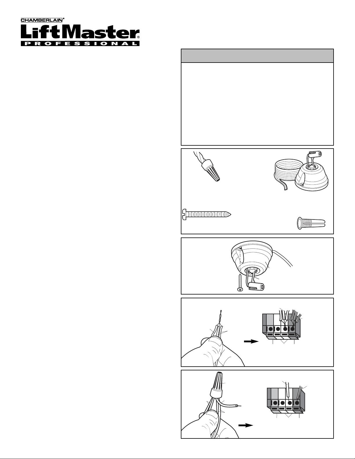
INSTALLATION
1. Open your garage door and park your vehicle outside of
the garage.
2. Determine the mounting location on or near the ceiling
and fasten the parking assist using the screw and anchor
provided (Figure 1).
3. Depress tabs under the wires and temporarily remove
the white and white/black safety sensor wires from the
garage door opener.
4. Stripping the wires prior to installation:
If installing one parking assist: Separate white and
white/black wires and strip 7/16" (11 mm) of insulation
from the parking assist wires.
If installing two parking assists: Cut 6" (15 cm) of
wires from the end of one of the parking assist wires for
use as connection wires. Separate white and white/black
wires and strip 7/16" (11 mm) of insulation from both ends
of the connection wire.
5. Connecting the wires to install:
If installing one parking assist: Twist like colored wires
for the parking assist and the safety sensors together.
Insert twisted wires into quick-connect holes: white to
white and white/black to grey (Figure 2).*
If installing two parking assists: Separate white and
white/black wires and strip 7/16" (11 mm) of insulation
from the end of the parking assist wires. Twist like
colored wires for the parking assist, safety sensors and
connection wire together. Secure with wire nut (provided).
Insert loose end of connection wires into quick-connect
holes: white to white and white/black to grey (Figure 3).*
* Please reference your garage door opener owner’s
manual for proper wire installation.
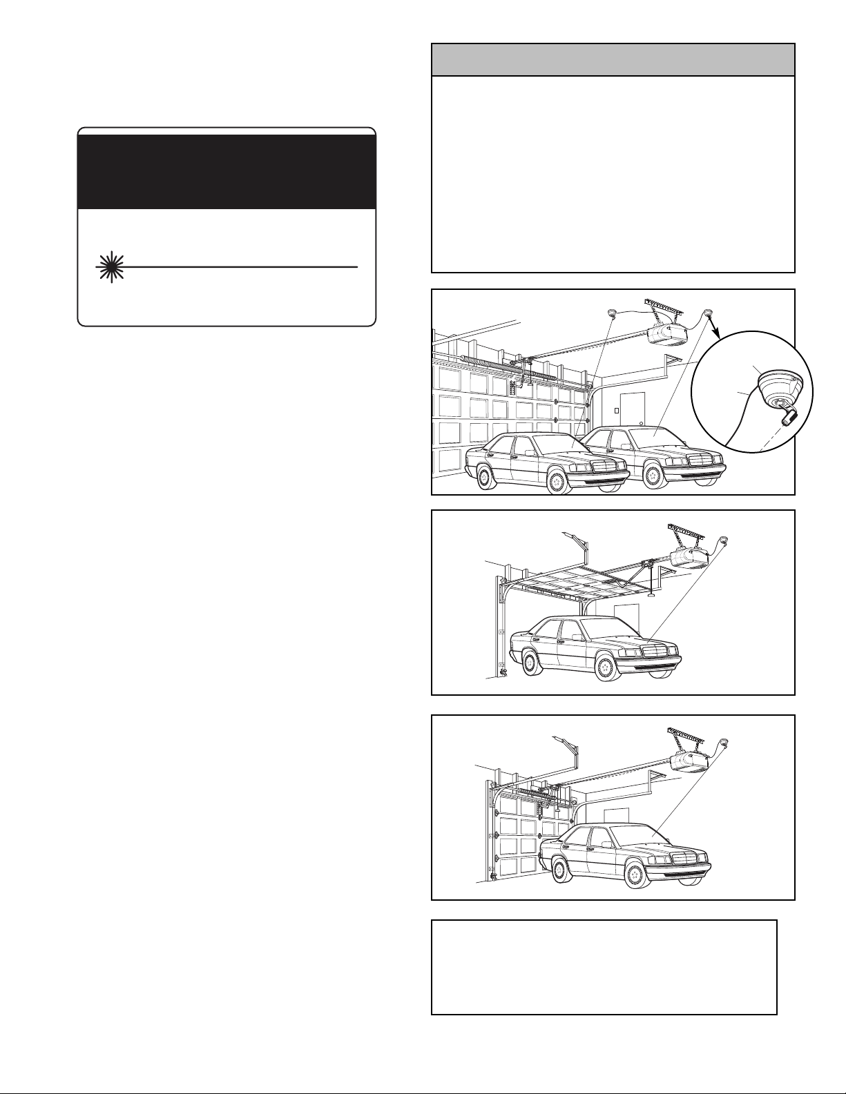
SET UP AND ADJUSTMENT
1. Drive your vehicle into the garage and park in the location
you want to park your vehicle each time (Figure 4).
2. Activate the parking assist locator by obstructing the path
of the safety reversing sensors. The laser will emit a
pulsing bright red beam. Using the swivel mount, aim the
red beam to a location on the dash or hood that can
easily be seen while seated in the driver’s seat.
NOTE: The laser will shut off automatically in 1 minute. If
you are not finished adjusting the beam and it turns off,
simply obstruct the path of the safety reversing sensors
again to re-activate the beam.
3. Sit in the driver’s seat and confirm that you can easily
see the location of the red beam. This location is now
your point of reference for parking your vehicle (Figure 5).
CAUTION: Do not stare directly into the beam. Repeat
steps for installation on optional 2nd laser accessory kit.
To avoid eye INJURY or damage to product:
• NEVER point the laser at anyone.
• NEVER look directly into the laser beam.
• NEVER disassemble the laser.
• The parking assist is NOT a substitute for safe parking
practices.
• Use of controls or adjustments, or the performance or
procedures other than specified can result in hazardous
radiation exposure.
• ONLY for use on Chamberlain manufactured garage door
openers.
WARNING
WARNING
WARNING
Figure 1
(2)
)
Figure 2
Figure 3
Carton Inventory
CAUTION
Wire Nuts (2)
Écrou pour Fils
Capuchones de Emplame (2)
Screw 6ABx1-1/4" (1)
Vis 6ABx1-1/4 po (1)
Tornillo 6ABx1-1/4 de pulg. (1)
(2)
Labels
Not Shown
Parking Assist (1)
Assistance de Garage (1)
Guía de Estacionamiento (1)
Anchor (1
White Parking
Assist Wires
Wire Nut
(provided)
White Connection
Wire to Terminal
White Safety
Sensor Wires
Repeat with white/black wires.
White Connection Wire
Red White Grey
Quick-Connect Terminals
Black/White
Connection Wire
Page 2
© 2006, The Chamberlain Group
114A3174B All Rights Reserved
NOTE: Periodic adjustment of the beam may be required
from time to time and is to be used only with the vehicle
used during the initial setup. Re-set the adjustment
according to SET UP and ADJUSTING steps 1-3 for that
vehicle.
OPERATION
1. Open the garage door by activating the automatic
garage door opener and drive your vehicle into parking
space.
2. The red beam can be seen moving across the hood of
your vehicle as you drive further into the garage
(Figure 5).
3. Stop the vehicle when the beam is positioned at the
location you confirmed in step 3 during the Set Up and
Adjustment (Figure 6).
NOTE: The laser is automatically actuated every time you
drive into your garage. The beam will automatically
deactivate after approximately 1 minute. A residual
reflection of the red beam from the windshield may appear
on the walls or objects in your garage. When operating a
vehicle, always ensure that there are no objects on the
floor of the garage or in the path of your vehicle. This
parking assist is not a substitute for safe parking practices.
TROUBLESHOOTING
If the laser does not emit a beam:
• Verify nothing is obstructing the safety sensor lens.
• Verify nothing is blocking the parking assist lens.
• Verify that connections are not reversed wired.
• Verify that all connections are secure as identified in the
installation.
• Confirm that the parking assist is aimed toward the
garage floor.
• Obstruct the path of the safety reversing sensors and
look for the red spot on the garage floor.
Please refer to your Liftmaster owner’s manual for
additional information on your garage door opener and the
safety sensors.
For Service Dial Our Toll Free Number:
US: 1-800-528-2817
Canada: 1-800-654-4736
www.liftmaster.com
To avoid eye INJURY or damage to product:
• NEVER point the laser at anyone.
• NEVER look directly into the laser beam.
• NEVER disassemble the laser.
• The parking assist is NOT a substitute for safe parking
practices.
• Use of controls or adjustments, or the performance or
procedures other than specified can result in hazardous
radiation exposure.
• ONLY for use on Chamberlain manufactured garage door
openers.
WARNING
WARNING
WARNING
Figure 6
Figure 5
Replacement Parts List
Wire Nuts 23B293
Parking Assist 975LM and 975LMC
Figure 4
Parking Assist
Wire
Parking Assist
CAUTION
ATTENTION
LASER RADIATION
DO NOT STARE INTO BEAM
RAYONNEMENT LASER
NE PAS REGARDER DIRECTEMENT
LE RAYONNEMENT LASER
Maximum power output: < 1mW @ 635 - 670nm
Puissance de sortie maximum: < 1mW @ 635 - 670nm
CLASS II LASER PRODUCT
APPAREIL AU LASER DE CLASSE II
132C2469-1
CAUTION
Page 3

Modèle 975LM et 975LMC
Liftmaster Laser Garage
Assistance de garage
Manuel d'utilisation
Assistance de Garage
Le Pivot
Blanc Détecteurs
de Sécurité Fil
Blanc Assistance
de Garage Fil
Trous de Branchement Rapide
Rouge Blanc Gris
Répéter avec blanc-noir fils.
Blanc Connexion Fils
Blanc-Noir
Connexion Fils
Pour éviter toute LÉSION des yeux ou les dommages du produit :
• Il NE faut jamais pointer le laser à qui que ce soit.
• Le rayon laser NE doit jamais être pointé aux yeux.
• Il NE faut jamais démonter le laser.
• L'assistant de garage N'EST pas un remplacement pour les bonnes
pratiques de garage.
• Utiliser les commandes, les réglages ou procédures autres que
celles spécifiées peut causer des risques d'exposition à des
radiations dangereuses.
• UNIQUEMENT pour utilisation avec les ouvre-porte de garage
fabriqués par Chamberlain.
AVERTISSEMENT AVERTISSEMENT
AVERTISSEMENT
AVERTISSEMENT
Figure 1
Figure 2
Figure 3
Inventaire de l'emballage
INSTALLATION
1. Ouvrir la porte du garage et garer le véhicule à l'extérieur du
garage.
2. Déterminer l'emplacement de montage sur le plafond, ou
àproximité, et monter l'assistant de garage avec les vis et les
chevilles fournies (Figure 1).
3. Appuyer sur les languettes sous les fils et enlever
temporairement les fils blanc et blanc-noir de détecteur de
sécurité de l'ouvre-porte de garage.
4. Dénudage des fils avant l'installation :
Installation d'un assistant de garage : Séparer les fils
blanc et blanc-noir et dénuder 11 mm (7/16 po) de l'isolant
des fils de l'assistant de garage.
Installation de deux assistants de garage : Couper 15 cm
(6 po) de l'extrémité d'un des fils d'assistant de garage pour
utilisation avec les fils de connexion. Séparer les fils blanc et
blanc-noir et dénuder 11 mm (7/16 po) de l'isolant des deux
extrémités de fil de connexion.
5. Branchement des fils :
Installation d'un assistant de garage : Torsader ensemble
les fils de la même couleur de l'assistant de garage et des
détecteurs de sécurité. Insérer les fils torsadés dans les trous
de branchement rapide, blanc dans blanc et blanc-noir dans
gris (Figure 2).*
Installation de deux assistants de garage : Séparer les fils
blanc et blanc-noir et dénuder 11 mm (7/16 po) d'isolant de
l'extrémité des fils d'assistant de garage. Torsader ensemble
les fils de la même couleur de l'assistant de garage, des
détecteurs de sécurité et des fils de connexion. Attacher avec
un écrou à fils (fournis). Insérer les fils torsadés dans les
trous de branchement rapide, blanc dans blanc et blanc-noir
dans gris (Figure 3).*
*Consulter l'installation des fils dans le manuel d'utilisation
de l'ouvre-porte de garage.
PARAMÈTRES ET RÉGLAGES
1. Conduire le véhicule dans le garage et le garer à l'endroit
normal désiré (Figure 4).
2. Activer le localisateur de l'assistant de garage en bloquant le
passage des détecteurs d'inversion de sécurité. Le laser
émet un rayon à impulsion rouge vif. En utilisant le pivot,
pointer le rayon rouge à l'endroit du tableau de bord ou du
capot qui peut être facilement vu du siège du chauffeur.
REMARQUE : Le laser s'éteint automatiquement après une
minute. Si le réglage n'est pas fini avant l'extinction du laser, il
suffit de bloquer le passage des détecteurs d'inversion de
sécurité pour réactiver le rayon.
3. Assis dans le siège du chauffeur, vérifier qu'il est possible de
voir l'emplacement du rayon rouge. Cet emplacement est le
nouveau point de référence pour garer le véhicule (Figure 5).
ATTENTION : Le rayon ne doit pas être pointé
directement dans les yeux. Répéter la procédure pour
l'installation optionnelle du second kit de laser accessoire.
ATTENTION
Écrou pour Fils
Vis 6ABx1-1/4 po (1)
(2)
Assistance de Garage (1)
Cheville (1)
Les Étíquettes (2) Non Illustré
Blanc Assistance
de Garage Fils
Blanc Connexion Fil
Écrou à Fil
(fournier)
Blanc Connexion
Fil á Borne
Blanc Détecteurs
de Sécurité Fil
Répéter avec blanc-noir fils.
Rouge Blanc Gris
Trous de Branchement Rapide
Blanc-Noir
Connexion Fils
Page 4

© 2006, The Chamberlain Group
114A3174B Tous droits réservés
REMARQUE : Il peut être nécessaire de faire un réglage
périodique du rayon et ce, uniquement avec le véhicule utilisé
pendant le réglage initial. Faire un nouveau réglage en suivant
les étapes 1 à 3 de PARAMÈTRES et RÉGLAGES pour ce
véhicule.
FONCTIONNEMENT
1. Ouvrir la porte du garage en activant l'ouvre-porte de garage
automatique et conduire le véhicule dans l'espace du garage.
2. Il est possible de voir le déplacement du rayon rouge sur le
capot du véhicule alors que le véhicule avance dans le
garage (Figure 5)
3. Arrêter le véhicule quand le rayon est en position à l'endroit
confirmé à l'étape 3 de Paramètres et réglages (Figure 6).
REMARQUE : Le laser est activé automatiquement chaque fois
que le véhicule est conduit dans le garage. Le rayon est
désactivé automatiquement après environ une minute.Il est
possible qu'une réflexion secondaire du rayon rouge, venant du
pare-brise, apparaisse sur les murs ou des objets dans le
garage. En conduisant le véhicule, toujours vérifier qu'il n'y a
aucun objet sur le sol du garage ou dans le passage du
véhicule. L'assistant de garage n'est pas un remplacement pour
les bonnes pratiques de garage.
DÉPANNAGE
Si le laser n'émet pas de rayon :
• Vérifier que rien ne bloque l'objectif du détecteur de sécurité.
• Vérifier que rien ne bloque l'objectif de l'assistant de garage.
• Vérifier que les fils ne sont pas inversés.
• Vérifier que tous les branchements sont bien faits,
conformément aux instructions.
• Vérifier que l'assistant du garage est pointé au sol du garage.
• Bloquer le passage des détecteurs d'inversion de sécurité et
observer le point rouge sur le sol du garage.
Consulter le manuel d'utilisation du Liftmaster pour obtenir des
renseignements complémentaires sur l'ouvre-porte de garage et
les détecteurs de sécurité.
Pour service, priére de composer numéro sans Frais :
1-800-654-4736
www.liftmaster.com
Pour éviter toute LÉSION des yeux ou les dommages du produit
• Il NE faut jamais pointer le laser à qui que ce soit.
• Le rayon laser NE doit jamais être pointé aux yeux.
• Il NE faut jamais démonter le laser.
• L'assistant de garage N'EST pas un remplacement pour les bonnes
pratiques de garage.
• Utiliser les commandes, les réglages ou procédures autres que
celles spécifiées peut causer des risques d'exposition à des
radiations dangereuses.
• UNIQUEMENT pour utilisation avec les ouvre-porte de garage
fabriqués par Chamberlain.
AVERTISSEMENT AVERTISSEMENT
AVERTISSEMENT
AVERTISSEMENT
Figure 6
Figure 5
Liste des pièces de rechange
Écrous pour fils 23B293
Assistance de garage 975LM et 975LMC
Figure 4
Assistance
de Garage
Assistance de
Garage Fil
CAUTION
ATTENTION
LASER RADIATION
DO NOT STARE INTO BEAM
RAYONNEMENT LASER
NE PAS REGARDER DIRECTEMENT
LE RAYONNEMENT LASER
Maximum power output: < 1mW @ 635 - 670nm
Puissance de sortie maximum: < 1mW @ 635 - 670nm
CLASS II LASER PRODUCT
APPAREIL AU LASER DE CLASSE II
132C2469-1
ATTENTION
 Loading...