

LifeWatch VSPS User Manual

Dear LifeWatch Technologies Ltd. device owner:
Thank you for selecting the LifeWatch Technologies Ltd. Vital Signs Patch
(VSP) device, CG-1101XX (models CG-1101U, CG-1101B, CG-1101UC).
Please read this user guide before you start using your new device.
The guide contains important information about your device as well as
clear instructions about how to use it.
If you have any questions about the new Vital Signs Patch, please
contact:
Customer Service at:
1
Copyright Declaration
LifeWatch Technologies Ltd.® All rights reserved.
LifeWatch Technologies Ltd., LifeWatch Technologies Ltd. logo,
Vital Signs Patch System
are trademarks or registered trademarks
All other brand names and product names used in this document are trade
names, service marks, trademarks, or registered trademarks of their
The information and screens provided in this manual are subject to
feWatch Technologies Ltd. SHALL NOT BE LIABLE FOR TECHNICAL
OR EDITORIAL ERRORS OR OMISSIONS CONTAINED HEREIN; NOR
FOR INCIDENTAL OR CONSEQUENTIAL DAMAGES RESULTING
FROM THE FURNISHING, PERFORMANCE, OR USE OF THIS
LifeWatch Technologies Ltd.
7670202
Tel: 972 8 9484000
Fax: 972 8 9484044
Email: users@lifewatch.com
please read
Copyright © 2013
LifeWatch Inc., LifeWatch Inc. logo,
and VSP
of LifeWatch Technologies Ltd.®.
respective owners.
change without notice.
Li
MATERIAL.
Authorized representatives:
Europe
Obelis s.a
Boulevard Général
Wahis 53
1030 Brussels,
BELGIUM
Tel: + (32) 2. 732.59.54
Fax: + (32) 2.732.60.03
E-mail: mail@obelis.net
Before using the VSP System
and Precautions in Appendix A and the
Contraindications on pages 5 and 6.
USA
LifeWatch, Inc.
O’Hare International Center
10255 West Higgins Road
Suite 120
Rosemont, IL 60018
Tel: 847-720-2295
Fax: 847-720-1995
Toll Free: 800-633-3361
Fax: 800-954-2375
Email:
webmaster@lifewatch.com
2
Israel
2 Pekeris St.
Rehovot
Israel
the Warnings
Declaration of Conformity
disposable patch, a reusable
processing unit and a Smartphone based application.
internally powered equipment with
equipment
dust and splashing water.
Class IIa
Body Temperature)
:2005
however this does not preclude the possibility
of electronic interference from other equipment where the device will
need to be activated at a distance from the source(s) of
(QS)
9001:2008, ISO 13485:2003
Requirements
Equipment not suitable for use in the presence of
anesthetic mixture with air or with Oxygen or Nitrous Oxide.
Federal Law (USA) restricts this device to sale by
or on the order of a practitioner licensed by the
law of the State in which he/she practices to use
The VSP System consists of a
The VSP System is classified as
type BF applied parts.
The device is suitable for continuous operation.
The Patch (CG-1101XX) is classified as type IP54
affords protection against
The VSP System is classified by the MDD as a
(Pulse oximeter; ECG; Heart Rate;
The VSP System is compliant with IEC 60601-1
IEC 60601-1-2:2007;
and
which
device
interference.
LifeWatch Technologies’ Quality System
certified to ISO-
CE 93/42 MDD and Canadian QS
is
WARNING
No modification of this equipment is allowed
Refer servicing to qualified personnel only.
DANGER
or order the use of the device.
3
flammable
Graphic Symbols on VSP System
indicates important general information for
Refer to instruction manual/ booklet
NOTE: On ME EQUIPMENT "Follow instructions
anufacture
for storage of the
WEEE Directive for disposal of Electrical and
heart rate,
vital signs or accelerometer
nor take any actions of a medical nature based on your
understanding UNLESS you are a medical professional.
Label Description
Warning
Precaution
Notes;
using the system successfully.
for use.”
Manufacturer and date of m
XXXX
Type BF Applied Part
Indicates the temperature limits
device.
Electronic Equipment
Symbol for no SPO2 alarms
Warning
Under no circumstances should you interpret your
temperature, saturation or respiration
data
body
4
Intended Use
The Vital Signs Patch system is intended to be used by patients for
the continuous, non-invasive monitoring of ECG, Heart Rate (HR),
respiration, body temperature and blood saturation, when
prescribed by a physician or other qualified healthcare professional.
The VSP includes pacemaker detection to show pulses of
pacemaker on the screen and can therefore be used by users with a
pacemaker.
Readings obtained using the
monitoring
using the
should not
standard
12-lead vital signs via standard
be compared with readings obtained
non-standard
3-lead vital sign
electrode placement.
Contraindications
The Vital Signs Patch (VSP) is not intended for use by
persons with any type of defibrillator, external or internal
(ICD); the VSP must be detached from the patient before
using a defibrillator on the patient.
The VSP is not intended for the treatment or alleviation of
disease
The VSP is not to be used in a magnetic resonance imaging
(MRI) environment; the VSP unit must be removed from the
patient’s skin before he/she undergoes MRI analysis.
The VSP is not a “life-saving” or therapeutic device; the VSP
supplies vital signs data to a doctor or technician for the
purpose of diagnosis by such (or other qualified) personnel
The VSP is not intended for use for patients who have
undergone surgery on the chest and who still have a fresh
incision on the chest
The VSP is not intended for use on patients with any skin
damage on the area where the VSP is placed (such as burns,
irritation, infections, wounds, etc.)
5

Contraindications regarding ECG/Heart Rate
Due to the possible seriousness of the abnormal heart rhythms that
can be associated with the following conditions, persons with these
conditions should consult with their physician before using the VSP:
Coronary heart disease
Valvular heart disease
Heart transplant
Heart failure
6

General conditions for use of the VSP
Before using the VSP, check that you comply with the following
conditions:
You understand the principles of operation described in this
manual.
You speak and understand English or have access to a fluent
English speaker who can explain how to use the device.
You can attach the VSP to your body or have access to
someone who can attach the VSP to your body.
You can operate the Gateway application software or have
access to someone who can operate the Gateway application
software.
You can operate simple push-buttons.
Precautions:
Use the device only for the purposes described in these
instructions for use.
User Manual Warning: To prevent fire, do not expose the unit
unnecessarily to moisture, nor to or excessive heat.
Refer servicing to qualified personnel only
Do not use this device if it is not working properly, or if it has
suffered any damage.
7

Table of Contents
1 Glossary ................................................................................ 10
2 VSP System Introduction ................................................... 11
2.1 G
2.2 T
ENERAL DESCRIPTION
HE
VSP KIT ................................................................ 12
................................................. 11
3 Physical Features ................................................................ 13
3.1 P
3.2 P
ARTS
......................................................................... 13
ATCH
......................................................................... 13
3.3 BRAIN ........................................................................ 14
3.4 G
3.5 G
ATEWAY APPLICATION
ATEWAY RECHARGING PROCEDURE
................................................. 15
............................. 17
4 Using the VSP System ........................................................ 18
4.1 G
4.2 P
ENERAL
ATCH
..................................................................... 18
......................................................................... 18
4.2.1 Preparing the Skin .............................................. 18
4.2.2 Placing the Upper 3-lead Patch .......................... 19
4.2.3 Placing the Lower 3-lead Patch .......................... 20
4.3 I
4.4 R
NSTALLING THE BRAIN
EMOVING THE
VSP ..................................................... 22
.................................................. 21
5 Using the Gateway Application ......................................... 23
5.1 S
5.2 VSP S
5.3 G
TARTING THE APPLICATION
CREEN
ATEWAY APPLICATION FUNCTIONS
............................................................... 23
.......................................... 23
............................... 23
5.3.1 Displaying the Main Screen ................................ 24
5.3.2 Displaying Sensor Data ...................................... 24
5.3.3 Displaying HW/SW Version on the About Screen25
8

5.3.4 Displaying Alerts ................................................. 25
5.3.5 Creating Manual Events ..................................... 26
6 Heart Rate Calculation Method .......................................... 28
6.1 I
6.2 M
NTRODUCTION
ETHOD OF CALCULATION
.............................................................. 28
............................................. 28
7 Maintenance ......................................................................... 29
7.1 C
7.2 C
7.3 C
7.4 E
ONDITIONS OF USE
ARING FOR YOUR
LEANING
NVIRONMENT
.................................................................... 30
.............................................................. 30
..................................................... 29
VSP ................................................ 29
8 Troubleshooting .................................................................. 31
9 Specifications ....................................................................... 32
9.1 VSP B
9.2 VSP P
RAIN SPECIFICATIONS
ATCH SPECIFICATIONS
......................................... 32
......................................... 35
9.3 TRANSMISSION SPECIFICATIONS ..................................... 36
Appendix A Warnings and Precautions ................................... 37
END USER LICENSE AGREEMENT - SOFTWARE LICENSE
AGREEMENT ............................................................................... 47
NOTICE POLICY AND MEDICAL WASTE DISCLAIMER ........ 50
9

1 GLOSSARY
BRAIN
ECG
Gateway device
VSP System User Guide
Main Processing Unit, vital sign data
communication device that collects the body vital
signs and sends these signs to the gateway
device. The BRAIN can receive settings updates
from the Gateway
Electrocardiogram; a representation of the
heart's electrical activity recorded from
electrodes on the body surface
Device for receiving vital signs from the BRAIN
and transmitting them on to the monitoring
center; the gateway can receive settings updates
from the monitoring center
Heart Rate
Monitoring
Center
Respiration Rate
RF
Saturation
Temperature
VSP
CG-1101XX
The number of heartbeats per unit of time,
usually per minute.
Monitoring Center equipped with hardware and
software that receives, analyzes and stores vital
signs signals received from the VSP system, and
can generate reports for the medical staff
The number of movements of the chest wall per
unit of time, indicative of inhalation and
exhalation
A range of radio frequencies used for wireless
transmission
Blood’s oxygen saturation level measured in
percentage
The patient’s body temperature recorded from a
thermistor on the body surface
Vital Signs Patch system
Internal Part Number indicating the type of Vital
Signs Patch (CG-1101C, CG-1101B
or CG-1101UC)
10
VSP System User Guide
2 VSP SYSTEM INTRODUCTION
2.1 General Description
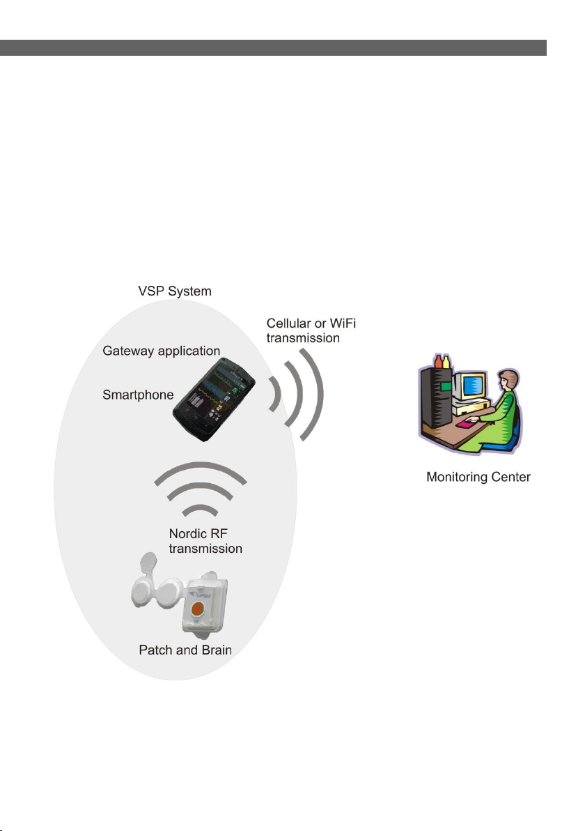
The VSP system is a medical device that allows recording of heart
rate, ECG (up to 3 Lead), body temperature, oxygen blood
saturation and respiration; the VSP also enables transmission of
vital sign recordings to a Monitoring Center, thereby allowing your
physician or other medical personnel to monitor your health
condition anywhere, any time.
Figure 1 - Vital Sign Patch System
11

2.2 The VSP Kit
VSP System User Guide
1. 3-lead Disposable Patch for
upper placement
2. 3-lead Disposable Patch for
lower placement
3. Brain
4. Gateway device
5. Gateway Charger
6. Quick User Guide (not shown)
Figure 2 - VSP Kit Components
12
VSP System User Guide
3 PHYSICAL FEATURES
3.1 Parts
The VSP system includes the following components:
Disposable Patch (CG-1101XX)
Brain
Gateway application
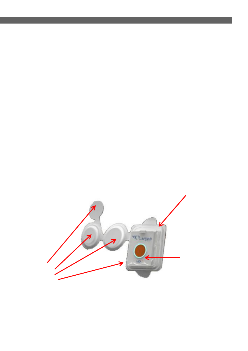
3.2 Patch
The Patch is a disposable unit that is attached to the body and contains
the following sensors:
ECG sensor
Temperature sensor
Blood oxygen saturation sensor
Respiration sensor
Sensors
Figure 3 - Patch Components (general)
13
Cradle
BRAIN

VSP System User Guide
3.3 BRAIN
The BRAIN is a non-disposable part, containing an RF transmitter and
a receiver for communicating with the Gateway. The BRAIN connects
to the Patch via a dedicated cradle located on the Patch.
The BRAIN includes a processor unit, and receives power and vital
signs data from the Patch. In addition, the Brain has an accelerometer
for sensing when a patient falls.
The BRAIN has a centrally placed event button for recording and
subsequent transmission of manual events. Events can also be
triggered manually via an icon on the Gateway application.
A LED rim around the button blinks to indicate the status of the VSP
system - a green light indicates that the VSP system is working
properly, while a red light indicates a problem (refer to the
troubleshooting section for details of possible problems).
Figure 4 - Brain Components
14
VSP System User Guide
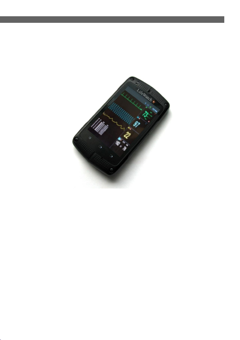
3.4 Gateway Application
The Gateway application runs on a smartphone using the Android
operating system, RF capabilities (Nordic), and a proprietary
application.
Figure 5 - Gateway Application
15
 Loading...