


/7.%23-!.5!,
7)4(!33%-",9).3425#4)/.3
Copy

2
INSTRUCTION #1034145
The product you just purchased could be FREE!
Register your product at www.lifetime.com and receive three important
benets:
1. You automatically will be entered to win $200 in our monthly drawing!
2. In the unlikely event of a product recall or safety modication, we can
notify you immediately and directly.
3. You may choose to receive Preferred Customer Announcements and
promotions regarding new Lifetime products.
www.lifetime.com
**U.S. and Canada customers ONLY**
IF ASSISTANCE IS NEEDED,
DO NOT CONTACT THE STORE!!!
CALL OUR CUSTOMER SERVICE DEPARTMENT at 1 (800) 225-3865
HOURS: 7:00 a.m. to 5:00 p.m. Monday through Friday (Mountain Standard Time)
**Call, or visit our Web site for Saturday hours**
Save this instruction in the event that the manufacturer has to be contacted for
replacement parts.
MODEL #51546
WARNING
To ensure your safety, do not attempt to assemble
this system without reading and following all
instructions carefully. Identify and inventory the
parts using the Parts List. Failure to comply with
any of the warnings in these instructions may
result in serious personal injuries such as cuts,
broken bones, nerve damage, paralysis, brain
injury, or death. Failure to comply may also result
in property damage. Please heed all warnings
and cautions.
FRONT COURT
TM
FAST TRACK
TM
BASKETBALL SYSTEM
1/11/2008
**For customers outside the U.S. or Canada, please contact the store for assistance.**
Copy
3
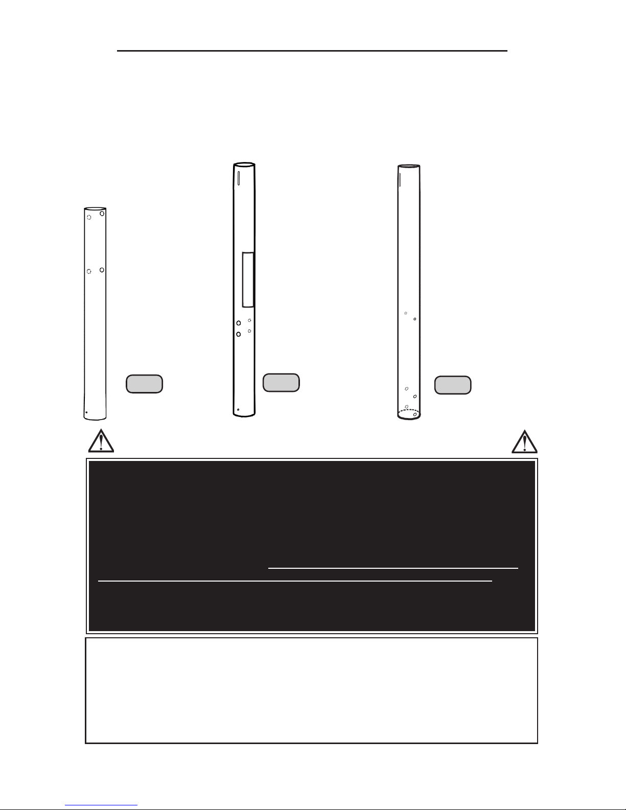
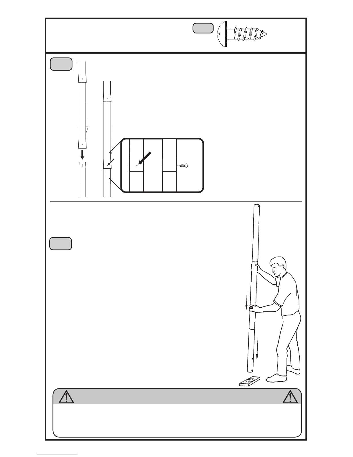
POLE SECTION IDENTIFICATION
TP
MP
BP
Identify the pole sections before beginning assembly. Failure to
assemble the pole sections correctly may result in severe personal
injury or property damage as described on Page Two.
ONCE THE POLE SECTIONS HAVE BEEN SEATED, THEY
CANNOT BE SEPARATED.
Top Pole:
Four holes at
the top of the
pole and one
small hole at the
bottom. Shortest
pole.
Middle Pole:
One slot at the top
of the pole, four
holes in the middle
and one small hole
at the bottom.
Bottom Pole:
One slot at the
top of the pole,
two holes near
the middle and
two holes at the
bottom.
SAFETY INSTRUCTIONS
Most injuries are caused by misuse and/or not following instructions. Use
caution when using this system.
Owner must ensure that all players know and follow these rules for safe operation of
the system.
To ensure safety, do not attempt to assemble this system without following the
instructions carefully. Check entire box and inside all packing material for parts and/
or additional instruction material. Before beginning assembly, read the instructions
and identify parts using the hardware identier and parts list in this document.
Proper and complete assembly, use and supervision are essential for proper
orientation and to reduce the risk of accident or injury. A high probability of serious
injury exists if this system is not installed, maintained, and operated properly.
FAILURE TO FOLLOW THESE WARNINGS MAY RESULT IN SERIOUS INJURY OR
PROPERTY DAMAGE AND WILL VOID WARRANTY.
• If using a ladder during assembly, use extreme caution.
• Two capable adults are recommended for this operation.
• Check base daily for leakage. Leaks will cause system to fall.
• Assemble the pole sections properly. Failure to do so could cause the pole
sections to separate during play or transport.
• Minimum operational height is 7’6” (2.23m) to the rim.
4
PARTS LIST
ID Part # Description Qty.
TP 1018846 Top Pole 1
MP 1018845 Middle Pole 1
BP 1018847 Bottom Pole 1
LB 1018717 Left Backboard Bracket 1
RB 1018718 Right Backboard Bracket 1
BA 1023749 Backboard 1
AB 510022 Wheel 2
AC B110001 1/2” x 15 3/4” Axle 1
AD 504068 Counterbalance Spring 1
AE 1018843 Long Extension Arm 2
AF 1018844 Short Extension Arm 2
AG 1030034 Base 1
AH ZA76007 Rim 1
AI DA01500D Pole Pad 1
AJ 1018850 Pole Brace 2
AK BD00200 1/2” x 7” Axle 1
AL AM01500 Rim Support Channel 1
AM CF00199 1 1/4” Base Plug 2
AN AR00100 Fast TrackTM Inner Channel 1
AO 1023787 Fast TrackTM Outer Tube 1
AT 1018716 Pole Bracket 1
AU FS16400 Warning Sticker (One Applied) 2
AY FS05200 Height Sticker 1
AZ AG00602 Backboard Weight 2
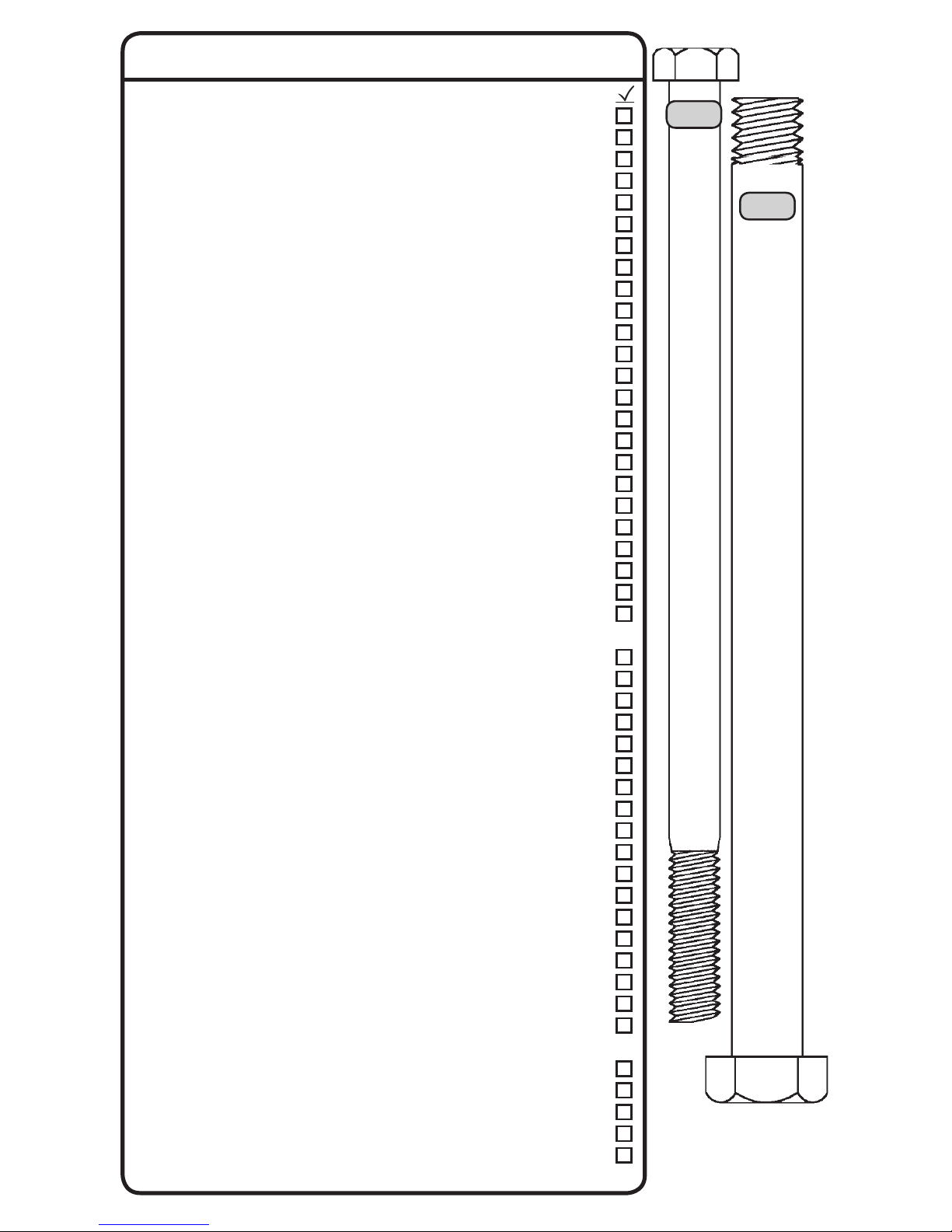
Main Hardware (1024989)
MA 302007 3/8” x 6 1/2” Hex Bolt 1
MB BN00300 1/4” Cap Nut 1
MC 300083 1/4” x 1 1/4” Hex Bolt 1
MD BA01500 1/2” x 1.4” Poly Spacer 2
ME 300087 5/16” x 1.5” Tap Bolt 1
MF 300095 5/16” Cap Nut 1
MG 301008 1/2” Centerlock Nut 5
MH BB01000 1/2” x 6 5/8” Hex Bolt 5
MJ 500038 1/2” x 3/8” Clear Poly Spacer 4
MK 500013 1/2” x .592” Black Poly Spacer 4
ML 302008 3/8” Centerlock Nut 3
MM 302064 3/8” x 3.5” Hex Bolt 2
MN 300031 3/8” Flat Washer 2
MP 300110 1/4” x 2 3/4” Hex Bolt 2
MQ 300022 1/4” Centerlock Nut 2
MR BS00800 5/16” x 1” Screw 8
MS BA01800 1/2” x 2.94” Spacer 2
MT 800324 3/8” x 2 5/16” Spacer 2
Base Hardware (1003546)
BD 1003221 1/4” Hex T-Nut 1
BB 300030 5/16” x 1” Hex Bolt 2
BC 300097 5/16” Nylock Nut 2
RC 302014 5/16” Flat Washer 5
BE 1003225 1/4” x 3.15” Hex Shoulder Screw 1
MA
MH

5
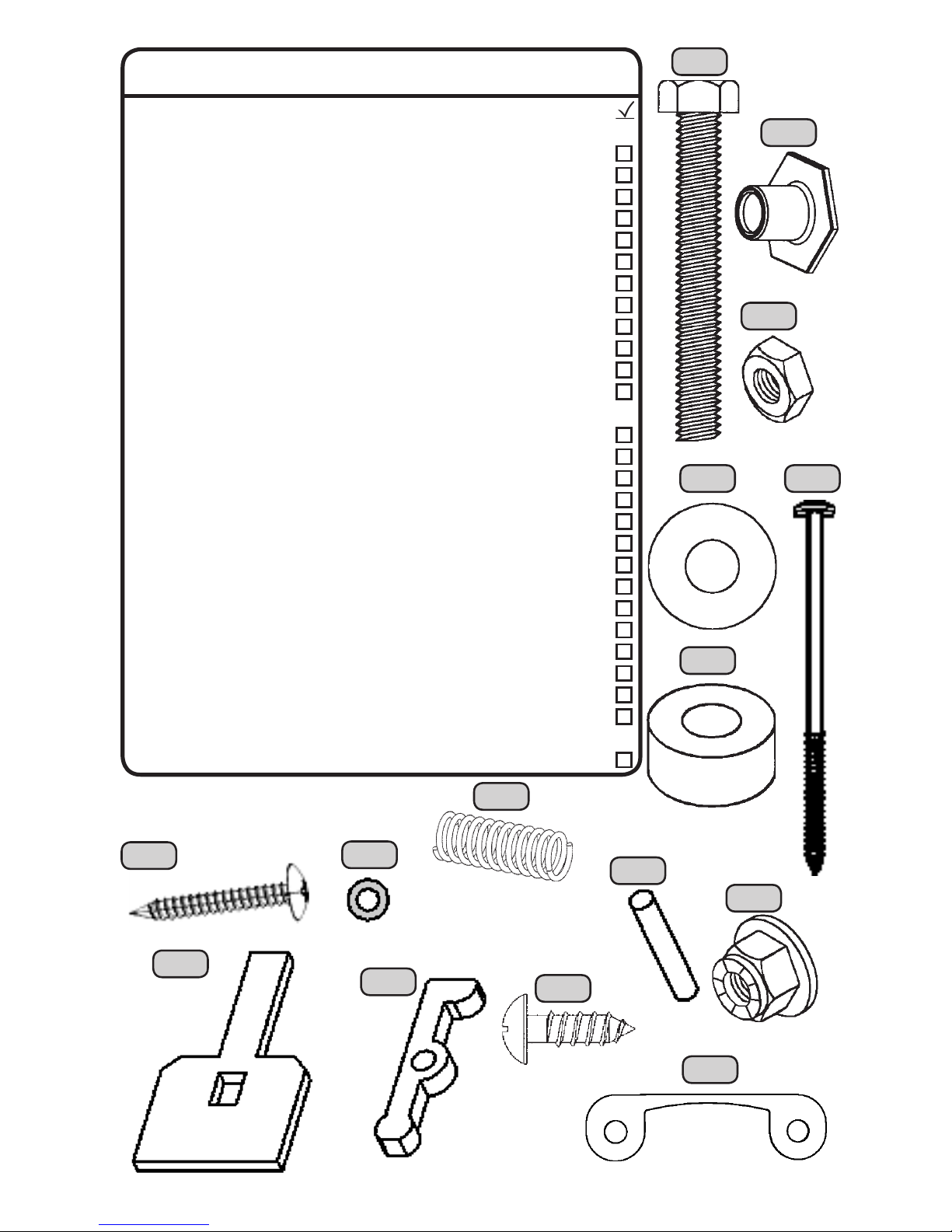
MQ
HARDWARE IS ACTUAL SIZE
(Unless otherwise indicated)
MP
MG
ML
MK
MJ
MR
AM
(Not actual size)
MB
MC
MD
ME
MF
MM
MN
BB
BC
BE
BD
MS
MT
1. Adjustable Wrench
2. 362 lb. of Sand/
Water Supply
3. 1/2” Wrenches (2)
4. 9/16” Wrenches (2)
5. 7/16” Wrenches (2)
6. 3/4” Wrenches (2)
Tools and Materials Required for Assembly
(Not Included)
7. 3/8” Socket Wrench
8. Funnel
9. Phillips Screwdriver
10. Scrap Wood or Cardboard
11. Rubber Mallet
12. Pliers
PARTS LIST
ID Part # Description Qty.
Fast TrackTM Hardware (1028796)
SA* 1023792 #8 x 1 1/4” Truss Screw 2
SB* 1023793 O-ring 2
SC 1023785 Lower Fast TrackTM Handle 1
SD 1024352 #6 x 2 1/2” Screw 8
SE 1023784 Handle End Cap 2
SF 1024787 Textured Handle Tube 1
SG* BG00300 Trigger Spring 1
SH* 1023881 Fast Track Lock Tab 1
SJ* 1023800 Push Button Lever 1
SK* 1023799 Push Button Shaft 1
SL* 1023788 Red Push Button 1
SM* 1023786 Upper Fast TrackTM Handle 1
Rim Hardware (HP19700)
RA 300066 5/16” Hex T-Nut 2
RK 300128 5/16” Jam Nut 2
RC 302014 5/16” Flat Washer 2
RD 302056 7/16” Rubber Washer 2
RE 302065 5/16” x 2 1/4” Tap Bolt 2
RF 302075D 3.5” U-Bolt 1
RG 302090 5/16” Nylock Flange Nut 4
RH 502060 Compression Spring 2
NC DD01000 Net Attachment Cord 1
RI DD00800 Net 1
RL CH11299 Black Spring Cover 1
RM CH11186 Silver Spring Cover 1
RJ ZA27310 Spring Retainer Plate 1
MN 300031 3/8” Flat Washer 2
Pole Joint Hardware (HH03200)
JA BS02000 1/4” x 3/4” Pole Joint Screw 2
SH
SG
SJ
SK
(Not actual size)
SD
SB
SA
RC
RG
RA
RK
RD
RE
RJ
(Not actual size)
JA
* Part of the Pre-assembled
Upper Handle w/ Button
7
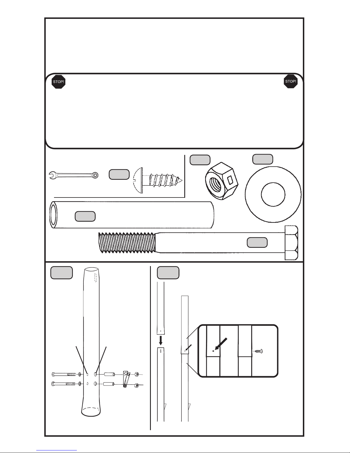
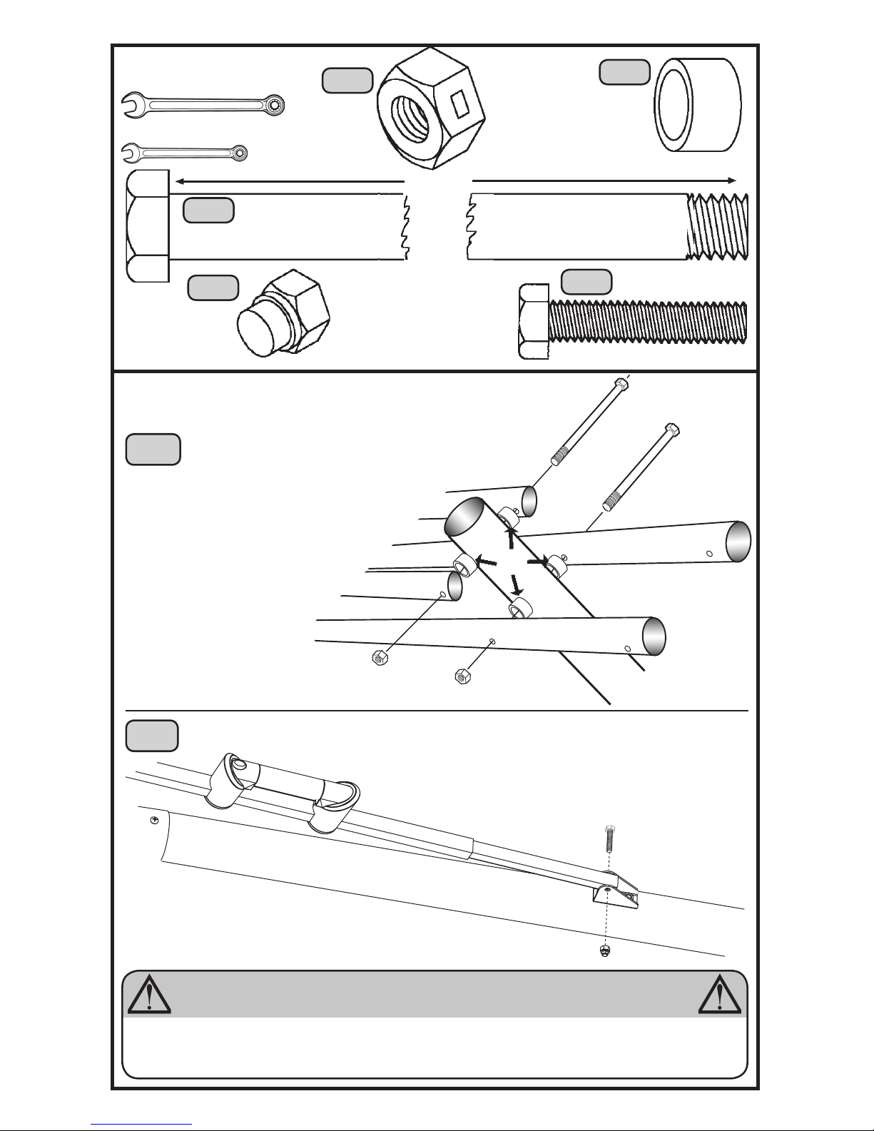
Before Beginning Assembly
A. Keep the hardware bags and their contents separate. If any parts
are missing, call our Customer Service Department.
B. Test t all Bolts by inserting them into their respective holes. If
necessary, carefully scrape away any excess powder coating buildup
from inside the holes. Do not scrape away all of the powder coating.
Bare metal may rust. You may need to pound some Bolts into place
with a hammer or mallet.
MM
MN MS ML
Large holes
Small
holes
AT
MP
Required For This Page:
9/16” Wrenches
Screwdriver
1 2
ML
MM
MS
(2)
(2)
(2)
MN
(2)
1024989
Completely tighten the Nuts.
TP
MP
JA
Align the hole in the Top Pole (TP)
with the slot in the Middle Pole (MP)
and slide the Top Pole over the
Middle Pole.
The Screw will spin freely once installed.
Insert a 1/4” x 3/4” Screw (JA)
through the small hole in the Top
Pole and into the Middle Pole.
Do not jam the poles
together until instructed.
JA
(1)
HH03200
8
BP
MP
TP
Strike each end of the pole rmly 5 to 6 times on a
piece of scrap wood or cardboard.
WARNING
The poles must be seated together!! Even if the poles cover the slots before seating,
you must strike them on the wood ve to six times!! Failure to seat the poles correctly
could allow the poles to separate during use, which could lead to serious personal
injuries or property damage as listed on Page Two.
Required For This Page:
Screwdriver
3
BP
MP
JA
The Screw will spin freely
once installed.
Insert the remaining 1/4” x 3/4” Screw (JA) through the
small hole in the Middle Pole and into the Bottom Pole.
Align the hole in the Middle Pole (MP) with the slot in
the Bottom Pole (BP) and slide the Middle Pole over the
Bottom Pole.
JA
(1)
HH03200
Do not jam the poles together until instructed.
4
This step cannot be reversed.
Do not hit your feet with the pole sections, as serious
injury could occur.
If the Top and Middle Poles do not completely cover
the slots on the Middle and Bottom Poles after
seating, DO NOT COMPLETE ASSEMBLY. Call our
Customer Service Department.
Scrap wood/cardboard

9
5
Required For This Page:
The attened end of the Pole Brace (AJ) attaches to
the Base (AG). The angled end attaches to the Pole.
AJ
RC
BB
RC
BC
Only nger
tighten the Nuts.
Repeat for the other side of the Base.
AG
1003546
BB
BC
(2)
RC
(4)
(2)
6
AB
AB
AC
BP
BP
AK
7

10
Required For This Page:
1003546
7/16” Wrenches
BE
(1)
BD
(1)
8
Rotate the Pole up so the 1/2” x 7” Axle (AK)
ts into the slots in the top of the Base.
Lay the pole on the ground with the
Bracket on the Middle Pole facing up.
Place the Base over the 1/2” x 15 3/4” Axle
(AC) and step on the Base so the Axle ts
into the slots in the bottom of the Base.
9
Completely tighten all Base and Pole Brace hardware now.
BD
BE
AJ
Tip the system forward so the
pole rests on the ground.
10
RB
LB
RF
Pliers
AK
AC
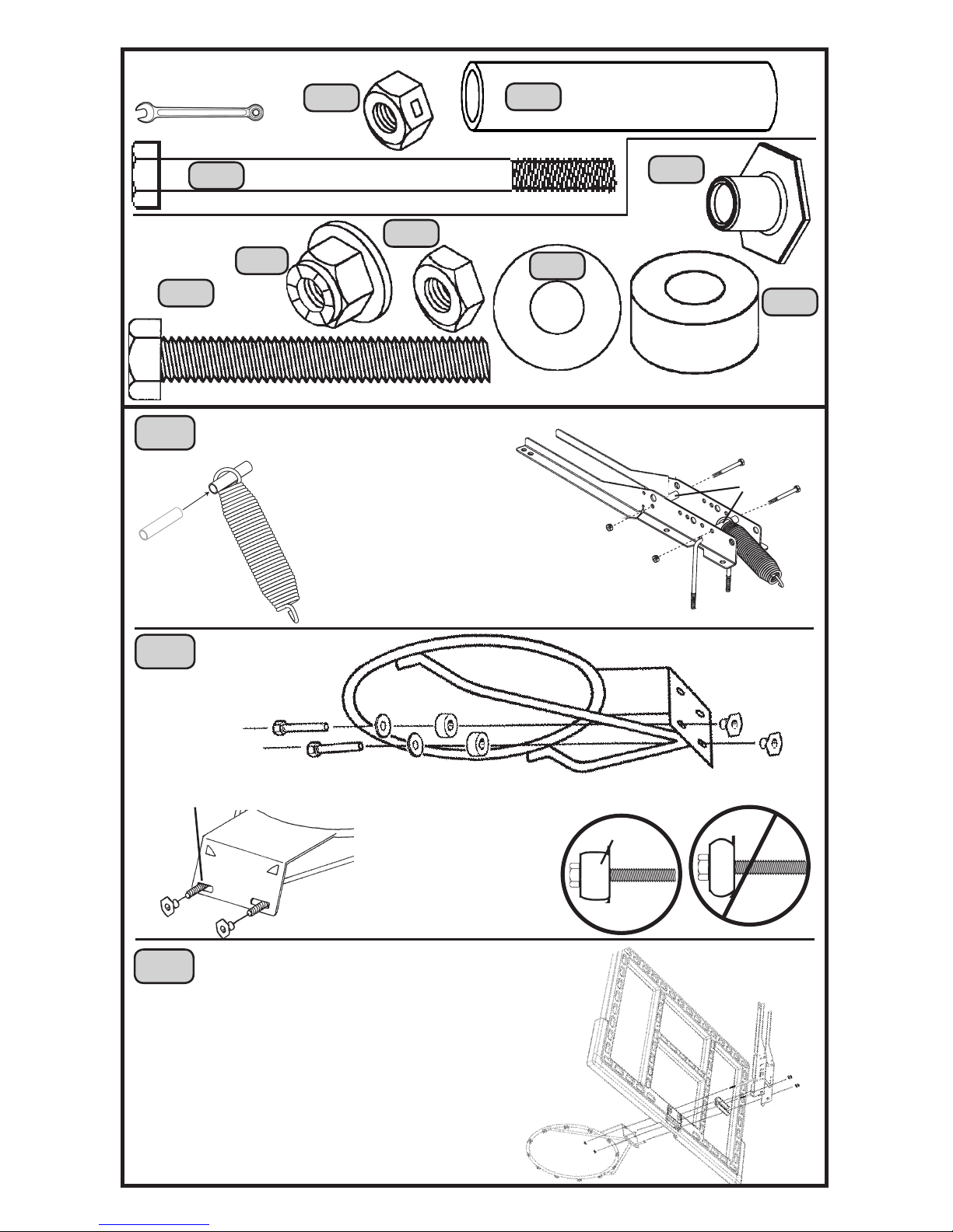
11
Required For This Page:
Slide Spacer (MT) into top of
Spring (AD).
11
7/16” Wrenches
MP
MT
(2)
1024989
(2)
MQ
(2)
12
RA
RE
RC RD
The Tap Bolts (RE) should be
at the outer edge of the holes.
Tighten the T-Nuts
(RA) only until the
Rubber Washers
(RD) begin to
bulge.
RD
AH
RA
RD
(2)
(2)
RE
RC
(2)
(2)
HP19700
13
Lay the Backboard (BA) on a
bench or table.
Tighten the Jam Nuts (RK)
onto the U-Bolt as far as
they will go.
Only hand tighten the
Nuts (RG).
RG
RK
AL
BA
(2)
(2)
RG
RK
MP
MP
MT
MQ
MQ
RB
RF
AD
LB
MT
AD

12
Required For
This Page:
1/2” Wrenches
HP19700
(2)
RG
(2)
3/8” Socket
Wrench
14
15
Bend the Backboard
Brackets (LB & RB) out.
MR
(8)
1024989
Tightening these Nuts later
will adjust the Rim tension.
Only hand tighten the
Nylock Flange Nuts (RG).
RM
RH
RL
MN
RG
RM
AH
The Silver Spring Cover
ts into the Rim slots.
This step is easier if the Rim is
facing up.
Do not overtighten the Screws. Only tighten them
a half turn after the head of the Screw contacts
the Backboard Brackets and Weights (AZ).
Use a 3/8” socket wrench
to insert the Screws (MR)
through the Backboard
Brackets and Backboard
Weights (AZ).
AZ
MR
MR
MR
MR
MR
MR
MR
MR
AZ
LB
RB
MN
RJ
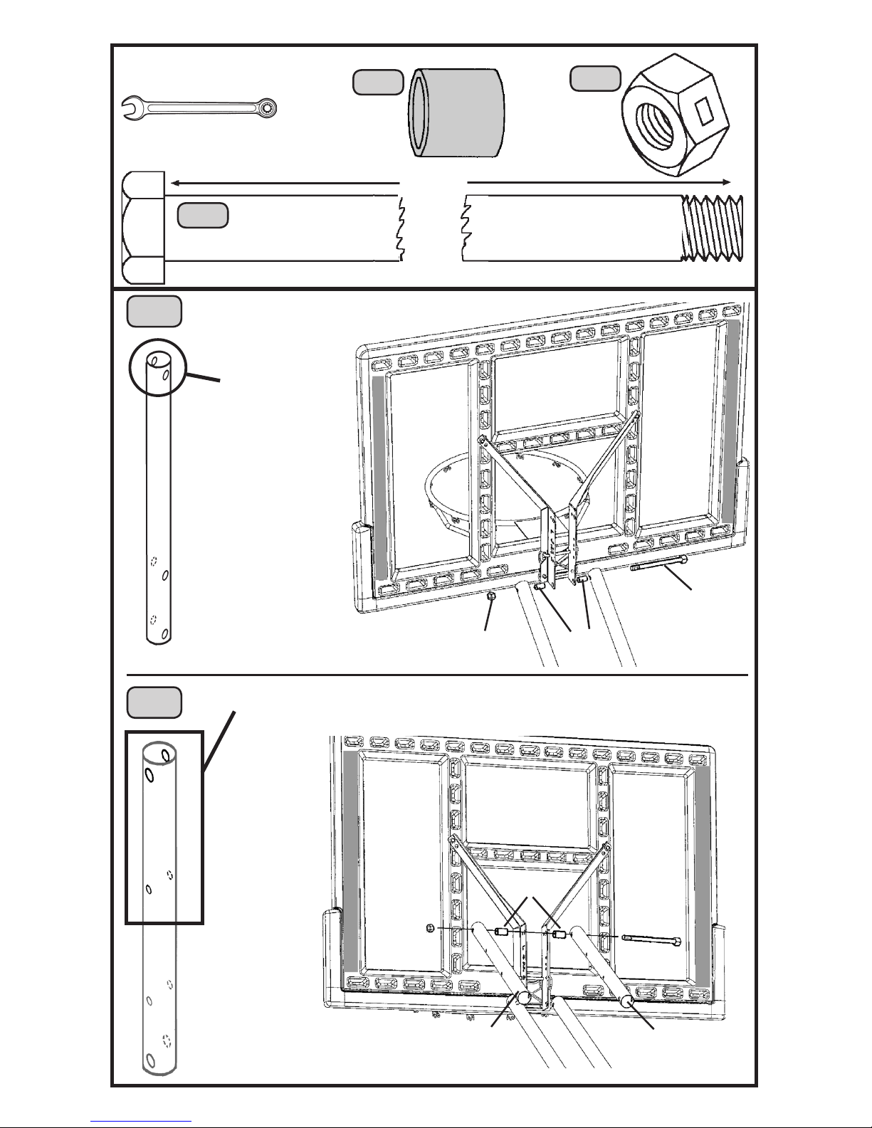
13
Required For This Page:
1024989
3/4” Wrenches
MH
(2)
MG
MK
(2)
(4)
6 5/8”
(Not actual length)
AF
MG
MK
MH
AF
Tighten the Nut
until it is ush
with the Bolt.
Attach the end with the two sets of holes further apart to the
Backboard Brackets.
17
AF
16
AE
MH
MK
MG
Attach this end of
the Long Extension
Arms (AE) to
the Backboard
Brackets
AE
AE
Tighten the Nut
until it is ush with
the Bolt.
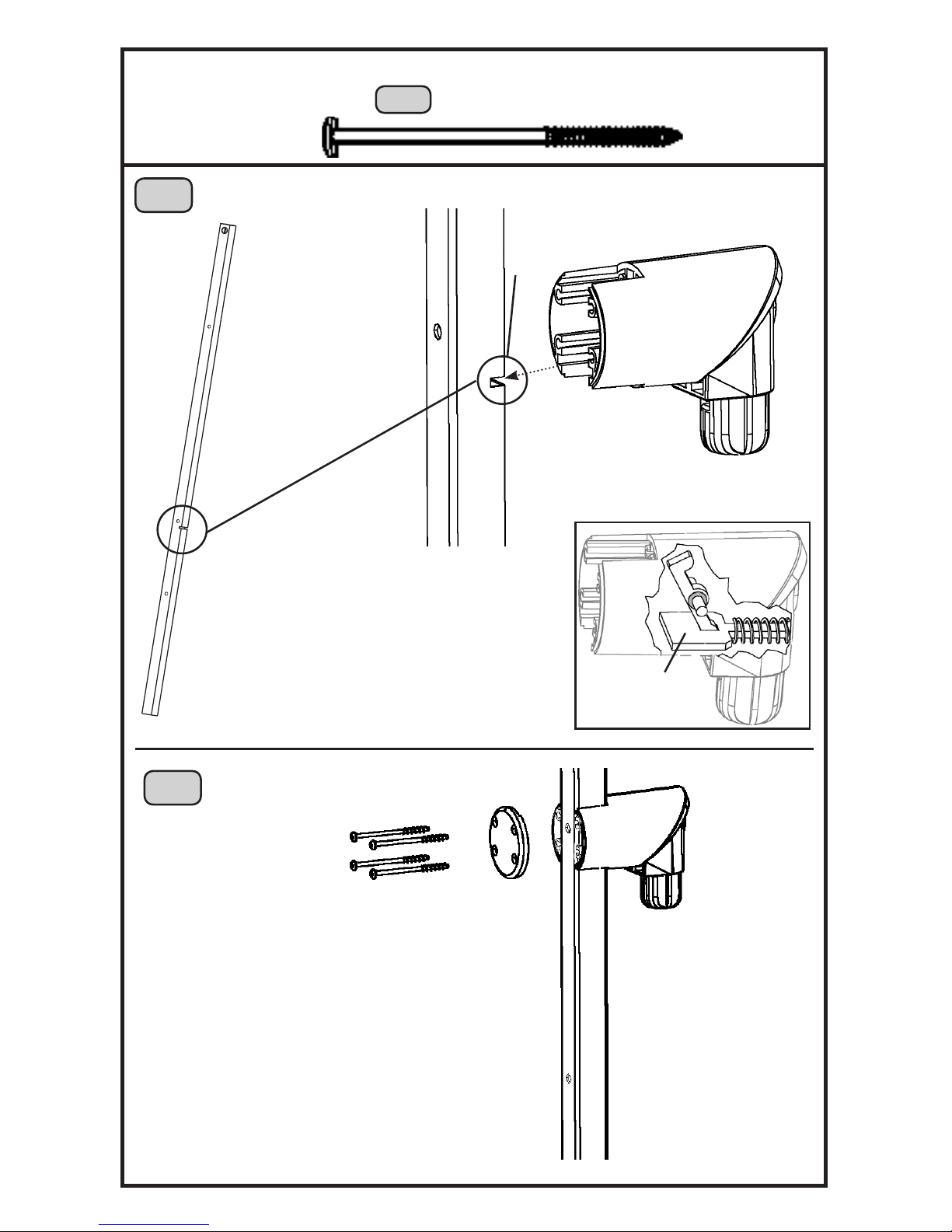
14
Screwdriver
Required For This Page:
1028796
SD
(4)
SD
SE
AO
Fit the Lock Tab (SH) into slot in Outer Tube (AO).
18
AO
Slot
Pre-assembled
Upper Handle
19
AO
SH

15
While pressing the button on the Handle, slide the Inner Fast Track
Channel (AN) into the Outer Fast Track Tube (AO).
20
SF
SC
21
SD
SE
22
AO
AN
Press button while
inserting Channel.
End with hole.
Be sure that side
with notches
faces up.
Screwdriver
Required For This Page:
1028796
SD
(4)
AB
16
1/2” Wrenches
Required For This Page:
ME
MF
(1)
(1)
MH
MG
(2)
(2)
MJ
(4)
1024989
3/4” Wrenches
AE
MH
AF
**2 ADULTS REqUIRED FOR THIS
STEP**
MG
23
The Backboard and Rim should be on
the ground resting on cardboard with the
Extension Arms facing up.
The Backboard must face the
opposite direction as the Pole
Bracket.
TP
MH
ME
MF
Tighten the Nuts (MF & MB) securely.
24
WARNING
Do not overtighten the Cap Nut. If the end of the Bolt breaks through the plastic cap,
call our Customer Service Department at the number on Page Two. Exposed threads on
the end of the Bolt may cause serious injuries such as those listed on Page Two.
MG
Tighten the Nuts until
they are ush with the
ends of the Bolts.
MJ
6 5/8”
(Not actual length)
AF
AE

17
Required For This Page:
MH
MG
(1)
3/4” Wrenches
6 5/8”
(Not actual length)
25
MD
(2)
Tighten all Nuts
securely now.
MA
ML
(1)
(1)
6 1/2”
(Not actual length)
9/16” Wrenches
26
ML
Use the holes
closest to the
pole.
MA
Remove the plastic lm
from the Backboard.
Tighten all Nuts
securely now.
Attach the Outer Tube (AO) to the Long Extension Arms (AE).
1024989
(1)
MC
(1)
MB
(1)
MB
MC
MH
MG
MD
TP
AE
AE
AO

18
Use the closed end of a
wrench to pull the Springs up
and over the Bolt.
27
AD
28
Insert one of the 1 1/4” Base Plugs (AM)
into the lower hole in the Base.
Hook the Spring (AD) onto the Spacer between the Backboard
Brackets and hook the other end over the Bolt installed in the
previous step.
AM

19
Never put the system in an upright position without proper weight in the Base. The
system may fall over and could result in serious personal injury or property damage.
For safety reasons, we recommend lling the base with sand, not water.
WARNING
Using a funnel, add sand through the hole in the top of the Base
until it is just below the top hole (Fig. 1).
FILLING WITH SAND:
FILLING WITH WATER:
Add water through the top hole in the Base until the water is just below the
top hole (Fig. 1).
Figure 2
Figure 1
Figure 2
Insert the remaining
Base Plug (AM) into the
top ll hole.
One adult needs to hold down the Pole while the Base is
being lled.
Figure 1
Insert the remaining
Base Plug (AM) into the
top ll hole.
Finish lling the Base
with water (Fig 2).
Using two adults, carefully stand the system up.
Add one tablespoon of chlorine bleach to the water in the Base.
Finish lling the Base
with sand (Fig. 2).
You will need 362 lb. of sand to ll the Base.
Using two adults, carefully stand the system up.
29

20
31
Pull the Handle all the way down so the system is at the highest
setting.
AY
30
Attach the Pole Pad (AI) to the pole.
AI
Lay the Pole Pad (AI) at on the ground and stick the extra Warning
Sticker (AU) to the Pole Pad below the Logo.
AI
AU
Smooth out any air bubbles in the Sticker.
Top strap of the Pole Pad should go around the
pole just above the Pole Bracket (AT).
AT
8’
8.5’
9’
9.5’
10’
Line up the 10’ mark on the Height
Sticker (AY) with the bottom edge of the
Fast Track Handle and apply the Sticker
to the back of the pole as shown.

21
Only clean the Backboard with the approved
cleaning materials listed below:
The use of other chemicals will void the warranty.
1
Registered Trademark of the Drackett Products Company.
2
Registered Trademarks of Procter & Gamble.
3
Registered Trademark of Texize, Division of Norton Norwich Products Inc.
4
Registered Trademark of the Clorox Company.
Windex
1
Joy2
Mr. Clean
2
Fantastik
3
Formula 409
4
When using water in the Base, take these precautions:
1. Make sure the surface beneath the Base is smooth and free of stones, gravel or sharp objects
that could puncture the Base and cause leakage.
2. Check the Base frequently for cracks or punctures.
3. Always check the water level before play.
4. If the system is to be stored without weight, tilt it forward and rest the Rim on the ground.
5. EverytimetheBaseislledwithwater,addonetablespoonofchlorinebleachtothewater
to prevent algae formation in the Base.
WHILE TRANSPORTING THE PORTABLE SYSTEM, USE
CAUTION TO PREVENT THE MECHANISM FROM ADJUSTING.
Please call our Customer Service Department at the number on Page Two to
obtain replacement Nets. Our Nets are shorter than average to reduce the risk
of entanglement.
32
RI
Insert Net (RI) between metal loops of Nethook.
After threading Cord around Rim, tie ends of Cord together at
the back of the Rim with a secure knot.
Thread the Net Cord (NC) through Nethook and Net (RI).
NC

22
The life of your basketball system depends on many variables. The climate, exposure to
corrosives such as salt, pesticides, or herbicides, and excessive use or misuse can all
contribute to pole failure, which may cause property damage or personal injury.
Check your basketball system frequently for loose hardware, excessive wear, and signs of
corrosion. For safety reasons, and to prolong the life of your basketball system, you must
take the following preventive measures.
a. Check all Nuts and Bolts. If any are loose, tighten them.
b. Check all parts for excessive wear and tear. If necessary, replace any parts that have
been worn or damaged through usage. Contact our Customer Service Department for
replacement parts.
c. Inspect the Warning Sticker on the pole. If it is ripped, faded, or illegible, call our Customer
Service Department to request a replacement Sticker.
d. Check all pole sections for visible rust or chipped or cracked paint. If either are present,
do the following:
1. Use an emery cloth to completely remove any rust or chipped paint.
2. Clean the area with a damp cloth and allow it to dry.
3. Apply two coats of a rust preventative, high gloss enamel paint to the area. Allow
the paint to dry between coats.
IF RUST HAS PENETRATED THROUGH THE POLE ANYWHERE,
REPLACE IT IMMEDIATELY!
POLE CARE AND SYSTEM MAINTENANCE
Moving the system
WARNING: e system must only be moved by people capable of handling its weight.
Children should not be allowed to move the system.
a. Adjust the system to its lowest position.
b. Stand in front of the system and pull on the pole until the unit is balanced on its Wheels.
c. Move the system to the desired location and carefully set the Base down.
Operation of the height adjustment system
The adjustable system may be adjusted from 7 1/2 feet to 10 feet in 6-inch
increments. Hold the Handle tightly and push the button. Raise the Handle to
lower the Backboard, or lower the Handle to raise the Backboard.
While transporting the portable system, use caution to
prevent the mechanism from adjusting.

23
FAUTE DE NE PAS SUIVRE CES AVERTISSEMENTS, VOUS
RISQUEZ DE CAUSER DES BLESSURES GRAVES ET/OU
DES DOMMAGES À L’ÉQUIPEMENT.
SI NO SE OBEDECEN ESTAS ADVERTENCIAS PUEDEN
PRODUCIRSE GRAVES LESIONES y/O DAñOS A LA
PROPIEDAD.
Le propriétaire doit s’assurer que tous les joueurs connaissent
et appliquent les règles suivantes an d’utiliser l’équipement en
toute sécurité.
WARNING
El propietario del sistema debe asegurarse de que todos
los jugadores conozcan y respeten estas reglas para que el
sistema se use en forma segura.
FAILURE TO FOLLOW THESE WARNINGS MAy RESULT IN
SERIOUS INJURy AND/OR PROPERTy DAMAGE.
Owners must ensure that all players know and follow these
rules for safe operation of the system.
Only hang from the rim briey to regain balance or avoid injuring
others. Release the rim as soon as safely possible.
During play, especially when performing dunk type activities, keep
player’s face away from the backboard, rim, and net. Serious injury
could occur if teeth/face come in contact with the backboard, rim,
or net. Player should wear a mouth guard during play.
Do not slide, climb, or play on base or pole.
Completely ll base according to manufacturer ’s instructions.
Never leave the unit standing in an upright position without rst
lling the base with weight or the system will tip quickly causing
serious personal injury.
When adjusting height or moving system, keep hands and ngers
away from moving parts.
Do not allow children to move or adjust system.
Do not wear jewelry (rings, watches, necklaces, etc.) during play.
Objects may entangle in net.
Keep organic material away from pole base. Grass, litter, etc. could
cause corrosion and/or deterioration.
• Cuélguese del aro sólo en forma breve, para recuperar el
equilibrio o evitar lesionar a otros jugadores. Suéltese del aro lo
más pronto que pueda hacerlo con seguridad.
• Durante el juego, especialmente al embocar violentamente
de alto, la cara de los jugadores debe mantenerse alejada del
tablero, el aro y la red. Pueden producirse lesiones graves si los
dientes o la cara entran en contacto con el tablero, el aro o la red.
Los jugadores deben usar un protector bucal durante el juego.
• No se deslice, no trepe ni juegue sobre la base o el poste.
• Llene la base completamente siguiendo las instrucciones del
fabricante. Nunca deje la unidad en posición de uso sin haber
llenado previamente la base con material de contrapeso, pues el
sistema podría tumbarse rápidamente y causar graves lesiones
personales.
• Mantenga las manos y los dedos alejados de las piezas movibles
cuando regule la altura o desplace el sistema.
• No deje que los niños regulen ni desplacen el sistema.
• No use joyas (anillos, relojes, collares o gargantillas, etc.)
durante el juego. Estos objetos pueden engancharse en la red.
• La supercie donde se coloque la base debe estar lisa y
desprovista de piedras, grava u otros objetos. Las perforaciones
pueden originar pérdidas, y éstas pueden hacer que el sistema
se tumbe.
• No permita que la base del poste entre en contacto con
materiales orgánicos. El pasto, los desechos animales, etc.,
pueden causar corrosión y/o deterioros.
• Controle el poste y todas las piezas metálicas una vez al mes
en busca de signos visibles de corrosión (oxidación, picaduras,
escamado). Elimine todo rastro de óxido y vuelva a pintar con
esmalte para exteriores. Si el óxido ha penetrado cualquier pieza
de acero, reemplace esa pieza de inmediato.
• Inspeccione el sistema antes de cada uso para vericar que
esté adecuadamente contrapesado, que los elementos de jación
no estén ojos, que no haya desgaste excesivo, inestabilidad
ni signos de corrosión. Si encuentra irregularidades, repárelas
antes de usar el sistema.
Nunca juegue con un equipo dañado.
• No use el sistema en presencia de vientos fuertes o condiciones
climáticas adversas, ya que puede tumbarse. Coloque la unidad
en su posición de almacenamiento y/o en una zona a resguardo
del viento, lejos de propiedades personales que puedan dañarse
si el sistema se cae, y de líneas de suministro de energía.
• No use el sistema para levantar ningún objeto. El mecanismo
está diseñado para elevar solamente el peso del tablero con el
aro. No cuelgue nada de la agarradera, el aro, el tablero ni los
brazos de elevación, ya que esto puede dañar el sistema y anular
la garantía.
• Ne vous suspendez pas à l’anneau plus que nécessaire pour
retrouver votre équilibre ou éviter de blesser les autres joueurs.
Relâchez l’anneau aussitôt que possible.
• Lors d’un match, particulièrement dans le cas des smashs, le
visage du joueur ne doit pas faire face au panneau, à l’anneau,
ni au let. Le joueur risque de graves blessures si ses dents ou
son visage entrent en contact avec le panneau, l’anneau, ou le
let. Les joueurs doivent toujours porter un protège-dents lorsqu’ils
jouent.
• Ne glissez pas, ne grimpez pas, et ne jouez pas sur la base ou
le poteau.
• Remplissez complètement la base selon les instructions du
fabricant. Ne laissez jamais l’unité debout de plein pied sans avoir
d’abord rempli la base avec un poids ou l’équipement pourrait
basculer rapidement et causer de graves blessures.
• Lorsque vous ajustez la hauteur ou lorsque vous déplacez
l’équipement, gardez vos mains et doigts loin des pièces mobiles.
• Ne permettez pas aux enfants de déplacer ou d’ajuster
l’équipement.
• Ne portez pas de bijoux (bagues, montres, colliers, etc.) lorsque
vous jouez. Ces objets pourraient s’accrocher au let.
• La surface sur laquelle est posée la base doit être lisse et sans
gravier ou tout autre objet qui pourrait trouer la base entraînant
ainsi une fuite ce qui pourrait faire basculer l’équipement.
• La base ne doit pas non plus être posée sur aucun type de
matière organique. L’herbe, les déchets, etc. peuvent entraîner la
corrosion et la détérioration de l’équipement.
• Une fois par mois, vériez que le Poteau et toutes les pièces
en métal ne montrent pas de signes de corrosion (rouille, piqûres,
écaillage). Enlevez toute la rouille et repeignez complètement
avec une peinture pour extérieur. Si la rouille a pénétré une des
pièces en acier, vous devrez remplacer immédiatement la pièce
en question.
• A chaque fois que vous allez utiliser l’équipement, vériez d’abord
l’équilibre, la possibilité de pièces desserrées ou usées, la stabilité
de l’équipement et tout signe de corrosion ou réparation nécessaire
avant utilisation.
• Ne jouez jamais avec un équipement endommagé.
• N’utilisez pas l’équipement lors de fortes rafales de vent ou
de mauvais temps. L’équipement pourrait basculer. Placez
l’équipement dans un endroit abrité du vent ou loin des structures
qu’il pourrait endommager s’il basculait et loin des ls électriques.
• N’utilisez pas l’équipement pour lever ou soulever quoique ce
soit. Son mécanisme a été conçu uniquement pour soutenir le
poids du panneau et de l’anneau. N’accrochez rien au manche,
à l’anneau, au panneau ni aux leviers sous peine d’endommager
l’équipement et d’annuler la garantie.
ADVERTENCIA
AVERTISSEMENT
#FS16400
10/12/2004
www.lifetime.com
Surface beneath the base must be smooth and free of gravel or
other objects. Punctures cause leakage and could cause system
to tip over.
Once a month check pole and all metal parts for signs of corrosion
(rust, pitting, chipping). Completely remove rust and repaint with
exterior enamel. If rust has penetrated any steel part, replace that
part immediately.
Check system before each use for proper ballast, loose hardware,
excessive wear, instability, and signs of corrosion and repair
before use.
Never play on damaged equipment.
Do not use system during windy or severe weather. System may
tip over. Place system in an area protected from the wind or in an
area away from property that may be damaged if the system falls,
and from overhead power lines.
Do not use the system to lift or hoist anything. The mechanism is
designed to lift only the weight of the backboard and rim. Do not
hang anything from the handle, rim backboard, or lifter arms as
this will damage the system and void the warranty.

LIFETIME BASKETBALL EQUIPMENT
6-YEAR LIMITED FACTORY WARRANTY
THE MANUFACTURER RESERVES THE RIGHT TO MAKE SUBSTITUTIONS TO
WARRANTY CLAIMS IF PARTS ARE UNAVAILABLE OR OBSOLETE.
1. Lifetime basketball systems are warranted to the original purchaser to be free from defects
in material or workmanship for a period of six years from the date of original retail purchase.
The word “defects” is dened as imperfections that impair the use of the product. Defects
resulting from misuse, abuse or negligence will void this warranty. This warranty does not
cover defects due to improper installation, alteration or accident. This warranty does not
cover damage caused by vandalism, rusting, “acts of nature” or any other event beyond the
control of the manufacturer.
2. This warranty is nontransferable and is expressly limited to the repair or replacement of
defective basketball equipment. If the equipment is defective within the terms of this warranty,
Lifetime Products, Inc. will repair or replace defective parts at no cost to the purchaser. Shipping
charges to and from the factory are not covered and are the responsibility of the purchaser.
Labor charges and related expenses for removal, installation or replacement of the basketball
system or its components are not covered under this warranty.
3. This warranty does not cover scratching or scufng of the product that may result from
normal usage. In addition, defects resulting from intentional damage, negligence, unreasonable
use or hanging from the net or rim will void this warranty.
4. Liability for incidental or consequential damages is excluded to the extent permitted by
law. While every attempt is made to embody the highest degree of safety in all equipment,
freedom from injury cannot be guaranteed. The user assumes all risk of injury resulting from
the use of this product. All merchandise is sold on this condition, and no representative of
the company may waive or change this policy.
5. This product is not intended for institutional or commercial use; Lifetime Products, Inc. does not
assume any liability for such use. Institutional or commercial use will void the warranty.
6. This warranty is expressly in lieu of all other warranties, expressed or implied, including
warranties of merchantability or tness for use. Neither Lifetime Products, Inc., nor any
representative assumes any other liability in connection with this product.
ALL WARRANTY CLAIMS MUST BE ACCOMPANIED BY A SALES RECEIPT.
To register the product, visit our Web site at www.lifetime.com
REPORT PRODUCT DEFECTS IN WRITING TO:
Lifetime Products, Inc., MC Box 160010 Cleareld, UT 84016-0010 or
call (800) 225-3865 M-F 7 a.m. to 5 p.m. MST.
Please include your dated sales receipt and photographs of damaged parts.
WWWLIFETIMECOM
¥,IFETIME0RODUCTS)NC
0/"OXs&REEPORT#ENTER"LDG$#LEARlE
LD5TAH
4s&
 Loading...