

Lifetime A-FRAME PLAYSET 90042, 90240 Assembly Instructions Manual
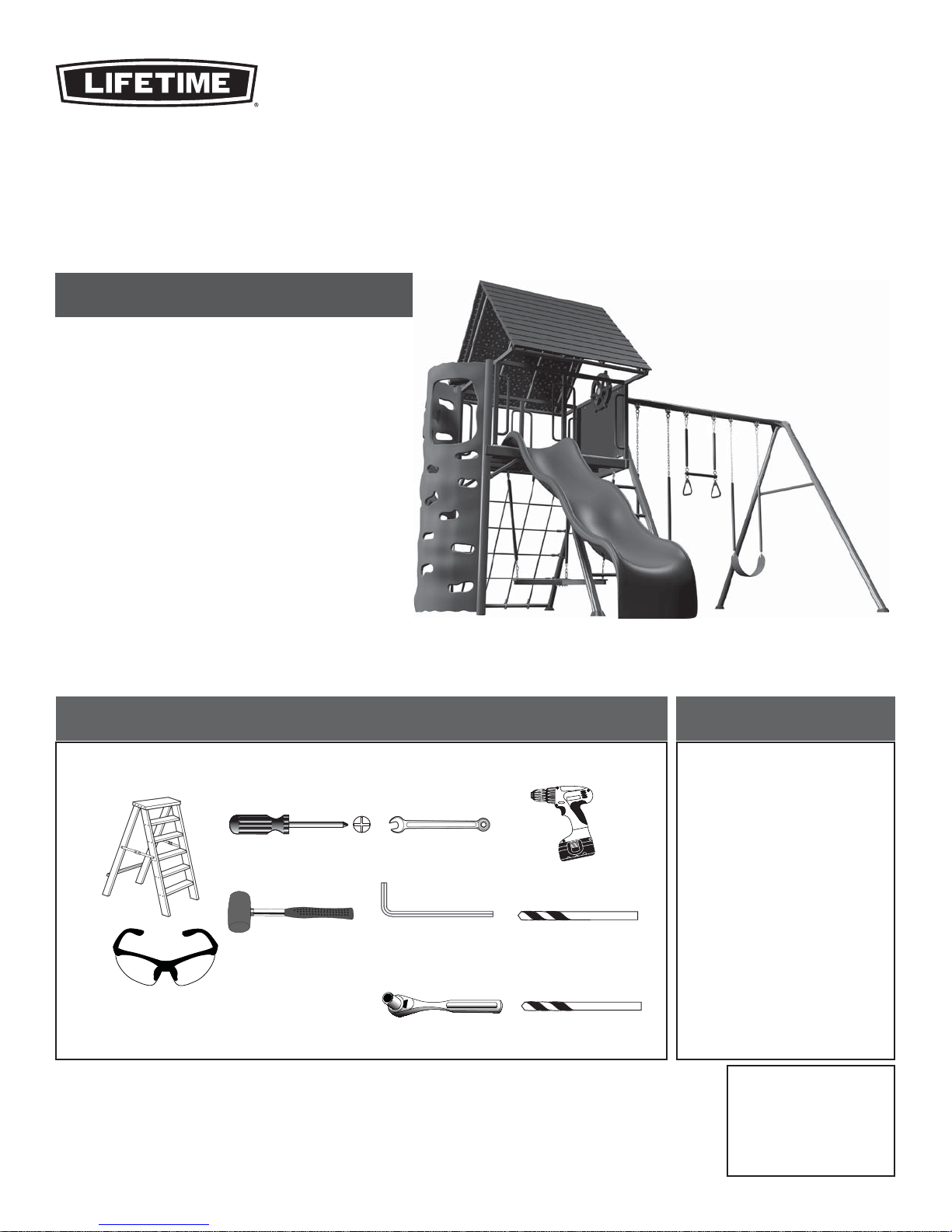
A-FRAME PLAYSET
MODEL #60091
MODEL 90042
• Before you start, prepare a level surface with the proper
Safety Zone (see page 12).
• 2+ people recommended for setup
ASSEMBLY INSTRUCTIONS
Save this instruction in the event that the manufacturer has
to be contacted for replacement parts.
TOOLS REQUIRED
1/2 in/po (≈13 mm)
(1)
(1)
(1)
(2)
3/16 in/po (≈5 mm)
(2, included)
(2)
(1)
(1)
5/16 in/po (≈8 mm)
(1)
1/4 in/po (≈6 mm)
(1)
TABLE OF CONTENTS
Icon Legend................................4
Warnings and Notices..................5
Safety Information.....................6
Safe Play Area..........................12
A-Frame Assembly....................13
Deck Support Assembly.............19
Deck Assembly..........................30
Parts Identifi er.........................i-iv
Climbing Wall and Chalkboard
Assembly................................. 37
Roof Assembly..........................43
Slide and Accessories Assembly ....
...............................................49
Swing Assembly........................55
Maintenance Instructions..........60
Registration..............................63
Warning Sticker........................64
Warranty...................................65
MODEL# AND PRODUCT ID
(you will need both when contacting us)
Model Number: 90042
Product ID:
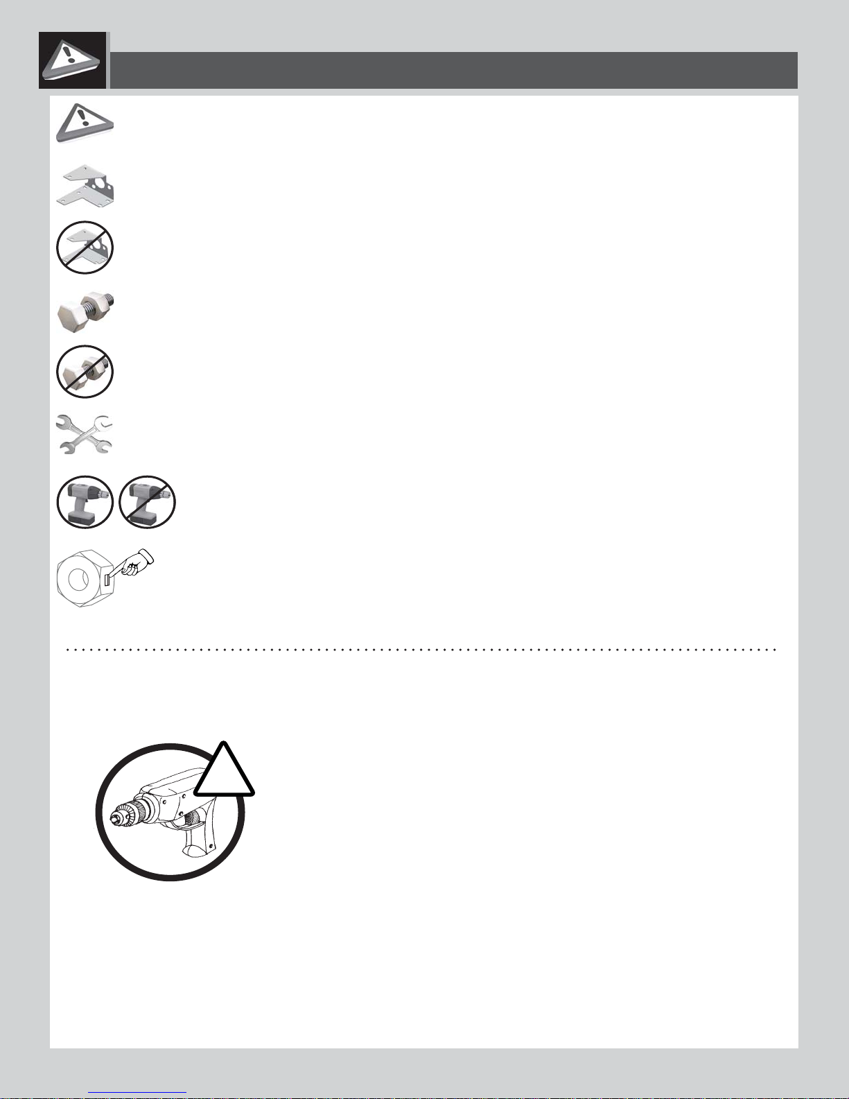
ICON LEGEND
Indicates special heed should be taken when reading.
Indicates the parts to be used for a section.
Indicates no parts required for a specifi c section.
Indicates the hardware to be used for a section.
Indicates no hardware required for a specifi c page.
Indicates the tools to be used for a section.
Indicates to use/not to use an electric drill for a specifi c step.
Indicates the use of a centerlock nut. A nut with this marking will require some effort to tighten. This hardware was
designed with this feature in order to prevent loosening later.
USE A
USING A DRILL IS NOT RECOMMENDED FOR DRIVING BOL
A cordless drill can be used for driving screws;
however, care should be taken not to over
T YOUR OWN RISK!
TS.
-tighten or strip screws.
!
# 1175581_B
12/1/2016
4

W
ARNINGS & NOTICES
SAFETY INSTRUCTIONS
FAILURE TO FOLLOW THESE WARNINGS MAY RESULT IN SERIOUS INJURY OR PROPERTY DAMAGE AND WILL VOID WARRANTY.
Owner must ensure that all players know and follow these rules for safe operation of the system.
To ensure safety, do not attempt to assemble this product without following the instructions carefully. Check entire box and inside all packing
material for parts and/or additional instruction material. Before beginning assembly, read the instructions and identify parts using the hardware
identifi er and parts list in this document. Proper and complete assembly, use and supervision are essential for proper operation and to reduce the
risk of accident or injury. A high probability of serious injury exists if this product is not installed, maintained, and operated properly.
• If using a ladder during assembly, use extreme caution.
• Two capable adults are recommended for this operation.
• Be aware that parts can be damaged by overtightening the screws.
• All who participate in the assembly process should wear safety glasses throughout the assembly.
Most injuries are caused by misuse and/or not following instructions. Use caution when using this product.
5

**IMPORTANT SAFETY INFORMATION**
PLEASE READ BEFORE BEGINNING ASSEMBLY:
INSTALLATION & GROUND PREPARATION INSTRUCTIONS
• Place the equipment on a level, well-drained ground, not less than 6.6 ft (2.0 m) from any structure or obstruction such as a fence, garage, house, overhanging branches, laundry lines, or electrical
wires
• Provide enough room so that children can use the equipment safely. For example, for structures
with multiple play activities, a slide should not exit in front of a swing.
• Separate active and quiet activities from each other. For example, locate sandboxes away from
swings or use a guardrail or barrier to separate the sandbox from the movement of the swings.
• Do not install home playground equipment over concrete, asphalt, packed earth, grass, carpet, or any
other hard surface. A fall onto a hard surface can result in serious injury to the equipment user (see page 7).
• To prevent serious injury, warn children that they must not use the equipment until properly installed.
• Create a site free of obstacles that could cause injuries – such as low overhanging tree branches,
overhead wires, tree stumps and/or roots, large rocks, bricks, and concrete.
• Choose a level location for the equipment. This can reduce the likelihood of the play set tipping
over and loose-fi ll surfacing materials washing away during heavy rains.
PLAYGROUND AND SURFACE MATERIALS INSTRUCTIONS
• Use containment, such as digging out around the perimeter and/or lining the perimeter with landscape edging.
• Do not install loose fi ll surfacing over hard surfaces such as concrete or asphalt.
• Installations of rubber tiles or poured-in-place surfaces (other than loose-fi ll materials) generally
require a professional and are not “do-it yourself” projects.
• Use Playground Surfacing Materials (other than loose-fi ll material) which comply to the safety standard
ASTM F1292 Standard Specifi cation for Impact Attenuation of Surfacing Materials within the Use Zone of
Playground Equipment.
OPERATING INSTRUCTIONS
Observing the following instructions and warnings reduces the likelihood of serious or fatal injury:
• The maximum number of occupants that may safely use the entire play set including all
components is eight with a maximum weight of 900 pounds (408 kg).
• On-site adult supervision should be provided for children of all ages.
• Instruct children not to walk close to, in front of, behind, or between moving items.
• Do not move the equipment while it is in use.
• Instruct children not to twist swing chains or ropes or loop them over the top support bar since this
may reduce the strength of the chain or rope.
• Instruct children to avoid swinging empty seats.
• Teach children to sit in the center of the swings with their full weight on the seats.
• Instruct children not to use the equipment in a manner other than intended.
• Instruct children not to get off the equipment while it is in motion.
• To prevent entanglement and strangulation, dress children appropriately using well-fi tting shoes
and avoiding ponchos, scarves, jackets with neck drawstrings, helmets with straps, and other loosefi tting clothing that is potentially hazardous while using equipment.
• Instruct children not to play when the equipment is wet.
• Instruct children not to attach items to the playground equipment that are not specifi cally designed
for use with the equipment, such as, but not limited to, jump ropes, clothesline, pet leashes, cables
and chain as they may cause a strangulation hazard.
• Place the equipment no less than 6.6 ft. (2.0 m) from any structure or obstruction such as a fence,
garage, house, overhanging branches, laundry lines, or electrical wires.
• Impact surfacing needs to cover the entire recommended play area.
6
CONSUMER INFORMATION SHEET FOR PLAYGROUND SURFACING MATERIALS*
Select Protective Surfacing—One of the most important things you can
do to reduce the likelihood of serious head injuries is to install shockabsorbing protective surfacing under and around your play equipment.
The protective surfacing should be applied to a depth that is suitable for
the equipment height in accordance with ASTM Specifi cation F1292.
There are different types of surfacing to choose from; whichever product
you select, follow these guidelines:
Loose-Fill Materials—Maintain a minimum depth of 9 inches of loosefi ll
materials such as wood mulch/chips, engineered wood fi ber (EWF), or
shredded/recycled rubber mulch for equipment up to 8 feet high; and
9 inches of sand or pea gravel for equipment up to 5 feet high. NOTE:
An initial fi ll level of 12 inches will compress to about a 9-inch depth of
surfacing over time. The surfacing will also compact, displace, and settle,
and should be periodically refi lled to maintain at least a 9-inch depth.
Use a minimum of 6 inches of protective surfacing for play equipment
less than 4 feet in height. If maintained properly, this should be
adequate. (At depths less than 6 inches, the protective material is too
easily displaced or compacted.)
NOTE: Do not install home playground equipment over
concrete, asphalt, or any other hard surface. A fall onto a hard surface
can result in serious injury to the equipment user. Grass and dirt are not
considered protective surfacing because wear and environmental factors
can reduce their shock absorbing effectiveness. Carpeting and thin mats
are generally not adequate protective surfacing. Ground level equipment
– such as a sandbox, activity wall, playhouse or other equipment that has
no elevated play surface – does not need any protective surfacing.
Use containment, such as digging out around the perimeter and/or lining
the perimeter with landscape edging. Don’t forget to account for water
drainage.
Check and maintain the depth of the loose-fi ll surfacing material. To
maintain the right amount of loose-fi ll materials, mark the correct level
on play equipment support posts. That way you can easily see when to
replenish and/or redistribute the surfacing.
Do not install loose fi ll surfacing over hard surfaces such as concrete or
asphalt.
Poured-In-Place Surfaces or Pre-Manufactured
Rubber Tiles—You may be interested in using surfacing other than loosefi ll materials – like rubber tiles or poured-in-place surfaces.
Installations of these surfaces generally require a professional and are not
“do-it-yourself” projects.
Review surface specifi cations before purchasing this type of surfacing.
Ask the installer/manufacturer for a report showing that the product has
been tested to the following safety standard: ASTM F1292 Standard
Specifi cation for Impact Attenuation of Surfacing Materials within the
Use Zone of Playground Equipment. This report should show the specifi c
height for which the surface is intended to protect against serious head
injury. This height should be equal to or greater than the fall height –
vertical distance between a designated play surface (elevated surface for
standing, sitting, or climbing) and the protective surfacing below – of your
play equipment.
Check the protective surfacing frequently for wear.
Placements—Proper placement and maintenance of protective surfacing
is essential. Be sure to:
Extend surfacing at least 6.6 feet (2 m) from the equipment in all
directions.
For to-fro swings, extend protective surfacing in front of and behind the
swing to a distance equal to twice the height of the top bar from which
the swing is suspended.
For tire swings, extend surfacing in a circle whose radius is equal to
the height of the suspending chain or rope, plus 6.6 feet (2 m) in all
directions.
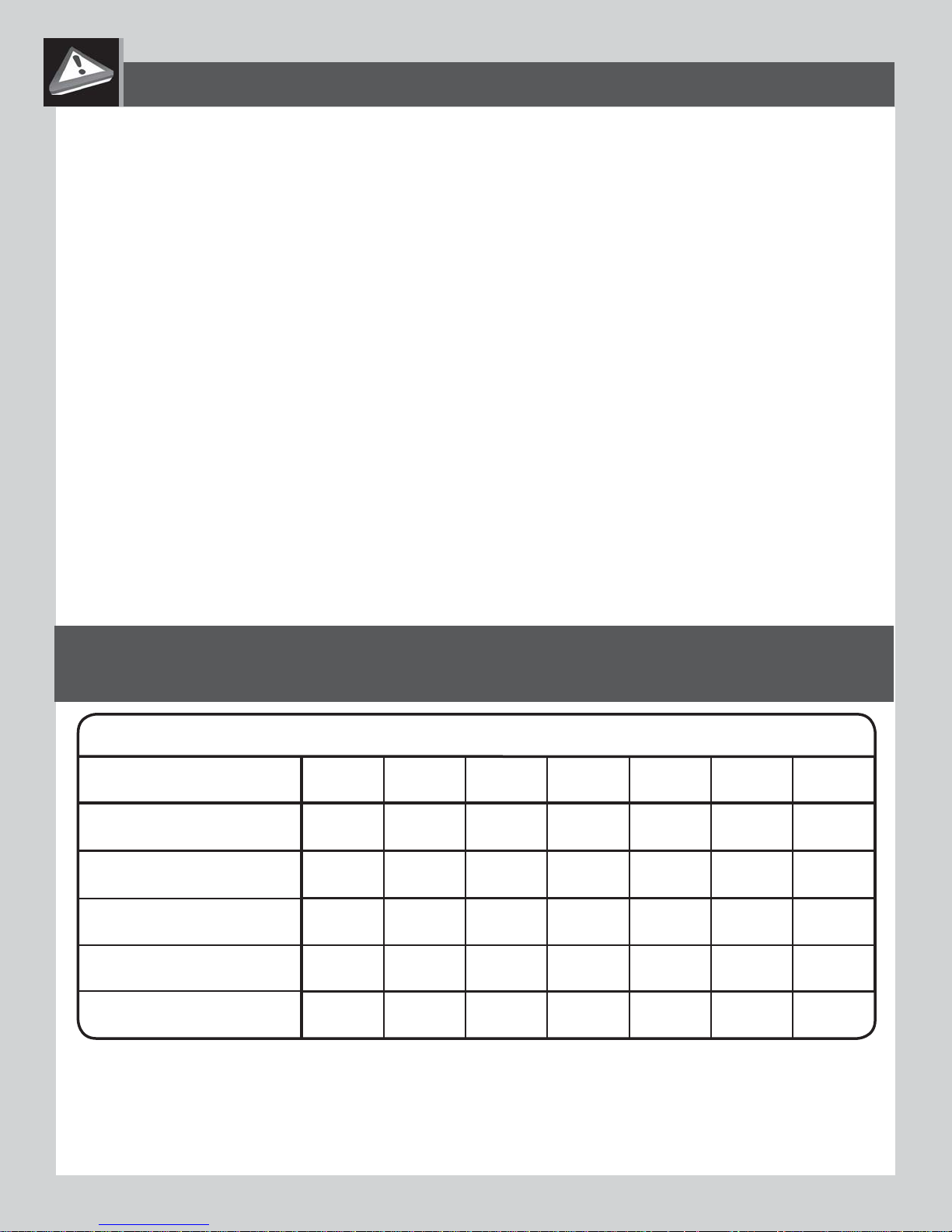
**The maximum fall height for this product is 108 in (274 cm).
We recommend using 9 in (23 cm) of Double Shredded Bark Mulch.**
TABLE 1 — Depth of Surfacing Material Required Based on Fall Heights
Material / Fall Height
Double Shredded Bark
Mulch
Wood Chips
Fine Sand
Fine Gravel
Shredded Tires***
*This information has been extracted from the CPSC publications “Playground Surfacing--Technical Information Guide” and
“Handbook for Public Playground Safety.”
***This data is from tests conducted by independent testing laboratories on a 6-inch depth of uncompressed shredded tire
samples produced by four manufacturers. It is recommended that persons seeking to install shredded tires as a protective surface
request test data from the supplier showing the critical height of the material when it was tested in accordance with ASTM F1292.
5 ft 6 ft 7 ft 9 ft 10 ft 11 ft 12 ft
(152 cm)
(183 cm) (213 cm)
(274 cm)
-- 6 in -- -- 9 in 12 in --
(15 cm)
-- 6 in 9 in -- -- -- 12 in
(15 cm) (23 cm) (30 cm)
6 in -- 9 in 12 in -- -- --
(23 cm)(15 cm)
(30 cm)
-- 6 in 9 in -- 12 in -- --
(15 cm)
(23 cm)
-- -- -- -- 6 in -- --
(305 cm) (335 cm) (366 cm)
(23 cm) (30 cm)
(30 cm)
(15 cm)
7
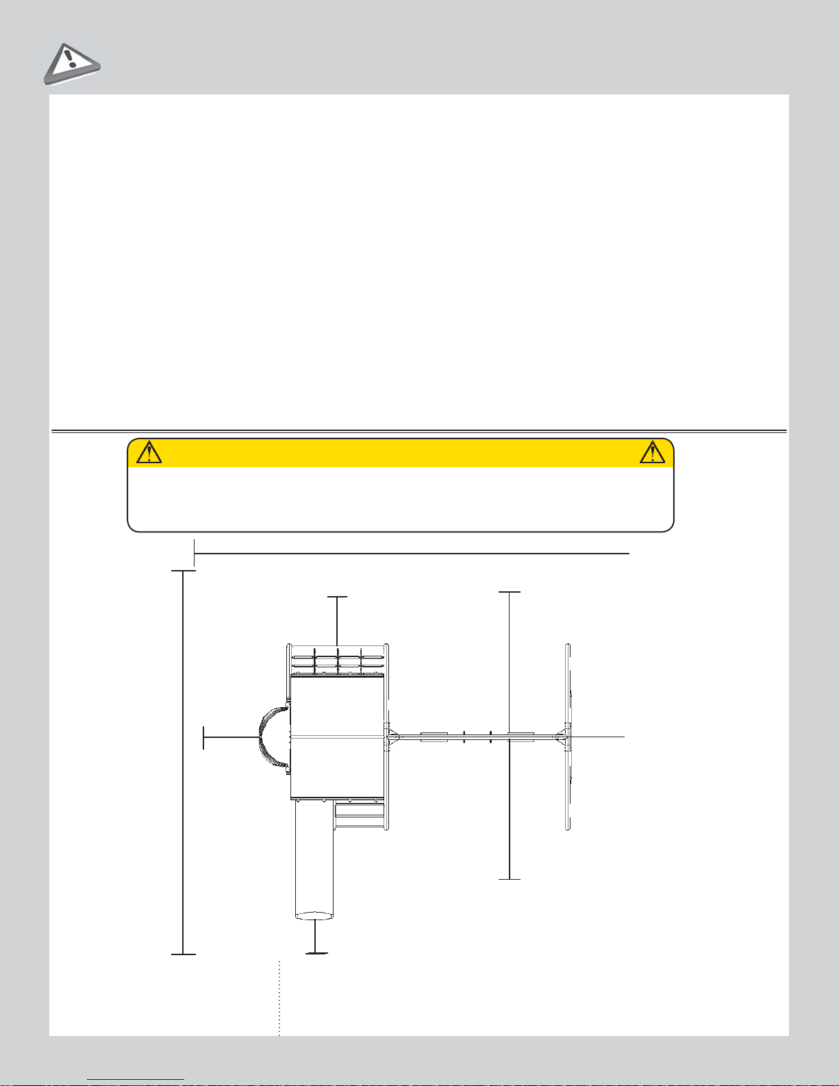
SAFE PLAY AREA
SAFETY ZONE —
Place the equipment no less than 6.6 ft. (2.0 m) from any structure or obstruction
such as a fence, garage, house, overhanging branches, laundry lines, or electrical wires. Make sure
the clearance in front of and behind the swings is at least twice the height of the swing bar. The impact
surfacing needs to cover the entire recommended play area. Refer to the example below.
CAUTION
• Slide can get hot in direct sunlight. It is not recommended that a slide be installed facing south.
6.6 feet
(2,0 m)
29 feet 8 inches (9,04 m)
27 feet 9 inches (8,46 m)
6.6 feet
(2,0 m)
14 feet (4,27 m)
6.6 feet
(2,0 m)
14 feet (4,27 m)
Playset dimensions:
13.11' (4,24 m) x 15.9' (4,8 m)
Recommended play area:
29.8' (9,04 m) x 27.9' (8,46 m)
(2,0 m)
6.6 feet
12
1
A-FRAM
E ASSEMBLY
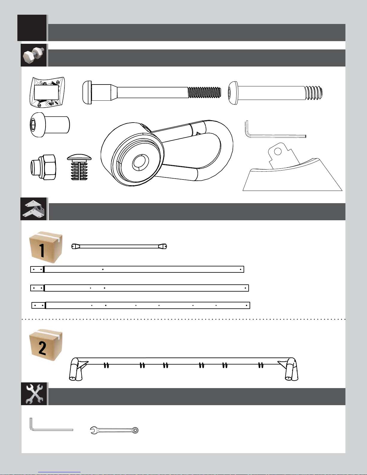
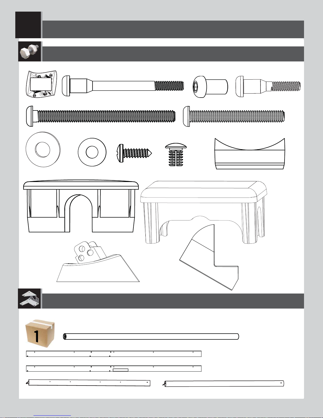
HARDWARE REQUIRED
Hardware Bag / Sac d’accessoires / Bolsa de herraje
CAM
BTS (x10)
AAN (x6)
ARO (x6)
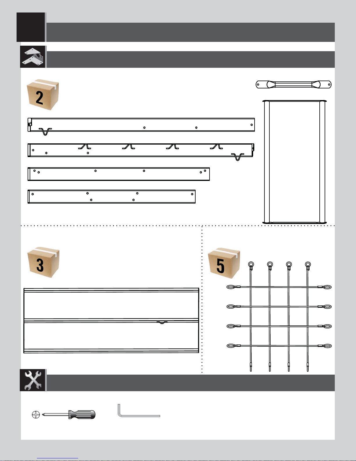
PARTS REQUIRED
CONTENTS OF BOX 1
CBI (x1)
CBG (x2)
DSA (x10)
DZR (x6)
EEO (x2)
DZQ (x6)
BFD (x3)
CBE (x1)
CBF (x1)
CONTENTS OF BOX 2
TOOLS REQUIRED
3/16 in/po (≈5 mm)
(2)
1/2 in/po (≈13 mm)
(1)
CB0 (x1)
13
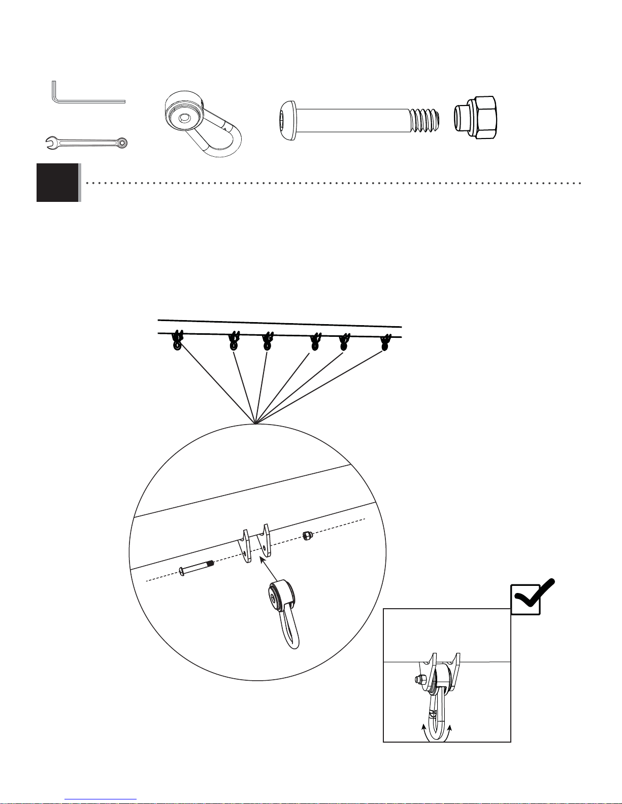
X SECTION 1 (CONTINUED)
TOOLS AND HARDWARE REQUIRED
3/16 in/po (≈5 mm)
(2)
1/2 in/po (≈13 mm)
(1)
DZR (x6)
AAN (x6)
DZQ (x6)
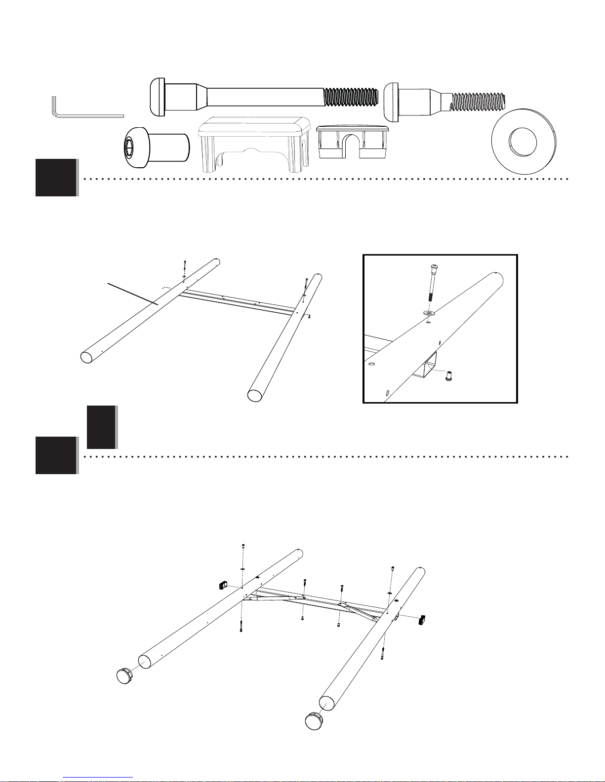
1.1
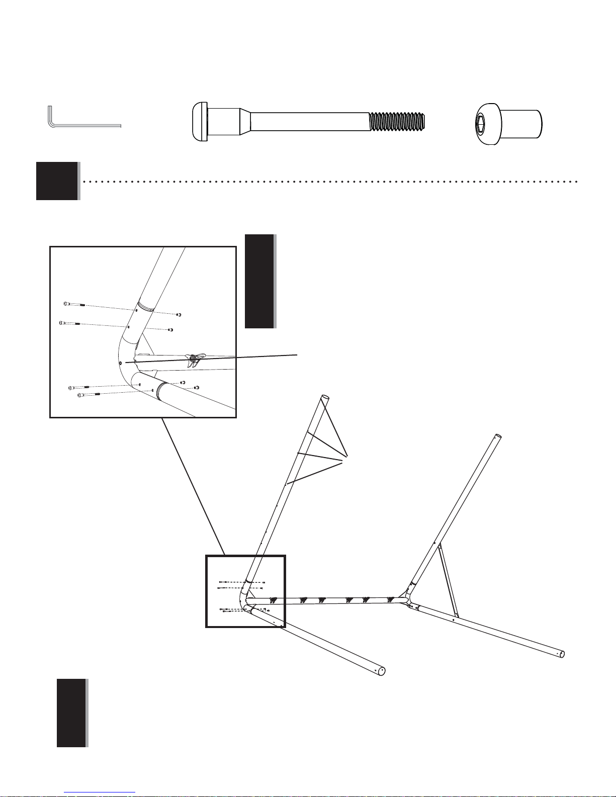
• Attach the Pendulums (DZQ) to the Swing Bar (CB0) using the hardware indicated. Do this for each set of brackets
on the Swing Bar.
CBO
DZR
AAN
DZQ
14
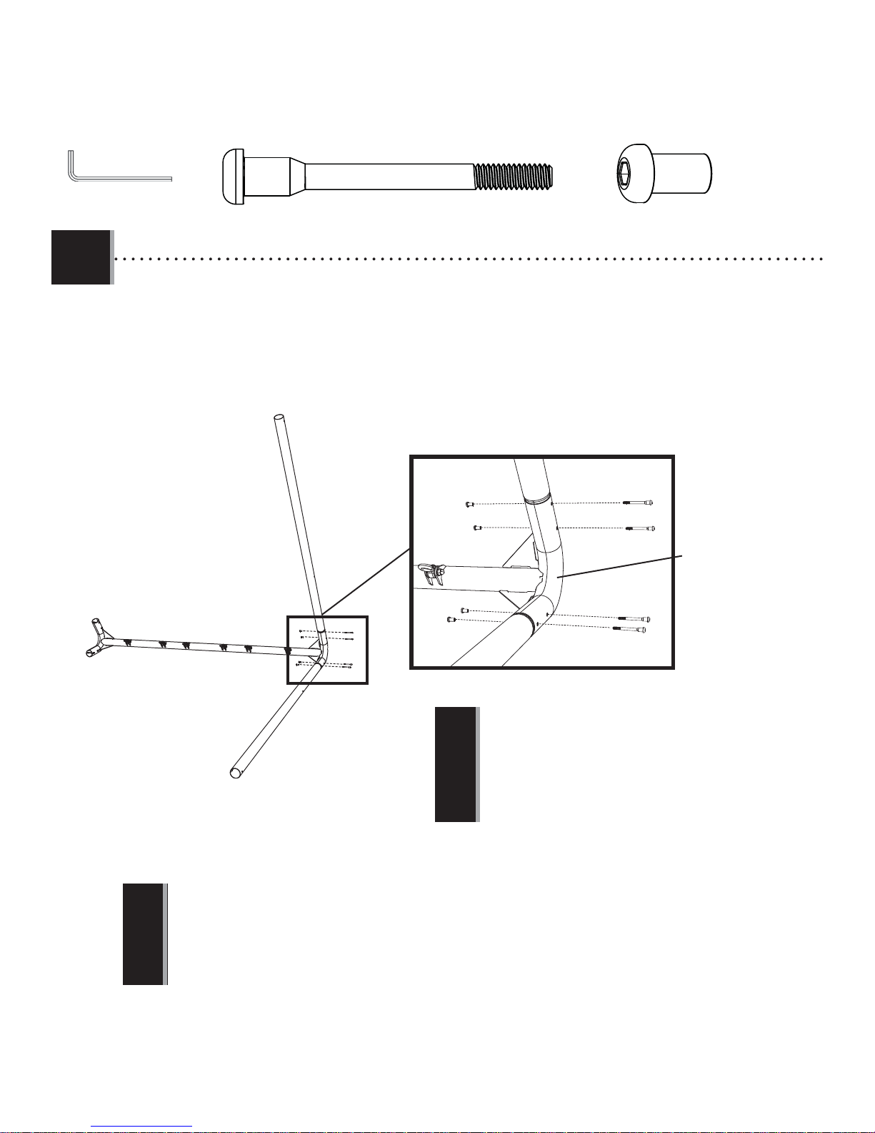
X SECTION 1 (CONTINUED)
TOOLS AND HARDWARE REQUIRED
3/16 in/po (≈5 mm)
6
1.2
(2)
• Insert the two A-Frame Poles (CBG) into the end of the Swing Bar (CBO) that does not have a nut insert in the location
shown, and secure the Poles with the hardware indicated.
CBG
DSA (x4)
BTS
BTS (x4)
DSA
No Nut Insert Here
CBO
• If your A-Frame pole has a dimpled hole, make sure the dimpled
CBG
!
• A band of red tape can be found at the end of the Swing Bar with a nut insert. Make sure this is NOT a nut insert on this end of
the Swing Bar.
!
hole faces away from the Swing Bar.
15
X SECTION 1 (CONTINUED)
TOOLS AND HARDWARE REQUIRED
3/16 in/po (≈5 mm)
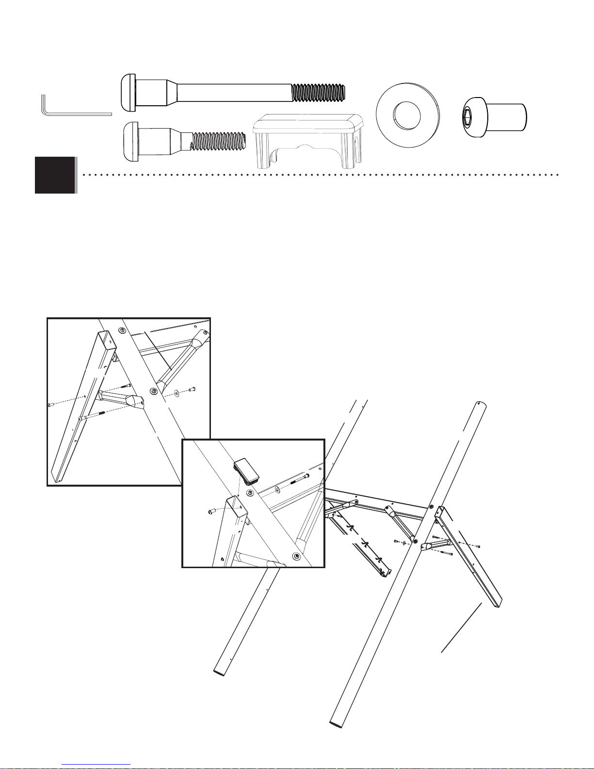
1.3
(2)
• Attach the Turnbar (CBI) to the A-Frame Poles with the hardware indicated.
DSA (x2)
BTS
BTS (x2)
DSA
BTS
CBI
DSA
16
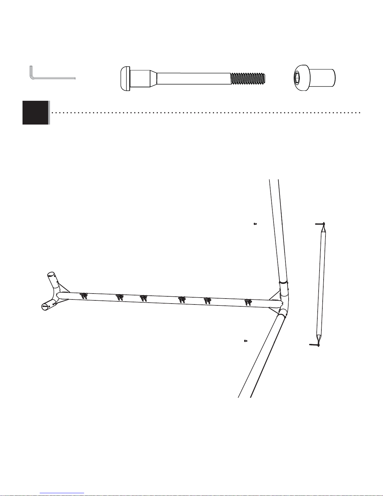
X SECTION 1 (CONTINUED)
TOOLS AND HARDWARE REQUIRED
3/16 in/po (≈5 mm)
1.4
DSA
DSA
DSA
(2)
• Attach the Ladder-side Pole (CBF) and the Net-side Pole (CBE) to the Swing Bar (CBO) in the location indicated.
DSA (x4)
• A band of red tape can be found at the end of the Swing Bar with a nut insert.
Make sure there is a nut insert on this side.
!
DSA
BTS
BTS
Insert Nut Here
BTS
BTS
BTS (x4)
Four holes face out
CBF
CBO
CBE
• Be sure the four holes that run the length of the Ladder-side Pole are facing away from the A-Frame. These holes will be used to
assemble the Ladder later in the assembly.
!
17
X SECTION 1 (CONTINUED)
TOOLS AND HARDWARE REQUIRED
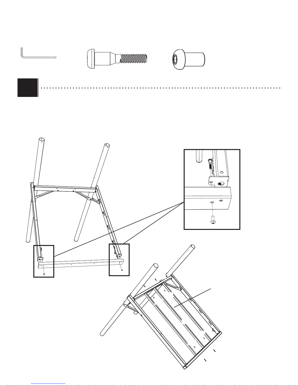
1.5
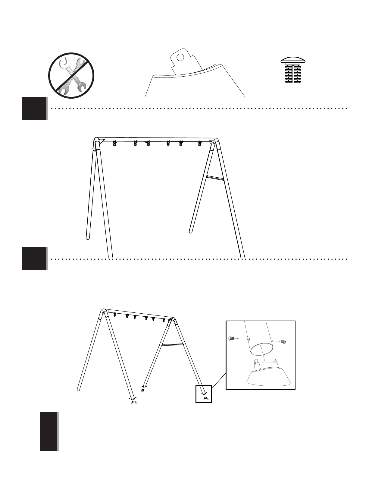
• Using at least two people, slowly rotate the A-Frame assembly upright.
6
ARO (x6)
BFD (x3)
1.6
• Have one person hold the A-Frame assembly steady as another lifts each leg. Attach the A-Frame Foot Caps (BFD)
and secure them with the Cap Plugs (ARO).
ARO
BFD
• Only three of the four poles will receive Foot Caps (BFD) during this step. Do not install a Foot Cap on the Net-side Pole (CBE) until
instructed later in the assembly.
ARO
!
18
2
DECK SUPPORT ASSEMBLY
H
Hardware Bag
CAI
ARDWARE REQUIRED
DSA (x10)
ATV (x2)
AAF (x8) ARL (x3)
ASV (x2)
ARV (x8)
ARO (x2)
EII (x6)
ARU (x1)
BTS (x20)
ARY (x2)
DXY (x10)
BFD (x3)
PARTS REQUIRED
CONTENTS OF BOX 1
CBN (x1)
CBJ (x1)
CBK (x1)
CAZ (x1)
CAC (x2)
CAY (x1)
19
2
DECK SUPPORT ASSEMBLY
PARTS REQUIRED
CONTENTS OF BOX 2
CBC (x1)
CBB (x1)
CBD (x1)
CBP (x4)
CBQ (x2)
CBA (x1)
CONTENTS OF BOX 3
CBL (x1)
CONTENTS OF BOX 5
CBM (x1)
TOOLS REQUIRED
(1)
3/16 in/po (≈5 mm)
(2)
20
X SECTION 2 (CONTINUED)
TOOLS AND HARDWARE REQUIRED
3/16 in/po (≈5 mm)
(2)
DSA (x4)
DXY (x2)
AAF (x4)
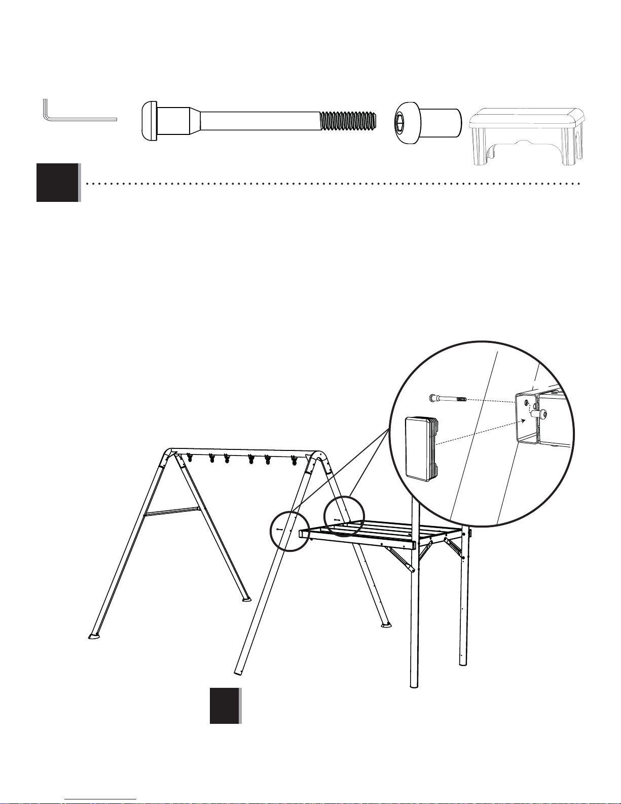
2.1
Warning Sticker
• Attach the Wall-side Deck Support (CBA) to the Left Vertical Pole (CBK) and Right Vertical Pole (CBJ) and secure with the
BTS (x6)
hardware indicated.
CBK
• Make sure the fi ve small holes that run the length of each Vertical Pole are facing each other before completing this step.
EII (x2)
CBA
ASV (x2)
DSA
AAF
CBJ
BTS
!
!
2.2
• Attach two Cross Braces (CBP) to the Left Vertical Pole and Right Vertical Pole in the position indicated and secure
with the hardware indicated.
BTS
BTS
AAF
EII
DSA
ASV
EII
AAF
DSA
CBP
DXY
BTS
DXY
CBP
BTS
ASV
!
21
X SECTION 2 (CONTINUED)
TOOLS AND HARDWARE REQUIRED
6
3/16 in/po (≈5 mm)
(2)
2.3
BTS
DSA (x4)
BTS (x6)
DXY (x2)
• Attach the Deck Support Tube, Net-side (CBB) to the Left Vertical Tube (CBK) using the hardware indicated. Make sure a
Cross Brace (CBP) is secured between the Support Tube and the Vertical Pole. Repeat this step to attach the Deck
Support Tube, Ladder-side (CBC) to the Right Vertical Tube (CBJ) as pictured.
CBP
CBB
DXY
BTS
AAF
DSA
CBK
EII (x2)
CBK
AAF (x4)
CBJ
BTS
CBB
EII
DSA
AAF
CBC
CBB
Hook on Deck Support (CBC) points downward
22
X SECTION 2 (CONTINUED)
TOOLS AND HARDWARE REQUIRED
3/16 in/po (≈5 mm)
(2)
DXY (x6)
6
BTS (x6)
2.4
• Attach the Deck Support Tube, Swing-side (CBD) to the Deck Support Assembly using the hardware indicated. Install
the Inside Deck Support (CBL) in the position indicated and secure with the hardware indicated.
DXY
BTS
CBD
DXY
23
DXY
BTS
Hook on Inside Deck Support points downward
BTS
CBL
BTS
BTS
DXY
DXY
X SECTION 2 (CONTINUED)
TOOLS AND HARDWARE REQUIRED
3/16 in/po (≈5 mm)
2.5
(2)
DSA (x2)
• Attach the Deck Support Assembly to the A-Frame Assembly using the hardware indicated. Insert a Rectangular
Plug (EII) in each end of the Deck Support Tube, Swing-side (CBD) once hardware is secure. Repeat this on the opposite
side of the assembly to secure the Deck Support Assembly to both Poles.
BTS (x2)
DSA
EII (x2)
CBD
BTS
EII
• This step requires two people.
!
24
 Loading...