

Lifetime 90180 Owner's Manual

MODEL N° 90180
COPY
OWNER’S MANUAL
For Customer Service in mainland Europe:
E-mail: cs@lifetimeproducts.eu
Keep this Product ID Number and use when contacting Customer Service:
REGISTER YOUR PRODUCT ONLINE AT WWW.LIFETIME.COM
COPY
At Lifetime®, we are committed to providing innovative and quality products. While registering, you will have the opportunity to give us your feedback. Your
input is valuable to us.
• You can also opt in to receive new product notifi cations or promotions.
• In the unlikely event of a product recall or safety modifi cation, your registration provides the information we need to notify you
directly.
• Registration is fast, easy, and completely voluntary.
LIFETIME’S PROMISE TO YOU:
Maintaining your privacy is our long-standing policy at Lifetime
your personal data to other third parties, or allow them to use your personal data for their own purposes.
We invite you to read our privacy policy at www.lifetime.com
REGISTER today!
®
. And you can rest assured that Lifetime® will not sell or provide
Save this instruction in the event that the manufacturer has to be contacted for replacement parts.
Questions or Missing Parts?
TO SAVE TIME WHEN CONTACTING CUSTOMER SERVICE, PLEASE HAVE THE PRODUCT ID AVAILABLE BEFORE YOU CALL; IT’S LOCATED AT THE
FOR CUSTOMERS OUTSIDE THE U.S. OR CANADA, PLEASE CONTACT THE STORE FOR ASSISTANCE.
ID:
BOTTOM-LEFT CORNER OF THE FRONT PAGE OF THIS MANUAL.
**U.S. and Canada customers ONLY**
DO NOT CONTACT THE STORE!
CALL OUR CUSTOMER SERVICE DEPARTMENT at 1 (800) 225-3865
HOURS: 7:00 a.m. to 5:00 p.m. Monday through Friday (Mountain Standard Time)
**Call, or visit our Web site for Saturday hours**
SAFETY INSTRUCTIONS
FAILURE TO FOLLOW THESE WARNINGS MAY RESULT IN SERIOUS INJURY OR PROPERTY
DAMAGE AND WILL VOID WARRANTY.
To ensure safety, do not attempt to assemble this product without reading and following all instructions carefully. Check the entire
box and inside all packing materials for parts and/or additional instruction material. Before beginning assembly, identify and inventory
all parts and hardware using the parts and hardware lists and identifi ers in this document. Proper and complete assembly, use and
supervision are essential for proper orientation and to reduce the risk of accident or injury. A high probability of serious injury exists
if this product is not installed, maintained, and/or operated properly. Failure to comply with any of the warnings in this instruction
manual may result in serious personal injuries such as cuts, broken bones, nerve damage, paralysis, brain injury, or death. Failure to
comply may also result in property damage. Please heed all warnings and cautions.
• If using a ladder during assembly, use extreme caution.
• At least six capable adults are recommended for this operation.
• Assemble the pole properly. Failure to do so could cause serious injury or property damage.
Most injuries are caused by misuse and/or not following instructions. Use caution when using this system.
INSTRUCTION #1183320 B 2/6/2018
2

SAFE HANDLING OF THE GLASS BACKBOARD
COPY
BEFORE & DURING ASSEMBLY
1. Thoroughly inspect the Backboard before beginning assembly. Do not use the Backboard if there are any chips, cracks,
or other defects in the board. Call our Customer Service Department if any problems are found.
2. Use extreme caution when handling or working around the Backboard.
3. Keep tools, hardware, and other sharp and heavy objects away from the Backboard.
4. Never rest the Backboard directly on a hard surface, such as concrete or pavement. Always place cardboard or other
cushioning material between the Backboard and the ground or other hard surfaces.
5. Always lay the Backboard fl at. Never place it in a position where it might tip over and break.
6. Glass is very heavy. Always use at least two adults when picking up or moving the Backboard.
GENERAL HANDLING & CARE
1. Inspect the Backboard before each use. Do not use the Backboard if there are any chips, cracks, or other defects in the
board. If any signs of damage are found, follow the instructions for “Handling Broken Glass” below.
3. Use extreme caution when handling or working around the Backboard.
4. The Backboard was designed for use with a Basketball. Do not use other types of balls or other objects with the system.
Do not use this system for any purpose other than its designed purpose.
HANDLING BROKEN GLASS
At the fi rst sign of breakage:
1. Keep everyone, especially children, away from the immediate area of the Backboard.
2. Put on eye protection, and wear thick utility gloves and long sleeves. Small pieces of tempered glass may pop out of the
Backboard.
3. Lower the Backboard to its lowest height, and completely cover the Backboard with a tarp.
4. Do not remove the Backboard from the system without fi rst lowering the system to its lowest setting. Carefully read and
follow the “Removing Backboard from System” instructions below.
REMOVING BACKBOARD FROM SYSTEM
See Section 7 of this manual for instructions on how to safely remove the backboard from the system.
*Six adults required to
complete assembly*
Only adults should set up the product. Do not allow children
in the setup area until assembly is complete.
3
BEFORE BEGINNING ASSEMBLY
COPY
A. Keep the hardware bags and their contents separate. If any parts are missing, call our Customer
Service Department.
B. Test fi t all Bolts by inserting them into their respective holes. If necessary, carefully scrape away any
excess powder coating buildup from inside the holes. Do not scrape away all of the powder coating.
Bare metal may rust. You may need to pound some Bolts into place with a hammer or mallet.
*This system comes in 3 boxes.
Do not attempt assembly until all 3 boxes have arrived.*
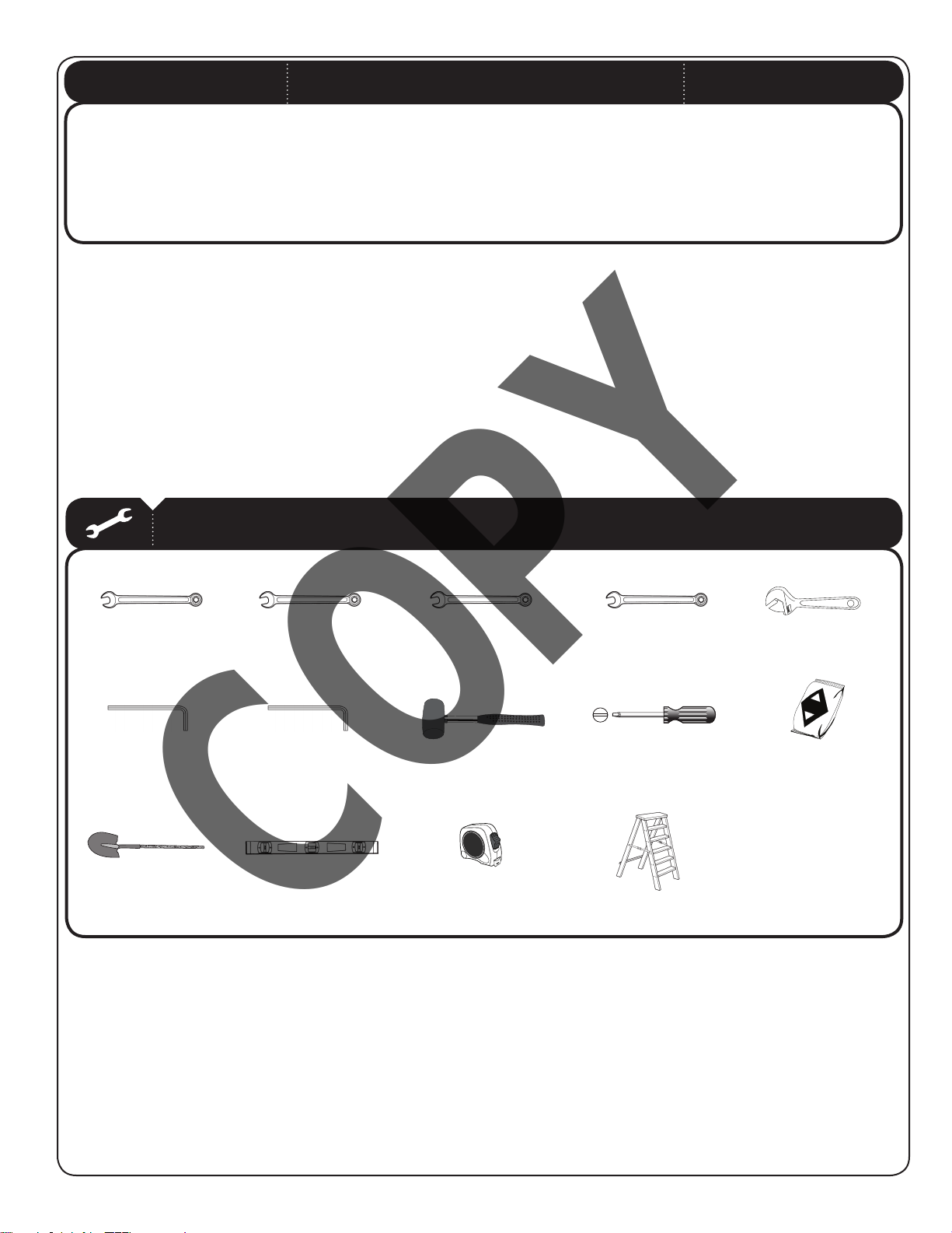
TOOLS AND PARTS REQUIRED FOR THIS ASSEMBLY
1/2”
(2)
1/4” Allen Wrench
(1)
Shovel Carpenter’s Level
(1) (1)
3/8” Allen Wrench
3/4”
(1)
(1)
9/16”
(2)
Rubber Mallet
(1)
Tape Measure
(1)
15/16”
(2)
Flathead Screwdriver
(1)
Ladder
(2+)
Adjustable Wrench
(1, optional)
Cement
(1,680 lb / 762 kg)
4
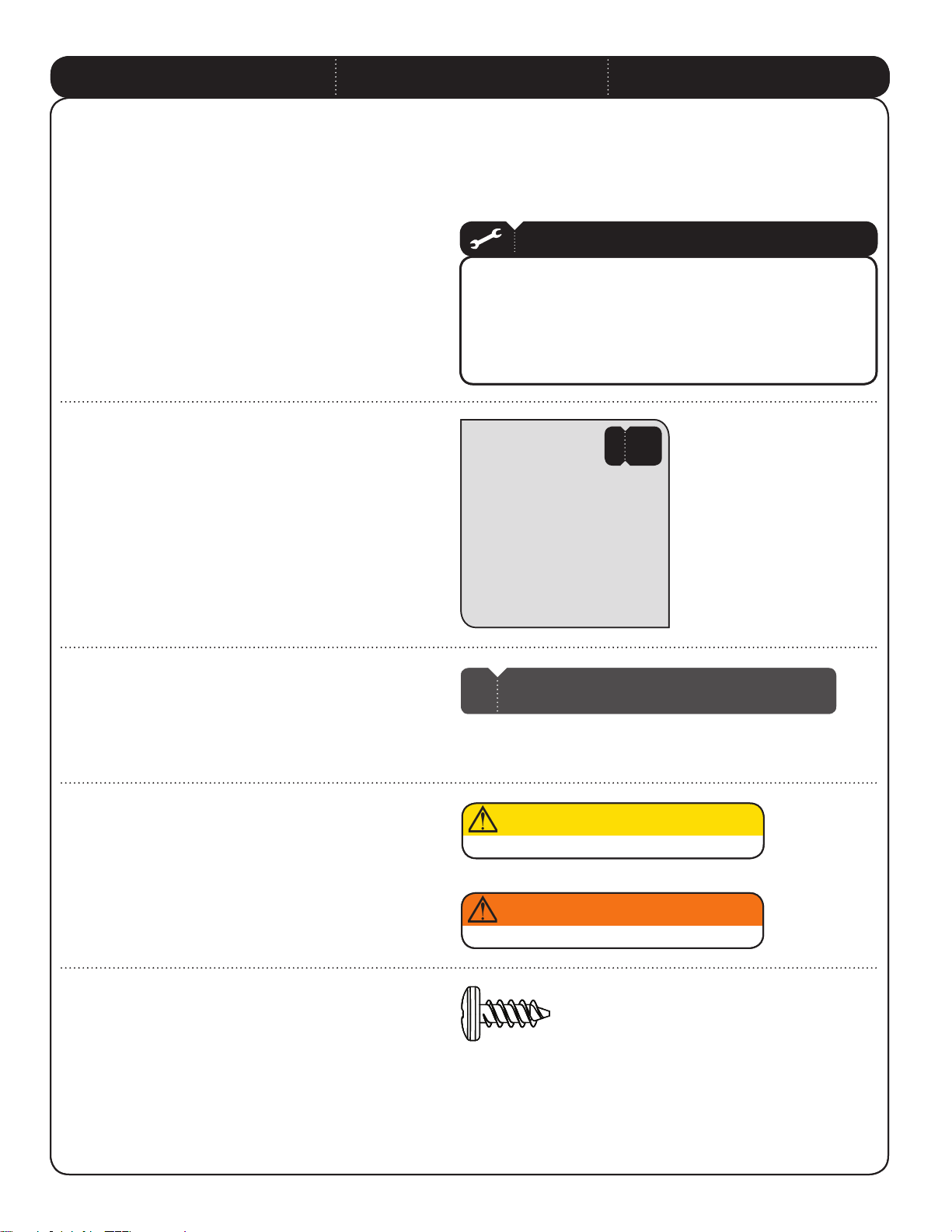
ASSEMBLY GUIDES
ASSEMBLY GUIDES
Refer to the following areas throughout the instructions
Refer to the following areas throughout the instructions
to assist in the assembly process:
to assist in the assembly process:
This area is located at the top, left-hand
This area is located at the top, left-hand
corner of the page and indicates which tools
corner of the page and indicates which tools
and hardware are needed to complete the
and hardware are needed to complete the
assembly steps on a page.
assembly steps on a page.
This area is located at the top, right-hand
This area is located at the top, right-hand
corner of the page and shows an image of the
corner of the page and shows an image of the
product with shaded parts indicating which
product with shaded parts indicating which
section is being assembled.
section is being assembled.
TOOLS AND HARDWARE REQUIRED FOR THIS PAGE
TOOLS AND HARDWARE REQUIRED FOR THIS PAGE
#
#
SEC
SEC
This area is usually located in the bottom,
This area is usually located in the bottom,
left-hand corner of a step and indicates that
left-hand corner of a step and indicates that
special attention is needed to perform a
special attention is needed to perform a
particular part of a step.
particular part of a step.
These areas are usually located in the bottom,
These areas are usually located in the bottom,
right-hand corner of a step and indicate that
right-hand corner of a step and indicate that
damage to the product or serious injury may
damage to the product or serious injury may
occur if the caution or warning is not heeded.
occur if the caution or warning is not heeded.
Throughout the Parts & Hardware List, Part
Throughout the Parts & Hardware List, Part
& Hardware Identifi ers, and instructions
& Hardware Identifi ers, and instructions
are three-letter IDs. These IDs are below
are three-letter IDs. These IDs are below
the images of the parts and hardware to
the images of the parts and hardware to
help you locate and identify the parts and
help you locate and identify the parts and
hardware during assembly. These IDs are not
hardware during assembly. These IDs are not
necessarily on the parts themselves.
necessarily on the parts themselves.
Note:
Note:
!
!
CAUTION
CAUTION
WARNING
WARNING
ADZ (x10)
ADZ (x10)
1/4” x 5/8” Pan-Head Screw
1/4” x 5/8” Pan-Head Screw
ID Item Description Qty
CZA Parts Box 1
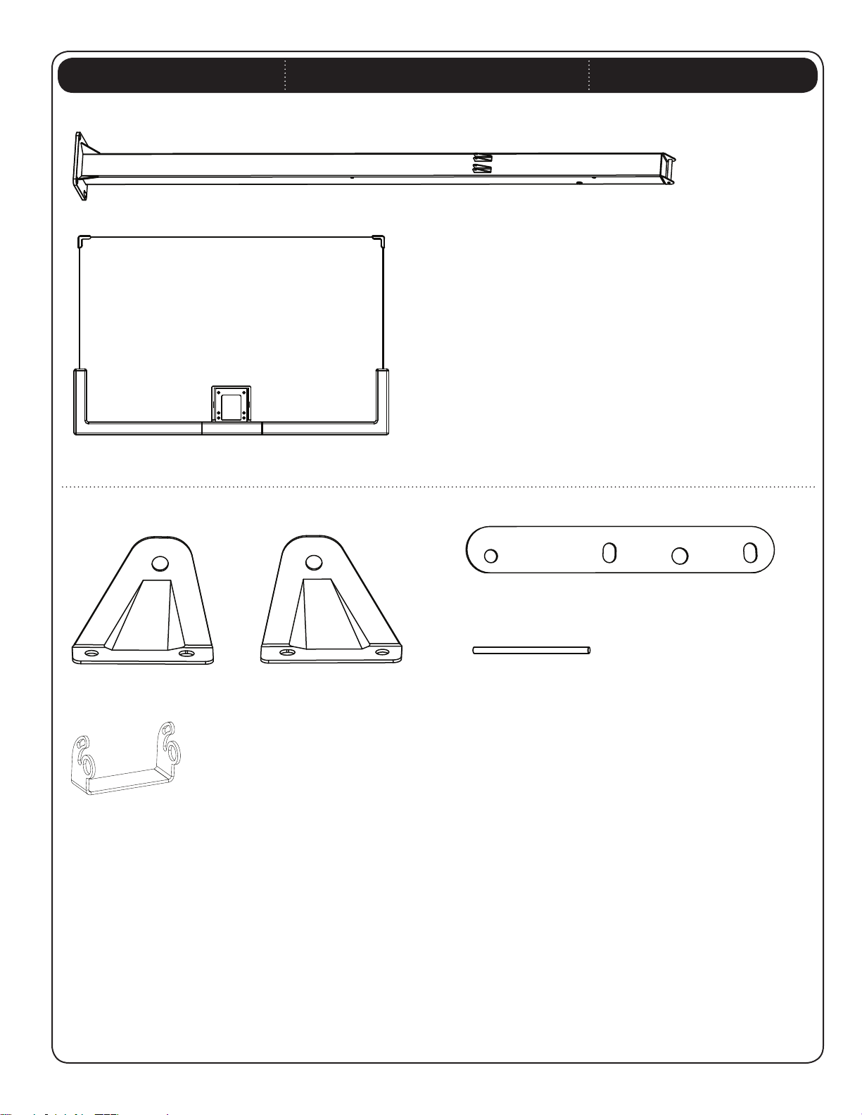
ALG Pole 1
AKD Upper Extension Arm 2
AKE Lower Extension Arm Assembly 1
AJR Gas Spring 2
AKG Gas Spring Cover 2
ALS Lifter Arm 2
AEZ 36” Rebar 4
AEI J-Bolt 4
AKT J-Bolt Template 1
CXY Left Cam Plate 1
CXZ Right Cam Plate 1
AMT Warning Sticker (Applied to Pole) 1
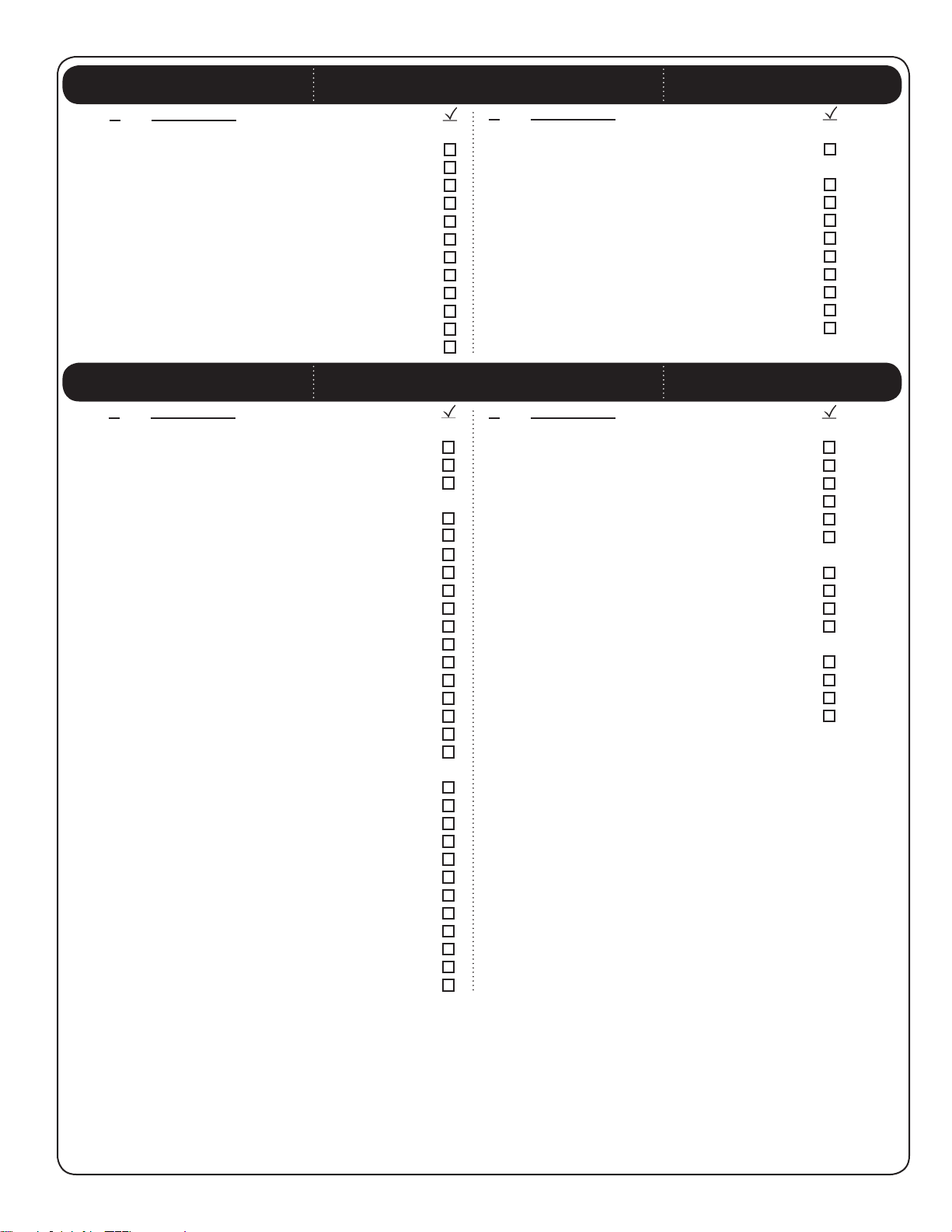
HARDWARE LIST
ID Item Description Qty
CZD Setup Hardware
AEO 5/8” x 2” Hex Bolt 1
CYV 5/8” Hex Nut Coupler 1
AER 5/8” Hex Nut 8
CZE Handle to Pole Assembly Hardware
CYL 5/16” x 5” Grade 2 Bolt 1
EKW .5” x 8.75” Bolt 3
EKV .625” x 8.875” Bolt 1
CYC 5/8” Large Poly Spacer 2
EKO 1/2” x 1 5/8” Spacer 4
CYQ 5/8” x 1” Spacer 1
EKN 5/8” x .9” Small Spacer 4
AAX 1/2” Centerlock Nut 3
CYN 5/16” Nylock Nut 1
EIP 5/8” Centerlock Nut 1
AEG 1/2” Plastic Washer 2
AEH 5/8” Plastic Washer 2
AJZ Dark Lithium Grease (not pictured) 1
AKH Silicone Grease (White) (not pictured) 1
CZF Extension Arms to Pole Assembly Hardware
CYI 5/8” x 11 1/4” Grade 5 Bolt 2
CYJ 5/8” x 8 1/4” Grade 5 Bolt 1
CYU 1/2” x 3 3/4” Grade 2 Bolt 4
DEF 1/2” x 9” Grade 8 Bolt 1
CYO 5/8” x 4 3/4” Spacer 1
CYQ 5/8” x 1” Spacer 2
CYP 5/8” x 2.9” Rubber Spacer 2
AEG 1/2” Plastic Washer 4
AEH 5/8” Plastic Washer 4
CYM 1/2” x 7/8” Washer 4
CYF 1/2” Grade 2 Nylock Nut 5
CYG 5/8” Grade 2 Nylock Nut 3
PARTS LIST
ID Item Description Qty
CZB Parts Box 2
AJI Backboard 1
CZC Parts Box 3
ALX Rim 1
AKZ Net 1
AKI Lift Handle 1
AMA Rim Cover Plate 1
CYA Handle Bracket 2
AMO Trigger Pin 1
AKX Handle Lock Bracket 1
ALC Pad Lock with Key (not pictured) 1
AKP Height Sticker 1
ID Item Description Qty
BCR Backboard to Pole Assembly Hardware
CYJ 5/8” x 8 1/4” Grade 5 Bolt 1
CYT 1/2” x 1 1/4” Grade 2 Bolt 2
AEH 5/8” Plastic Washer 2
AEG 1/2” Plastic Washer 6
CYG 5/8” Grade 2 Nylock Nut 1
CYF 1/2” Grade 2 Nylock Nut 2
CZG Pole to J-Bolt Template Assembly Hardware
ADL 5/8” Nylock Nut 4
AMS 5/8” Nylon Cap 4
BIP 5/8” USS Washer 8
CUA 5/8” Lock Washer 4
BCS Rim to Backboard Assembly Hardware
ABY 3/8” x 1 3/4” Hex Bolt 4
ADU M8 x 0.8 Panhead Screw 2
AAF 3/8” Flat Washer 8
AAA 3/8” Nylock Nut 4
6

Parts shown at 10% of Actual Size
AKE (x1)
Lower Extension Arm Assembly
AKD (x2)
Upper Extension Arm
PARTS IDENTIFIER
AKZ (x1)
Net
AJR (x2)
Gas Spring
AKG (x2)
Gas Spring Cover
AEZ (x4)
36” Rebar
ALS (x2)
Lifter Arm
AEI (x4)
J-Bolt
ALX (x1)
Rim Assembly
AMA (x1)
Rim Cover Plate
AKI (x1)
Lift Handle
AKP (x1)
Height Sticker
AKT (x1)
J-Bolt Template
7
Parts shown at 5% of Actual Size
ALG (x1)
Pole
AJI (x1)
Backboard
PARTS IDENTIFIER
Part shown at 25% of Actual Size
CXY (x1)
Left Cam Plate
AKX (x1)
Handle Lock Bracket
CXZ (x1)
Right Cam Plate
CYA (x2)
Handle Bracket
AMO (x1)
Trigger Pin
8
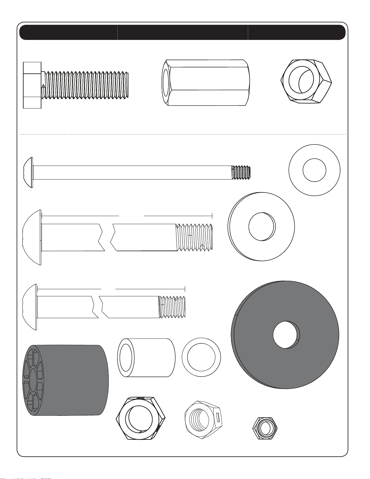
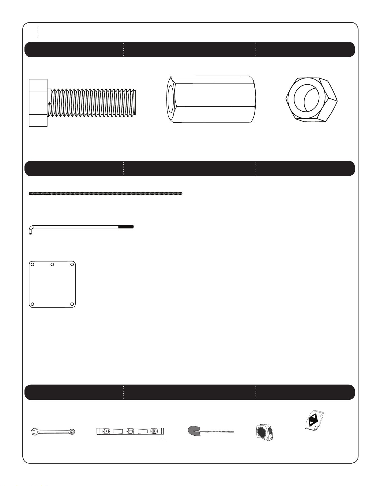
SETUP HARDWARE [CZD]
Hardware shown at Actual Size
HARDWARE IDENTIFIER
AEO (x1)
5/8” x 2” Hex Bolt
HANDLE TO POLE ASSEMBLY HARDWARE [CZE]
Hardware shown at Actual Size
CYL (x1)
5/16” x 5” Grade 2 Bolt
8.875”
EKV (x1)
.625” x 8.875”Bolt
(Not actual length)
CYV (x1)
5/8” Hex Nut Coupler
AER (x8)
5/8” Hex Nut
AEG (x2)
1/2” Plastic Washer
AEH (x2)
5/8” Plastic Washer
EKW (x3)
.5” x 8.75”Bolt
EKO (x4)
1/2” x 1 5/8” Spacer
8.75”
(Not actual length)
CYQ (x1)
5/8” x 1” Spacer
EIP (x1)
5/8” Centerlock Nut
EKN (x4)
5/8” x .9” Spacer
AAX (x3)
1/2” Centerlock Nut
9
CYC (x2)
5/8” Large Poly Spacer
CYN (x1)
5/16” Nylock Nut
HARDWARE IDENTIFIER
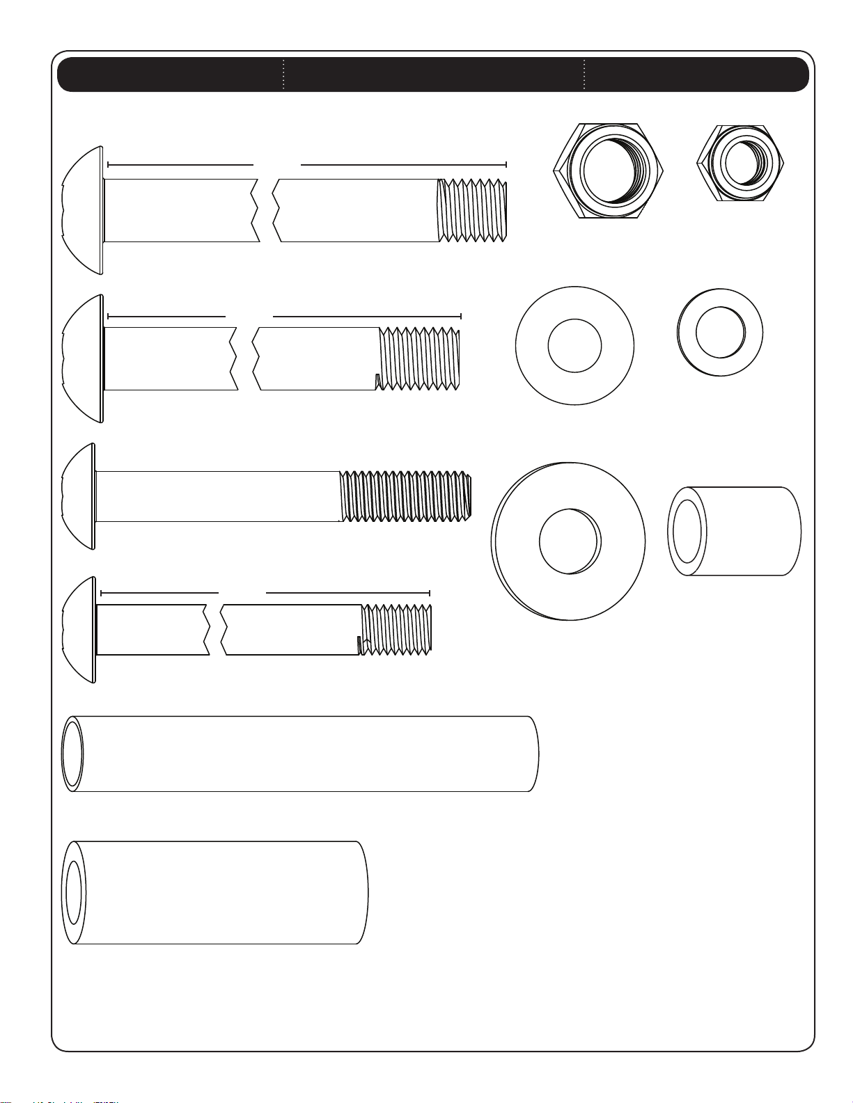
EXTENSION ARMS TO POLE ASSEMBLY HARDWARE [CZF]
Hardware shown at Actual Size
11 1/4”
CYI (x2)
5/8” x 11 1/4” Grade 5 Bolt
(Not actual length)
8 1/4”
CYG (x3)
5/8” Grade 2
Nylock Nut
CYF (x5)
1/2” Grade 2
Nylock Nut
CYJ (x1)
5/8” x 8 1/4” Grade 5 Bolt
CYU (x4)
1/2” x 3 3/4” Grade 2 Bolt
DEF (x1)
1/2” x 9” Grade 8 Bolt
(Not actual length)
(Not actual length)
9”
CYM (x4)
1/2” x 7/8” Washer
AEG (x4)
1/2” Plastic Washer
CYQ (x2)
5/8” x 1” Spacer
AEH (x4)
5/8” Plastic Washer
CYO (x1)
5/8” x 4 3/4” Spacer
CYP (x2)
5/8” x 2.9” Rubber Spacer
10
HARDWARE IDENTIFIER
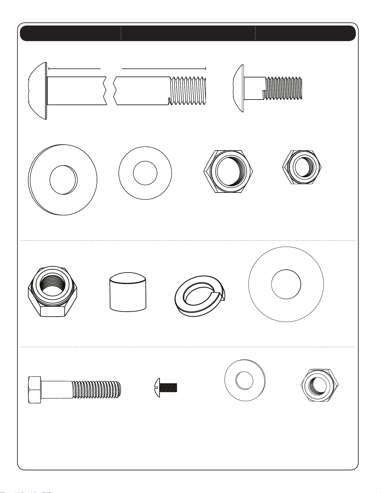
BACKBOARD TO POLE ASSEMBLY HARDWARE [BCR]
Hardware shown at Actual Size
8 1/4”
(Not actual length)
CYJ (x1)
5/8”-11 x 8 1/4” Grade 5 Bolt
AEG (x6)
1/2” Plastic Washer
AEH (x2)
5/8” Plastic Washer
CYT (x2)
1/2” x 1 1/4” Grade 2 Bolt
CYG (x1)
5/8”-11 Grade 2 Nylock Nut
CYF (x2)
1/2”-13 Grade 2 Nylock Nut
POLE TO J-BOLT ASSEMBLY HARDWARE [CZG]
Hardware shown at Actual Size
ADL (x4)
5/8” Nylock Nut
AMS (x4)
5/8” Nylon Cap
RIM TO BACKBOARD ASSEMBLY HARDWARE [BCS]
Hardware shown at Actual Size
ABY (x4)
3/8” x 1 3/4” Hex Bolt
CUA (x4)
5/8” Lock Washer
ADU (x2)
M8 x 0.8mm
Panhead Screw
AAF (x8)
3/8” Flat Washer
BIP (x8)
5/8” Flat Washer
AAA (x4)
3/8”-16 Nylock Nut
11
SETUP
1
SEC
SETUP HARDWARE [CZD]
Hardware shown at Actual Size
HARDWARE REQUIRED
AEO (x1)
5/8” x 2” Hex Bolt
Parts shown at 10% of Actual Size
AEZ (x4)
36” Rebar
AEI (x4)
J-Bolt
CYV (x1)
5/8” Hex Nut Coupler
PARTS REQUIRED
AER (x8)
5/8” Hex Nut
AKT (x1)
J-Bolt Template
15/16" Wrench
(x2)
TOOLS USED (NOT INCLUDED)
Carpenter’s Level Shovel
12
Tape Measure
Cement
(1,680 lb / 762 kg)
15/16” (x2)
TOOLS AND HARDWARE REQUIRED FOR THIS PAGE
(not actual size)
1
SEC
SEC
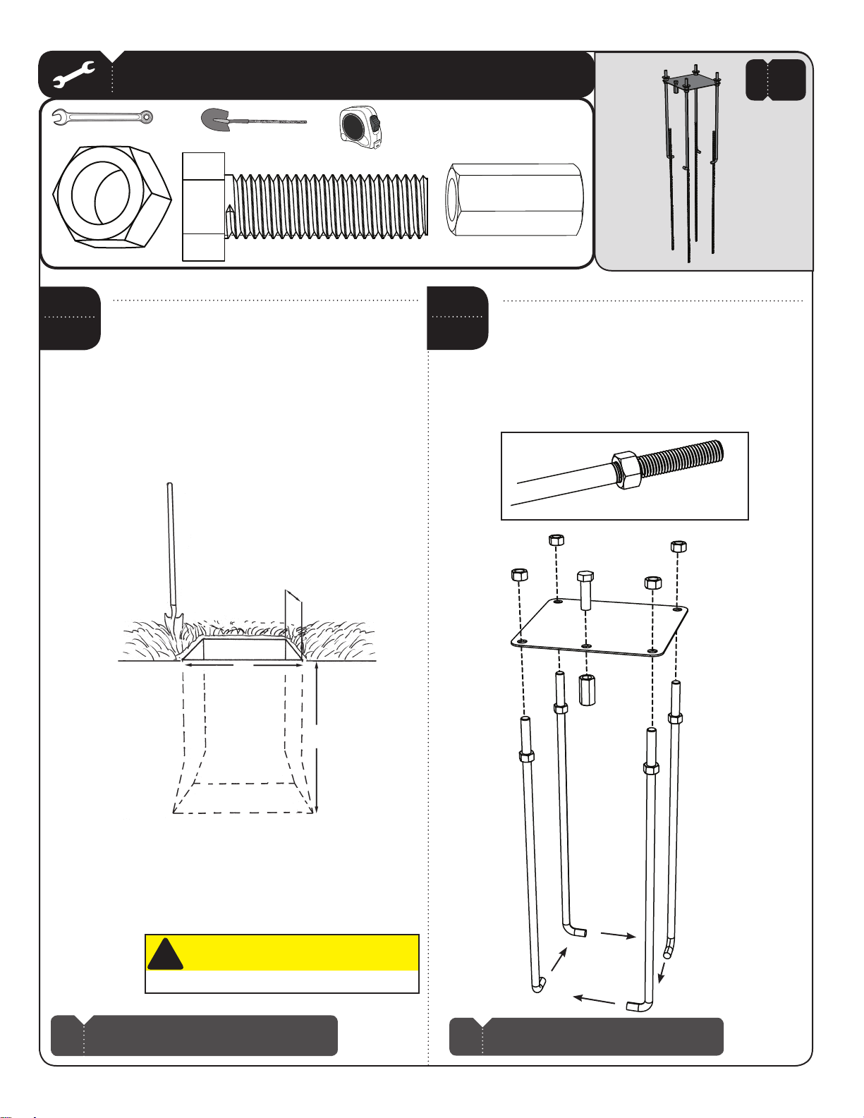
1.1
AER (x8)
Dig a hole 48” deep and 21” square. The edge of
the hole should be flush with the edge of the playing
court. If you live in an area where frost heaves
may pose a problem, consult your local building
inspector to determine the appropriate hole depth.
Bell out the bottom of the hole as illustrated. We
recommend building a form to keep the top of the
concrete straight and square. Place the form so it
is level with the playing surface.
AEO (x1)
21”
CYV (x1)
SEC
1.2
Thread a 5/8” Hex Nut (AER) all the way onto each
J-Bolt (AEI). Slide the threaded ends of the J-Bolts
through the corner holes in the J-Bolt Template (AKT)
and secure them completely with 5/8” Hex Nuts (AER).
Insert the 5/8” x 2” Hex Bolt (AEO) through the center
hole in the J-Bolt Template and tighten the Nut
Coupler (CYV) onto the Bolt as far as it will go.
AER
AEI
AER
AEO
AKT
21”
!
Before digging, call to locate any buried utility lines.
Note: There must be a 3-foot area behind the pole
!
to allow the user to adjust the Rim height.
CAUTION
48”
CYV
AER
AEI
Note: Make sure the curved ends of the J-Bolts
!
are in a rectangular pattern as shown.
13
TOOLS AND HARDWARE REQUIRED FOR THIS PAGE
(1,680 lb / 762 kg)
(Not to scale)
NO HARDWARE REQUIRED FOR THIS PAGE
1
SEC
SEC
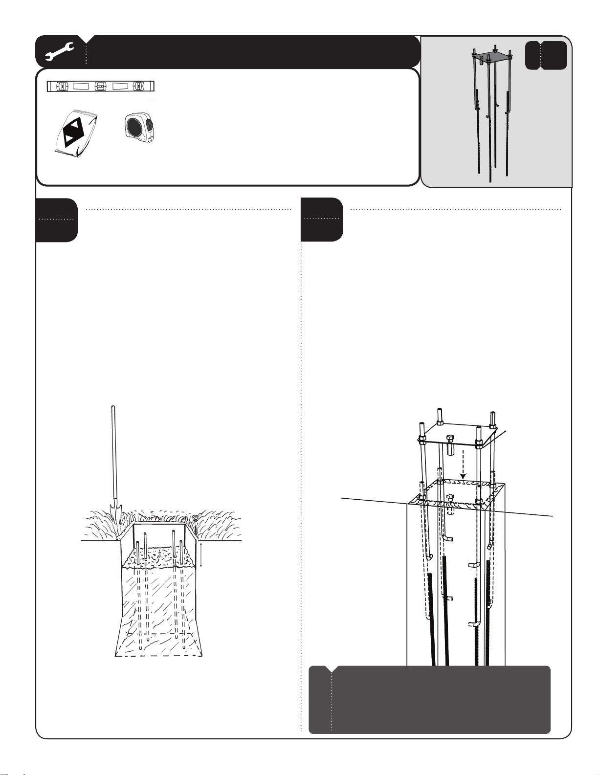
1.3
If you are using concrete mix, mix the concrete
according to the instructions on the bags. Please
note that a thicker mix of concrete will dry stronger.
Pour the concrete into the hole, stopping about 18
inches from the top of the hole.
Push the four pieces of 36” Rebar (AEZ) firmly to the
bottom of the hole. The Rebar should be arranged
in a square about 8 inches wide in the center of
the hole so each piece will be next to the J-Bolts
when they are placed in the cement.
Finish filling the hole to the top with concrete. The
top of the concrete should reach about 1/2” above
the playing surface and slope down toward the
playing surface to allow water runoff.
SEC
1.4
Center the J-Bolt Template (AKT) over the hole. The front
of the Template is the side with the Nut Coupler (CYV) and
should be toward the playing surface.
Insert the J-Bolts (AEI) into the concrete and agitate the
Template assembly to eliminate any air bubbles.
Push the J-Bolts into the cement until the Template
is resting flat against the cement. Form the cement
into a downward slope toward the playing surface
to allow water runoff. The lower four 5/8” Hex Nuts (AER)
and the Nut Coupler will be in the concrete permanently.
Clean off any concrete on the J-Bolt Template or the
exposed portion of the J-Bolts. Using a carpenter’s
level, make sure the Template is square to the playing
surface. Plate should be level and about 1/2” above
the playing surface for water to drain off of the steel.
AKT
CYV
AER
AEZ
18”
14
AEI
Playing surface
Note: You are now finished with the initial assembly steps. DO
!
NOT PROCEED WITH THE ASSEMBLY until the concrete has fully
cured. Curing will take a minimum of 72 hours (3 days). In
humid climates or wet weather, allow additional time for the
concrete to cure. Never use the system without first following
the cementing instructions.
 Loading...