


®
VISIT THE LIFETIME WEB SITE:
WWW.LIFETIME.COM
**U.S. and Canada customers ONLY**
IF ASSISTANCE IS NEEDED,
DO NOT CONTACT THE STORE!!!
CALL OUR CUSTOMER SERVICE DEPARTMENT at 1 (800) 225-3865
HOURS: 7:00 a.m. to 5:00 p.m. Monday through Friday, 7:00 a.m. to 4:00 p.m. Saturday (Mountain Standard Time)
**For customers outside the U.S. or Canada, please contact the store for assistance.**
9/5/2002
WORLD CLASS® ACTION GRIP
MODEL #71793
WARNING
Failure to comply with any of the warnings
in these instructions may result in serious
personal injuries such as cuts, broken
bones, nerve damage, paralysis, brain
injury, or death. Failure to comply may
also result in property damage. Please
heed all warnings and cautions. To ensure
your safety, do not attempt to assemble
this system without reading and following
all instructions carefully. Identify and
inventory the parts using the Parts List.
BASKETBALL SYSTEM
ASSEMBLY INSTRUCTIONS
AND OWNERS MANUAL
*A MINIMUM OF TWO ADULTS
ARE REQUIRED FOR
ASSEMBLY*
Save this instruction in the event that the manufacturer has to be contacted for replacement parts.
INSTRUCTION #FH05600 C
1

PARTS LIST
ID Part # Description Qty
TP 830081 Top Pole 1
MP 800707 Middle Pole 1
BP 830181 Bottom Pole 1
RB 850163 Left Backboard Bracket 1
LB 850162 Right Backboard Bracket 1
AZ ZJ04299 Backboard 1
AA 500096 Pole Cap 1
AB 502005 Net 1
AD 504068 Counterbalance Spring 2
F028011 Warning Sticker (Applied) 1
AI F028010 Height Sticker 1
AJ 825601 Rim 1
AK 830204 Short Extension Arm 2
AL 830205 Long Extension Arm 2
AE 700506 Wood Block 1
AF AM01500 Rim Support Bracket 1
Main Hardware (HH01700C)
HA 300022 1/4" Centerlock Nut 2
HB 300029 1/2" x 7 1/8" Hex Bolt 5
HC 300110 1/4" x 2 3/4" Hex Bolt 2
HD 301008 1/2" Centerlock Nut 5
HE 302005 3/8" x 7" Hex Bolt 1
HF 302008 3/8" Centerlock Nut 1
HI 500013 9/16" x .592 Poly Spacer 4
HJ 500032 1/2" x 1/8 Spacer 4
HK 500037 1/2 x 1" Poly Spacer 2
HL 800324 1/2" x 2 5/16" Metal Spacer 2
HM BS00800 5/16 x 1 Screw 2
Rim Hardware (HH01900B)
RA 300066 5/16" Hex T-Nut 2
RK 300128 5/16" Jam Nut 2
RC 302014 5/16" Flat Washer 2
RD 302056 Rubber Washer 2
RE 302067 5/16" x 2 3/4" Tap Bolt 2
RF 302081 5 1/2 U-Bolt 1
RG 302090 5/16" Nylock Flange Nut 4
RJ 502060 Compression Spring 2
RI 804033 Spring Retainer Plate 1
HA
RA
RI
HARDWARE IS ACTUAL SIZE
(unless otherwise indicated)
HDHC
HJ
RC
RK
RE
HF HI
HK
RD
RG
HL
2
HE
HB
HM
(not actual size)

PARTS LIST
!
!
ID Part # Description Qty
AN A040031 Inner Channel 1
AO Z097015 Outer Tube 1
AP C050018 Channel Stop 1
AQ Z097017 Pole Bracket 1
AR C050019 Handle 1
AS C050017 Trigger 1
Action Grip™ Hardware (HH01300)
GA A070044 Lock Tab 1
GB B070040 1/4-20 x 1 1/2 Screw 2
GC B080015 Trigger Spring 1
GD BW00100 #6 Flat Washer 2
GE 300027 5/16 x 1 3/4 Hex Bolt 1
GF 300031 3/8 Flat Washer 2
GH 300095 5/16 Cap Nut 1
GI 300103 #6 x 3/8 Phillips Screw 2
HF 302008 3/8 Centerlock Nut 2
GK 302053 3/8 x 4 Hex Bolt 2
GL 800239 1/2 x 3 7/16 Spacer 2
Pole Joint Hardware (HD9139)
PA 300121 1/4" x 4" Carriage Bolt 2
PB 300127 1/4" Cap Nut 2
GA
(Not actual size)
GF
PA PB
HARDWARE IS ACTUAL SIZE
(unless otherwise indicated)
GB GD
GH GI GK
GC GE
(Not actual size)
GL
Tools and Materials Required For Assembly
(Not Included)
1. Adjustable Wrench
2. 7/16 Wrenches (2)
3. 1/2 Wrenches (2)
4. 9/16 Wrenches (2)
5. 3/4 Wrenches (2)
6. 3/8 Wrench
7. Hammer or Mallet
8. Tape Measure
9. Water Supply
10. Concrete mix
(six 90-lb. bags)
11. Phillips Screwdriver
12. Shovel
13. Marker
14. 3 Length of Rebar
15. Carpenters Level
STOP
A. Identify and inventory all parts using the Parts List. Keep the hardware
BEFORE BEGINNING ASSEMBLY
STOP
bags and their contents separate. If any parts are missing, call our Customer
Service Department.
B. Test fit all Bolts by inserting them into their respective holes. If necessary,
carefully scrape away any excess powder coating buildup from inside the
holes. Do not scrape away all of the powder coating. Bare metal may rust.
You may need to pound some Bolts into place with a hammer.
C. Purchase six 90-lb bags of concrete ready-mix and a 3' length of rebar.
Choose the location of your pole carefully! Avoid putting the pole near
overhead power or utility lines. When digging the footing, consider the location
of any underground utilities.
3
SAFETY INSTRUCTIONS
Failure to follow these safety instructions may result in serious injury or property damage and will void the warranty. The owner must ensure that all players
know and follow these rules for safe operation of the system. Proper and complete assembly, use and supervision is essential for proper operation and to reduce the
risk of accident or injury. A high probability of serious injury exists if this system is not installed, maintained, or operated properly.
If using a ladder during assembly, use extreme caution. Follow all warnings and cautions on the ladder carefully. Two people are required for assembly. Before
digging, contact the appropriate agency to locate underground power, gas and/or water lines. Do not install the system within 20 feet of overhead power lines. Seat
the pole sections properly. Failure to do so could allow the pole sections to separate during play and/or transport of the system. Climate, corrosion, or misuse could
result in system failure. If technical assistance is required, contact the manufacturer. Minimum operational height is 7 6 to the Rim.
Most injuries are caused by misuse and/or failure to follow instructions. Use caution when using the system.
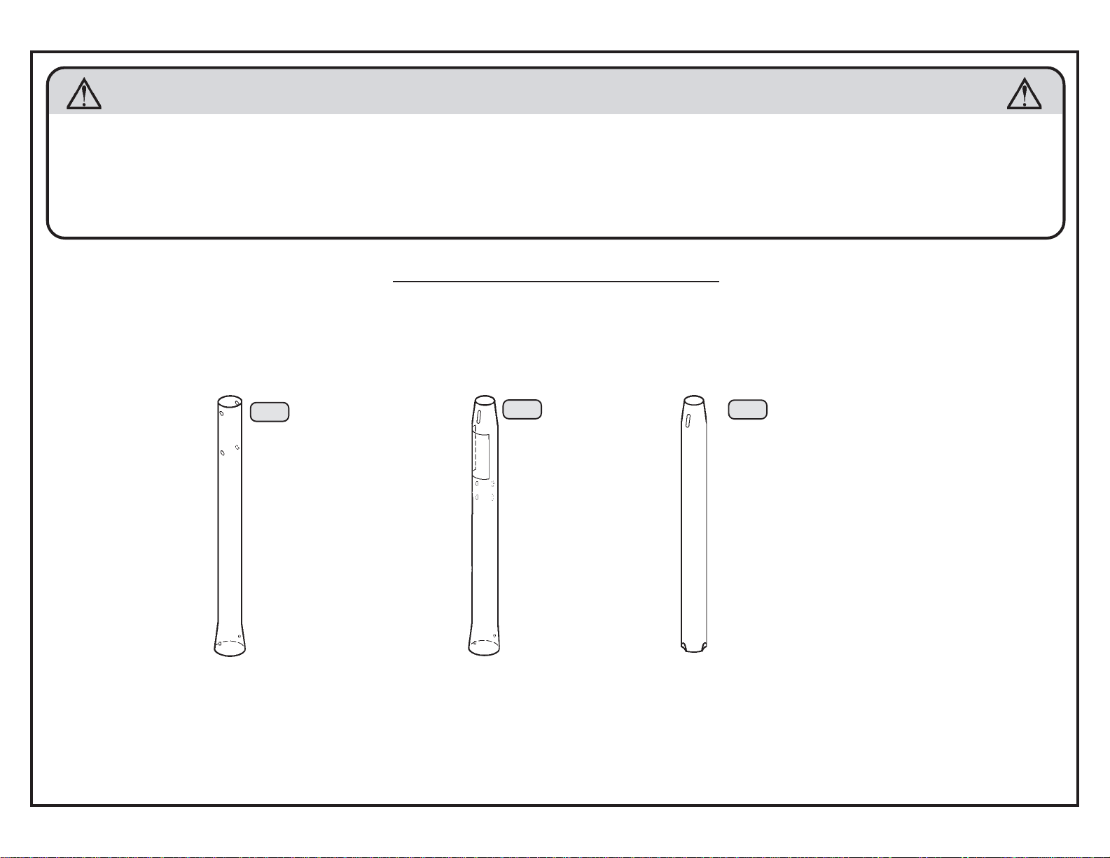
POLE SECTION IDENTIFICATION
Identify the pole sections before beginning assembly. Failure to assemble the pole sections correctly may result in severe
personal injury or property damage as described on Page One.
ONCE THE POLE SECTIONS HAVE BEEN SEATED, THEY CANNOT BE SEPARATED.
Note: Tapers and flares are exaggerated in the illustrations.
4
TP
Top Pole:
Four holes
at the top of
the pole and
two square
holes at the
bottom.
MP
Middle Pole:
Two slots at
the top of the
pole, four
holes in the
middle and
two square
holes at the
bottom.
Warning
Sticker.
BP
Bottom Pole:
Two slots at
the top of the
pole, dimples
at the bottom.

Required For
This Page:
9/16 Wrenches
HH01300
GK
(2)
HF
1
cementing the pole into the
ground permanently. See Page 11
Dig a round hole 24" deep and 18"
in diameter. The edge of the hole
should be flush with the edge of the
The Ground Sleeve
provides an alternative to
for more information.
playing surface.
(2)
18
2
Measure 14.5" up
from the dimpled
end of the Bottom
Pole (BP) and
make a mark (do
BP
not scratch the
powder coating).
3
Mix 5 1/2 bags of concrete. Save 1/2 bag
of concrete to use later in the assembly.
Fill the hole with concrete.
Insert the Bottom Pole up to the 14.5 mark
and 4 away from the playing surface.
4
Insert a 3/8 x 7 Hex
Bolt (HE) into the slots in
the pole and rotate the
pole so the Hex Bolt is
parallel to the playing
surface.
4"
HE
GF
(2)
GL
(2)
24
5
Check the pole several times within the first
hour to make sure that all sides are vertical
concrete. The 14.5 mark must remain level
Form the cement so it slopes away
from the pole to allow water runoff.
Failure to do so may result in
premature rusting of the pole.
Place the 1/2" x 3' rebar (not included)
inside the Bottom Pole (BP).
and that the pole does not sink into the
with the playing surface.
Rebar
Allow 1-4 hours
for the concrete
to set.
14.5
A thicker mix of
concrete will dry
stronger.
6
Allow the concrete to set for at least 72 hours (3 days)
Do not continue until the concrete has set
for 1 to 4 hours.
Remove the Hex Bolt from the top of the pole.
Mix the remaining 1/2 bag of concrete and pour the
concrete into the Bottom Pole until it is just below the
slots in the top of the pole. Tamp the concrete down
with a broom handle to remove any air pockets.
Do not overfill the pole or you may not be
able to assemble the rest of the pole
sections.
Clean all excess concrete off the
outside surface of the pole.
before continuing with the assembly.
STOP!
The concrete must cure for at least 72 hours (3 days) before
installing the rest of the system. In humid climates or wet
weather, allow additional time for the concrete to cure. Do not
proceed until the curing process is complete.
Playing
Surface
7
HF
GK
GF
Small
holes
MP
Completely tighten the Nuts.
GL
Large
holes
AQ
5

Required For This Page:
7/16 Wrenches
1/2 Wrenches
HD9139
HH01900B
RA
PB
(2)
RC
(2)
PA
(2)
RD
(2)
RE
HH01700C
HL
(2)
(1)
(1)
(2)
HC
8
TP
MP
10
Do not jam the poles
together until instructed.
Make sure the square
portion of the Bolt is
completely inside the
square hole.
Square holes
PB
PB
Secure only finger
RB
PA
tight now.
PA
9A
Strike the pole on
the Wood Block
(AE) 5 to 6 times
on each end.
Do not hit your
feet with the
pole, as serious
injury could
Failure to seat the pole sections together
and secure the Carriage Bolts could
cause the pole sections to separate,
resulting in property damage or personal
injuries as listed on Page One.
11
Make sure the U-Bolt is in
TP
occur.
AE
WARNING
the notches.
MP
9B
the Middle Pole. It must measure
longer than 83 5/8, strike it again on
the wood. If it is still too long, do not
Completely tighten the Cap
Measure from the top of the
Top Pole to the bottom of
83 5/8 or less. If it measures
complete assembly. Call our
Customer Service Department.
Nut installed in Step 8.
WARNING
Do not overtighten the Cap Nut. If the
end of the Bolt breaks through the
plastic cap, call our Customer Service
Department at the number on Page
One. Exposed threads on the end of the
Bolt may cause serious injuries such as
those listed on Page One.
12
RC
RE
RD
6
TP
83 5/8
MP
RA
HA
(2)
LB
RF
RB
HC
LB
HA
HA
Completely tighten the Nuts (HA).
HL
The Tap Bolts (RE)
should be at the outer
HC
edge of the holes.
RD
Tighten the T-Nuts (RA) only until the
Rubber Washers (RD) begin to bulge.

Required For This Page:
1/2 Wrenches
3/8 Wrench
HH01900B
(2)
RK
RG
(4)
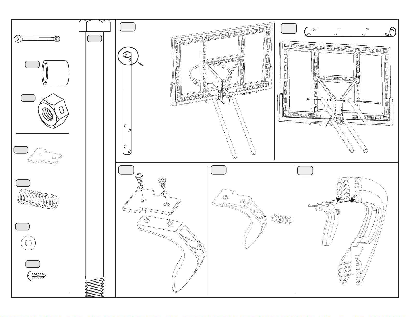
13
Lay the Backboard on a
bench or table.
The U-Bolt (RF) goes through the
top holes in the Backboard. The Rim
Support Bracket (AF) lines up with
the lower holes in the Backboard
Brackets and Backboard.
RK
RG
Only hand tighten
the Nuts (RG).
AF
Tighten the Jam Nuts (RK) onto
the U-Bolt as far as they will go.
14
RG
RI
RJ
Only hand tighten the
Nuts (RG) now.
Tightening these Nuts later will
adjust the Rim tension.
RI
(1)
(not
actual
size)
HH01700C
HM
(2)
15
Bend the Backboard Brackets (LB & RB) out.
LB
RB
Use a 3/8 wrench to attach the Screws (HM) through the top holes in
the Backboard Brackets and into the Backboard.
HM
Completely tighten all Rim hardware.
HM
7
8
Required For This Page:
3/4 Wrenches
Screwdriver
HH01700C
HI
(4)
HD
(2)
HH01300
GA
(1)
(Not actual size)
GC
(1)
HB
(2)
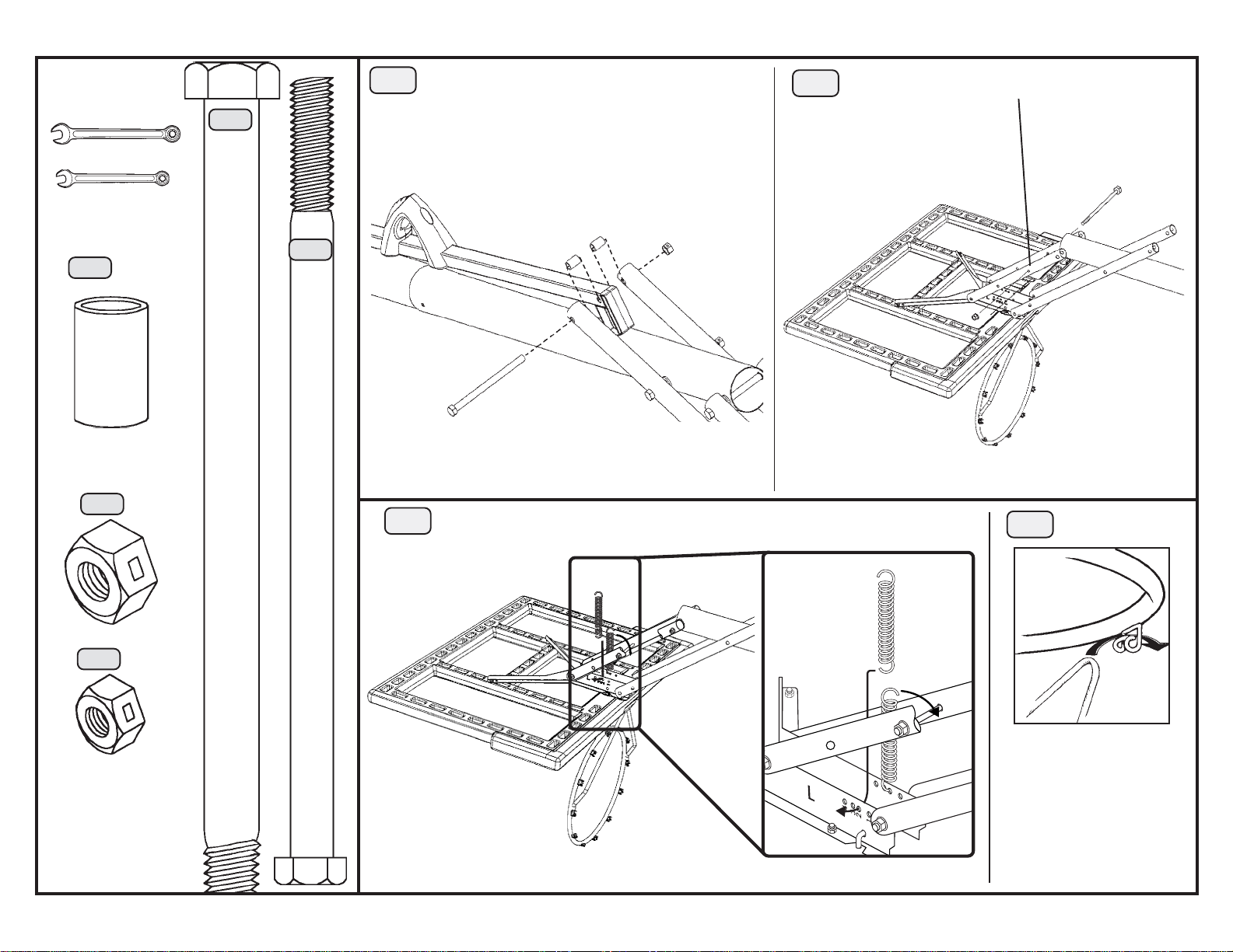
16
Attach this end
Arms (AL) to
the Backboard
18
GI
GD
of the Long
Extension
Brackets
Tighten until the Nut is
flush with the Bolt.
GI
GD
HD
AL
19
HI
HB
AL
17
HI
HD
AK
Tighten the Nut until it is flush with the Bolt.
AK
HB
HI
AK
20
AR
(Not actual size)
(2)
GD
(2)
GI
AS
GA
AS
AS
GC

Required For
This Page:
3/4 Wrenches
1/2 Wrenches
Screwdriver
HH01300
GB (2)
HB
(2)
21
AO
Remove the Inner
Channel that is packaged
inside the Outer Tube
(AO) before attaching the
Handle (AR).
AR
22
**2 Adults Required For
This Step**
The Backboard and Rim
should be on the ground
resting on cardboard with the
Extension Arms facing up.
AK
HB
HB
23
AN
AI
GEGH(1)
(1)
HH01700C
HD
(2)
GB
GB
24
AN
AN
AK
HD
AR
The Backboard must be on the opposite side
of the pole as the Pole Bracket.
Squeeze the Trigger while inserting the
Inner Channel into the Outer Tube.
Insert the slotted end first.
AO
HD
HJ
AO
25
AO
AL
AP
AL
26
AI
GE
AN
The bottom of the Sticker (AI)
lines up with the bottom edge
of the Inner Channel (AN).
Tighten the Nut securely.
GH
HJ
(4)
AN
AO
Slide the Outer Tube
(AO) up to the 10 mark
and release the Trigger
so it clicks into place.
WARNING
Do not overtighten the Cap Nut. If the end of
the Bolt breaks through the plastic cap, call our
Customer Service Department at the number
on Page One. Exposed threads on the end of
the Bolt may cause serious injuries such as
those listed on Page One.
9
10
Required For
This Page:
3/4 Wrenches
9/16 Wrenches
HH01700C
(2)
HK
(1)
HD
HB
(1)
HE
(1)
27
29
**2 People Required For
This Step**
HK
AO
HB
Completely tighten the Nut.
HK
AL
Hook the Springs (AD) into the #2 holes in the Backboard Brackets.
HD
AL
28
Remove the plastic film
from the Backboard.
Use the holes closest to the pole.
Tighten all Nuts securely now.
HF
30
HE
Attach the Net.
HF (1)
Use the closed end
of a wrench to pull
the Springs up and
over the Bolt.
AD
Please call our Customer
Service Department at
the number on Page One
to obtain replacement
Nets. Our Nets are
shorter than average to
reduce the risk of
entanglement.
Required For
This Page:
7/16 Wrench
Hammer/Mallet
HD9139
(1)
PB
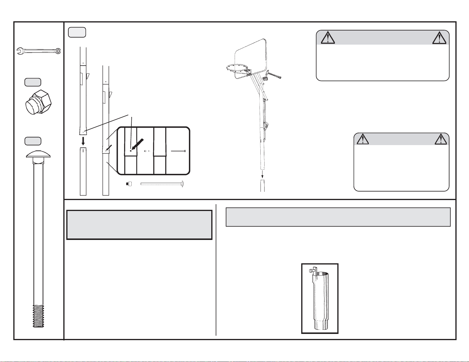
31
MP
**2 People Required For This Step**
With the Backboard facing the playing
surface, line up the holes in the Middle Pole
with the slots in the Bottom Pole. Carefully lift
the system onto the Bottom Pole.
Make sure the square portion of the Bolt
is completely inside the square hole.
Square holes
Completely
tighten the Cap
Nuts (PB) now.
WARNING
Failure to seat the pole sections together and secure
the Carriage Bolts could cause the pole sections to
separate, resulting in severe personal injuries such as
broken bones, cuts, nerve, spinal cord or brain injury,
or death. Property damage may also occur.
AE
Place the Wood Block
(AE) on the Top Pole
and strike it firmly with a
hammer or mallet six or
seven times.
PA
(1)
BP
PB
PB
PA
PA
Operation of the height
adjustment system
The adjustable system may be adjusted from 7 1/2 feet
to 10 feet in 6-inch increments.
Hold the Handle tightly and squeeze the Trigger. Raise
the Handle to lower the Backboard, or lower the Handle
to raise the Backboard.
WARNING
Do not overtighten the Cap Nut. If the
Insert the Pole
Cap (AA) into the
top of the pole.
Accessories available for more basketball fun!
PRODUCT DESCRIPTION MODEL #
Universal Ground Sleeve 0023
Universal Ground
Sleeve #0023
The Universal Ground Sleeve
enables the pole to be cemented
in, yet still removable. The
sleeve sits flush with the ground
after installation. Fits 3.5"
diameter poles.
end of the Bolt breaks through the
plastic cap, call our Customer Service
Department at the number on Page
One. Exposed threads on the end of the
Bolt may cause serious injuries such
as those listed on Page One.
For price and freight information call
our Customer Service Department.
To place orders, use a Master
Card or Visa and call our Customer Service Department:
LIFETIME PRODUCTS, INC.
P.O. BOX 160010
BLDG. D-11, FREEPORT
CENTER
CLEARFIELD, UT 84016-0010
1-800-225-3865
11

12
ADJUSTING
SYSTEM HEIGHT
Lower
Raise
TO RAISE:
pull trigger, then slide the handle
down. (SEE ILLUSTRATION)
TO LOWER:
pull trigger, then slide the handle
up. (SEE ILLUSTRATION)
Grip handle and
Grip handle and
CAUTION
WATCH FOR
PINCH
POINTS
CUSTOMER SERVICE
(USA/CANADA ONLY)
1-800-225-3865
#F028011
WARNING
• Failure to comply with these warnings could
result in broken bones, cuts, nerve damage,
spinal cord or brain injury, or death.
• Keep hands away from all moving parts while
raising or lowering the rim.
• DO NOT HANG FROM ANY P ART OF THE UNIT,
including the backboard, support braces, rim,
or net.
• DO NOT allow children to adjust the unit.
• DO NOT slide, climb, or play on the pole.
• Keep organic material away from the pole
base. Grass, litter, etc. could cause corrosion
and/or deterioration.
• Check pole system twice a year for signs of
corrosion (rust, pitting, chipping) and repaint
with exterior enamel paint. If rust has
penetrated through the pole or any component,
replace damaged parts immediately.
• Check the unit before each use for stability.
• Inspect unit before each use for loose hardware, excessive wear and signs of corrosion.
Repair before use.
• Use caution when performing dunk-type
activities on this unit.
• All players must wear a mouth guard while
playing close to the net. During play, use
extreme caution to keep each player's face
away from the backboard, rim and net.
•Never play on damaged equipment.
• DO NOT wear jewelry (rings, watches,
necklaces, etc.) while using the system.
Serious personal injury may occur if jewelry is
caught on rim or net.
OWNERS MUST ENSURE THAT ALL PLA YERS
KNOW AND FOLLOW THESE RULES FOR SAFE
OPERATION OF THIS UNIT.
POLE CARE AND SYSTEM MAINTENANCE
The life of your basketball system depends on many variables. The climate, exposure to corrosives such as
salt, pesticides, or herbicides, and excessive use or misuse can all contribute to pole failure, which may
cause property damage or personal injury.
Check your basketball system frequently for loose hardware, excessive wear, and signs of corrosion. For safety
reasons, and to prolong the life of your basketball system, you must take the following preventive measures.
a. Check all Nuts and Bolts. If any are loose, tighten them.
b. Check all parts for excessive wear and tear. If necessary, replace any parts that have been worn or damaged
through usage. Check the Pole Cap for cracks or tears that could let water into the pole. Contact our
Customer Service Department for replacement parts.
c. Inspect the Warning Sticker on the pole. If it is ripped, faded, or illegible, call our Customer Service
Department to request a replacement Sticker.
d. Check all pole sections for visible rust or chipped or cracked paint. If either are present, do the following:
1. Use an emery cloth to completely remove any rust or chipped paint.
2. Clean the area with a damp cloth and allow it to dry.
3. Apply two coats of a rust preventative, high gloss enamel paint to the area. Allow the paint to dry
between coats.
IF RUST HAS PENETRATED THROUGH THE POLE ANYWHERE, REPLACE IT
IMMEDIATELY!

Basketball Equipment
5-Year Limited Factory Warranty
Lifetime Products, Inc. reserves the right to make substitutions to warranty claims if parts are unavailable or obsolete.
1. Lifetime basketball systems are warranted to the original purchaser to be free from defects in material and workmanship for a period of five years from the date
of original retail purchase. The word "defects" is defined as imperfections that impair the use of the product. Defects resulting from misuse, abuse or negligence
will void this warranty. This warranty does not cover defects due to improper installation, alteration or accident. This warranty does not cover damage caused by
vandalism, rusting, "acts of nature" or any other event beyond the control of the manufacturer.
2. This warranty is nontransferable and is expressly limited to the repair or replacement of defective basketball equipment. If the equipment is defective within the
terms of this warranty, Lifetime Products, Inc. will repair or replace defective parts at no cost to the purchaser. Shipping charges to and from the factory are not
covered and are the responsibility of the purchaser. Labor charges and related expenses for removal, installation or replacement of the basketball system or its
components are not covered under this warranty.
3. This warranty does not cover scratching or scuffing of the product that may result from normal usage. In addition, defects resulting from intentional damage,
negligence, unreasonable use or hanging from the net or rim will void this warranty.
4. Liability for incidental or consequential damages is excluded to the extent permitted by law. While every attempt is made to embody the highest degree of safety
in all equipment, freedom from injury cannot be guaranteed. The user assumes all risk of injury resulting from the use of this product. All merchandise is sold on
this condition, and no representative of the company may waive or change this policy.
5. This product is not intended for institutional or commercial use; Lifetime Products, Inc. does not assume any liability for such use. Institutional or commercial use
will void the warranty.
6. This warranty is expressly in lieu of all other warranties, expressed or implied, including warranties of merchantability or fitness for use. Neither Lifetime
Products, Inc., nor any representative assumes any other liability in connection with this product.
ALL WARRANTY CLAIMS MUST BE ACCOMPANIED BY A SALES RECEIPT.
REPORT PRODUCT DEFECTS IN WRITING TO:
Lifetime Products, Inc., PO Box 160010, Bldg. D-11, Clearfield, UT 84016-0010 or call (800) 225-3865, M-F 8 a.m. to 5 p.m. MST.
Please include your dated sales receipt and photographs of damaged parts.
TO REGISTER YOUR PRODUCT, VISIT OUR WEBSITE AT
WWW.LIFETIME.COM
13

14
®
To register your product, visit our website at
www.lifetime.com
®2002 Lifetime Products
PO Box 160010
Freeport Center, Bldg. D-11
Clearfield, UT 84016-0010 USA
 Loading...