

Lifetime 71559 Owner's Manual
Copy
2
**U.S. and Canada customers ONLY**
IF ASSISTANCE IS NEEDED,
DO NOT CONTACT THE STORE!!!
CALL OUR CUSTOMER SERVICE DEPARTMENT at 1 (800) 225-3865
HOURS: 7:00 a.m. to 5:00 p.m. Monday through Friday (Mountain Standard Time)
**Call or visit our Web site for Saturday hours**
INSTRUCTION #1030948
The product you just purchased could be FREE!
Register your product at www.lifetime.com and receive three important
benets:
1. You automatically will be entered to win $200 in our monthly drawing!
2. In the unlikely event of a product recall or safety modication, we can
notify you immediately and directly.
3. You may choose to receive Preferred Customer Announcements and
promotions regarding new Lifetime products.
www.lifetime.com
Save this instruction in the event that the manufacturer has to be contacted for
replacement parts.
MODEL #71559
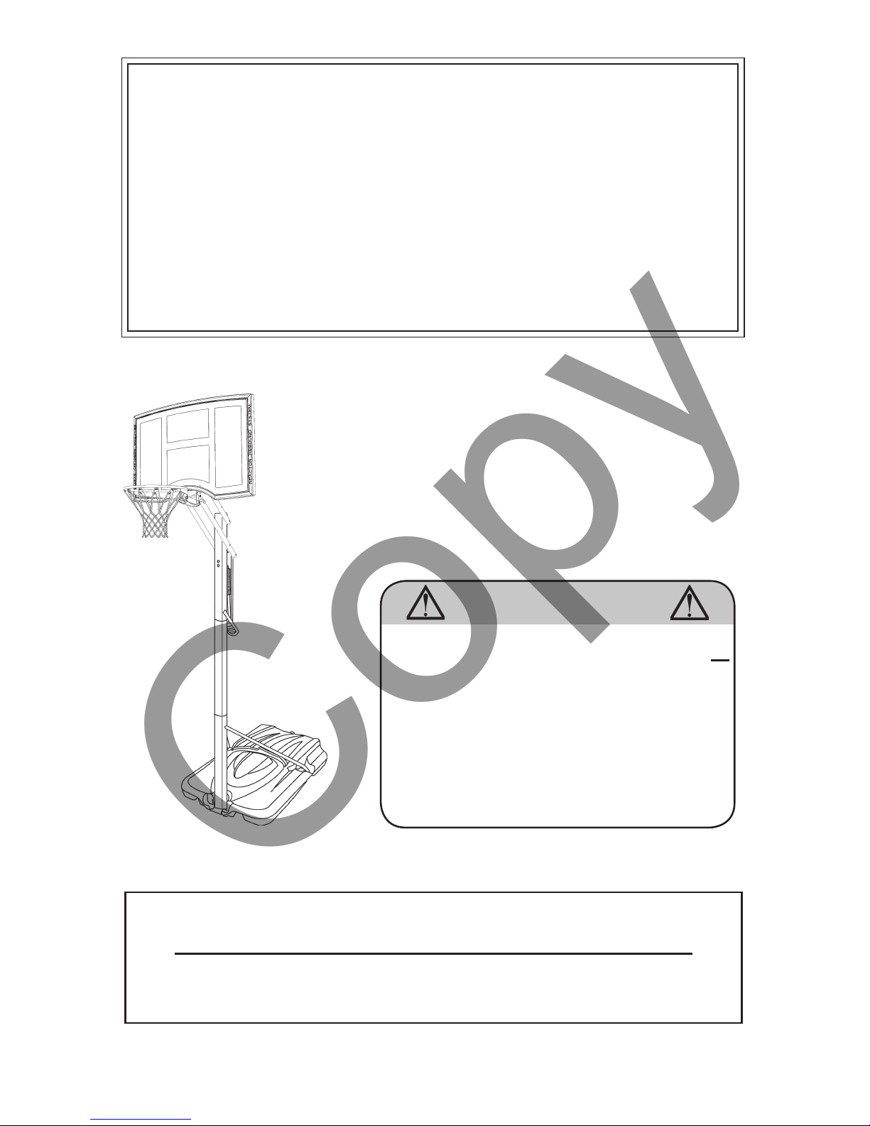
WARNING
To ensure your safety, do not attempt to assemble
this system without reading and following all
instructions carefully. Identify and inventory the
parts using the Parts List. Failure to comply with
any of the warnings in these instructions may
result in serious personal injuries such as cuts,
broken bones, nerve damage, paralysis, brain
injury, or death. Failure to comply may also result
in property damage. Please heed all warnings
and cautions.
POWER LIFT® XL
BASKETBALL SYSTEM
WITH POWER SHOCKTM RIM
09/17/2007
**For customers outside the U.S. or Canada, please contact the store for assistance.**
Copy
3
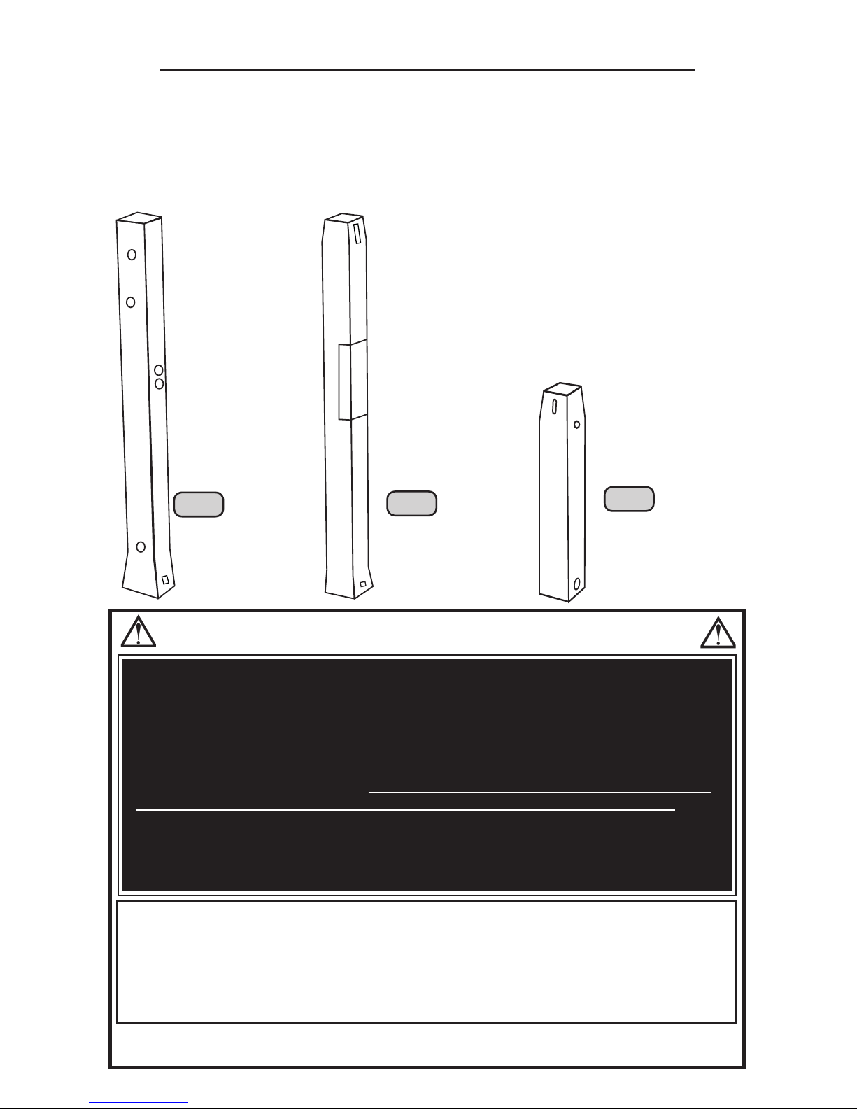
POLE SECTION IDENTIFICATION
Identify the pole sections before beginning assembly. Failure to
assemble the pole sections correctly may result in severe personal
injury or property damage as described on Page Two.
ONCE THE POLE SECTIONS HAVE BEEN SEATED, THEY
CANNOT BE SEPARATED.
TP
MP
BP
Top Pole:
Four holes at
the top of the
pole, four holes
in the middle,
two holes near
the bottom and
two small holes
at the bottom.
Bottom Pole:
Two slots at
the top of the
pole, two holes
near the top
and two holes
at the bottom.
Shortest pole.
Middle Pole:
Two slots at
the top of the
pole and two
small holes at
the bottom.
Warning
Sticker.
SAFETY INSTRUCTIONS
Most injuries are caused by misuse and/or not following instructions. Use
caution when using this system.
Owner must ensure that all players know and follow these rules for safe operation of
the system.
To ensure safety, do not attempt to assemble this system without following the
instructions carefully. Check entire box and inside all packing material for parts and/
or additional instruction material. Before beginning assembly, read the instructions
and identify parts using the hardware identier and parts list in this document.
Proper and complete assembly, use and supervision are essential for proper
orientation and to reduce the risk of accident or injury. A high probability of serious
injury exists if this system is not installed, maintained, and operated properly.
FAILURE TO FOLLOW THESE WARNINGS MAY RESULT IN SERIOUS INJURY OR
PROPERTY DAMAGE AND WILL VOID WARRANTY.
• If using a ladder during assembly, use extreme caution.
• Two capable adults are recommended for this operation.
• Check base daily for leakage. Leaks will cause system to fall.
• Assemble the pole sections properly. Failure to do so could cause the pole
sections to separate during play or transport.
• Minimum operational height is 7’6” (2.23m) to the rim.
4
RA
RD
RC
RF
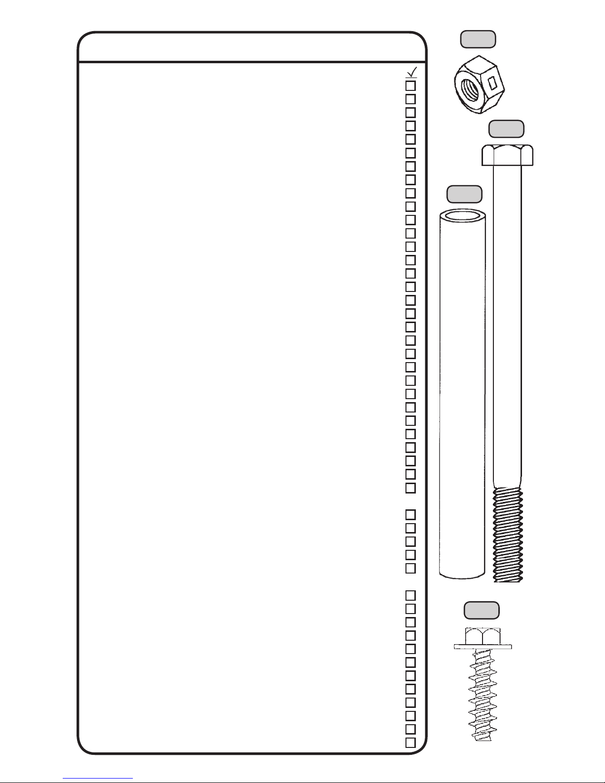
PARTS LIST
ID Part # Description Qty
TP 1030835 Top Pole 1
MP 1030836 Middle Pole 1
BP 1030837 Bottom Pole 1
RB 1030781 Right Backboard Bracket 1
LB 1030762 Left Backboard Bracket 1
AA C050016 Pole Cap 1
AB 502005 Net 1
AC 502027H Adjustment Handle 1
AD 502049G Trigger 1
AF CH05699 Rim Cover 1
AG 510022 Wheel 2
AH 510025 1/2” x 21 3/4” Axle 1
AI 510035 Base Cap 1
AJ CB01599 Base 1
AK CA00885 Zip Tie 2
AL 1030660 Spring Bracket 1
AM HA00800 Gas Spring 1
AN 1030669 Short Extension Arm 2
AO 1030667 Long Extension Arm 2
AP 1030758 Rear Lifter Arm 2
AQ ZA10185 Bellows 1
AR ZJ15386 Reactor ReboundTM Backboard 1
AS ZA73607 Power ShockTM Rim 1
AT 1030674 Pole Brace 2
AV ZA10907 Power ShockTM Outer Sleeve 1
AW ZA73707B Power ShockTM Inner Sleeve 1
AX 1018722 Power Shock
TM
Spring 1
AY AG00607 Backboard Weight 2
AZ ZA10607 Rim Tail Piece 2
FS16400 Warning Sticker (Applied) 1
AU F028009 Height Sticker 1
Reactor ReboundTM Backboard Hardware (HH07300C)
RA 302076 5/16” Centerlock Nut 2
RC BA04300 1/2” x 3.875” Spacer 2
RD 300069 5/16” x 4 1/2” Hex Bolt 2
RF BS00800 5/16” x 1” Screw (for plastic) 10
RG CF02299 1 1/2” Plug 2
Power ShockTM Rim Hardware (HH08200C)
PA BA02900 3/4” x 1” Spacer 2
PB BA02800 .69” x 1/2” Spacer 4
PC 302062 5/16” x 3 1/4” Hex Bolt 1
PD BA02610B Disc 1
PE BB04000 1/2” x 1 3/4” Bolt with patch 2
PF BB03100 1/2” x 3 3/4” Hex Bolt 1
PG 302008 3/8” Centerlock Nut 1
PH BB02900 3/8” x 2 1/4” Hex Bolt 1
PI BN01000 Coupler 1
PJ 301008 1/2” Centerlock Nut 3
PK 300073 1/2” Flat Washer 2
PL BB01800 1/2” x 7/8” Hex Bolt 2
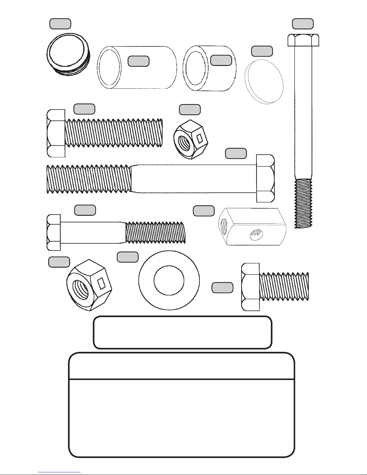
5
HARDWARE IS ACTUAL SIZE
(Unless otherwise indicated)
PA
RG
(Not actual
size)
PB
PC
PE
PD
(Not actual size)
PF
PG
PH
PI
PJ
PK
PL
(Not actual size)
**A MINIMUM OF TWO ADULTS
ARE REQUIRED FOR ASSEMBLY**
Tools and Materials Required for Assembly
(Not Included)
1. Adjustable Wrench
2. 3/8” Socket Wrench
3. 1/2” Wrenches (2)
4. 9/16” Wrenches (2)
5. 3/4” Wrenches (2)
6. 7/16” Wrenches (2)
7. Hammer or Mallet
8. Scrap Wood/Cardboard
9. 416 lb. Sand or Water
Supply
10. Scissors or Wire
Cutters
11. Pliers
12. Funnel
13. 3/4” Socket Wrench
14. Punch/Dowel
6
Before Beginning Assembly
A. Keep the hardware bags and their contents
separate. If any parts are missing, call our
Customer Service Department.
B. Test t all Bolts by inserting them into their
respective holes. If necessary, carefully scrape
away any excess powder coating buildup from
inside the holes. Do not scrape away all of the
powder coating. Bare metal may rust. You may
need to pound some Bolts into place with a
hammer or mallet.
ID Part # Description Qty
Main Hardware (HH07700C)
MB 300025 1/2” x 8” Hex Bolt 5
MC 300031 3/8” Flat Washer 2
MD 300043 Cotter Pin 1
ME 300055 1 1/2” Metal Pin 1
PJ 301008 1/2” Centerlock Nut 5
PG 302008 3/8” Centerlock Nut 2
MJ 302053 3/8” x 4” Hex Bolt 2
ML 500013 9/16” x .592” Spacer 4
MM 500015 3/8” x 1/2” Spacer 2
MN 500032 1/2” x 1/8” Spacer 4
MO 500081 Grease Packet 1
MS 800239 1/2” x 3 7/16” Spacer 2
MR 800328 3/4” x 4 1/5” Spacer 1
Handle Hardware (1017923)
HA 300101 Release Pin 1
HB 302007 3/8” x 6 1/2” Hex Bolt 2
HC 300187 1/2” x 6 1/2” Hex Bolt 1
PJ 301008 1/2” Centerlock Nut 1
PG 302008 3/8” Centerlock Nut 2
Base Hardware (HD9092C)
BA 300190 3/8” Cap Nut 1
BE 300030 5/16” x 1” Hex Bolt 2
MC 300031 3/8” Flat Washer 2
BB 300097 5/16” Nylock Nut 2
BC BB01900 3/8” x 4 1/4” Hex Bolt 1
BD 302014 5/16” Flat Washer 4
Pole Joint Hardware (HD9139)
JA 300121 1/4” x 4” Carriage Bolt 2
JB 300127 1/4” Cap Nut 2
PARTS LIST
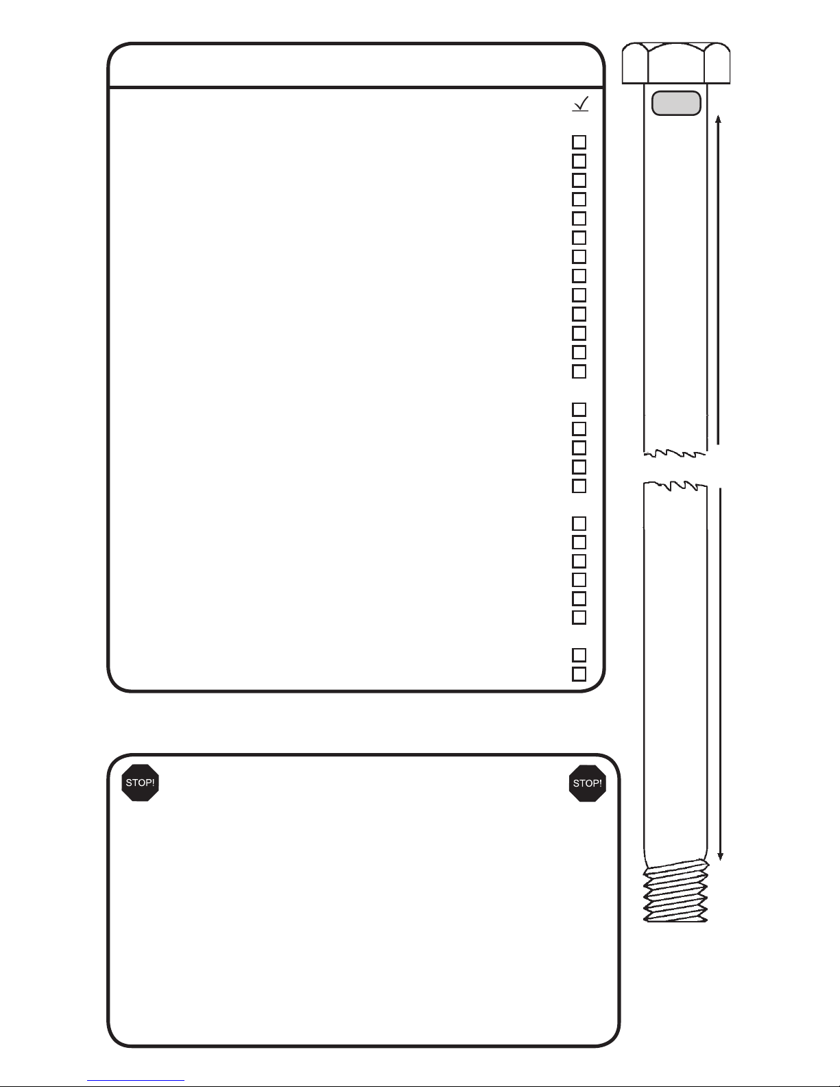
MB
8”
(Not actual
length)
7
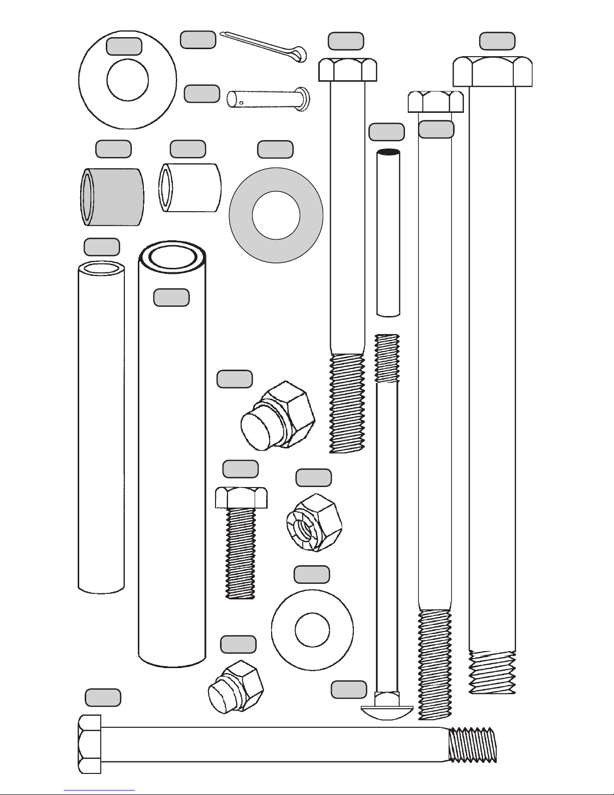
(Not actual size)
ME
MC
MJ
MS
MR
HA
HC
MNMM
HB
BA
ML
BB
BC
BD
BE
(Not actual size)
JB
JA
MD
8
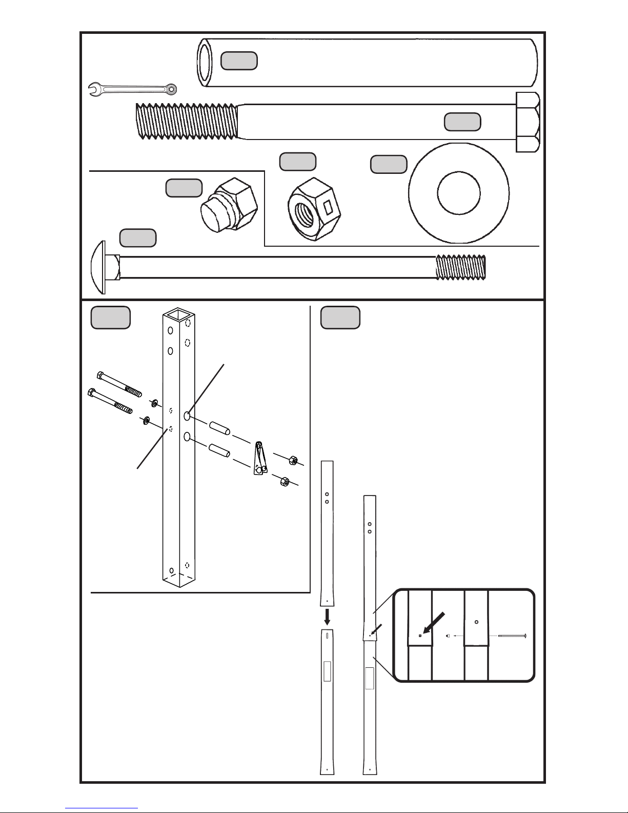
MJ
MS
PG
Required For
This Page:
9/16” Wrenches
HH07700C
(2)
(2)
JB
(2)
(1)
MJ
MS
AL
PG
Small
holes
Large
holes
Tighten all
hardware
securely.
MC
TP
1 2
MC
(2)
Do not jam the poles together
until instructed.
Only nger tighten
the Nut (JB).
Make sure the square portion
of the Bolt is completely inside
the square hole.
Line up the holes in the Top
Pole (TP) with the slots in the
Middle Pole (MP) and slide the
Top Pole over the Middle Pole.
The Cap Nut should be on the side
of the pole with the Spring Bracket.
HD9139
JA
The Warning Sticker
and Spring Bracket
should be on opposite
sides of the pole.
(1)
TP
MP
JA
JB
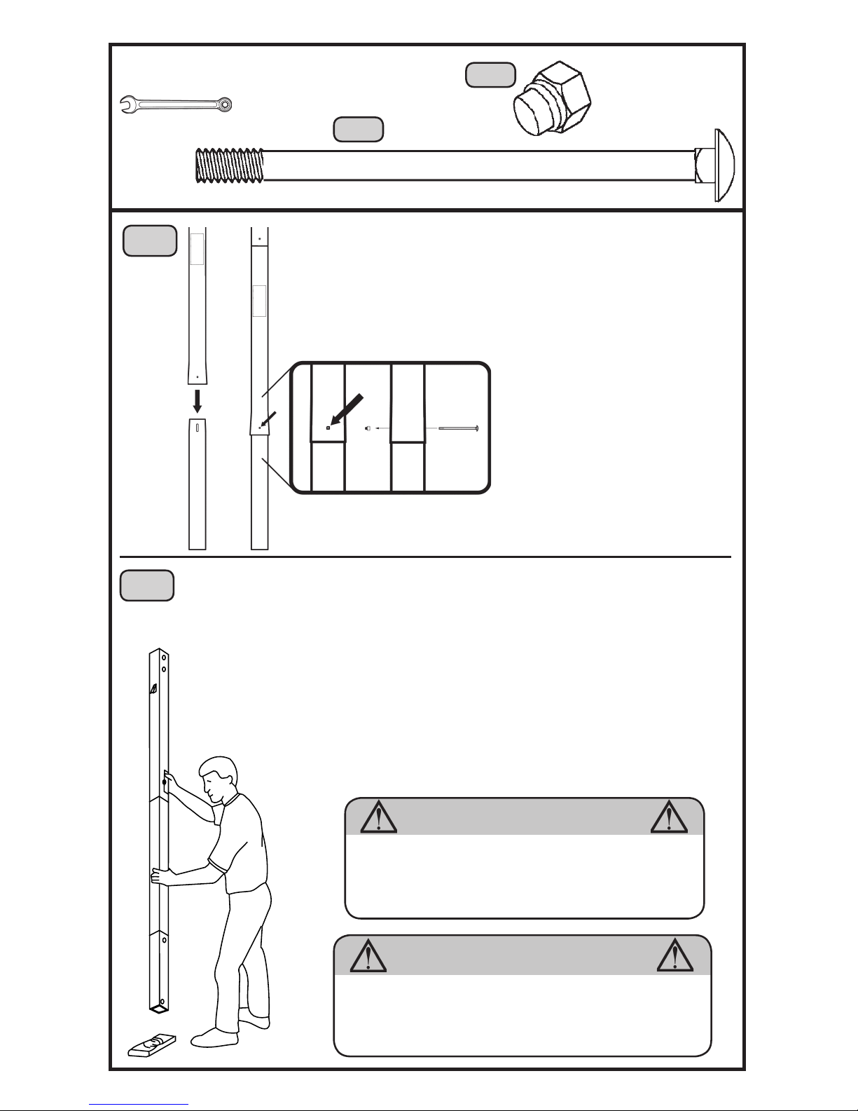
9
Required For This Page:
JA
(1)
HD9139
MP
BP
JA
4
This step cannot be reversed.
3
Line up the holes in the Middle Pole (MP)
with the slots in the Bottom Pole (BP) and
slide the Middle Pole over the Bottom Pole.
Make sure the square portion
of the Bolt is completely
inside the square hole.
Only nger tighten the Nut (JB).
Do not jam the poles together until instructed.
JB
The Cap Nut should be
on the side of the pole
with the Spring Bracket.
TP
BP
Strike each end of the pole rmly 5 to 6 times on a piece of
scrap wood or cardboard.
Do not hit your feet with the pole
sections, as serious injury could occur.
Tighten the Cap Nuts (JB) installed in steps 2
and 3. Make sure the Cap Nuts don’t break.
MP
WARNING
Failure to seat the pole sections together and secure
the Carriage Bolts could cause the pole sections to
separate, resulting in severe personal injuries as
listed on Page Two, or property damage.
If the end of the Bolt breaks through the plastic
cap, call our Customer Service Department at the
number on Page Two. Exposed threads on the
end of the Bolt may cause serious injuries.
WARNING
JB
(1)
7/16” Wrench
Scrap Wood
 Loading...