

Page 1

LifeSize® Gateway
Installation Guide
™
Page 2

March 2008
Copyright Notice
2008 LifeSize Communications Inc, and its licensors. All rights reserved.
LifeSize Communications has made every effort to ensure that the information contained in this
document is accurate and reliable, but assumes no responsibility for errors or omissions. Information
in this document is subject to change without notice. Companies, names, and data used in examples
herein are fictitious unless noted. This document contains copyrighted and proprietary information,
which is protected by United S tates copyright laws and international treaty provisions. No part of th e
document may be reproduced or transmitted, in any form or by any means, electronic or mechanical,
for any purpose, without the express written permission from LifeSize Communications.
Trademark Acknowledgments
LifeSize® is the trademark of LifeSize Communications Inc. All other trademarks ar e the pr op erty of
their respective owners.
Patent Notice
For patents covering LifeSize® products, refer to http://www.lifesize.com/support/legal
.
Contacting Customer Support
If you have questions, concerns, or need assistance, conta ct your LifeSize Channel Partner.
Providing Customer Feedback
LifeSize Communications welcomes your comments regarding our products and services. If you
have feedback about this or any LifeSize product, please send it to [email protected]
. Contact
information for LifeSize Communications is as follows:
Method Address
(512) 347-9300
Fax (512) 347-9301
Page 3

CONTENTS
About This Manual
Related Documentation vii
1 Functionality
About LifeSize Gateway Products 1
About the Gateway-PRI 1
About the Gateway-Serial 1
About Gateway Features 2
About LifeSize Gateway Applications and Topologies 8
About Multimedia Conferencing 9
About Point-to-Point Conferencing 10
About Multipoint Conferencing 10
About Gateway IP Network Connections 11
About Gateway ISDN Network Connections 11
About Gateway Encryption 13
About Conferencing via Leased Lines 14
About IP-to-Legacy MCU Conferencing 14
About LifeSize Gateway Functionality 15
About PRI Gateway Call Handling Capacity 15
About Gateway Call Bandwidth Overhead 15
Resource Allocation across E1/T1 Lines 16
About Peer-to-Peer Connectivity 16
2 Setting Up Your LifeSize Gateway
Physical Description 18
Front Panel 18
Contents iii
Page 4

Gateway-PRI Rear Panel 19
Gateway-Serial RTM 20
Preparing for Installation 20
Verifying the Package Contents 21
Mounting the LifeSize Gateway Unit in a 19-inch Rack 21
LifeSize Gateway Unit Initial Configuration 22
Connecting to a PC 23
Setting the IP Address 23
Changing the Configuration Tool Login Password 26
Connecting the LifeSize Gateway Unit to the LAN 27
Connecting Serial Lines to the Gateway 28
Serial Gateway Cable Connections and Pin-outs 28
Physical Description of DTE Cables 28
Data Interface Cable Pin-out Configurations 34
Data Interface Pin Layouts 36
DB-25 Connector 38
Signaling Interface Cable Pin-out Configuration 39
Signaling Interface Pin Layout 40
Managing and Monitoring the LifeSize Gateway Unit 41
SNMP Management 41
Local Port Monitoring Connections 41
Performing Software Upgrades 41
Accessing the LifeSize Gateway Administrator Interface 42
Registering the Online Help 43
3 Using the LifeSize Software Upgrade Utility
Introduction 45
Launching the Utility 46
Upgrading Software 46
4 Cable Connections and Pin-outs
Unit RS-232 9-Pin Serial Port 50
RJ-45 8-Pin IP Network Port 50
iv LifeSize Gateway Installation Guide
Page 5

RJ-45 Serial Port Adapter Cable 51
ISDN Port 51
5 Technical Specifications
Technical Specifications Table 53
Index 57
Contents v
Page 6

vi LifeSize Gateway Installation Guide
Page 7

ABOUT THIS MANUAL
The LifeSize Gateway Installation Guide describes how to install, configure and
monitor LifeSize Gateways.
RELATED DOCUMENTATION
The LifeSize Gateway documentation set is available on the LifeSize Utilities
and Documentation CD-ROM and includes manuals and online helps. The
manuals are available in PDF format.
Note You require Adobe Acrobat Reader version 5.0 or later to open the PDF
files. You can download Acrobat Reader free of charge from www.adobe.com.
This manual uses the following conventions:
Convention Description
Blue Headings in Upper Case Level 1 headings introducing major sections.
orange link
Pointing hand icon introduces a procedure.
Live links appear in orange.
About This Manual vii
Page 8

Page 9

1
FUNCTIONALITY
This section introduces the LifeSize Gateway, and includes the following topics:
About LifeSize Gateway Products About Gateway Features About LifeSize Gateway Applications and Topologies About LifeSize Gateway Functionality
ABOUT LIFESIZE
G
ATEWAY
P
RODUCTS
ABOUT THE
ATEWAY-PRI
G
ABOUT THE
ATEWAY-SERIAL
G
LifeSize Gateway series consists of the following products:
Gateway-PRI (see About the Gateway-PRI) Gateway-Serial (see About the Gateway-Serial)
The Gateway-PRI enables audio, video, and data communication between
H.320 endpoints that connect through ISDN, and H.323 endpoints that connect
through a packet-based network. For voice-over-IP, the Gateway-PRI enables
PSTN voice callers to connect from the ISDN network to IP voice callers. The
Gateway-PRI supports two PRI ISDN ports.
The Gateway-Serial supports multimedia conferencing over IP by translating
between H.323 and serial protocols. With the help of an Imux, the LifeSize
Gateway can also translate between H.323 and H.320 protocols.
The LifeSize Gateway offers a serial leg for multimedia conferencing over IP by
providing an interface for legacy endpoints with serial interfaces,
encryption/decryption devices, satellite networks and leased line services.
Functionality 1
Page 10

About Gateway Features
ABOUT GATEWAY
FEATURES
Table 1-1 lists the major features of the LifeSize Gateway.
Table 1-1 Gateway Feature Summary
Feature Description
Interoperability The LifeSize Gateway provides a high degree of
interoperability with other H.323 compliant gateways,
gatekeepers, terminals, proxy, and Multipoint Control
Unit (MCU) products by being based on the H.320
standard and H.323 protocol stack.
Web-based management The LifeSize Gateway features the LifeSize Gateway
interface. This is a web interface used to configure and
monitor the LifeSize Gateway. You can view and modify
all aspects of the LifeSize Gateway configuration from a
remote location using a Java-enabled web browser.
SNMP management The LifeSize Gateway features Simple Network
Management Protocol (SNMP) management that
supports all aspects of monitoring, diagnostics,
configuration, and trapping.
Diagnostics The LifeSize Gateway features front and rear panel LED
indicators that display status for the unit. You can also
access remote diagnostics of the unit through the
LifeSize Gateway interface, Telnet, SNMP, or a serial
port.
Network load balancing The LifeSize Gateway supports load balancing on the
T.120 data collaboration The LifeSize Gateway supports data transfers in calls
Quality of service (QoS) T he LifeSize Gateway features configurable coding of
2 LifeSize Gateway Installation Guide
network by communicating with a gatekeeper through
H.323 RAI (Resource Available Indication)/RAC
(Resource Available Confirmation) messages.
between ISDN and IP by using high speed T.120 in
HMLP and VarMLP formats.
media packets to achieve QoS routing priority on the
Internet Protocol (IP) network. The T ype of Service
(To S) bits of the IP datagram header can be configured
for priority level.
Page 11

About Gateway Features
Table 1-1 Gateway Feature Summary (continued)
Feature Description
Dial plan The LifeSize Gateway supports a simplif ied dial plan for
outbound dialing using a single universal prefix. Using
the dial plan, the LifeSize Gateway automatically detects
the capabilities received in the Setup message from the
IP endpoint and sets the same bit rate for the ISDN (or
serial interface) side of the call.
Direct dialing and call routing The LifeSize Gateway dial plan supports the following
direct dialing and call routing facilities:
Direct Inward Dialing (DID)
Multiple Subscriber Network (MSN)
Q.931 Sub-addressing Information
Element
Gateway-Serial supports DID in DCE mode
only.
Internal and External Interactive Voice
Response (IVR)
TCS4
Default extension
Access control The LifeSize Gateway features password-controlled
access to the LifeSize Gateway interface. Up to ten
different administrator ac cess profiles can be defined for
the LifeSize Gateway.
DTMF translation The LifeSize Gateway supports translation between
in-band Dual Tone Multi-Frequency (DTMF) signals (on
the ISDN side) and out-of-band H.245 messages (on the
IP side). DTMF translation occurs for voice and video
calls.
Dual video The LifeSize Gateway supports H.239 standards-based
dual video and T ANDBERG DuoV ideo technology. Dual
video streams enable a screen to carry video images from
one source while simultaneously displaying images from
a second source.
Functionality 3
Page 12

About Gateway Features
Table 1-1 Gateway Feature Summary (continued)
Feature Description
Conceal caller ID The LifeSize Gateway supports a conceal caller ID
feature that instructs the gatekeeper to conceal the
identity of the calling endpoint on the IP or ISDN
network, whether the presentation restricted feature is
enabled or not.
H.323 fast start The LifeSize Gateway H.323 fast start feature enables
endpoints to join a voice conference in the LifeSize
Gateway more quickly.
ISDN rollover (available in
Gateway-PRI only)
The LifeSize Gateway features ISDN rollover. In this
feature, the LifeSize Gateway sends a “busy out” channel
request to the PSTN switch when the current PRI
connection is left with less than a predefined number of
available B channels. The PSTN switch “rolls over” to
the next available gateway.
Network Specific Facility
(available in Gateway-PRI
only)
The LifeSize Gateway provides support for Network
Specific Facility Information Elements (NSF IEs) which
enable system administrators to specify to service
providers the equipment, service, or network through
which they want a call routed.
ISDN connection failure The LifeSize Gateway responds to ISDN connection
failure events, by unregistering from its gatekeeper. The
gatekeeper is forced to send new IP-to-ISDN calls
through a different gateway, thus ensuring high call
completion rates. The LifeSize Gateway re-registers to
the gatekeeper when the ISDN connection is restored.
Downspeeding The LifeSize Gateway features downspeeding
functionality. In the downspeeding feature, the LifeSize
Gateway attempts to reconnect a disconnected video call
either at a lower bandwidth or as a voice call.
Downspeeding contributes to a higher percentage of call
completion on the network. The LifeSize Gateway
supports downspeeding at call setup and in mid-call.
Multiple trap server support The LifeSize Gateway supports up to three SNMP trap
4 LifeSize Gateway Installation Guide
servers.
Page 13

About Gateway Features
Table 1-1 Gateway Feature Summary (continued)
Feature Description
H.239 support The LifeSize Gateway supports the H.239 protocol in
ISDN-to-IP calls and in IP-to-ISDN calls.
Encryption support The LifeSize Gateway supports H.235-compliant AES
128 encryption for calls over IP networks, and H.233 and
H.234-compliant AES 128 encryption for calls over
ISDN networks.
H.243 Conference Control
support
The LifeSize Gateway supports the H.243 protocol in
ISDN-to-IP calls and in IP-to-ISDN calls. The LifeSize
Gateway identifies the protocol version that an IP
endpoint uses and sends H.239 capabilities only to those
endpoints working with protocol version 4.0 or later.
Peer-to-peer connectivity The LifeSize Gateway supports connectivity to the IP
network through a gatekeeper, or directly to a peer
device.
IP network connections The LifeSize Gateway has one 10/100Base-T Ethernet IP
port (on the front panel) and connects to an IP segment
through a direct connection to a network switch.
Table 1-2 lists features for specific LifeSize Gateways.
Table 1-2 LifeSize Gateway Feature Specifics
Feature Gateway-PRI Gateway-Serial
Supported ports 2 PRI ISDN ports 4 serial ports
Supported video
conferencing protocols
Supported audio codecs The term audio transcoded video calls refers to the process whereby an audio stream in a
multimedia call can be transcoded from one codec type to another.
Basic and advanced audio coding supported codecs: G.711, G.722, G.722.1, G.723.1, G .728
H.320, H.323 (v4.0)
Audio Transcoding G.711 (ISDN) < > G.723.1 (IP) for up to 60
voice channels.
Transcoding for the 4 supported multimedia
calls.
Functionality 5
Page 14

About Gateway Features
Table 1-2 LifeSize Gateway Feature Specifics (continued)
Feature Gateway-PRI Gateway-Serial
G.711 (IP) < > G.728 (ISDN) for up to 20
audio transcoded video channels.
The LifeSize Gateway automatically
performs A-Law G.711-to-µ-Law G.711
translation between the IP and ISDN sides if
needed.
Note When your LifeSize unit includes
both a LifeSize Gateway and a LifeSize
Multipoint, G .728 transcoding is supported on
the LifeSize Multipoint only.
Supported video protocols H.261, H.263, H.263+ (Annexes F, J and N), H.263++ (Annex W), H.264
Supported video resolutions VGA, XGA, SVGA, SIF, 4SIF, CIF, QCIF, 4CIF, 16CIF
Supported bandwidths
(Kbps)
56, 64, 112, 128, 168, 192, 224, 256, 280, 320,
336, 384, 448, 512, 672, 768, 1288, 1472,
Note Bandwidth rates of 256 Kbps and up support the G.722 audio codec.
6 LifeSize Gateway Installation Guide
1680 and 1920
56, 64, 112, 128, 168, 192, 224, 256, 280,
320, 336, 384, 448, 512, 672, 768, 1288,
1472 and 1920
Page 15

Table 1-2 LifeSize Gateway Feature Specifics (continued)
Feature Gateway-PRI Gateway-Serial
About Gateway Features
Call handling capabilities For 1 x PRI T1 line:
23 ports (voice)
1 call per serial connection, up to a maximum
bandwidth of 1920 Kbps per port.
23 ports 1B (video and data)
11 ports 2B (video and data)
3 ports 6B (video and data)
For 2 x PRI T1 lines:
46 ports (voice)
30 ports 1B (video and data)
23 ports 2B (video and data)
7 ports 6B (video and data)
For 1 x PRI E1 line:
30 ports (voice)
30 ports 1B (video and data)
15 ports 2B (video and data)
5 ports 6B (video and data)
For 2 x PRI E1 lines:
60 ports (voice)
30 ports 1B/2B (video and data)
10 ports 6B (video and data)
Line quality Supports line echo cancellation, H.323 Fast
Start and DTMF detection for voice and
Supports line echo cancellation and DTMF
detection for voice calls.
video calls.
IP network connection I10/100Base-T Ethernet IP UTP connection (on the front panel).
Serial control port (DB-9)
connection
RS-232 DTE 9-pin D-type connection on front panel for connection to a PC terminal or an
external modem.
Supported media protocols N/A V.35, RS-449, EIA-530, EIA-530A
Supported signaling
protocols
5ESS and 4ESS, DMS100, National ISDN,
Euro-ISDN, VN6 Dialing (France), NTT
RS-366, Manual Control, Data Triggered.
(Japan), Hong Kong Dialing (Hong Kong),
Support for Taiwan PRI system.
Supported media + signaling
combinations
N/A RS-449 + RS-366
V.35 + RS-366
EIA-530 + RS-366
EIA-530A + RS-366
Functionality 7
Page 16

About LifeSize Gateway Applications and Topologies
Table 1-2 LifeSize Gateway Feature Specifics (continued)
Feature Gateway-PRI Gateway-Serial
Encryption interoperability N/A KIV-7, KG-194
PRI interface Configurable E1/T1 PRI network interface.
Support for fractional E1/T1 channel
selection.
Configurable as terminal side (TE) or
network side (NT) device.
Configurable Long Haul PRI module
(supported in Japan only).
Switch information Numbering Plan Identifier (NPI), Type of
Number (TON) and Network Specific
Facility (NSF) information elements are
configurable per PRI port.
Bonding calls Internal Imux providing calls at 128 Kbps
(2B) up to full PRI of 1472 Kbps (23B) for
T1 and up to full PRI of 1920 Kbps (30B) for
E1 using bonding mode 1.
Parallel dialing for bonded calls.
Internal IVR capacity 30 simultaneous calls 4 simultaneous calls
ABOUT LIFESIZE
GATEWAY
A
PPLICATIONS AND
T
OPOLOGIES
The LifeSize Gateway supports multimedia conferencing by translating between
H.323 and H.320 protocols. Examples of network applications that use the
LifeSize Gateway include:
Multimedia conferencing (see About Multimedia Conferencing on
N/A
N/A
N/A
page 9)
Point-to-Point conferencing (see About Point-to-Point Conferencing
on page 10)
Multipoint conferencing (see About Multipoint Conferencing on
page 10)
IP networking (see About Gateway IP Network Connections on
page 11)
ISDN networking (see About Gateway ISDN Network Connections
on page 11)
8 LifeSize Gateway Installation Guide
Page 17
About LifeSize Gateway Applications and Topologies
IP phone
H.323
terminal
ISDN
ISDN
phone
regular
phone
PSTN
LifeSizeGateway
IP
network
H.323
terminal
H.320
terminal
Encrypted videoconferencing (see About Gateway Encryption on
page 13)
Conferencing over leased lines (see About Conferencing via Leased
Lines on page 14)
Communicating with legacy MCU equipment (see About
IP-to-Legacy MCU Conferencing on page 14)
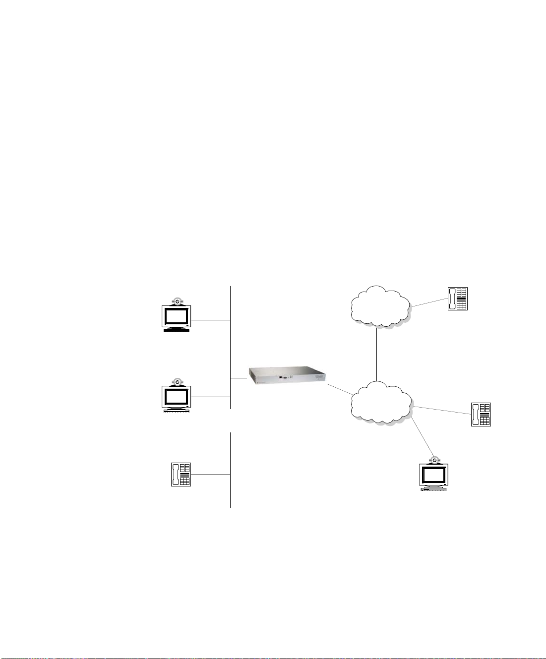
ABOUT MULTIMEDIA CONFERENCING
The LifeSize Gateway-PRI enables H.323 endpoints on the IP network to
communicate with an H.320 terminal, an ISDN phone, or a regular phone on a
circuit-switched public network without having to connect directly to these
networks. The LifeSize Gateway allows all IP network terminals to support
video conferences without connecting every desktop computer to an ISDN line
(see Figure 1-1).
Figure 1-1 Multimedia Conferencing through the Gateway
Typical multimedia conferencing applications include:
Business video conferencing
Distance learning
Telemedicine
Functionality 9
Page 18
About LifeSize Gateway Applications and Topologies
IP network
LifeSizeGateway
ISDN
H.323
terminal
H.320
terminal
Video-enabled call centers
Telecommuting
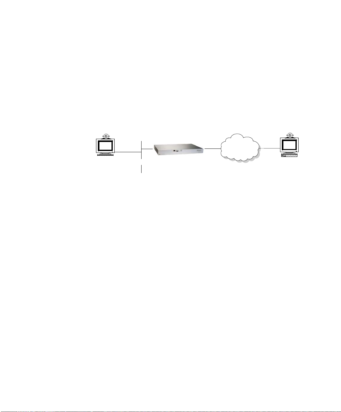
ABOUT POINT-TO-POINT CONFERENCING
ABOUT MULTIPOINT CONFERENCING
The LifeSize Gateway-PRI enables direct video, voice, and data communication
between an H.320 (ISDN) terminal and H.323 (IP) terminals at bandwidths of
up to 1472 Kbps (23B bonding for T1) and up to 1920 Kbps (30B bonding for
E1) (see Figure 1-2).
Figure 1-2 Point-to-Point Conferencing through the Gateway
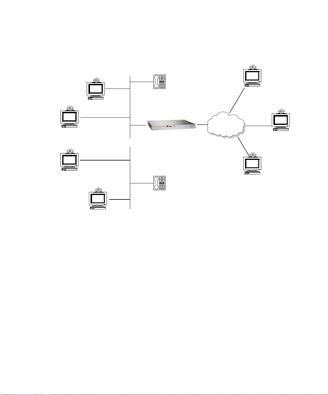
T ogether with the LifeSize Multipoint, the LifeSize Gateway-PRI enables H.320
ISDN terminals to participate in a mixed ISDN-IP multipoint multimedia
conference with IP network endpoints (see Figure 1-3).
For example, when an H.320 ISDN terminal wants to participate in a multipoint
conference with H.323 IP endpoints, the H.320 ISDN terminal can either join
the multipoint conference by dialing to the LifeSize Gateway, or be invited into
the conference by one of the participating IP endpoints. In either case, the
LifeSize Gateway connects the ISDN terminal to the LifeSize Multipoint,
enabling it to participate in the multipoint conference.
10 LifeSize Gateway Installation Guide
Page 19
About LifeSize Gateway Applications and Topologies
IP network
IP phone
ISDN
LifeSize Gateway
LifeSize Multipoint
IP phone
H.323
terminal
a
H.323
terminal
H.323
terminal
H.323
terminal
H.320
terminal
H.320
terminal
H.320
terminal
Figure 1-3 Mixed ISDN-IP Multipoint Multimedia Conference
ABOUT GATEWAY IP
NETWORK
ONNECTIONS
C
ABOUT GATEWAY
ISDN NETWORK
C
ONNECTIONS
The LifeSize Gateway-PRI features one 10/100Base-T Ethernet IP port (on the
front panel) and connects to an IP segment through a direct connection to a
network switch.
The LifeSize Gateway-PRI features configurable E1/T1 PRI ISDN connections.
When configured as an E1 connection, each port provides 30 B channels and
one D signaling channel. When configured as a T1 connection, each port
provides 23 B channels and one D signaling channel. The type of line available
depends on your local ISDN provider. You configure the LifeSize Gateway PRI
port to an E1 or T1 interface accordingly. In addition, you can choose to activate
only specific channels by using fractional channel selection.
Functionality 11
Page 20
About LifeSize Gateway Applications and Topologies
PRI T 1/E1
Central Office
Switch
Private Public
H.323 term inal
LifeSize Gateway
IP phone
IP network
PRI T1/E1
Central Office
Switch
Private Public
H.323 term inal
IP phone
LifeSize Gateway
IP network
PBX
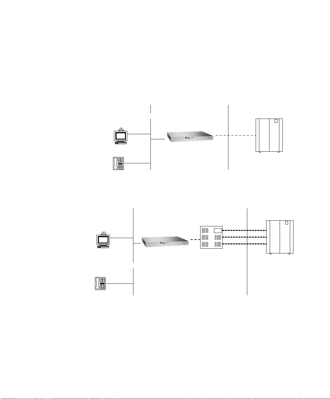
PRI GATEWAYS You can connect the Gateway-PRI directly to a PRI line prov id ed by your local
ISDN provider (as shown in Figure 1-4), or to a local private branch exchange
(PBX) that provides the PRI connection (as shown in Figure 1-5).
Figure 1-4 Connecting the PRI Gateway Directly to a Central
Office Switch
Figure 1-5 Connecting the PRI Gateway to a PBX that Provides a
PRI Line
12 LifeSize Gateway Installation Guide
Page 21
About LifeSize Gateway Applications and Topologies
ISDN
latigid
RS-366 RS-366
EIA-530A EIA-530A
isolator
KIV-7
IMUX
ISDN
DTE
DCE
LifeSize Gateway -Serial
IP network
H.323
endpoint
H.323
endpoint
H.323
endpoint
H.323
endpoint
serial
LifeSizeGateway - Serial
IP network
H.323
endpoint
H.323
endpoint
H.323
endpoint
KIV-7 satelite access
DTE DCE
H.323
endpoint
ABOUT GATEWAY
NCRYPTION
E
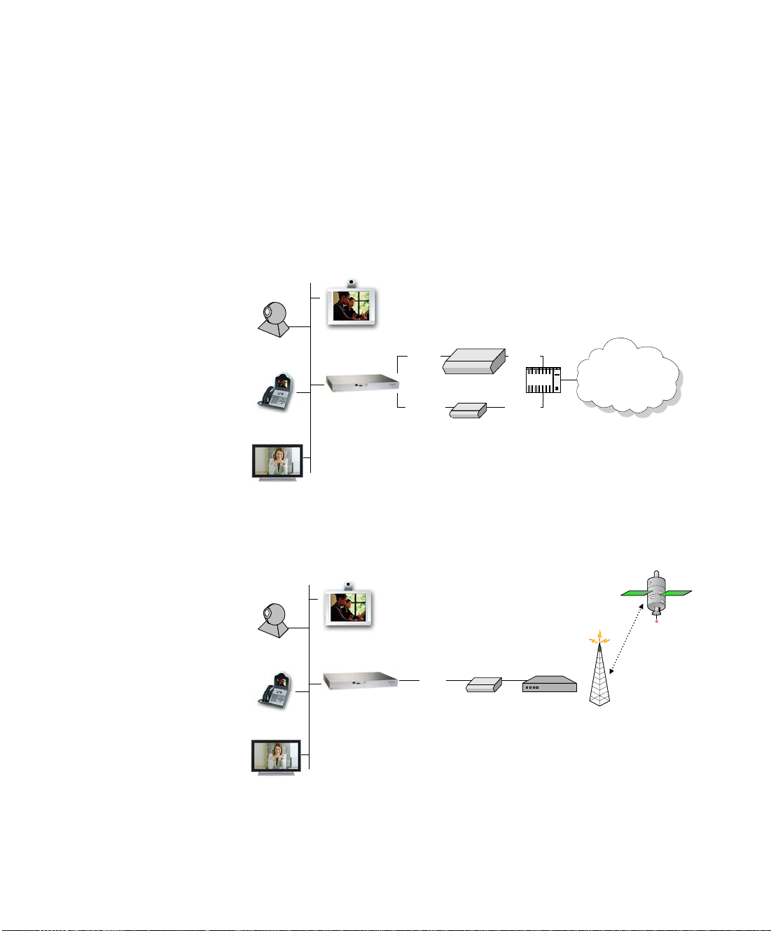
The Gateway-Serial enables encrypted videoconferencing between H.323
endpoints on the IP network and endpoints on remote sites by connecting to
external encryption/decryption devices via serial interfaces (as shown in
Figure 1-6). The Gateway-Serial also enables encrypted vi deoconferencing via
satellite with or without RS-366 signaling (as shown in Figure 1-7).
Figure 1-6 Encrypted Videoconferencing
Figure 1-7 Encrypted Videoconferencing via Satellite
Functionality 13
Page 22
About LifeSize Gateway Applications and Topologies
V.35
adaptor adaptor
leased
line
LifeSize Gateway - Serial
IP network
H.323
endpoint
H.323
endpoint
H.323
endpoint
DTE
V.35
DCE DTE
LifeSize Gateway - Serial
IP network
DCE
H.323
endpoint
DTE
ISDN
ISDN
V.35
latigid
IMUX
V.35
V.35 V.35
legacyMCU
LifeSize Gateway -Serial
IP network
H.323
endpoint
H.323
endpoint
H.323
endpoint
DCE
H.323
endpoint
ABOUT CONFERENCING
VIA LEASED LINES
ABOUT IP-TO-LEGACY
MCU C
ONFERENCING
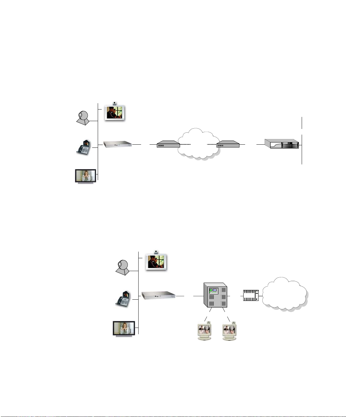
The Gateway-Serial enables conferencing between H.323 endpoints on IP
networks connected via a leased line (as shown in Figure 1-8).
Figure 1-8 Conferencing via Leased Lines
The Gateway-Serial provides an IP-to-serial interface for communication with
legacy MCU equipment (as shown in Figure 1-9).
Figure 1-9 IP-to-Serial Interface Communication via Legacy MCU
14 LifeSize Gateway Installation Guide
Page 23

About LifeSize Gateway Functionality
ABOUT LIFESIZE
GATEWAY
F
UNCTIONALITY
ABOUT PRI GATEWAY
CALL HANDLING
APACITY
C
This section discusses the following topics:
About PRI Gateway Call Handling Capacity on page 15 About Gateway Call Bandwidth Overhead on page 15 About Peer-to-Peer Connectivity on page 16
Table 1-3 lists the maximum call handling capacity of the Gateway-PRI for
different types of calls.
Table 1-3 PRI Gateway Call Handling Capacity
Call Type Maximum
Number of
Calls Using
1 x E1 PRI
Line
voice (64 Kbps) 30 23 60 46
2B video (128 Kbps) 15 11 30 23
6B video (384 Kbps) 5 3 10 7
12B video (768 Kbps) 2 1 5 3
Maximum
Number of
Calls Using
1 X T1 PRI
Line
Maximum
Number of
Calls Using
2 x E1 PRI
Lines
Maximum
Number of
Calls Using
2 x T1 PRI
Lines
ABOUT GATEWAY
CALL BANDWIDTH
VERHEAD
O
Note Enabling ISDN-to-IP DTMF detection in the Gateway-PRI for video calls
reduces the number of supported calls by half.
According to the H.320 standard, the available bandwidth allocated to a call at
any given bit rate will always be slightly less than the stated maximum for the
following reasons:
All stated maximum call bandwidths include provision for control,
audio, video, and data traffic.
Video traffic on the ISDN side contains additional bits for error
correction purposes which also consume bandwidth. V id eo traff ic on
the IP side does not include this additional load.
Opening an audio channel further reduces the bandwidth available to
the video traffic.
Functionality 15
Page 24

About LifeSize Gateway Functionality
For example, a call at 384 Kbps actually has only 363 Kbps available to it.
Control and error correction account for the remaining 21 Kbps.
RESOURCE ALLOCATION ACROSS E1/T1 LINES
ABOUT PEER-TO-PEER
ONNECTIVITY
C
The LifeSize Gateway can allocate bandwidth resources to calls across separate
E1 or T1 connections to maximize bandwidth capacity in cases where there is
not enough capacity for a call on a single E1 or T1 connection, but where
sufficient capacity does exist when remaining capacity on both E1/T1 lines is
combined.
For example, a LifeSize Gateway using two T1 lines can support three 6B calls
on each T1 line, with 320 Kbps spare capacity per line:
Each T1 line provides 23 B channels.
Each B channel supports 64 Kbps
Each T1 line supports 23 x 64 = 1472 Kbps
Each 6B call requires 6 x 64 = 384 Kbps
Each T1 line supports 1472/384 = 3 6B calls + 320 Kbps spare
The LifeSize Gateway processes an additional 6B call requiring a further 384
Kbps by taking bandwidth resources from each of the two T1 lines, both of
which have 320 Kbps available. In this way, the LifeSize Gateway spreads the
call over both T1 lines.
The LifeSize Gateway supports the following types of connectivity to the IP
network
Through a gatekeeper
Directly to a peer device such without the need for a gatekeeper.
16 LifeSize Gateway Installation Guide
Page 25

2
SETTING UP YOUR LIFESIZE GATEWAY
This section introduces the LifeSize Gateway solution and details the
components that LifeSize Gateway includes, and includes the following topics:
Physical Description
Preparing for Installation
Verifying the Package Contents
Mounting the LifeSize Gateway Unit in a 19-inch Rack
LifeSize Gateway Unit Initial Configuration
Connecting the LifeSize Gateway Unit to the LAN
Connecting Serial Lines to the Gateway
Serial Gateway Cable Connections and Pin-outs
Managing and Monitoring the LifeSize Gateway Unit
Accessing the LifeSize Gateway Administrator Interface
Registering the Online Help
Setting Up Your LifeSize Gateway 17
Page 26
Physical Description
PHYSICAL
This section provides a physical description of the LifeSize Gateway units.
DESCRIPTION
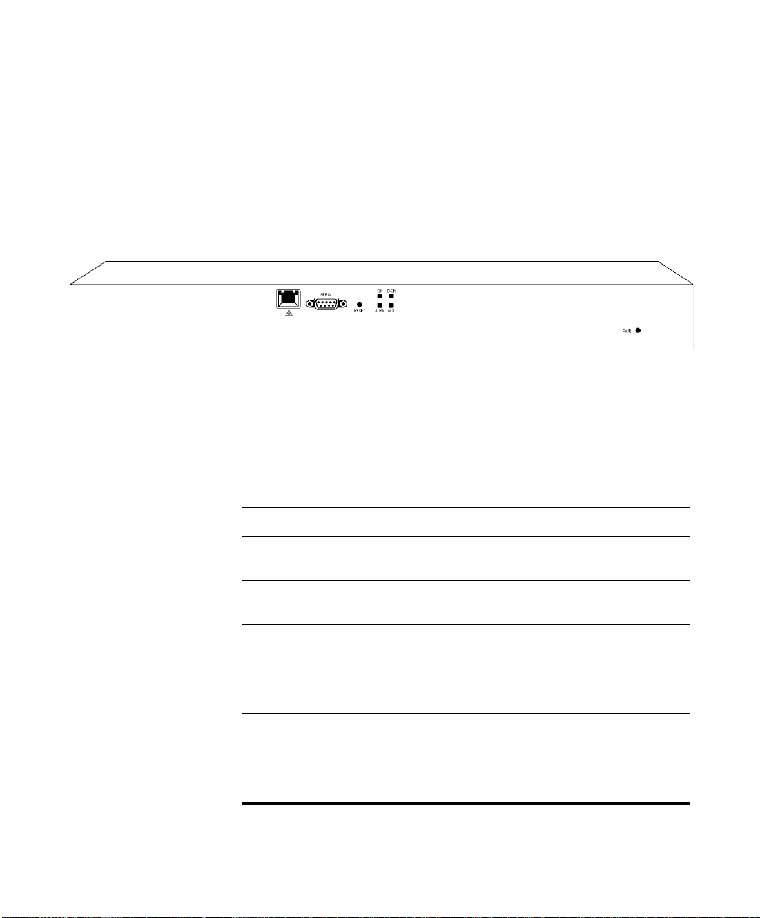
FRONT PANEL Figure 2-1 shows the front panel of the LifeSize Gateway unit. Table 2-1
describes the components of the front panel.
Figure 2-1 LifeSize Gateway Front Panel
Table 2-1 Front Panel Components
Component Description
Ethernet connector An RJ-45 connector that provides the primary Ethernet
connection for the IP network port.
SERIAL connector A DB-9 connector that allows you to connect a PC
terminal for local configuration.
RST button Allows you to reset the LifeSize Gateway unit manually.
GK LED Lights green when the LifeSize Gateway unit is registered
D-Ch LED Lights green when a PRI or serial line is enabled and a
ACT LED Lights green to indicate that there are active calls in the
ALRM LED Lights green to indicate that an error has occurred and the
ETHERNET LEDs The top part of the Ethernet connector contains two LED
18 LifeSize Gateway Installation Guide
with a gatekeeper.
carrier signal is detected
LifeSize Gateway unit.
LifeSize Gateway unit requires resetting.
indicators. The left-hand LED lights green when the local
IP network link is active. The right-hand LED lights green
if the connection speed is 100 Mbps, and is off when the
connection speed is 10 Mbps.
Page 27
Physical Description
GATEWAY-PRI REAR
ANEL
P
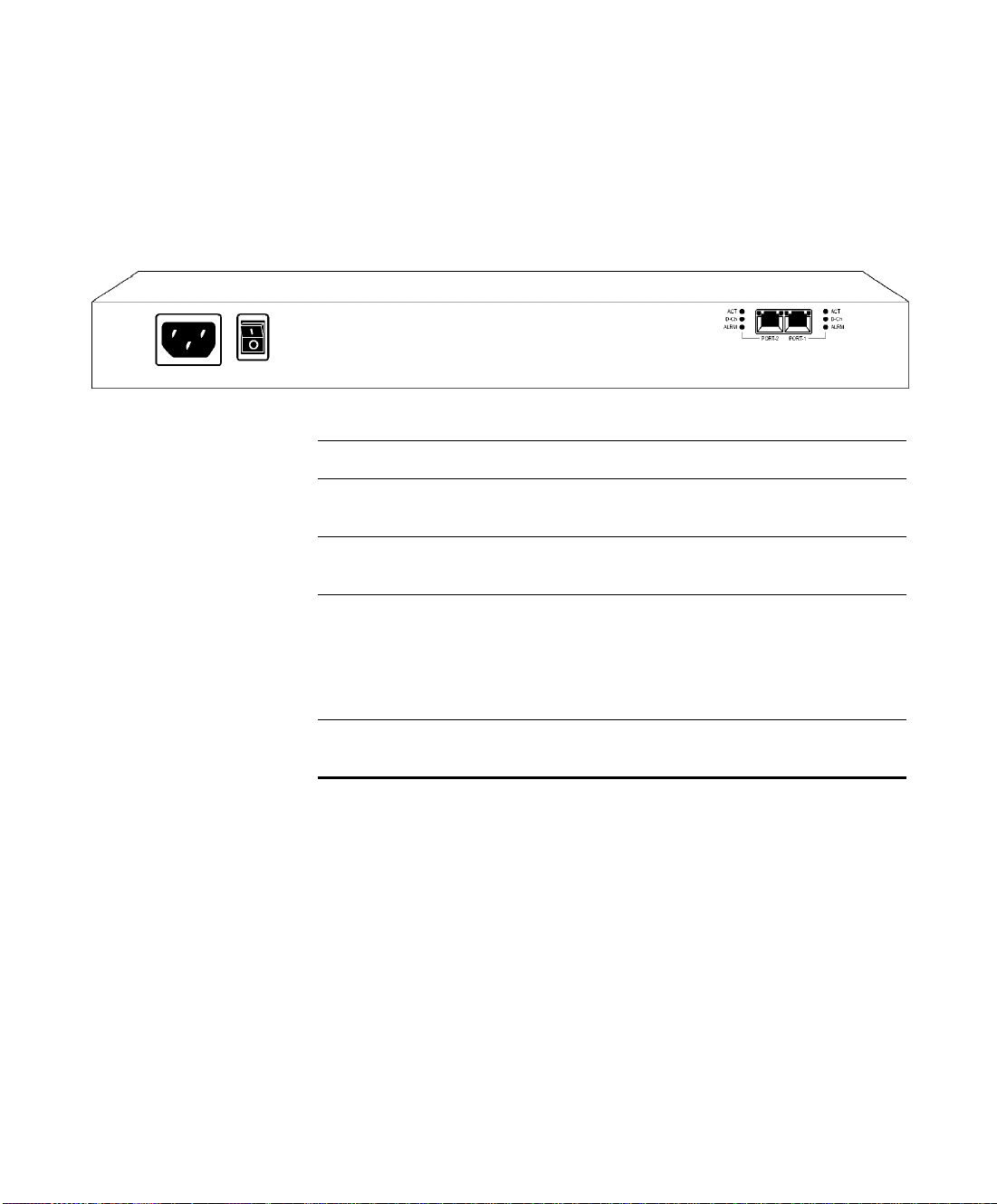
Figure 2-2 shows the rear panel components of the Gateway-PRI unit. Table 2-2
describes these components.
Figure 2-2 Gateway-PRI: Rear Panel
Table 2-2 Gateway-PRI Rear Panel Components
Component Description
ACT LEDs Lights green to indicate that there are active calls in the
LifeSize Gateway on the specified PRI line.
D-Ch LEDs Lights green to indicate that the PRI line is enabled and a
carrier signal is detected.
ALRM LEDs Displays alarm events for the PRI line.
YELLOW—Lights yellow when there is a loss
of frame alignment at the remote side.
ORANGE—Lights orange when there is a loss of
frame alignment in the LifeSize Gateway.
PRI LINE connectors RJ-45 connectors that provide the PRI line connections for
the specified LifeSize Gateway ISDN PRI port.
Setting Up Your LifeSize Gateway 19
Page 28
Preparing for Installation
GATEWAY-SERIAL RTM
PREPARING FOR
INSTALLATION
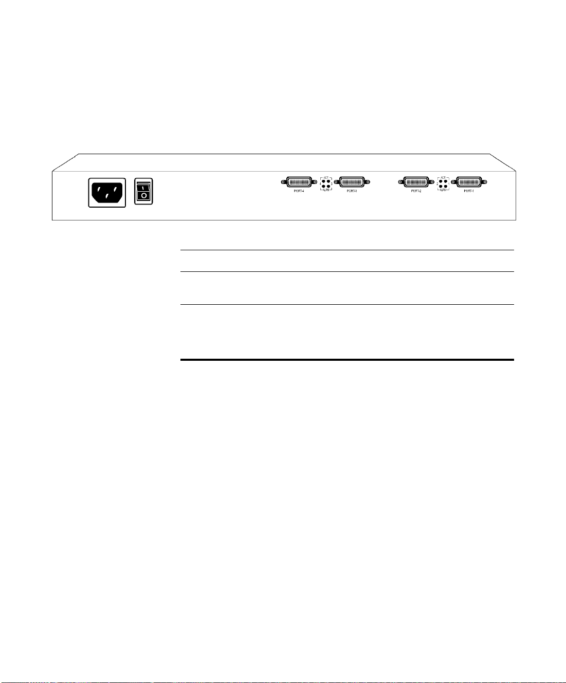
Figure 2-3 shows the rear panel components of the Gateway-Serial unit.
Table 2-3 describes these components.
Figure 2-3 Gateway-Serial: Rear Panel
Table 2-3 Gateway-Serial Rear Panel Components
Component Description
PORT connectors DB-60 connectors that provide the serial line connections
for LifeSize Gateway serial ports 1 to 4.
ACT and ALRM LEDs ACT lights green to indicate that the specified serial line is
currently in use.
ALRM lights red to indicate an internal error related to the
specified line.
This section describes the requirements for installing the LifeSize Gateway unit.
Proper clearance at the sides of the unit to allow adequate ventilation,
and at least 20 cm clearance at the back of the unit to allow access to
cable connections
A PC with a serial port and terminal emulation software to assign the
LifeSize Gateway unit an IP address
Dedicated IP address for the LifeSize Gateway unit
The IP address of the router that the LifeSize Gateway unit will use
to communicate across the network
For an H.323 environment, the IP address of the H.323 gatekeeper
with which you want the LifeSize Gateway unit to register
Available IP network ports on the switch for the LifeSize Gateway
unit
A grounded AC power outlet
A 10BaseT or 100BaseT LAN cable
20 LifeSize Gateway Installation Guide
Page 29

Verifying the Package Contents
VERIFYING THE
P
ACKAGE
C
ONTENTS
MOUNTING THE
LIFESIZE GATEWAY
U
NIT IN A 19-INCH
R
ACK
Ambient room temperature range of 32
Non-condensing relative humidity range of 5% to 90%
o
to 104oF (0o to 40oC)
Inspect the contents of the box for shipping damage. Report any damage or
missing items to your distributor or reseller. Table 2-4 lists the package contents
for the LifeSize Gateway unit.
Table 2-4 Package Contents with LifeSize Gateway Unit
Product Contents
Gateway-PRI or
Gateway-Serial unit
LifeSize Gateway Unit
Power cable (depending on customer location)
Terminal cable
LAN cable
Rack mounting kit (two brackets and six screws)
Four rubber feet
LifeSize Gateway CD-ROM containing product
documentation, utilities and online help files.
You can optionally mount the LifeSize Gateway unit in a standard 19-inch rack.
T wo mounting brackets and a set of screws are included in the LifeSize Gateway
unit shipping box.
Procedure
1 Disconnect all cables including the power cables.
2 Place the LifeSize Gateway unit right-side up on a hard flat
surface, with the front panel facing you.
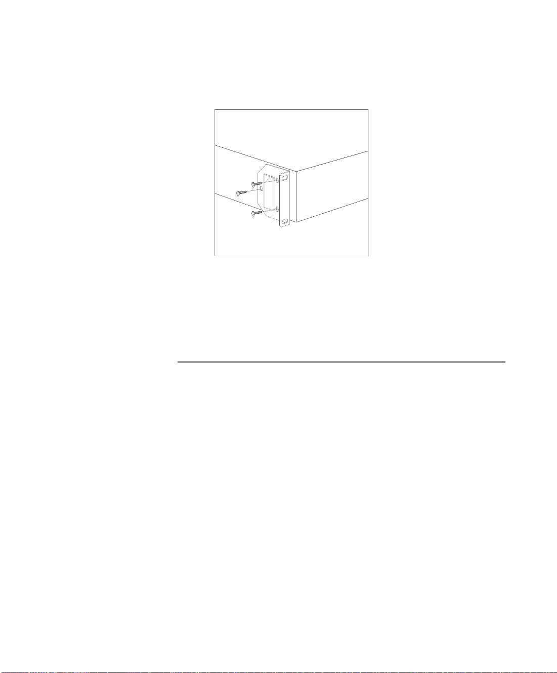
3 Position a mounting bracket over the mounting holes on each
side of the LifeSize Gateway unit, as shown in Figure 2-4.
Setting Up Your LifeSize Gateway 21
Page 30
Mounting the LifeSize Gateway Unit in a 19-inch Rack
Figure 2-4 Fitting a Bracket for Rack Mounting
4
Pass the screws through the brackets and tighten them into the
screw holes on each side of the LifeSize Gateway unit using a
suitable screwdriver.
5 Insert the LifeSize Gateway unit into the 19-inch rack.
6 Fasten the brackets to the side rails of the rack.
7 Make sure that the air vents at the sides of the LifeSize
Gateway unit are not blocked.
22 LifeSize Gateway Installation Guide
Page 31

LifeSize Gateway Unit Initial Configuration
LIFESIZE GATEWAY
UNIT INITIAL
C
ONFIGURATION
Initial monitoring and administration of the LifeSize Gateway unit are
performed from a remote PC via a serial connection. This allows you to access
the boot configuration menu of the LifeSize Gateway unit. At power-up, the
LifeSize Gateway unit goes through the following boot phases:
Auto-boot—The embedded operating system initializes and
displays basic information.
Configuration menu—A 6-second countdown allow s you to enter
the configuration menu.
Initialization—The LifeSize Gateway unit completes its boot
sequence and is ready for operation.
Note You can perform serial port configuration of the LifeSize Gateway unit
only at startup, during a short period indicated by a 6-second countdown. Once the
initialization phase is complete, the only way you can access the configuration
menu is by restarting the LifeSize Gateway unit.
CONNECTING TO A PC This section describes how to use the serial port connection to configure the
LifeSize Gateway unit with an IP address.
Procedure
1 Locate the terminal cable shipped with the LifeSize Gateway
unit.
2 Connect the end labeled PC to the serial port on the computer.
3 Connect the end labeled Unit to the serial port connector on the
LifeSize Gateway unit front panel.
SETTING THE IP ADDRESS
Note The PC terminal should have an installed terminal emulation application,
such as HyperTerminal.
This section describes how to use the serial port to configure the unit with an
IP address and other address information.
The serial port on the LifeSize Gateway unit front panel is used to assign a new
IP address to your LifeSize Gateway unit. You must assign the IP address before
you connect the LifeSize Gateway unit to the network.
Setting Up Your LifeSize Gateway 23
Page 32

LifeSize Gateway Unit Initial Configuration
Before You Begin
Gather the items listed in Table 2-5 to assign an IP address to the LifeSize
Gateway unit.
Table 2-5 Requirements for Setting the IP Address
Requirements Notes
Dedicated IP address for the LifeSize
Gateway
IP address of the default router the LifeSize
Gateway unit uses to communicate over the
network
PC with available serial port and terminal
emulator software installed
RS-232 terminal cable (shipped with the
unit)
unit
Procedure
1 Connect the supplied terminal cable to the PC terminal.
2 Connect the power cable.
3 Start the terminal emulation application on the PC.
4 Set the communication settings in the terminal emulation
5 Turn on the power to the LifeSize Gateway unit.
24 LifeSize Gateway Installation Guide
application on the PC as follows:
Baud rate: 9600
Data bits: 8
Parity: None
Stop bits: 1
Flow control: None
Page 33

LifeSize Gateway Unit Initial Configuration
6 After the terminal emulator session starts, press the RST
button on the LifeSize Gateway unit front panel to reset the
module.
A log of the auto-boot events and a VxWorks banner scrolls
across the computer monitor.
Note When the LifeSize Gateway unit is started for the first time, two
VxWorks banners appear. The configuration option appears after the second
banner.
7 When the message “Press any key to start configuration”
appears on the screen, press any key within 6 seconds.
The network configuration Main menu appears:
Press any Key To start configuration...
Main menu
Enter <N> to configure default network port values
Enter <P> to change the configuration software password
Enter <A> to display advanced configuration menu
Enter <Q> to quit configuration menu and start GW
Caution If you do not press a key before the countdown ends, the device
continues its initialization and you can only configure the device by pressing
the RST button on the front panel.
8 At the prompt, type N to configure default network port values
and press Enter.
9 At the Enter IP address for default interface prompt, type the IP
address you want to assign to the LifeSize Gateway unit and
press Enter.
Caution Do not use leading zeros in the IP address.
Setting Up Your LifeSize Gateway 25
Page 34

LifeSize Gateway Unit Initial Configuration
10 At the Enter Default Router IP Address prompt, type the IP
Caution Do not use leading zeros in the IP address.
11 At the Enter IP Mask <HEX> for default device prompt,
Note You can use the computer’s desktop calculator to convert the subnet
mask ID to hexadecimal notation.
address of the router associated with the segment in which the
unit will be installed and press Enter.
type the subnet mask as follows:
Convert the subnet mask IP address to hexadecimal
notation, type the hexadecimal number at the prompt,
and press Enter.
For example, for the subnet mask 255.255.255.0 the
hexadecimal value you type is FFFFFF00.
12 Allow the unit to complete the reboot process. A new emulator
13 Close the terminal emulator session.
CHANGING THE
C
ONFIGURATION TOOL
OGIN PASSWORD
L
You can use the terminal emulator to change the default password of the default
login user before others can use the LifeSize Gateway interface.
Procedure
1 Start a terminal emulator session for the LifeSize Gateway
2 Press the RST button on the front panel of the LifeSize
26 LifeSize Gateway Installation Guide
If a subnet mask is not used, press Enter.
session begins.
unit.
Gateway unit.
After 60 seconds, a new terminal emulator session begins on the
computer monitor.
Page 35

Connecting the LifeSize Gateway Unit to the LAN
3 After the second VxWorks banner scrolls across the screen, the
following message appears: “Press any Key to start the
configuration.”
4 Press any key and then press Enter.
The default network properties screen appears.
5 At the prompt, enter P and press Enter to select “change the
configuration software password.”
The Enter user name prompt appears.
6 Type the user login name for which you want to change the
password and press Enter.
The default user name is admin. This is the user name that
allows you to access the LifeSize Gateway interface.
The Enter new password prompt appears.
7 Type the password you want the user to use to log in to the
LifeSize Gateway interface and press Enter.
There is no default password.
8 The network configuration Main menu re-appears.
9 Enter Q and press Enter to exit.
CONNECTING THE
L
IFESIZE GATEWAY
U
NIT TO THE LAN
Procedure
This section describes how to connect the LifeSize Gateway uni t to the Local
Area Network (LAN).
1 Connect the supplied LAN cable from your network hub to the
10/100BaseT Ethernet port on the front panel of the LifeSize
Gateway unit. The 10/100BaseT port accepts an RJ-45
connector.
2 Connect a separate ISDN or serial line to each PRI or serial
port in the rear panel of the LifeSize Gateway unit. The port
accepts an RJ-45 connector.
Setting Up Your LifeSize Gateway 27
Page 36

Connecting Serial Lines to the Gateway
CONNECTING
SERIAL LINES TO
THE GATEWAY
Procedure
SERIAL GATEWAY
CABLE
C
ONNECTIONS AND
P
IN-OUTS
You can connect the N/A to four serial lines that may support different physical
standards (V.35, RS-449 or EIA-530). The system is capable of recognizing the
type of cable connected.
1 Connect the DB-60 male connector of the cable to the DB-60
female connector of the unit.
2 Tighten the screws.
3 Connect the remote connectors (V.35, RS-449, EIA-530 and
RS-366) to the connectors or the connecting cable of the
remote equipment
This section describes the DTE cables that you can use with the Gateway-Serial
unit including the following topics:
Physical Description of DTE Cables on page 28 Data Interface Cable Pin-out Configurations on page 34 Data Interface Pin Layouts on page 36 Signaling Interface Cable Pin-out Configuration on page 39 Signaling Interface Pin Layout on page 40
PHYSICAL
ESCRIPTION OF DTE
D
C
ABLES
28 LifeSize Gateway Installation Guide
This section describes the following DTE cables supplied with the
Gateway-Serial unit:
V.35/RS366-DTE on page 29
EIA449/RS366-DTE on page 30
EIA530/RS366-DTE on page 31
Page 37
Serial Gateway Cable Connections and Pin-outs
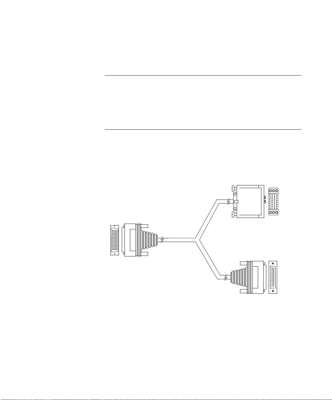
J1 Male (DB-60)
J2 Male
(M-34 Winchester)
J3 Male (DB-25)
V.35 data
RS-366
signaling
EIA530/RS366-DTE- LOS on page 32
KIV7/RS366-DTE on page 33
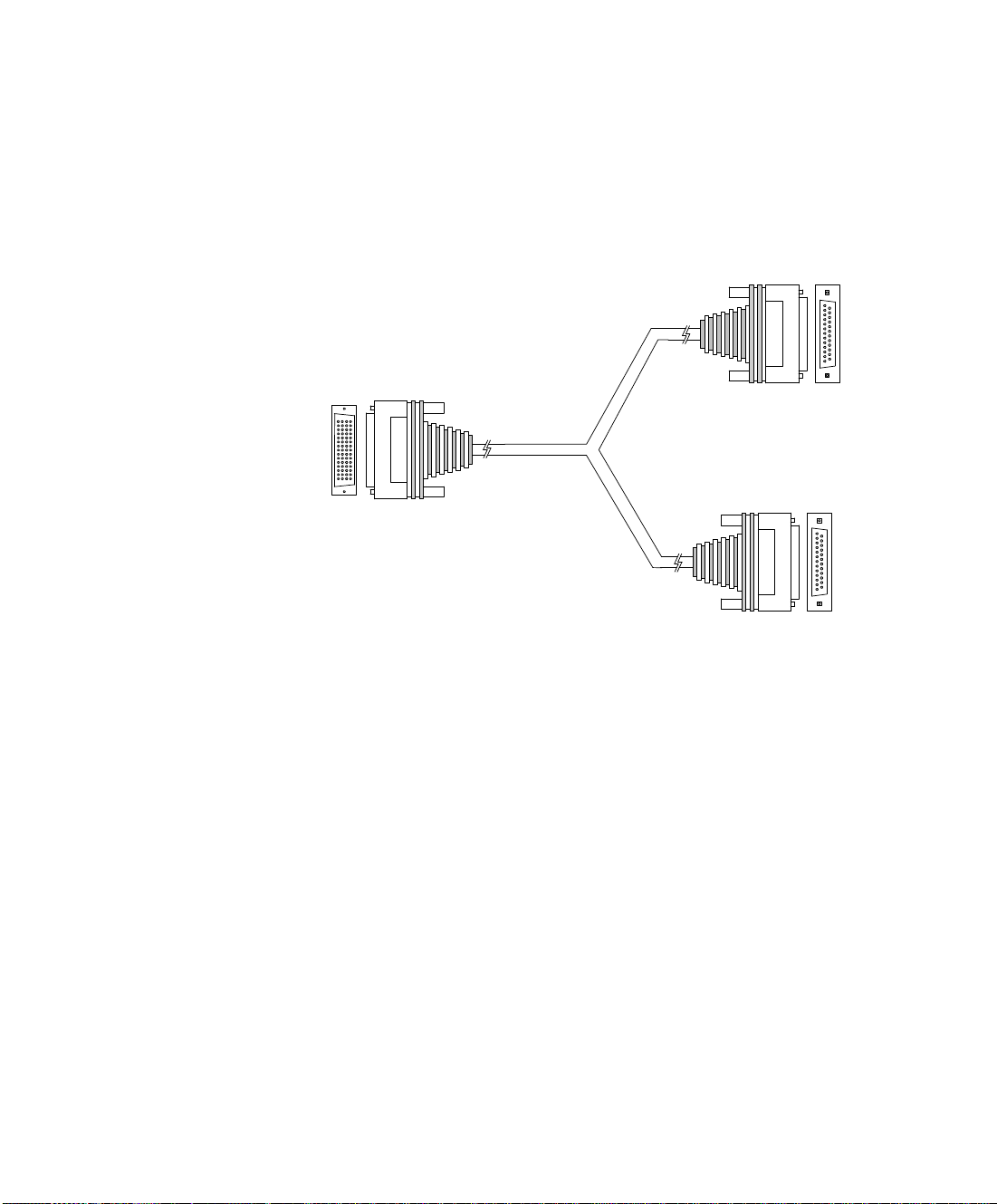
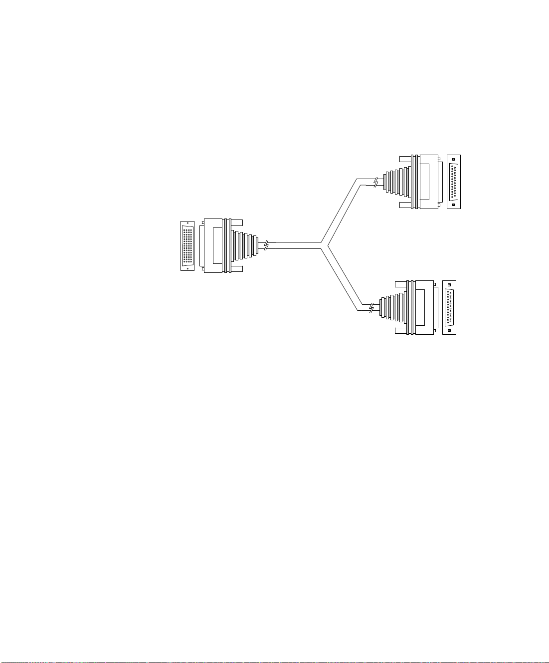
Note The DB-25 connector provides the data interface for the
EIA530/RS366-DTE and EIA530/RS366-DTE- LOS cables.
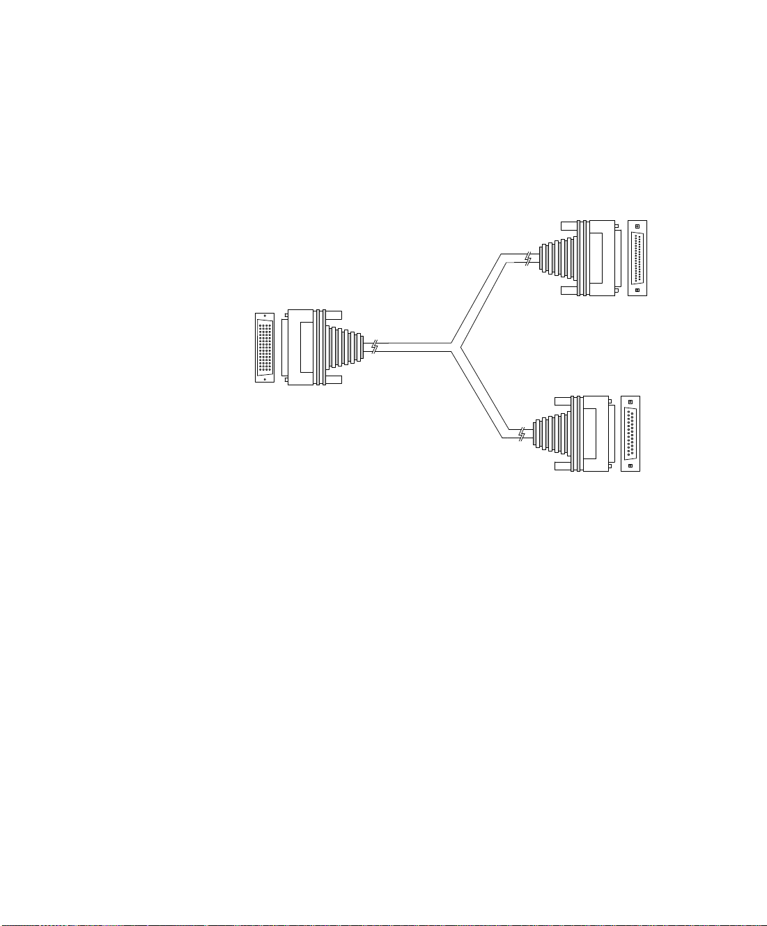
The DB-37 connector provides the data interface for the
EIA449/RS366-DTE and KIV7/RS366-DTE cables.
The DB-25 connector provides the RS-366 signaling interface for all
Gateway-Serial
unit cables.
V.35/RS366-DTE Figure 2-5 shows the V.35/RS366-DTE cable .
Figure 2-5 V.35/RS366-DTE Cable
Setting Up Your LifeSize Gateway 29
Page 38
Serial Gateway Cable Connections and Pin-outs
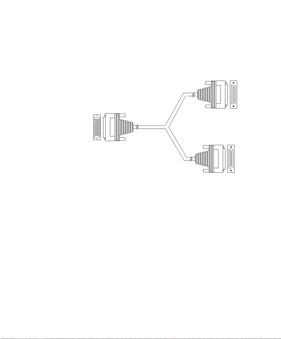
J1 Male (DB-60)
J2 Male (DB-37)
J3 Male (DB-25)
EIA-449 data
RS-366
signaling
EIA449/RS366-DTE Figure 2-6 shows the EIA449/RS366-DTE cable.
Figure 2-6 EIA449/RS366-DTE Cable
30 LifeSize Gateway Installation Guide
Page 39
Serial Gateway Cable Connections and Pin-outs
J1 Male (DB-60)
J3 Male (DB-25)
EIA-530 data
RS-366
signaling
J2 Male (DB-25)
EIA530/RS366-DTE Figure 2-7 shows the EIA530/RS366-DTE cable.
Figure 2-7 EIA530/RS366-DTE Cable
Setting Up Your LifeSize Gateway 31
Page 40
Serial Gateway Cable Connections and Pin-outs
J1 Male (DB-60)
J3 Male (DB-25)
EIA-530 data
RS-366
signaling
J2 Male (DB-25)
EIA530/RS366-DTELOS
Figure 2-8 shows the EIA530/RS366-DTE-LOS cable.
Figure 2-8 EIA530/RS366-DTE-LOS Cable
32 LifeSize Gateway Installation Guide
Page 41
Serial Gateway Cable Connections and Pin-outs
J1 Male (DB-60)
J2 Male (DB-37)
J3 Male (DB-25)
KIV-7 data
RS-366
signaling
KIV7/RS366-DTE Figure 2-9 shows the KIV7/RS366-DTE cable.
Figure 2-9 KIV7/RS366-DTE Cable
Setting Up Your LifeSize Gateway 33
Page 42

Serial Gateway Cable Connections and Pin-outs
DATA INTERFACE
ABLE PIN-OUT
C
CONFIGURATIONS
Table 2-6 describes the data interface pin-out configuration for the
Gateway-Serial cables.
Table 2-6 Serial Gateway Data Interface Cable Pin-out Configuration
Signal Name Mnemonic
DTE only
KIV-7 (DB-37)
Shield — 11111A
Transmit Data TXD A 24222P
Transmit Timing TXC A 15 5 15 15 15 Y
Receive DataRXD A 36333R
Request To SendRTS A 47444C
Receive Timing RXC A 17 8 17 17 17 V
EIA-449 (DB-37)
EIA-530 (DB-25)
DTE only
EIA-530 LOS (DB-25)
DTE only
EIA-530A LOS (DB-25)
V.35 (M-34)
Clear To SendCTS A 59555D
Data Set ReadyDSR A 611666E
Data Terminal
ready
Carrier Detect DCD A 8 13 8 8 8 F
Terminal TimingTT A 2417242424U
Signal Ground — 27 19 7 7 7 B
Transmit DataTXD B 1422141414 S
Transmit TimingTXC B 1223121212AA
Receive DataRXD B 1624161616 T
34 LifeSize Gateway Installation Guide
DTR A 2012202020 H
Page 43

Signal Name Mnemonic
Serial Gateway Cable Connections and Pin-outs
DTE only
KIV-7 (DB-37)
EIA-449 (DB-37)
EIA-530 (DB-25)
DTE only
EIA-530 LOS (DB-25)
DTE only
EIA-530A LOS (DB-25)
V.35 (M-34)
Request To SendRTS B 1925191919—
Receive Timing RXC B 9 26 9 9 9 X
Clear To SendCTS B 1327131313—
Data Set ReadyDSR B 22292222——
Data Terminal
DTR B 23302323——
ready
Carrier DetectDCD B 1031101010—
Terminal Timing TT B 11 35 11 11 11 W
Local LoopbackLL —1018—18L, K
Remote
RLB — 14 21 — 21 N
Loopback
Loss of Sync LOS
3136————
unbalanced
Loss of Sync LOS A — 3 — 18 — —
Loss of Sync LOS B — 21 — 21 — —
Setting Up Your LifeSize Gateway 35
Page 44

Serial Gateway Cable Connections and Pin-outs
J
B
F
L
R
V
Z
DD
JJ
NN
D
N
T
X
BB
FF
LL
A
E
K
P
U
Y
CC
HH
MM
C
H
M
S
W
AA
EE
KK
DATA INTERFACE PIN
AYOUTS
L
M-34 C
ONNECTOR Figure 2-10 shows the M-34 pin assignment.
This section illustrates the pin layouts for the Gateway-Serial cable connectors.
Figure 2-10 M-34 Pin Layout
36 LifeSize Gateway Installation Guide
Page 45

Serial Gateway Cable Connections and Pin-outs
2
1
3
5
7
9
11
13
15
17
19
4
6
8
10
12
14
16
18
20
21
22
23
24
25
26
27
28
29
30
31
32
33
34
35
36
37
DB-37 CONNECTOR Figure 2-11 shows the DB-37 pin layout.
Figure 2-11 D B-3 7 Pin Layout
Setting Up Your LifeSize Gateway 37
Page 46

Serial Gateway Cable Connections and Pin-outs
2
1
3
5
7
9
11
13
4
6
8
10
12
14
15
16
17
18
19
20
21
22
23
24
25
DB-25 CONNECTOR Figure 2-12 shows the DB-25 pin layout.
Figure 2-12 D B-2 5 Pin Layout
38 LifeSize Gateway Installation Guide
Page 47

Serial Gateway Cable Connections and Pin-outs
SIGNALING INTERFACE
ABLE PIN-OUT
C
CONFIGURATION
Table 2-7 describes the signaling interface pin-out configuration for the
Gateway-Serial cables.
Table 2-7 Serial Gateway Signaling Interface Cable Pin-out Configuration
Signal Name Mnemonic RS-366 (DB-25)
Shield — 1
Digit Present DPR 2
Abandon Call & Retry ACR 3
Call Request CRQ 4
Present Next Digit PND 5
Power Indication PWI 6
Signal Ground — 7
Distant Station Connection DSC 13
Digit Signal Circuit 1 NB1 14
Digit Signal Circuit 2 NB2 15
Digit Signal Circuit 4 NB4 16
Digit Signal Circuit 8 NB8 17
Receive Common RC 18
Send Common SC 19
Data Link Occupied DLO 22
Setting Up Your LifeSize Gateway 39
Page 48

Serial Gateway Cable Connections and Pin-outs
2
1
3
5
7
9
11
13
4
6
8
10
12
14
15
16
17
18
19
20
21
22
23
24
25
SIGNALING INTERFACE
IN LAYOUT
P
DB-25 C
ONNECTOR Figure 2-13 shows the DB-25 pin layout.
This section illustrates the pin layout for the Gateway-Serial signaling cable
connector.
Figure 2-13 D B-2 5 Pin Layout
40 LifeSize Gateway Installation Guide
Page 49

Managing and Monitoring the LifeSize Gateway Unit
MANAGING AND
MONITORING THE
L
IFESIZE GATEWAY
U
NIT
You can manage and monitor the LifeSize Gateway unit locally or from remote
connections. You can also upgrade LifeSize Gateway software.
SNMP MANAGEMENT The LifeSize Gateway unit is equipped with an SNMP agent. You can acces s the
LifeSize Gateway unit using an SNMP management client.
LOCAL PORT
ONITORING
M
You should access the LifeSize Gateway unit using a local port connection for
preliminary configuration and monitoring.
CONNECTIONS
S
ERIAL PORT The LifeSize Gateway unit includes a DB-9 serial port connector and an RJ-45
serial port connector. The DB-9 serial port is used to access the boot sequence
menu from a local PC. Using a terminal emulation application running on the
PC, you can assign an IP address and subnet mask to the LifeSize Gateway unit.
The RJ-45 serial port is used to connect a PC terminal to the LifeSize Gateway
unit.
Note A special adapter cable for connecting between a standard DB-9 serial
cable and the RJ-45 serial port is supplied with the LifeSize Gateway unit.
SVGA P
ORT The LifeSize Gateway unit is equipped with an SVGA port for connecting to a
standard PC monitor screen. The SVGA port allows you to view the operating
system desktop and to monitor the applications that are active on the desktop.
PERFORMING
OFTWARE UPGRADES
S
You can perform software upgrades by using the LifeSize Upgrade Utility to
upload files via a network or modem connection to the LifeSize Gateway unit.
For more information, see the Using the LifeSize Software Upgrade Utility
chapter.
Setting Up Your LifeSize Gateway 41
Page 50

Accessing the LifeSize Gateway Administrator Interface
ACCESSING THE
LIFESIZE GATEWAY
A
DMINISTRATOR
I
NTERFACE
The LifeSize Gateway Administrator is a web interface that allows you to
configure general LifeSize Gateway unit settings, monitor LifeSize Gateway
unit operation, create or edit services and perform maintenance.
You access the LifeSize Gateway Administrator web interface in the LifeSize
Gateway unit access window by signing in as an Administrator.
You can use your web browser from any remote PC station to monitor and to
configure the LifeSize Gateway unit. A web server is installed in the LifeSize
Gateway unit
management.
Access to the LifeSize Gateway configuration interface is controlled by a user
name and a password. Once you have entered the settings you want, you should
upload them to the unit for them to take effect, or you can save them to a
configuration file to be loaded at a later time.
Before You Begin
The following requirements are necessary to access the Gateway Administrator
web interface:
A Java-compliant browser. Microsoft Internet Explorer version 5.5 or
The LifeSize Gateway unit IP address or a web link to the LifeSize
Administrator level-access
The required user name and password.
to facilitate the use of the remote web-based monitoring and
later is recommended.
Gateway unit.
Note For first-time installation, you must assign an IP address to the LifeSize
Gateway unit using a serial port connection before you can access the web
interface. For more information, see Setting the IP Address on page 23.
Procedure
1 Launch your browser and type the IP address or the name of
42 LifeSize Gateway Installation Guide
the LifeSize Gateway unit.
For example, http://125.221.23.44 or board_name.
The LifeSize Gateway login page appears.
Page 51

Registering the Online Help
2 Type the Administrator user name and password in the
appropriate fields and click Login. The default global user
name is admin. The default password is <null>.
The Gateway Administrator interface appears.
Note If you try to sign in as an Administrator and another Administrator is
currently signed in, the LifeSize Gateway signs you in as a Read only user and
the words Read Only appear at the top of the window. Read only users cannot edit
any of the LifeSize Gateway settings.
REGISTERING THE
O
NLINE HELP
Procedure
The LifeSize Gateway is equipped with online help that is linked to the LifeSize
Gateway Administrator web interface. The help library is stored on the LifeSize
web site.
The Online Help folder available from the LifeSize Gateway CD-ROM included
in the product box contains the online help library. If you wish to install the
online help on a shared network location and link it to the LifeSize Gateway
Administrator, perform the following steps:
1 Copy the Online Help folder from the LifeSize Gateway
CD-ROM to a shared folder on a PC on your network. For
example:
\\myComputer\LifeSize Gateway\Online Help
2 Log in to the LifeSize Gateway Administrator interface.
3 In the Online help URL field of the Device Web tab, type the
directory path to the help files you installed on your PC.
The path must have the form:
file://computerName/sharedDirectory
where computerName is the name of the computer on the
network and
folder on the CD-ROM. For example:
file://myComputer/LifeSize Gateway/Online Help
sharedDirectory is the path to the Online Help
Setting Up Your LifeSize Gateway 43
Page 52

Registering the Online Help
4 Click Upload in the LifeSize Gateway Administrator toolbar,
followed by Refresh.
5 You may need to log out and log back in to the LifeSize
Gateway Administrator for the change to take effect.
44 LifeSize Gateway Installation Guide
Page 53

3
USING THE LIFESIZE SOFTWARE UPGRADE UTILITY
This section describes the LifeSize Software Upgrade Utility, and includes the
following topics:
Introduction Launching the Utility Upgrading Software
INTRODUCTION The LifeSize Software Upgrade Utility is an interactive GUI interface that
enables you to upgrade LifeSize software installed on LifeSize Gateways.
The LifeSize Software Upgrade Utility enables you to select files to be uploaded
via a network or modem connection to the LifeSize Gateway. You can select
either to perform a typical upgrade which includes all the new files or a
customized upgrade which enables you to select which files to upload.
The upgrade files are uploaded and then burned into the memory of the LifeSize
Gateway.
Before You Begin
LifeSize Gateways automatically save configuration settings before a software
upgrade takes place. However, it is recommended that you save all configuration
information using the Export button in the LifeSize Gateway web interface
toolbar. You can retrieve all these settings after the software upgrade is complete
by using the Import button in the LifeSize Gateway web interface toolbar.
Using the LifeSize Software Upgrade Utility 45
Page 54

Launching the Utility
LAUNCHING THE
UTILITY
Procedure
UPGRADING
S
OFTWARE
Procedure
This section describes how to install and launch the LifeSize Software Upgrade
Utility.
1 Download the UpgradeUtility.exe file from the LifeSize web
site at www.lifesize.com/service
2 Double click the UpgradeUtility.exe file to run the Software
Upgrade Utility.
The upgrade files are extracted and the Upgrade Utility dialog
box appears.
This section describes how to use the Software Upgrade Utility to upgrade
LifeSize software installed on LifeSize Gateways.
1 In the General Information section of the Upgrade Utility
dialog box, enter the IP address of the LifeSize Gateway you
want to upgrade.
2 In the Login Information section, enter the administrator user
name and password for the target LifeSize Gateway, as
configured in the LifeSize Gateway network configuration
settings.
3 (Optional) Modify the read and write community settings for
the target LifeSize Gateway as follows:
Click Customize SNMP Settings.
The Customize SNMP Settings dialog box displays.
Enter the required read community and write
community values.
.
Note We recommend that you modify the default setting s for securi ty
purposes.
46 LifeSize Gateway Installation Guide
Page 55

Upgrading Software
Click OK to r eturn to the Upgrade Utility dialog box.
4 (Optional) Select the components of the target LifeSize
Gateway you want to upgrade as follows:
Click Customize.
The Customize dialog box appears.
Check the LifeSize Gateway components you want to
upgrade in the Select the components you want to
upgrade list.
Click OK to r eturn to the Upgrade Utility dialog box.
5 Click Upgrade to upgrade all components of the LifeSize
Gateway software (or only those components you manually
selected via the Customize option).
The LifeSize Software Upgrade Utility informs you whether or
not the upgrade is successful.
Note When the upgrade is complete, the LifeSize Gateway automatically
resets itself and starts operation with the new software version.
Using the LifeSize Software Upgrade Utility 47
Page 56

Upgrading Software
48 LifeSize Gateway Installation Guide
Page 57

4
CABLE CONNECTIONS AND PIN-OUTS
This section describes the pin-to-pin and pin-out configurations of the
connectors and cables of the LifeSize Gateway unit, including the following
topics:
Unit RS-232 9-Pin Serial Port
RJ-45 8-Pin IP Network Port
RJ-45 Serial Port Adapter Cable
Cable Connections and Pin-outs 49
Page 58

Unit RS-232 9-Pin Serial Port
UNIT RS-232 9-PIN
SERIAL PORT
RJ-45 8-PIN IP NETWORK PORT
Table 4-1 describes the LifeSize Gateway unit RS-232 9-pin D-type serial port
pin-out configuration.
Table 4-1 RS-232 9-pin D-Type Serial Port Pin-out
Pin Function I/O
1NC
2 RXD Input
3 TXD Output
4NC
5 GND
6NC
7NC
8NC
9NC
Table 4-2 describes the pin-out configuration of the RJ-45 IP network port.
Table 4-2 Pin-out Configuration of the RJ-45 IP Network Port
Pin Function I/O
1 TXD+ Output
2 TXD+ Output
3 RXD+ Input
4NC
5NC
6 RXD- Input
7NC
8NC
50 LifeSize Gateway Installation Guide
Page 59

RJ-45 Serial Port Adapter Cable
RJ-45 SERIAL
PORT ADAPTER
C
ABLE
Table 4-3 describes the pin-to-pin configuration of the RJ-45 to DB-9 adapter
cable used to connect a PC terminal to the RJ-45 serial port. This cable is
provided with the LifeSize Gateway unit.
Table 4-3 Pin-to-Pin Configuration of the RJ-45 to DB-9 Adapter Cable
RJ-45 (Male) DB-9 (Female) Function
1NC
2NC
33 TXD
4NC
5 5 GND
62 RXD
7NC
8NC
ISDN PORT Table 4-4 describes the ISDN Port RJ-45 connector pin-out configuration.
Table 4-4 ISDN Port RJ-45 Connector Pin-out
Pin Function
1 RXD +
2 RXD 3NC
4 TXD +
5 TXD 6NC
7NC
8NC
Cable Connections and Pin-outs 51
Page 60

ISDN Port
52 LifeSize Gateway Installation Guide
Page 61

5
TECHNICAL SPECIFICATIONS
This section provides technical specifications for the LifeSize Gateway.
TECHNICAL
S
PECIFICATIONS
T
ABLE
Table 5-1 LifeSize Gateway Unit Technical Specifications
Unit Dimensions Height: 1U (1.75 inches or 44.45 mm)
Width: 17.25 inches (438.15 mm)
Depth: 10 inches (254 mm)
Weight: 4.45 kg (9.81 lbs)—may vary according
to configuration
LED Indicators
Front panel ETHERNET:
Link
Connection Speed
GK
D-Ch
ALRM
ACT
Rear panel (Gateway-PRI)
Rear panel (N/A)
ACT
D-Ch
ALRM
ACT 1 to 4
Technical Specifications 53
Page 62

Technical Specifications Table
Table 5-1 LifeSize Gateway Unit Technical Specifications (continued)
Rear panel
(Gateway-Serial)
ACT 1 to 4
ALRM 1 to 4
Push Buttons RST (front panel)
Communication Interfaces
Front panel Ethernet 10/100 Mbps auto-negotiate speed select
Asynchronous serial port RS-232 connected via
9-pin D-type connector
RJ-45 serial port (for video processing module)
SVGA port (for video processing module)
USB connector (for video processing module)
Rear panel (Gateway-PRI)
2 x ISDN E1/T1 PRI port:
T1 mode
Channels: 23B + 1D
Clock rate: 1.544 Mbps
Framing: F4, F12, ESF no CRC, ESF, F72
Encoding: NRZ, AMI-B7, B8ZS
Line impedance: 100Ω
E1 mode
Channels: 30B + 1D
Clock rate: 2.048 Mbps
Framing: Double framing, CRC4, Extended
CRC4
Encoding: NRZ, CMI, AMI, HDB3
Line impedance: 120Ω
Rear panel
(Gateway-Serial)
Chipset PowerPC MPC755 32-bit RISC microprocessor
Operating System RTOS, VxWorks 5.4
54 LifeSize Gateway Installation Guide
4 x serial ports
running at 400MHz or more
MPC8260 secondary microprocessor running at
200/133MHz or more
Page 63

Technical Specifications Table
Table 5-1 LifeSize Gateway Unit Technical Specifications (continued)
Memory 32 MB on-board flash memory for field upgrades,
supports up to 64 MB
1 MB L-2 Cache at 200 MHz or more
128 MB SDRAM, supports up to 256 MB
Failsafe Watchdog timer built in
Power Supply Input 100-240VAC autoswitched
Output + 3.3VDC, + 5VDC, + 12VDC
Maximum power load 150W
Technical Specifications 55
Page 64

Technical Specifications Table
56 LifeSize Gateway Installation Guide
Page 65

INDEX
A
access control 3
ACT LED 18, 19, 20
Administrator interface 42
ALRM LED 18, 19, 20
audio codecs 5
audio transcoding 5
auto-boot 22
B
bandwidth
call overhead 15
resource allocation 16
supported 6
bonding
calls 8
boot configuration menu 22
C
cables
DCE 28
DTE 28
EIA449/RS366-DTE 30
EIA530/RS366-DTE 31
EIA530/RS366-DTE-LOS 32, 33
KIV7/RS366-DTE 33
RJ-45 8-pin IP network port 50
RJ-45 serial port adapter 51
RS-232 9-pin serial port 50
V.35/RS366-DTE 29
call bandwidth overhead 15
call handling
capabilities 7
PRI gateway capacity 15
chipset 54
communication interfaces 54
conceal caller ID 4
connectors
Ethernet 18
PORT 20
PRI line 19
serial port 18, 41
D
data collaboration 2
DB-60 20
DB-9 7, 18, 41
D-Ch LED 19
default extension 3
diagnostics 2
dial plan 3
DID 3
direct dialing 3
downspeeding 4
DTE 28
DTMF 3
dual video 3
E
E1/T1 11, 16
EIA-530 28
encryption 5
interoperability 8
serial gateway 13
Index 57
Page 66

via satellite 13
Ethernet
10/100Base-T 7
connector 18
Ethernet LED 18
F
failsafe 55
fast start 4
feature summary
general features 2
first-time installation 42
front panel 18
G
GK LED 18
H
H.239 5
H.243 5
H.323
fast start 4
serial gateway 14
LED indicators 18, 19, 20, 53
line quality 7
local
configuration 41
monitoring 41
M
media + signaling combinations 7
media protocols 7
memory 55
MSN 3
multimedia conferencing 9
multipoint conferencing 10
N
network load balancing 2
Network Specific Facility (NSF) 4
O
online help 43
operating system 54
I
initial configuration 22
installation requirements 20
interoperability 2
IP address assign 24
IP network connection 5, 7
ISDN
connection failure 4
rollover 4
IVR 3
internal capacity 8
L
LAN 18, 27
10/100Base-T 7
leased lines
58 LifeSize Gateway Installation Guide
P
package contents 21
password
default login user 26
peer-to-peer
connectivity 5, 16
physical description
gateway 18
pin layout
DB-25 38, 40
DB-37 37
M-34 36
serial gateway cable connectors 36
serial gateway signaling cable connector
40
pin-out configuration
RJ-45 IP network port 50
Page 67

RS-232 9-pin D-type serial port 50
serial gateway data interface cable 34
serial gateway signaling interface cable 39
pin-to-pin configuration
RJ-45 to DB-9 adapter cable 51
point-to-point conferencing 10
PORT connectors 20
ports
IRJ-45 8-pin ISDN 51
RJ-45 IP 50
RJ-45 serial 51
RS-232 9-pin serial 50
supported 5
SVGA 41
power supply 55
PRI
call handling capacity 15
connecting gateway directly to central office
switch 12
connecting gateway to a PBX 12
interface features 8
ISDN connections 11
PRI LINE connectors 19
push buttons 54
Q
Q.931 3
Quality of Service (QoS) 2
R
rack mounting 21
rear panel 19, 20
remote
management 41
requirements 24
installation 20
RJ-45 18, 19, 41
rollover 4
routing 3
RS-232
DTE 9-pin D-type connection 7
RS-449 28
RST button 18, 54
S
serial control port 7
serial lines 28
serial port connector 18, 41
DB-9 41
setup procedures
access Administrator interface 42
change default password 26
connect a serial cable 28
connect to a PC 23
connect unit to LAN 27
mount unit on a 19-inch rack 21
set IP address 24
signaling protocols 7
SNMP
management 2, 41
trap servers 4
software upgrade utility procedures
install and launch 46
use utility 46
software upgrades 41
SVGA 41
switch information 8
T
T.120
data collaboration 2
TCS4 3
U
unit dimensions 53
upgrade software 45
V
V.35 28
video conferencing protocols 5
video protocols 6
Index 59
Page 68

video resolutions 6
W
web-based management 2
60 LifeSize Gateway Installation Guide
 Loading...