

Page 1
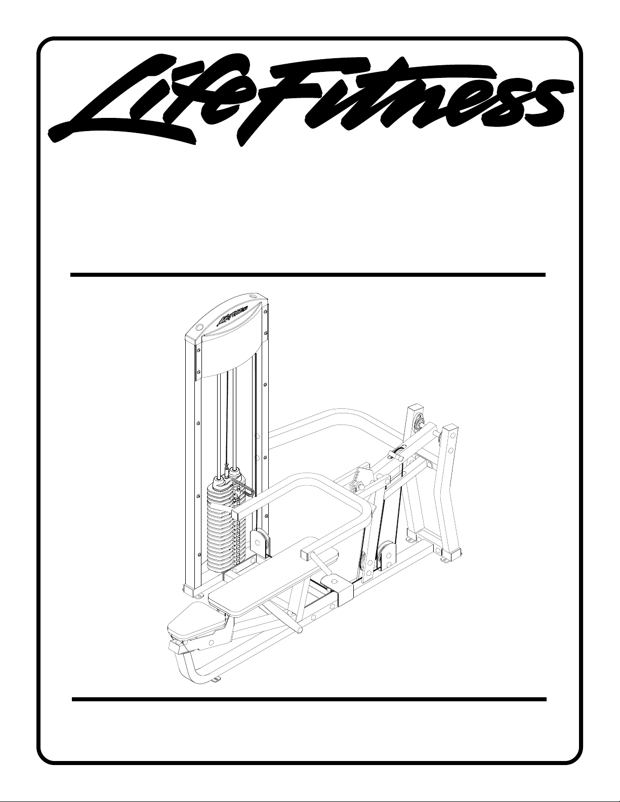
FIT SERIES
MULTI PRESS
Part # 7489101
Rev B-3.
ASSEMBLY INSTRUCTIONS
Revision: 10/17/061
Page 2
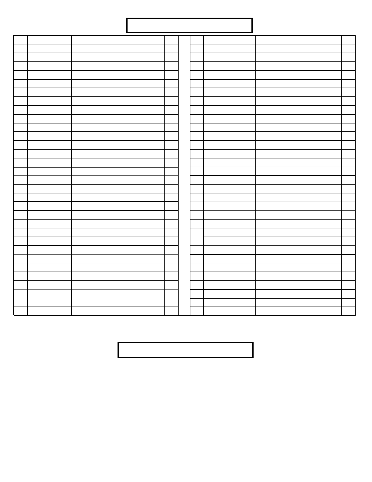
PARTS LIST
Hardware Bag
ACUHB-FSMPPLAT -or- ACUHB-FSMPWHT
KEY
ACU04-1647
1
ACU02-0078
2
ACU04-1361
3
ACU04-1338
4
ACU04-1643
5
ACU04-1358
6
ACU04-1362
7
ACU04-1642
8
ACU04-1639
9
ACU04-1385
10
ACU02-1294
11
ACU01-2028
12
ACU04-1646
13
ACU04-1645
14
ACU04-1644
15
ACU07-0156
16
ACU07-0158
17
ACU05-0351
18
ACU06-0025
19
ACU06-0304
20
ACU01-2387
21
22
23
24
25
26
27
28
29
30
31
ACU79352
ACU02-1304
ACUAAP10-0053
ACUP11-0048
ACU05-0212
ACU05-0348
ACU03-0536
ACU06-0371
ACU05-0356
ACU08-0085
PART #
DESCRIPTION
TOWER
3-1/2 X 1” CABLE CLIP
SEAT PAD SUPPORT
PRESS ARM
PIVOT ARM
MULTI PRESS SEAT ADJUST
BACK PAD SUPPORT
PRESS FRAME
GUIDE ROD SUPPORT
PRESS ARM ADJUST PLATE
MULTI PRESS ADJUST PLATE
MULTI PRESS SLIDE TUBE
BASE
UPPER SUPPORT
REAR UPRIGHT
BACK PAD
SEAT PAD
PILLOW BLOCK
4-1/2” PULLEY
3/4 X 2” WEIGHT STACK CUSHION
GUIDE ROD
WEIGHT PLATE
2-7/8” X 2-1/4” CABLE CLIP
HEAD PLATE ASSY
WEIGHT STACK PIN
13/16” SHAFT COLLAR
5-1/2” PIVOT SHAFT
5-1/2” TAPPED SHAFT
ACCORDIAN SLEEVE
PILLOW BLOCK SPACER
3/8 X 1/2” FLANGE SPACER
QTY
1
1
1
1
1
1
1
1
1
1
2
1
1
1
1
1
1
2
7
2
2
20
1
1
1
2
2
1
2
4
8
KEY
32
33
34
35
36
37
38
39
40
41
42
43
44
45
46
47
48
49
50
51
52
53
OR
54
55
56
57
58
59
60
PART #
ACU08-0078
ACU08-0077
ACUDA1C03802516NU
ACUDA1C03803216NU
ACUDA1C03804316NU
ACUDA1C03804316YU
ACUDA1C03806116NU
ACUDA1C03806716NU
ACUDA1C03807016NU
ACUDA1C03807316NU
ACUDA1C03809016NU
ACUDA1C03810616NU
ACUDA1C03816416NU
ACUDAEC03802516YB
ACUDAEC03807616NB
ACUDAEC03809016NB
ACUDC1250100020B
ACUDB2E03807200U
ACUDC120010510U
ACU05-0310
ACU06-0357
ACU06-0357
ACU06-0357
ACUP13-0124
ACUMD000132
ACUAP06-0257
ACU10-0227
ACUA10-0230
ACUDB9E03813016B
ACUDC1250100020U
DESCRIPTION
3/8 X 3/4” FLANGE SPACER
3/8 X 1” FLANGE SPACER
3/8 X 25mm BOLT
3/8 X 32mm BOLT
3/8 X 43mm BOLT
3/8 X 43mm BOLT W/LOCTITE
3/8 X 61mm BOLT
3/8 X 67mm BOLT
3/8 X 70mm BOLT
3/8 X 73mm BOLT
3/8 X 90mm BOLT
3/8 X 106mm BOLT
3/8 X 164mm BOLT
3/8 X 25mm BUTTON HEAD BOLT
3/8X76mm BUTTONHEAD BOLT
3/8X90mm BUTTONHEAD BOLT
3/8” BLACK FLAT WASHER
3/8” LOW HEIGHT LOCK NUT
3/8” SAE WASHER
3/8” RH WASHER
BLACK RH CAP
WHITE RH CAP
PLATINUM RH CAP
MULTI PRESS CABLE
WEIGHT STACK LABEL
TOWER CAP
FRONT SHROUD
REAR SHROUD
3/8” ACORN NUT
3/8” FLAT WASHER
QTY
1
1
1
2
4
2
2
14
1
3
7
2
2
2
4
10
26
37
69
69
17
52
52
1
1
1
1
1
10
4
Tools Required for Assembly
* 9/16” wrench
* Ratchet with 9/16” socket
* Metric Allen wrench set
2
Page 3
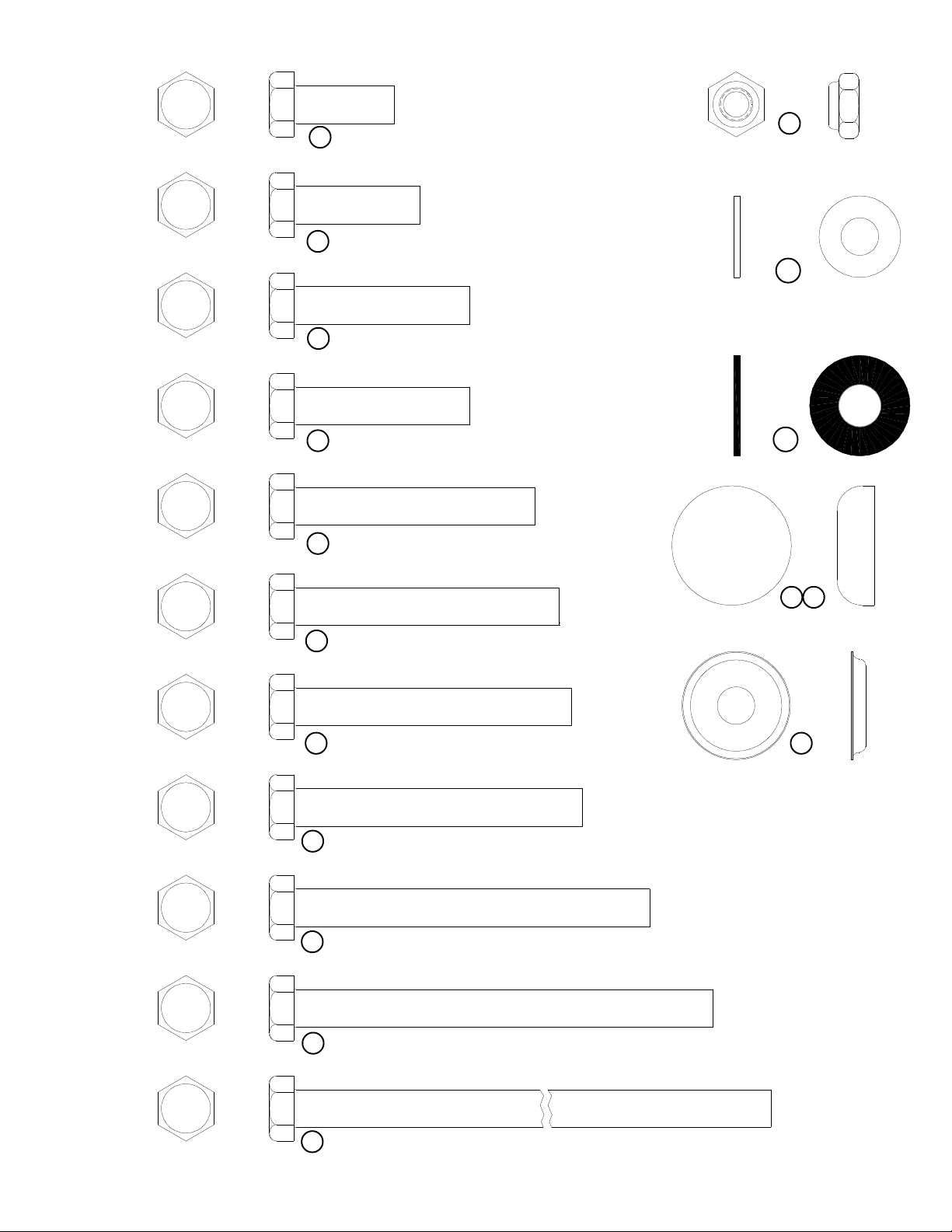
34 3/8 X 25mm BOLT
35 3/8 X 32mm BOLT
36 3/8 X 43mm BOLT
49
3/8” LOW
HEIGHT LOCK
NUT
50
3/8” SAE
WASHER
37 3/8 X 43mm BOLT W/NYLOCK
38 3/8 X 61mm BOLT
39 3/8 X 67mm BOLT
40 3/8 X 70mm BOLT
41 3/8 X 73mm BOLT
48
3/8” BLACK
FLAT WASHER
52
53
RH CAP
(WHITE/PLATINUM/BLACK)
51
RH
WASHER
42 3/8 X 90mm BOLT
43 3/8 X 106mm BOLT
44 3/8 X 164mm BOLT
3
Page 4
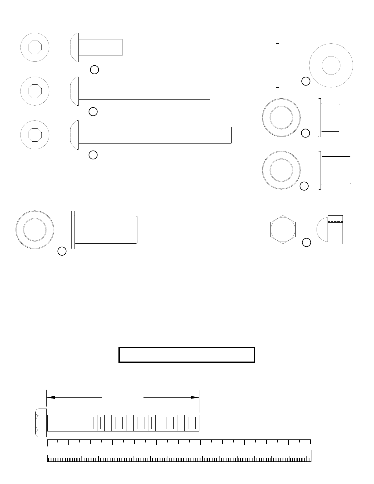
33
BOLT LENGTH
3/8 X 1”
FLANGE SPACER
45 3/8 X 25mm BUTTON HEAD BOLT
60
3/8”
FLAT WASHER
46 3/8 X 76mm BUTTON HEAD BOLT
31
3/8 X 1/2” FLANGE SPACER
47 3/8 X 90mm BUTTON HEAD BOLT
32
3/8 X 3/4”
FLANGE SPACER
59
3/8”
ACORN NUT
Bolt Length Ruler
NOTE: BOLT LENGTH IS MEASURED FROM THE UNDERSIDE OF THE HEAD OF THE BOLT.
0
1/2
10 20 30 40 50 60 70 80 90 100 110 120 130 140 150
1
1/2 1/2 1/2 1/2 1/2
2 3 4 5 6
4
Page 5
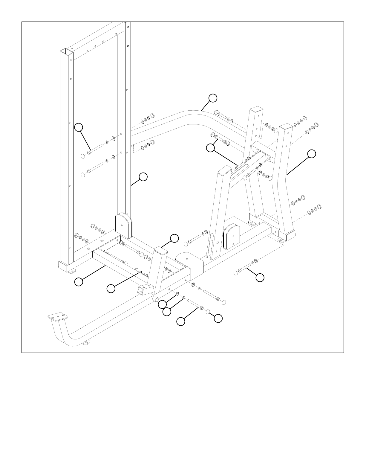
39 3/8 X 67mm
14
13
49
1
51
50
3/8 X 90mm 42
3/8 X 67mm 39
15
8
42 3/8 X 90mm
53
FIGURE 1
STEP 1:
• LOOSELY assemble the BASE (13) to the PRESS FRAME (8) and TOWER (1) using eight RH CAPS (53), four 3/8 X 90mm BOLTS
(42), eight 3/8” SAE WASHERS (50), eight 3/8” RH WASHERS (51) and four 3/8” LOW HEIGHT LOCK NUTS (49) as shown in FIGURE 1.
• LOOSELY assemble the REAR UPRIGHT (15) to the PRESS FRAME (8) and using eight RH CAPS (53), two 3/8 X 90mm BOLTS (42), two
3/8 X 67mm BOLTS (39), eight 3/8” SAE WASHERS (50), eight 3/8” RH WASHERS (51) and four 3/8” LOW HEIGHT LOCK NUTS (49)
as shown in FIGURE 1.
• LOOSELY assemble the UPPER SUPPORT (14) to the REAR UPRIGHT (15) and the TOWER (1) and using eight RH CAPS (53), four 3/
8 X 67mm BOLTS (39), eight 3/8” SAE WASHERS (50), eight 3/8” RH WASHERS (51) and four 3/8” LOW HEIGHT LOCK NUTS (49)
as shown in FIGURE 1.
5
Page 6
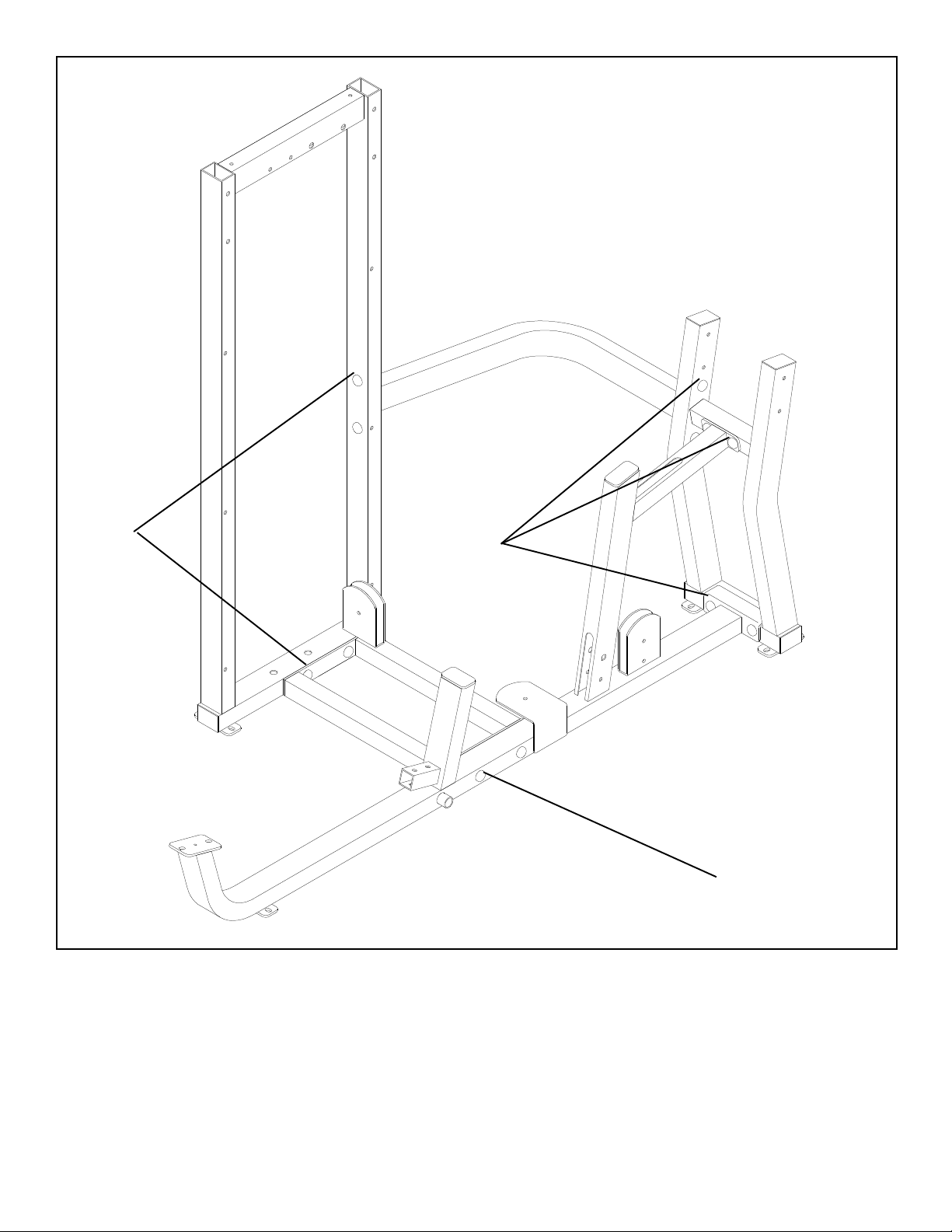
TIGHTEN!
FIGURE 2
STEP 2:
TIGHTEN!
TIGHTEN!
• Securely tighten all loose frame connections made to this point, then proceed to snap RH CAPS
(53) over the RH WASHERS (51) on all tightened connections.
6
Page 7
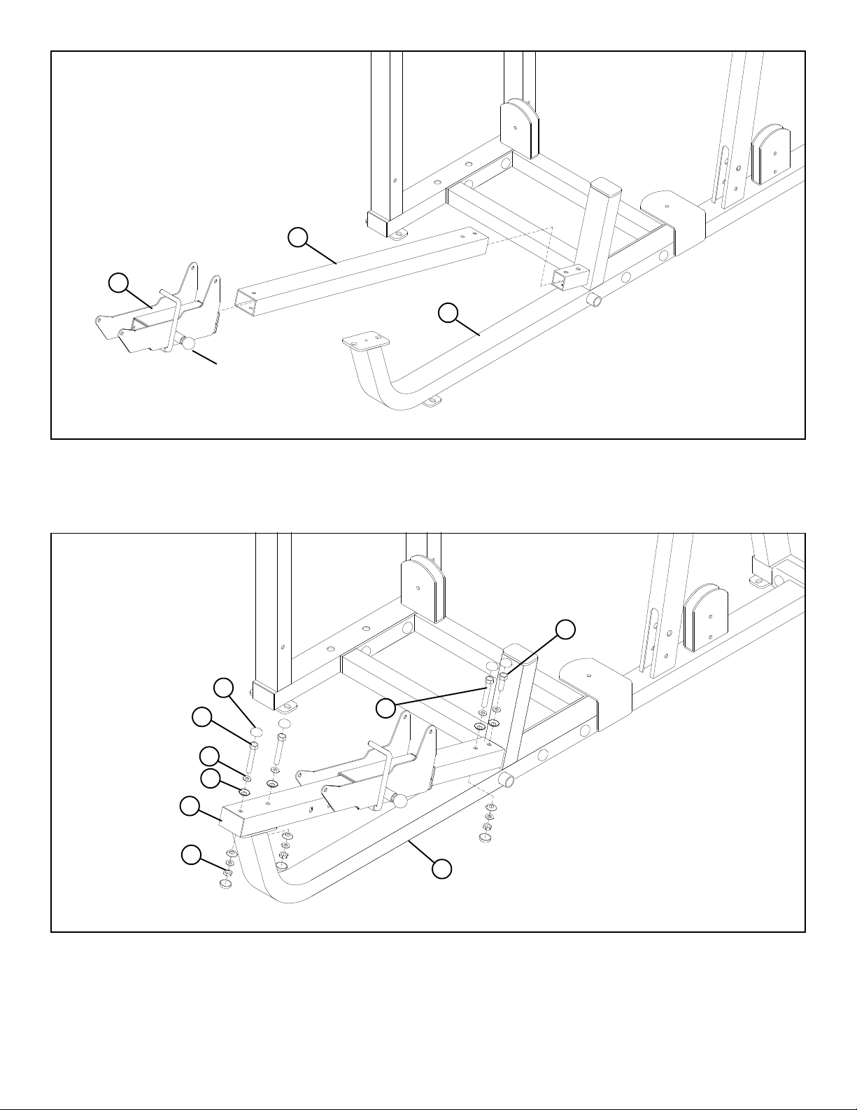
12
6
8
SPRING PIN
FIGURE 3
STEP 3:
• Pull back on the SPRING PIN and slide the SEAT ADJUST (6) over the SLIDE TUBE (12) as shown in FIGURE 3.
• Assemble the SLIDE TUBE (12) to the PRESS FRAME (8) as shown in FIGURE 3.
34 3/8 X 25mm
53
3/8 X 67mm 39
50
51
12
49
3/8 X 61mm 38
8
FIGURE 4
STEP 4:
• SECURELY assemble the SLIDE TUBE (12) to the PRESS FRAME (8) using seven RH CAPS (53), two 3/8 X 67mm BOLTS (39), one
3/8 X 61mm BOLT (38), one 3/8 X 25mm BOLT (34), seven 3/8” SAE WASHERS (50), seven 3/8” RH WASHERS (51) and three 3/8”
LOW HEIGHT LOCK NUTS (49) as shown in FIGURE 4.
7
Page 8
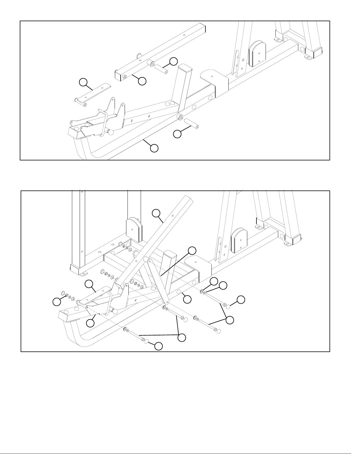
27
3
7
27
8
FIGURE 5
STEP 5:
• Insert one 5-1/2” PIVOT SHAFT (27) into the PRESS FRAME (8) and one 5-1/2” PIVOT SHAFT (27) into the BACK PAD SUPPORT (7)
as shown in FIGURE 5.
7
11
51
50
44 3/8 X 164mm
52 BLACK
FIGURE 6
49
3
8
6
43 3/8 X 106mm
52 BLACK
STEP 6:
• SECURELY assemble the BACK PAD SUPPORT (7) to the SEAT ADJUST (6) using two BLACK RH CAPS (52), one 3/8 X 106mm BOLT
(43), two 3/8” SAE WASHERS (50), two 3/8” RH WASHERS (51) and one 3/8” LOW HEIGHT LOCK NUT (49) as shown in FIGURE 6.
(NOTE: Tighten connections enough to remove slop, yet allow part to rotate freely.)
• SECURELY assemble two MULTI PRESS ADJUST PLATES (11) to the BACK PAD SUPPORT (7) and to the PRESS FRAME (8) using
four BLACK RH CAPS (52), two 3/8 X 164mm BOLTS (44), four 3/8” SAE WASHERS (50), four 3/8” RH WASHERS (51) and two 3/8”
LOW HEIGHT LOCK NUTS (49) as shown in FIGURE 6.
• SECURELY assemble the SEAT PAD SUPPORT (3) to the SEAT ADJUST (6) using two BLACK RH CAPS (52), one 3/8 X 106mm BOLT
(43), two 3/8” SAE WASHERS (50), two 3/8” RH WASHERS (51) and one 3/8” LOW HEIGHT LOCK NUT (49) as shown in FIGURE 6.
(NOTE: Tighten connections enough to remove slop, yet allow part to rotate freely.)
8
Page 9
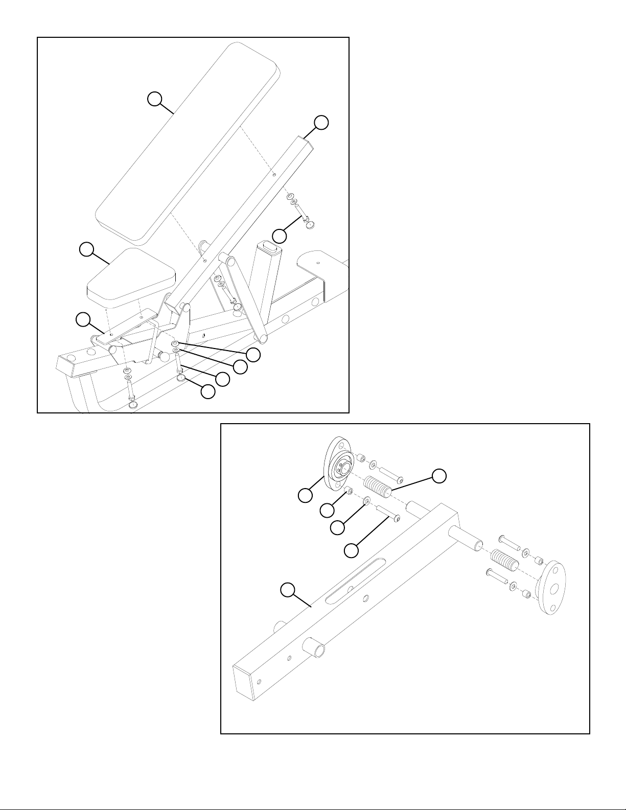
FIGURE 7
17
3
16
STEP 7:
• SECURELY assemble the BACK PAD (16) to the BACK
PAD SUPPORT (7) using two BLACK RH CAPS (52),
two 3/8 X 73mm BOLTS (41), two 3/8” SAE WASHERS
(50) and two 3/8” RH WASHERS (51) as shown in FIGURE 7.
7
• SECURELY assemble theSEAT PAD (17) to the SEAT
PAD SUPPORT (3) using two BLACK RH CAPS (52),
two 3/8 X 32mm BOLTS (35), two 3/8” SAE WASHERS
(50) and two 3/8” RH WASHERS (51) as shown in FIGURE 7.
41 3/8 X 73mm
52
BLACK
STEP 8:
• Slide two ACCORIDIAN SLEEVES (29)
over the shafts of the PIVOT ARM (5) as
shown in FIGURE 8.
• Slide two PILLOW BLOCKS (18) over the
shafts of the PIVOT ARM (5) as shown
in FIGURE 8.
• Assemble four 3/8 X 76mm BUTTON
HEAD BOLTS (46), four 3/8” BLACK
FLAT WASHERS (48) and four PILLOW BLOCK SPACERS (30) to the the
PILLOW BLOCKS (18)
FIGURE 8.
as shown in
51
50
35 3/8 X 32mm
29
18
30
BLACK 48
3/8 X 76mm 46
BUTTON HEAD
5
FIGURE 8
9
Page 10
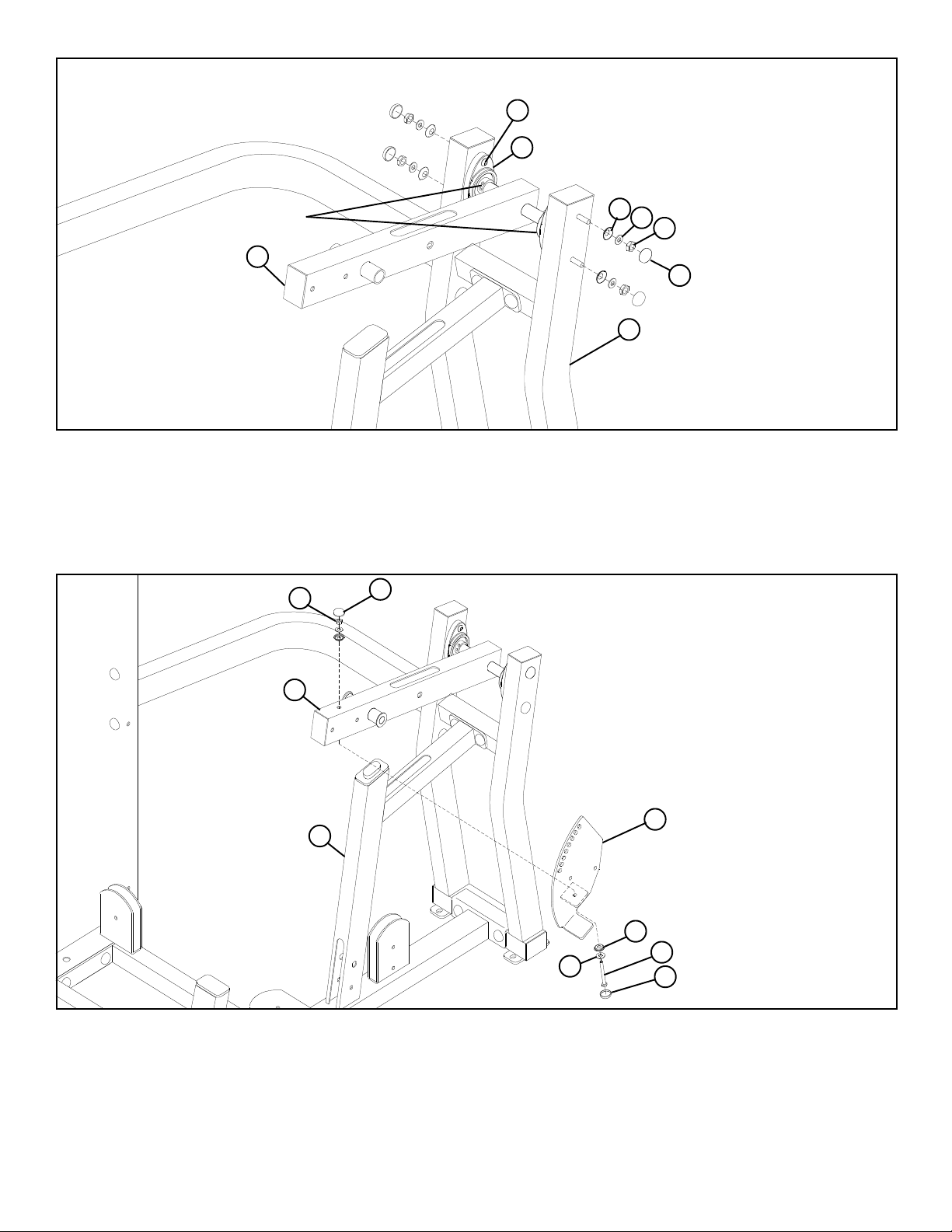
46
18
51
15
50
49
53
TIGHTEN!
5
FIGURE 9
STEP 9:
• SECURELY assemble the PIVOT ARM (5) to the REAR UPRIGHT (15) using four previously inserted 3/8 X 76mm BUTTON HEAD
BOLTS (46), four RH WASHERS (51), four 3/8” SAE WASHERS (50), four 3/8” LOW HEIGHT LOCK NUTS (49) and four RH CAPS
(53) as shown in FIGURE 9.
• IMPORTANT! When PIVOT ARM (5) is centered and level in the PILLOW BLOCKS (18), tighten the PILLOW BLOCK set screws.
49
5
8
53
50
10
51
42 3/8 X 90mm
52 BLACK
FIGURE 10
STEP 10:
• LOOSELY assemble the PRESS ARM ADJUST PLATE (10) to the PIVOT ARM (5) using one RH CAP (53), one BLACK RH CAP
(52), one 3/8 X 90mm BOLT (42), two 3/8” SAE WASHERS (50), two 3/8” RH WASHERS (51) and one 3/8” LOW HEIGHT LOCK
NUT (49) as shown in FIGURE 10.
10
Page 11
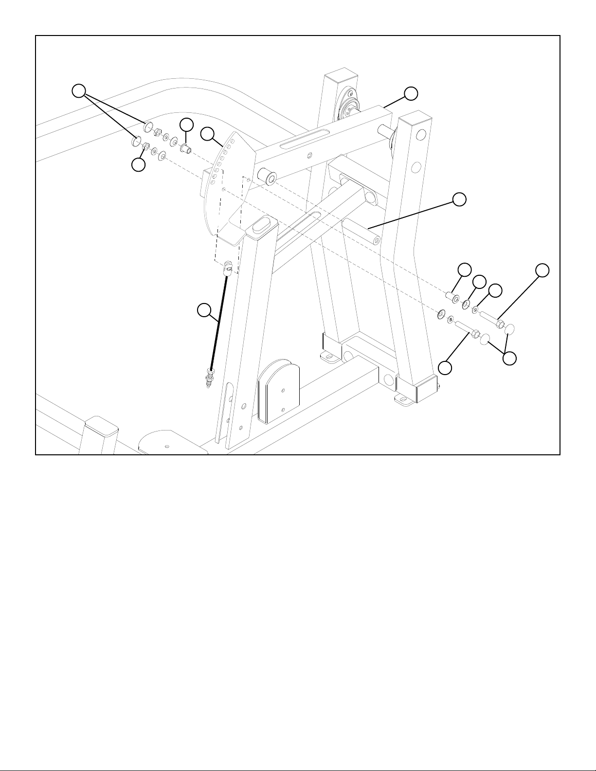
FIGURE 11
53
49
32
54
10
5
28
33
3/8 X 73mm 41
51
50
52BLACK
39 3/8 X 67mm
STEP 11:
• Finish assembling the PRESS ARM ADJUST PLATE (10) to the PIVOT ARM (5) using two RH CAPS (53), two BLACK RH CAPS
(52), one 3/8 X 67mm BOLT (39), one 3/8 X 73mm BOLT (41), four 3/8” SAE WASHERS (50), four 3/8” RH WASHERS (51), one 3/8 X
3/4” FLANGE SPACER (32), one 3/8 X 1” FLANGE SPACER (33), one MULTI PRESS CABLE (54) and two 3/8” LOW HEIGHT
LOCK NUTS (49) as shown in FIGURE 11. (NOTE: Assemble the MULTI PRESS CABLE to the second set of holes.) (NOTE: When
finished assembling, SECURELY tighten all three bolts.)
• Insert one 5-1/2” TAPPED PIVOT SHAFT (28) into the PIVOT ARM (5).
11
Page 12
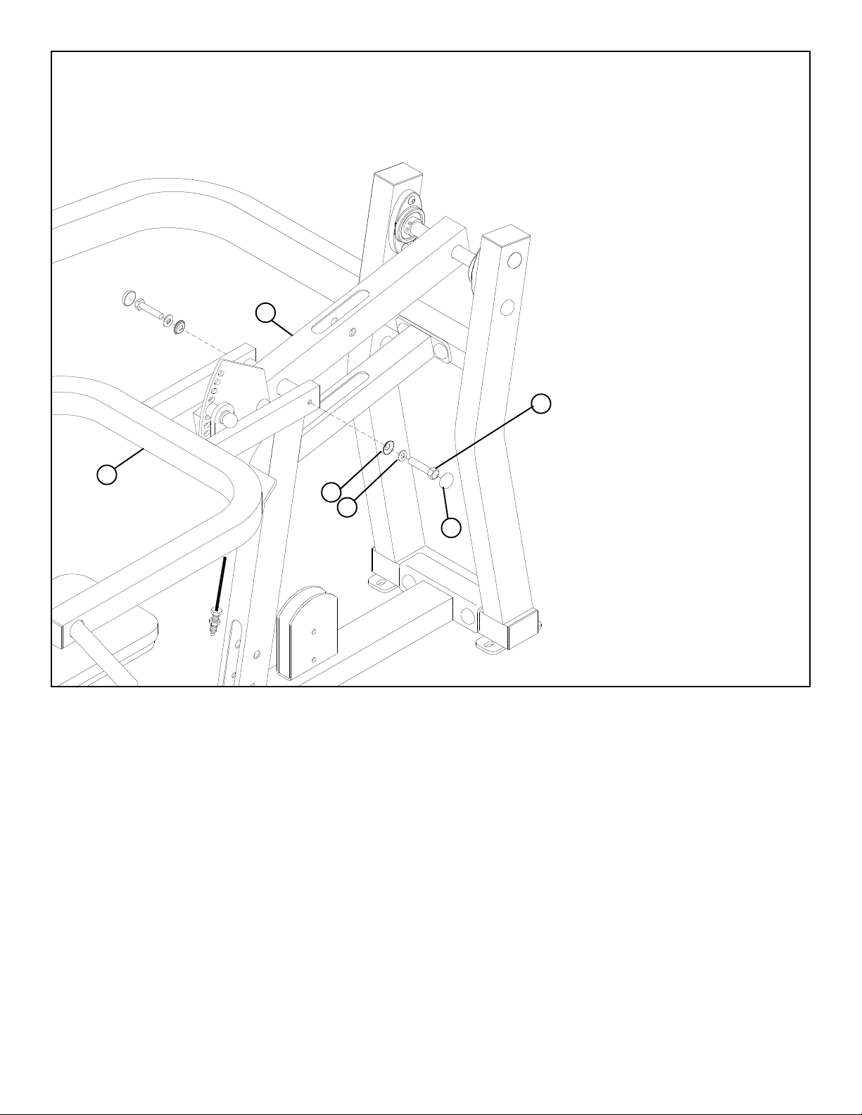
FIGURE 12
4
5
37 3/8 X 43mm
W/LOCTITE
51
50
53
STEP 12:
• SECURELY assemble the PRESS ARM (4) to the PIVOT ARM (5) using two RH CAPS (53), two 3/8 X 43mm BOLTS W/LOCTITE
(37), two 3/8” SAE WASHERS (50) and two 3/8” RH WASHERS (51) as shown in FIGURE 12.
12
Page 13
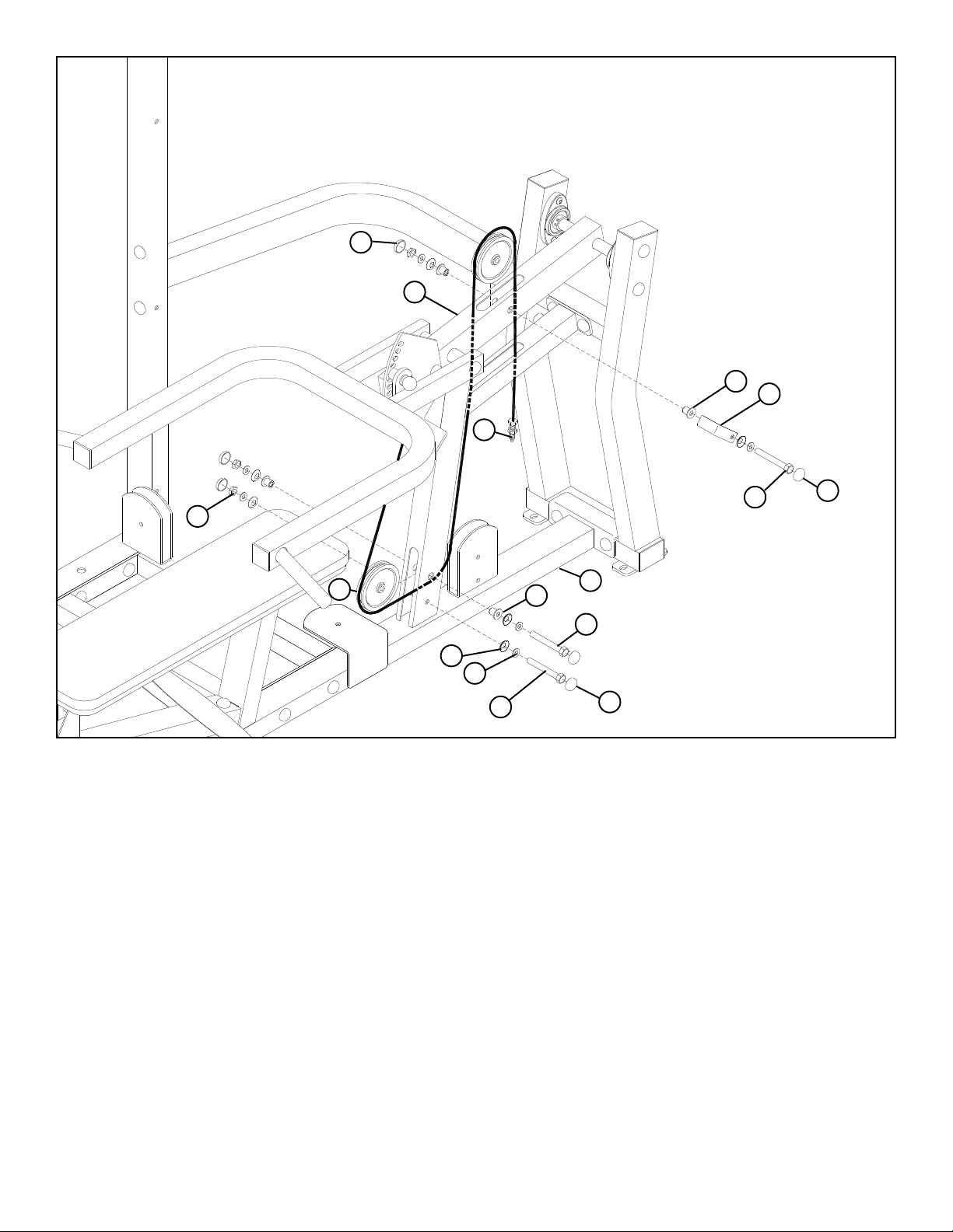
53
FIGURE 13
5
31
23
54
52 BLACK
49
19
51
50
3/8 X 61mm 38
3/8 X 70mm 40
8
31
39 3/8 X 67mm
53
STEP 13:
• Route the MULTI PRESS CABLE (54) through the PRESS FRAME (8) and SECURELY assemble one 4-1/2” PULLEY (19) to the
PRESS FRAME (8) using four RH CAPS (53), one 3/8 X 67mm BOLT (39), one 3/8 X 61mm BOLT (38), four 3/8” SAE WASHERS
(50), four 3/8” RH WASHERS (51), two 3/8 X 1/2” FLANGE SPACERS (31) and two 3/8” LOW HEIGHT LOCK NUTS (49) as shown
in FIGURE 13.
• Route the MULTI PRESS CABLE (54) through the PRESS FRAME (8) and PIVOT ARM (5) and SECURELY assemble one 4-1/2”
PULLEY (19) to the PIVOT ARM (5) using one BLACK RH CAP (52), one RH CAP (53), one 3/8 X 70mm BOLT (40), two 3/8” SAE
WASHERS (50), two 3/8” RH WASHERS (51), one 2-7/8” X 2-1/4” CABLE CLIP (23), two 3/8 X 1/2” FLANGE SPACERS (31) and one
3/8” LOW HEIGHT LOCK NUT (49) as shown in FIGURE 13.
13
Page 14
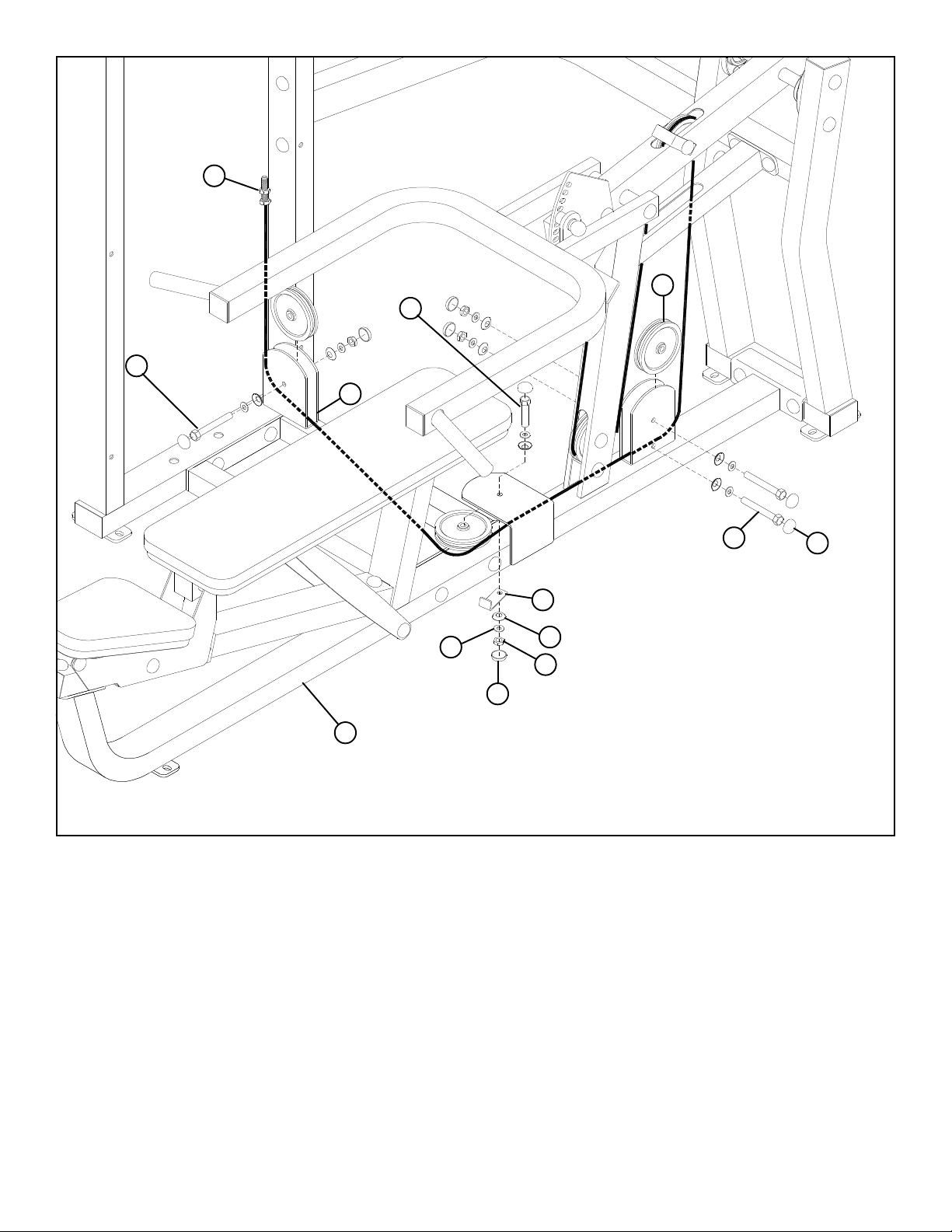
54
36 3/8 X 43mm
19
3/8 X 43mm 36
13
3/8 X 43mm 36
2
50
52 BLACK
8
51
49
53
FIGURE 14
STEP 14:
• Route the MULTI PRESS CABLE (54) through the vertical bracket on the PRESS FRAME (8) and SECURELY assemble one 4-1/2”
PULLEY (19) to the bracket using four RH CAPS (53), two 3/8 X 43mm BOLTS (36), four 3/8” SAE WASHERS (50), four 3/8” RH
WASHERS (51) and two 3/8” LOW HEIGHT LOCK NUTS (49) as shown in FIGURE 14.
• Route the MULTI PRESS CABLE (54) through the PRESS FRAME (8) and the horizontal bracket on the PRESS FRAME (8) and
SECURELY assemble one 4-1/2” PULLEY (19) to the bracket using one BLACK RH CAP (52), one RH CAP (53), one 3/8 X 43mm BOLT
(36), two 3/8” SAE WASHERS (50), two 3/8” RH WASHERS (51), one 3-1/2 X 1” CABLE CLIP (2) and one 3/8” LOW HEIGHT LOCK
NUT (49) as shown in FIGURE 14.
• Route the MULTI PRESS CABLE (54) through the vertical bracket on the BASE (13) and SECURELY assemble one 4-1/2” PULLEY
(19) to the bracket using two RH CAPS (53), one 3/8 X 43mm BOLT (36), two 3/8” SAE WASHERS (50), two 3/8” RH WASHERS
(51) and one 3/8” LOW HEIGHT LOCK NUT (49) as shown in FIGURE 14.
14
Page 15
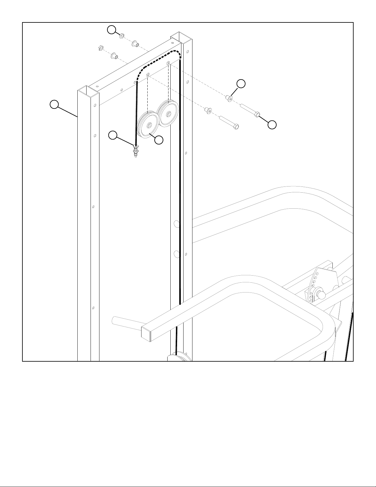
49
31
1
39 3/8 X 67mm
54
19
FIGURE 15
STEP 15:
• Route the MULTI PRESS CABLE (54) through the TOWER (1) and SECURELY assemble two 4-1/2” PULLEYS (19) to the TOWER
(1) using two 3/8 X 67mm BOLTS (39), four 3/8 X 1/2” FLANGE SPACERS (31) and two 3/8” LOW HEIGHT LOCK NUTS (49) as
shown in FIGURE 15.
15
Page 16
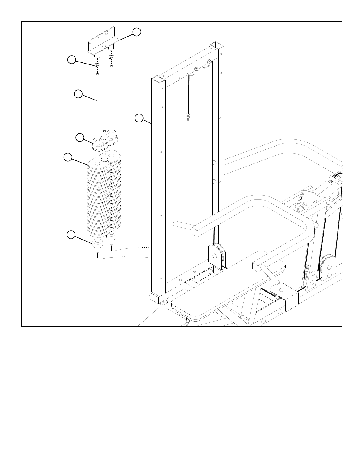
22
26
21
24
9
LUBRICATION NOTE:
When finished assembling the Weight
Stack, open the lube Pack provided
with this unit and apply a thin film of
Lubricant around the first 2 to 3
inches of each Guide Rod above the
Head Plate Assembly. After the
cables are installed, use of the machine will spread the lubricant over the
length of the Guide Rods and into the
1
Head Plate bushings
20
FIGURE 16
STEP 16:
• Insert two GUIDE RODS (21) into the TOWER (1) as shown on FIGURE 16.
• Slide two 3/4 X 2” WEIGHT STACK CUSHIONS (20) down over the GUIDE RODS (21) as shown in FIGURE 16.
• Using EXTREME CARE slide all twenty WEIGHT PLATES (22) down over the GUIDE RODS (21) on to the WEIGHT STACK CUSHIONS
(20). Make sure that the WEIGHT PLATES (22) are all facing as shown.
• Slide the HEAD PLATE ASSEMBLY (24) down over the GUIDE RODS (21) onto the weight stack as shown in FIGURE 16.
• Slide two 13/16” SHAFT COLLARS (26) and the GUIDE ROD SUPPORT (9) over the GUIDE RODS (21) as shown in FIGURE 16.
16
Page 17
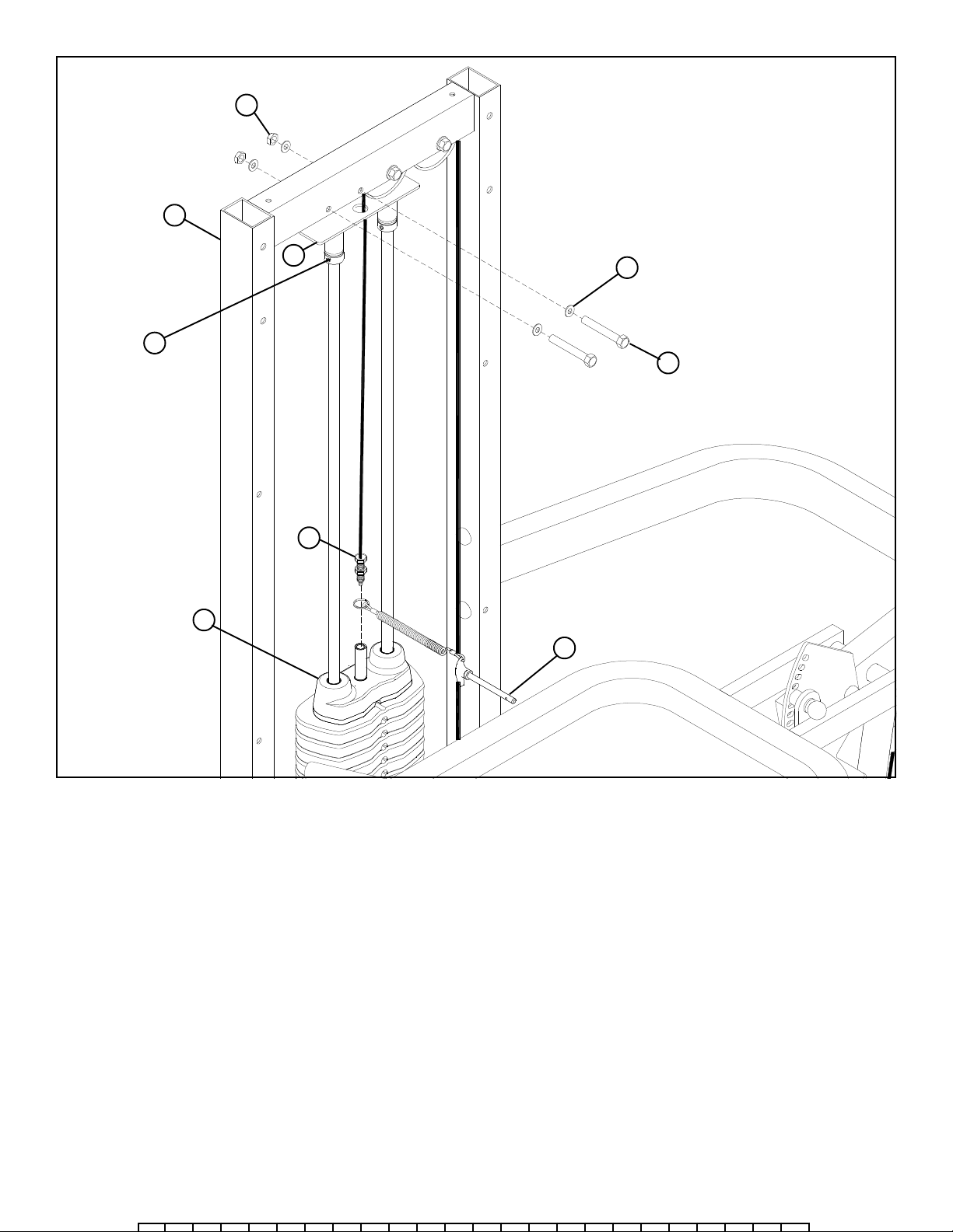
49
1
26
TIGHTEN!
24
9
54
25
60
39 3/8 X 67mm
FIGURE 17
STEP 17:
• Route the threaded end of the MULTI PRESS CABLE (54) through the GUIDE ROD SUPPORT (9) and SECURELY assemble the GUIDE
ROD SUPPORT (9) to the TOWER (1) using two 3/8 X 67mm BOLTS (39), four 3/8” FLAT WASHERS (60) and two 3/8” LOW HEIGHT
LOCK NUTS (49) as shown in FIGURE 17.
• Slide the 13/16” SHAFT COLLARS (26) up against the GUIDE ROD SUPPORT (9) and SECURELY tighten the set screws on the
SHAFT COLLARS (26). See FIGURE 17.
• Slide one WEIGHT STACK PIN (25) over the stem on the HEAD PLATE (24) as shown in FIGURE 12.
• LOOSELY thread the end of the MULTI PRESS CABLE (54) into the end of the stem on the HEAD PLATE (24). See FIGURE 17.
17
Page 18
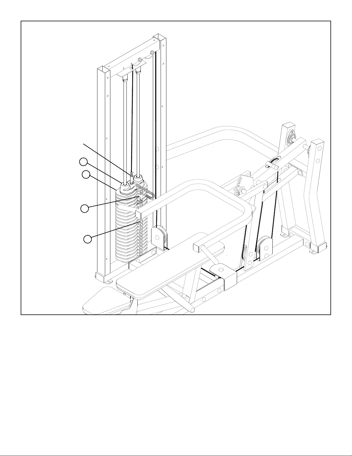
ADJUSTMENT
FIGURE 18
24
22
25
55
STEP 18:
• Adjustments can be made in the above locations to set the correct amount of tension in the cables.
• If upon completion of assembly, the HEAD PLATE (24) does not sit on top of the first WEIGHT PLATE (22), push the HEAD PLATE
(24) down, insert the WEIGHT STACK PIN (25) and perform several repetitions. This will relax the cable system and prevent the
HEAD PLATE (24) from lifting up. See FIGURE 18.
• If after completing the previous step, the HEAD PLATE (24) still does not sit on top of the first WEIGHT PLATE (22) or if
there is excess slack in the cable system, adjust the threaded ends of the CABLES attached to the HEAD PLATE (24) accordingly and
retighten the jam nuts. See FIGURE 18.
• For maximum performance, the HEAD PLATE (24) should just barely sit on the top WEIGHT PLATE (22).
• Apply WEIGHT STACK LABELS (55) to WEIGHT PLATES (22) and HEAD PLATE (24) as shown in FIGURE 18. Begin with number one
at the HEAD PLATE (24) with larger numbers in consecutive order towards bottom of weight stack.
18
Page 19
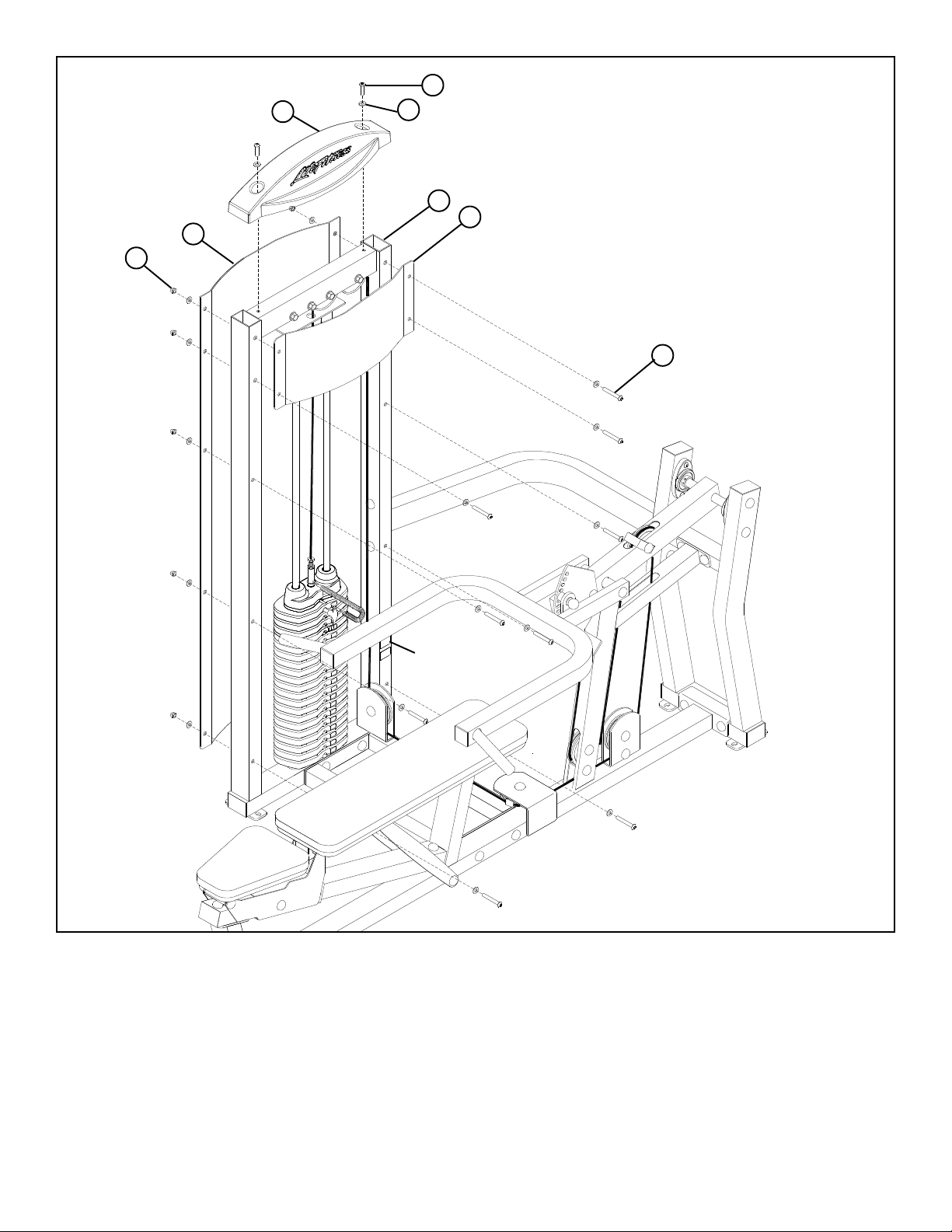
FIGURE 19
58
59
56
45 3/8 X 25mm BUTTON HEAD
48
1
57
47 3/8 X 90mm BUTTON HEAD
SERIAL # LOCATION
STEP 19:
• SECURELY assemble the FRONT SHROUD (57) and the REAR SHROUD (58) to the TOWER (1) using ten 3/8 X 90mm BUTTON HEAD
BOLTS (47), twenty 3/8” BLACK FLAT WASHERS (48) and ten 3/8” ACORN NUTS (59) as shown above.
• SECURELY assemble the TOWER CAP (56) to the TOWER (1) using two 3/8 X 25mm BUTTON HEAD BOLTS (45) and two 3/8”
BLACK FLAT WASHERS (48) as shown above.
Thank you for purchasing the LifeFitness FIT SERIES MULTI PRESS. If unsure of proper use of equip-
ment, call your local LifeFitness distributor or call the LifeFitness customer service department at
(800) 351-3737.
19
Page 20
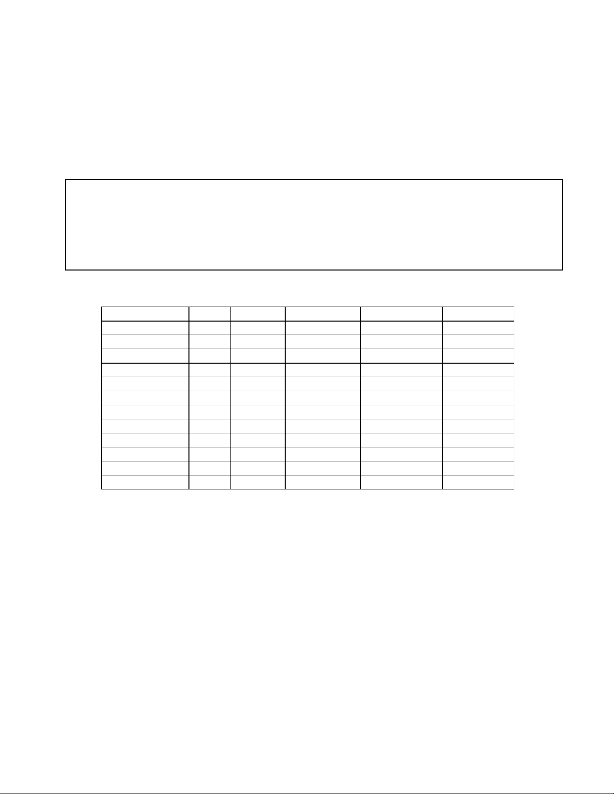
CAUTION-PLEASE READ
Action DAILY WEEKLY QUARTERLY BI-ANNUALLY AS NEEDED
CLEAN
Upholstery
X
Guide Rods
X
Hand Grips
X
INSPECT
Visual Overall
X
Cables
X
Hardware
X
Frame
X
Hand Grips
X
LUBRICATE
Guide Rods
X
There is a risk assumed by individuals who use this type of equipment. To minimize risk, please
follow these rules:
1. Inspect equipment daily. Tighten all loose connections and replace worn parts immediately.
Failure to do so may result in serious injury.
2. Do not allow minors or children to play on or around this equipment.
3. Exercise with care to avoid injury.
4. Consult your physician before beginning any exercise program.
WARRANTY INFORMATION
10 YEARS STRUCTURUAL FRAME
1 YEAR PILLOW BLOCKS, PULLEYS, WEIGHT PLATES AND GUIDE RODS
1 YEAR CABLES
90 DAYS UPHOLSTERY
PREVENTATIVE MAINTENANCE TIPS
Clean:
• Upholstery with mild soap and water.
• Guide rods with a cotton cloth.
• Hand grips with mild soap and water.
• Frame damage can be repaired with touch-up paint can be purchased from your LifeFitness customer service representative at (800)
351-3737
Inspect:
• Cables for wear or damage and proper tension (should not exceed 3/4” deflection.) Pay close attention at bends and attachment
points.
• Hardware should be checked for looseness. Tighten as required.
• Frames should be inspected for wear or damage.
• Hand Grips should be checked for wear or damage
Lubricate:
• Lube the Guide Rods. Apply the lubricant to a cotton cloth, then run the cotton cloth up and down the guide rods as needed. Do not
spray lubricant directly on the Guide Rods.
Thank you for purchasing the LifeFitness FIT SERIES MULTI PRESS. If unsure of proper use of equip-
ment, call your local LifeFitness distributor or call the LifeFitness customer service department at
(800) 351-3737.
20
 Loading...