

Life Fitness M051-00K96-0002 Assembly Instructions Manual
15” ATTACHABLE TV
ASSEMBLY INSTRUCTIONS
M051-00K96-0002 REV B

CORPORATE HEADQUARTERS
5100 River Road, Schiller Park, Illinois 60176 • U.S.A.
847.288.3300 • FAX: 847.288.3703
Service phone number: 800.351.3737 (toll-free within U.S.A., Canada)
Global Website: www.lifefi tness.com
INTERNATIONAL OFFICES
AMERICAS
North America
LIFE FITNESS, Inc.
5100 N River Road
Schiller Park, IL 60176 U.S.A
Telephone: (847) 288 3300
Fax: (847) 288 3703
Service Email: customersupport@lifefi tness.com
Service Website: www.lifefi tness.com/parts
Sales/Marketing Email:
commercialsales@lifefi tness.com
Operating Hours: 7:00 am-6:00 pm (CST)
Brazil
LIFE FITNESS Brasil
Av. Cidade Jardim, 900
Jd. Paulistano
São Paulo, SP 01454-000
BRAZIL
SAC: 0800 773 8282
Telephone: +55 (11) 3095 5200
Fax: +55 (11) 3095 5201
Service Email: suporte@lifefi tness.com.br
Sales/Marketing Email: lifefi tness@lifefi tness.com.br
Service Operating Hours:
9:00 - 17:00 (BRT) (Monday-Friday)
Store Operating Hours:
9:00 -20:00 (BRT) (Monday-Friday)
10:00 - 16:00 (BRT) (Saturday)
Latin America & Caribbean*
LIFE FITNESS Inc.
5100 N River Road
Schiller Park, IL 60176 U.S.A
Telephone: (847) 288 3300
Fax: (847) 288 3703
Service Email: customersupport@lifefi tness.com
Sales/Marketing Email:
commercialsales@lifefi tness.com
Operating Hours: 7:00am-6:00pm (CST)
______________________________________
EUROPE, MIDDLE EAST, & AFRICA (EMEA)
Netherlands & Luxemburg
LIFE FITNESS Atlantic BV
Bijdorpplein 25-31
2992 LB Barendrecht
THE NETHERLANDS
Telephone: (+31) 180 646 666
Fax: (+31) 180 646 699
Service Email: service.benelux@lifefi tness.com
Sales/Marketing Email:
marketing.benelux@lifefi tness.com
Operating Hours: 9.00h-17.00h (CET)
United Kingdom & Ireland
LIFE FITNESS UK LTD
Queen Adelaide
Ely, Cambs, CB7 4UB
Telephone: General Offi ce (+44)
1353.666017
Customer Support (+44) 1353.665507
Fax: (+44) 1353.666018
Service Email: uk.support@lifefi tness.com
Sales/Marketing Email: life@lifefi tness.com
Operating Hours:
General Offi ce: 9.00am - 5.00pm (GMT)
Customer Support: 8.30am - 5.00pm (GMT)
Germany & Switzerland
LIFE FITNESS Europe GMBH
Siemensstraße 3
85716 Unterschleißheim
GERMANY
Telephone: (+49) 89.31 77 51.0 (Germany)
(+41) 0848 000 901 (Switzerland)
Fax: (+49) 89.31 77 51.99 (Germany)
(+41) 043 818 07 20 (Switzerland)
Service Email: kundendienst@lifefi tness.com
Sales/Marketing Email:
kundenberatung@lifefi tness.com
Operating Hours: 08.30 -16.30h (CET)
Austria
LIFE FITNESS Austria
Vertriebs G.m.b.H.
Dückegasse 7-9/3/36
1220 Vienna
AUSTRIA
Telephone: (+43) 1.61.57.198
Fax: (+43) 1.61.57.198.20
Service Email: kundendienst@lifefi tness.com
Marketing/Sales Email:
kundenberatung@lifefi tness.com
Operating Hours: 08:30-16.30.h (MEZ)
Spain
LIFE FITNESS IBERIA
C/Frederic Mompou 5,1º1ª
08960 Sant Just Desvern Barcelona
AIN
SP
Telephone: (+34) 93.672.4660
Fax: (+34) 93.672.4670
Service Email: servicio.tecnico@lifefi tness.com
Sales/Marketing Email: info.iberia@lifefi tness.com
Operating Hours:
9.00h-18.00h (Monday-Thursday)
8.30h-15.00h (Friday)
Belgium
LIFE FITNESS Benelux NV
Parc Industrial de Petit-Rechain
4800 Verviers
BELGIUM
Telephone: (+32) 87 300 942
Fax: (+32) 87 300 943
Service Email: service.benelux@lifefi tness.com
Sales/Marketing Email:
marketing.benelux@lifefi tness.com
Operating Hours: 9.00h -17.00h (CET)
Italy
LIFE FITNESS Europe GmbH
Siemensstraße 3
85716 Unterschleißheim
GERMANY
Telephone: (+39) 02-55378611
Service: 800438836 (In Italy)
Fax: (+39) 02-55378699
Service Email: assistenzatecnica@lifefi tness.com
Sales/Marketing Email: info@lifefi tnessitalia.com
Operating Hours: 08:30 - 16:30h (CET)
Also check www.lifefitness.com for local representation or distributor/dealer.
All Other EMEA Countries &
Distributor Business C-EMEA*
Bijdorpplein 25-31
2992 LB Barendrecht
THE NETHERLANDS
Telephone: (+31) 180 646 644
Fax: (+31) 180 646 699
Service Email: service.db.cemea@lifefi tness.com
Sales/Marketing Email:
marketing.db.cemea@lifefi tness.com
Operating Hours: 9.00h-17.00h (CET)
____________________________________
ASIA PACIFIC (AP)
Japan
LIFE FITNESS Japan
Japan Nippon Brunswick Bldg., #8F
5-27-7 Sendagaya
Shibuya-Ku, Tokyo
Japan 151-0051
Telephone: (+81) 3.3359.4309
Fax: (+81) 3.3359.4307
Service Email: service@lifefi tnessjapan.com
Sales/Marketing Email:sales@lifefi tnessjapan.com
Operating Hours: 9.00h-17.00h (JAPAN)
China and Hong Kong
LIFE FITNESS Asia Pacifi c LTD
Room 2610, Miramar Tower
132 Nathan Road
Tsimshatsui, Kowloon
HONG KONG
Telephone: (+852) 2891.6677
Fax: (+852) 2575.6001
Service Email: HongKongEnquiry@lifefi tness.com
Sales/Marketing Email:
ChinaEnquiry@lifefi tness.com
Operating Hours: 9.00h-18.00h
All Other Asia Pacifi c countries &
distributor business Asia Pacifi c*
Room 2610, Miramar Tower
132 Nathan Road
Tsimshatsui, Kowloon
HONG KONG
Telephone: (+852) 2891.6677
Fax: (+852) 2575.6001
Service Email: HongKongEnquiry@lifefi tness.com
Sales/Marketing Email:
ChinaEnquiry@lifefi tness.com
Operating Hours: 9.00h-18.00h
1

TABLE OF CONTENTS
1. Important Safety Instructions 4
2. Media Connections 9
3. Installation 11
Treadmills 11
Models: 95T Elevation Inspire & 95T Elevation Discover SI 11
Models: CLST & 97T Integrity Series 15
Models: 91Ti & 90T 17
Models: 97Ti, 95Ti & 93T 19
Cross-Trainers 21
Models: 95X Elevation Inspire & 95X Elevation Discover SI 21
Model: CLSX Integrity Series 25
Models: 95Xi, 93X & 90X 27
Upright Lifecycle® Exercise Bikes 29
Models: 95C/97C Elevation Inspire & 95C/97C Elevation Discover SI 29
Model: CLSC Integrity Series 33
Models: 95Ci, 93C & 90C 35
Recumbent Lifecycle® Exercise Bikes 37
Models: 95R Elevation Inspire & 95R Elevation Discover SI 37
Model: CLSR Integrity Series 41
Models: 95Ri, 93R & 90R 43
Summit Trainers 45
Model: CLSL Integrity Series 45
Model: 95Li 46
Stairclimbers 48
Model: CLSS Integrity Series 48
Models: 95Si, 93S & 90S 50
© 2013 Life Fitness, a division of Brunswick Corporation. All rights reserved.
2

Note: This equipment has been tested and found to comply with the limits for a Class B digital device pursuant to Part 15
of the FCC Rules. These limits are designed to provide reasonable protection against harmful interference in a residential installation. This equipment generates, uses, and can radiate radio frequency energy and, if not installed and used
in accordance with the instructions, may cause harmful interference with radio communications. However, there is no
guarantee that interference will not occur in a particular installation. If this equipment does cause harmful interference to
radio or television reception, which can be determined by turning the equipment off and on, the user is encouraged to try
to correct the interference by one or more of the following measures:
Reorient or relocate the receiving antennas.
Increase the separation between the equipment and receiver.
Connect the equipment into an outlet on a circuit different from that to which the receiver is connected.
Consult the dealer or an experienced radio/TV technician for help.
CAUTION: Any changes or modifi cations to this equipment could void the product warranty.
Mise en garde : tout changement ou toute modifi cation de ce matériel peut annuler la garantie
du produit.
Any service, other than cleaning or user maintenance, must be performed by an authorized service representative.
3

IMPORTANT SAFETY INSTRUCTIONS
Read all instructions before using LIFE FITNESS products.
DANGER: To reduce the risk of electrical shock, always unplug this Life Fitness product before cleaning or at-
tempting any maintenance activity.
WARNING: To reduce the risk of burns, fi re, electric shock, or injury, it is imperative to connect each product to
a properly grounded electrical outlet.
WARNING: To prevent injury, this product must be securely attached in accordance with the installation instruc-
tions.
Never operate a Life Fitness product if it has a damaged power cord or electrical plug, or if it has been dropped,
damaged, or even partially immersed in water. If this occurs, contact Life Fitness Customer Support Services as
outlined on page one of this manual.
Position this product so that the AC power cord plug is accessible to the user.
Keep the power cord away from heated surfaces. Do not pull the equipment by the power cord or use the cord as
a handle.
If the electrical supply cord is damaged, it must be replaced by the manufacturer, an authorized service agent, or
a similarly qualifi ed person to avoid a hazard.
Always follow the product instructions for proper operation.
Never insert objects into any opening of the Life Fitness product. If an object should drop inside, unplug this Life
Fitness product and carefully retrieve it while the unit is not in use. If the object cannot be reached, contact Life
Fitness Customer Support Services.
Do not use this product outdoors, near swimming pools or in areas of high humidity. Do not expose this product
to dripping or splashing liquids. If the product should be exposed to liquid, contact Life Fitness Customer Support
Services.
Never operate a Life Fitness product with the air openings blocked. Keep air openings free of lint, hair, or any ob-
structing material.
Use this product only for its intended use as described in this manual. Do not use attachments that have not been
recommended by the manufacturer.
SAVE THESE INSTRUCTIONS FOR FUTURE REFERENCE.
4

CONSIGNES DE SÉCURITÉ IMPORTANTES
Lire toutes les instructions avant d’utiliser les appareils LIFE FITNESS.
DANGER: Pour réduire les risques de décharge électrique, toujours débrancher cet appareil Life Fitness avant
le nettoyage ou toute mesure d’entretien.
AVERTISSEMENT: Pour réduire les risques de brûlures, d’incendies, de décharges électriques ou de bles-
sures, chaque appareil doit absolument être branché sur une prise électrique correctement mise à la terre.
AVERTISSEMENT: Pour prévenir les blessures, ce produit doit être solidement fi xé, conformément aux in-
structions d’installation.
Ne jamais faire fonctionner un produit Life Fitness dont la fi che ou le cordon d’alimentation est endommagé, ni
aucun appareil qui serait tombé ou aurait été endommagé ou même partiellement plongé dans l’eau. Si cela se
produit, communiquer avec le service à la clientèle de Life Fitness comme indiqué sur une page de ce manuel
Placer l’appareil de façon à ce que l’utilisateur ait accès à la fi che du cordon d’alimentation.
Tenir le cordon d’alimentation à l’écart de toute surface chauffée. Ne pas tirer l’appareil par le cordon
d’alimentation; ne pas utiliser le cordon comme poignée.
Si le cordon d’alimentation électrique est endommagé, il doit être remplacé par le fabricant, par un réparateur
agréé ou par une personne qualifi ée afi n d’éviter tout danger.
Toujours suivre les instructions sur le produit pour s’assurer de son fonctionnement adéquat.
Ne jamais insérer aucun objet dans les ouvertures du produit Life Fitness. Si un objet tombe à l’intérieur du
produit Life Fitness, le débrancher et extraire l’objet soigneusement pendant que l’appareil est débranché. S’il est
impossible d’atteindre l’objet, communiquer avec le service à la clientèle de Life Fitness.
Ne pas utiliser ce produit à l’extérieur, près d’une piscine ou dans des endroits très humides. Ne pas exposer ce
produit à des liquides qui s’égouttent ni à des éclaboussures. Si le produit est en contact avec des liquides, com-
muniquer avec le service à la clientèle de Life Fitness.
Ne jamais faire fonctionner d’appareil Life Fitness dont les orifi ces d’aération seraient bloqués. Les garder ex-
empts de peluches, de cheveux ou de toute obstruction.
Utiliser ce produit uniquement pour les fi ns auxquelles il est destiné et de la manière décrite dans le présent man-
uel. Ne pas utiliser d’accessoires qui ne sont pas recommandés par le fabricant.
CONSERVER CES INSTRUCTIONS POUR TOUT USAGE ULTÉRIEUR.
5
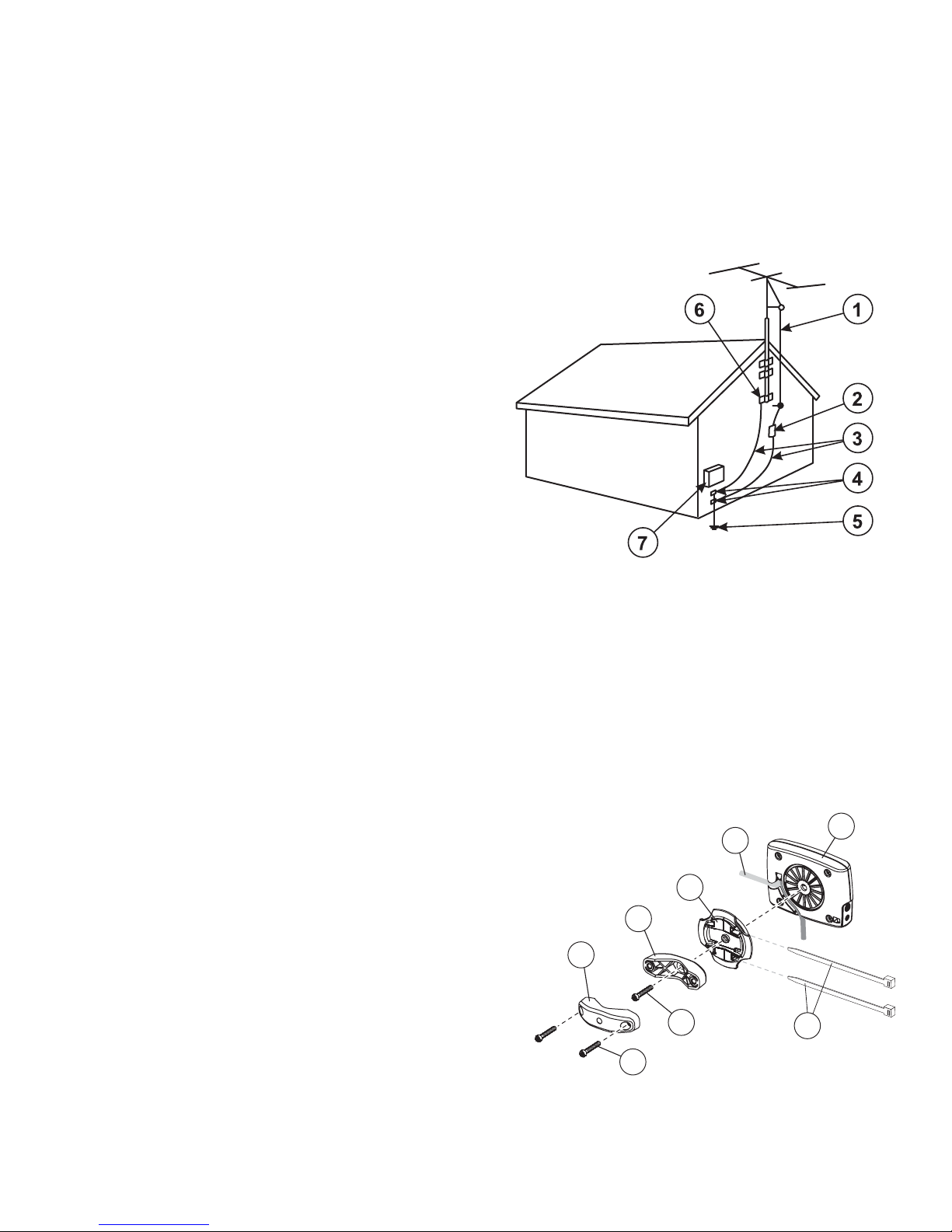
NOTE TO THE CATV INSTALLER
This reminder is provided to call the CATV system installer’s attention to Article 820-40 of the NEC that provides guidelines for proper grounding and, in particular, specifi es that the cable ground shall be connected to the grounding system of
the building as close to the point of cable entry as practical.
Antenna Grounding According to the NEC
Antenna Grounding According to the National Electrical Code, ANSI/NFPA 70.
1. Antenna lead in wire
2.
Antenna discharge unit (NEC Section 810-20)
3. Grounding conductors (NEC Section 810-21)
4. Ground clamp
5. Power service grounding electrode system (NEC Article
250, Part H)
6. Ground clamp
7. Electric service equipment
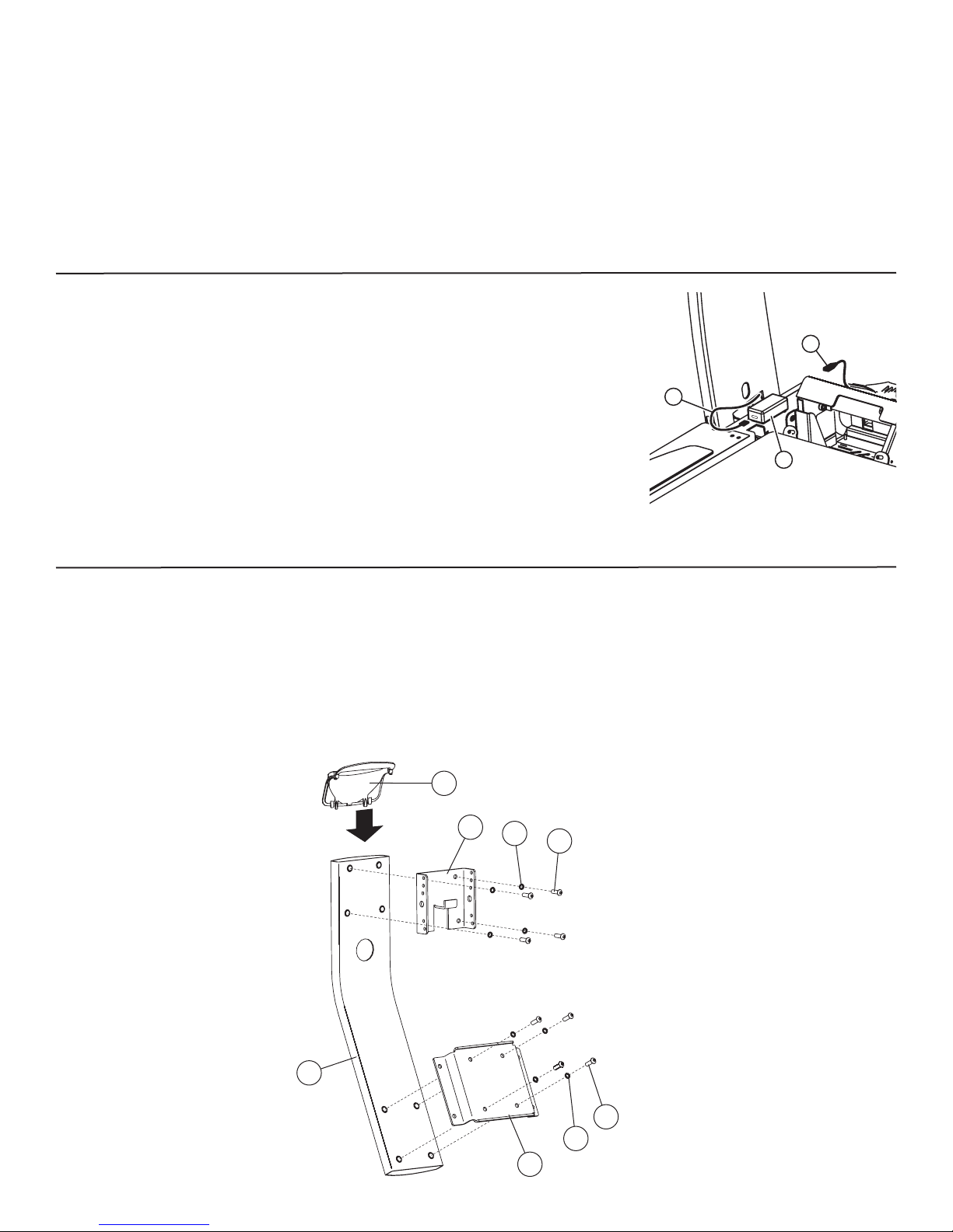
REMOTE CONTROL CONFIGURATION
Tools Required: Metric Allen Set
Mount the PIVOT DISC (A) and FRONT BRACKET (B) to the back of the REMOTE CONTROL (C) using one SCREW
(D). Leave the screw loose at this time.
Select a user accessible location to mount the remote control. Position the remote with bracket at the desired location.
Pivot the remote as necessary for optimal user access.
Note: If the desired location is such that the bracket will not work for mounting, remove the front bracket and reinstall the
pivot disc. The remote can now be installed using the two CABLE TIES (E) or fastener discs provided with the remote. Be
sure the pivot disc is oriented to accommodate the mounting surface.
Tighten the screw to secure the pivot disc and front bracket to the
remote.
Reposition the remote with bracket in the desired location and secure
the remote to the equipment using the REAR BRACKEt (F) and two
SCREWS (G). Tighten the screws securely.
Note: Two differing length of SCREWS (G) are included to
accommodate various mounting thicknesses.
Note: The REMOTE CABLE (H) can be routed through any of two
cable routing channels in the back of the remote or around the pivot
disc.
H
A
B
F
D
G
C
E
6

MEDIA CONNECTIONS: NTSC / ATSC / QAM WITH PRO:IDIOM
12VDC
MTI
Hi-Def
CVBS
CATV
Power In MTI
Network In
USB Hi-Def Input S-Video
Video In
Audio In
RF Coaxial
Wired Remote /
Media Cable
Description Connector Type
Power In 12 Volt DC Power In Power Jack
MTI Lodgenet Box Connection RJ45
Network In Internet Connection RJ45
USB USB Flash Drive USB Type A
High-Defi nition Input High-Defi nition Audio & Video Connection High-Defi nition
Audio Out
S-Video S-Video Signal In S-Video
Video In Video In RCA (yellow)
Audio In Stereo Line In RCA (red and white)
RF Coaxial Antenna / Cable Connection RF F-Type
Wired Remote /
Wired Remote Control Connection Remote Control
Media Cable
Audio Out Headphone Connection 3.5mm stereo jack, 0.3W
7
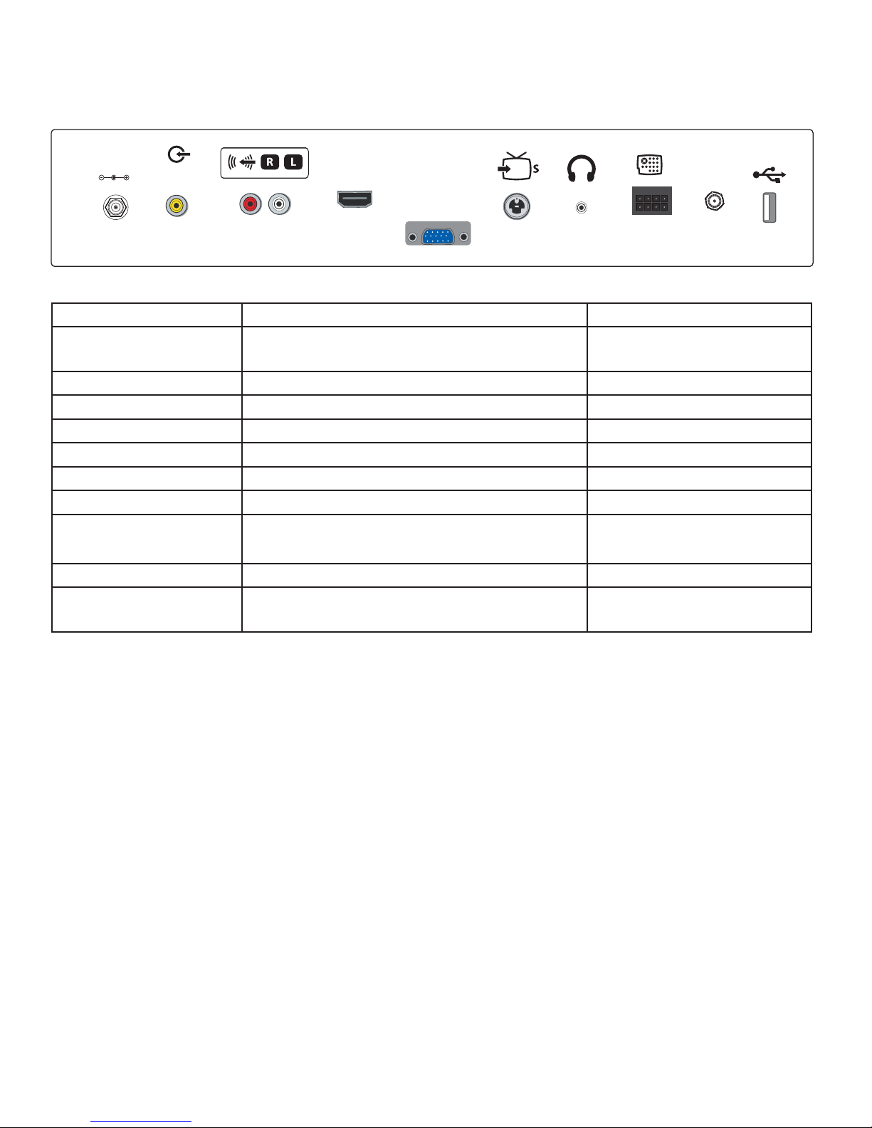
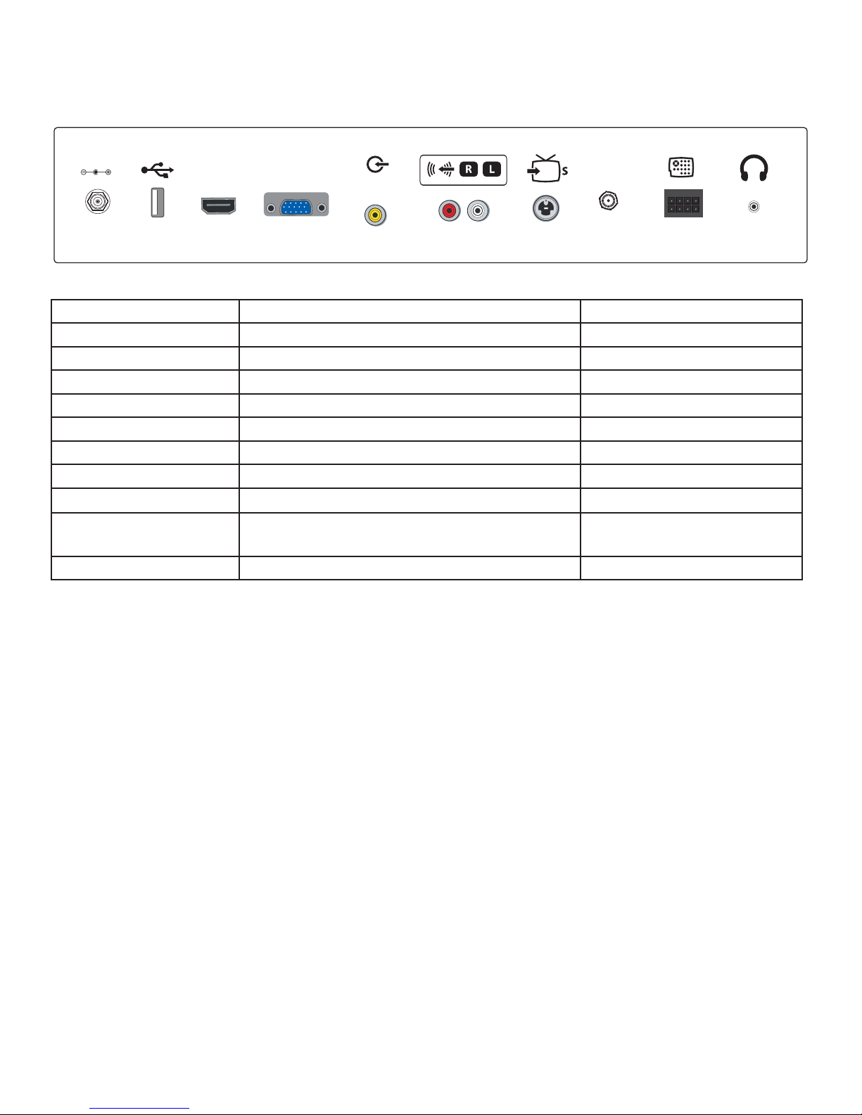
MEDIA CONNECTIONS: NTSC / ATSC / QAM
12VDC
Power In
CVBS
Video In
Audio In
Right
Left
Hi-Def
High
Definition
Input
VGA In
S-Video In
Audio Out
Wired Remote/
Media Cable
CATV
RF
Coaxial
USB
Description Connector Type
Power In 12 Volt DC Power In Power Jack
Video In Video In RCA (yellow)
Audio In Stereo Line In RCA (red and white)
High-Defi nition Input High-Defi nition Audio & Video Connection High-Defi nition
VGA In PC-Video Connection VGA
S-Video In S-Video Signal In S-Video
Audio Out Headphone Connection 3.5mm stereo jack, 0.3W
Wired Remote /
Wired Remote Control Connection Remote Control
Media Cable
RF Coaxial Antenna / Cable Connection RF F-Type
USB USB Flash Drive USB Type A
8
MEDIA CONNECTIONS: NTSC / ISDB-T
Hi-Def
D-SUB
CVBS
CATV
12VDC
USB
High
Definition
Input
Audio In
Right
Left
Video In
S-Video In
RF
Coaxial
Audio Out
Wired Remote/
Media Cable
Power In
Description Connector Type
USB USB Flash Drive USB Type A
High Defi nition Input High-Defi nition Audio & Video Connection High-Defi nition
D-SUB PC-VIdeo Connection VGA
Audio In Stereo Line In RCA (red and white)
Video In Video In RCA (yellow)
S-Video In S-Video Signal In S-Video
RF Coaxial Antenna / Cable Connection RF F-Type
Audio Out Headphone Connection 3.5mm stereo jack, 0.3W
Wired Remote /
Wired Remote Control Connection Remote Control
Media Cable
Power In 12 Volt DC Power In Power Jack
9
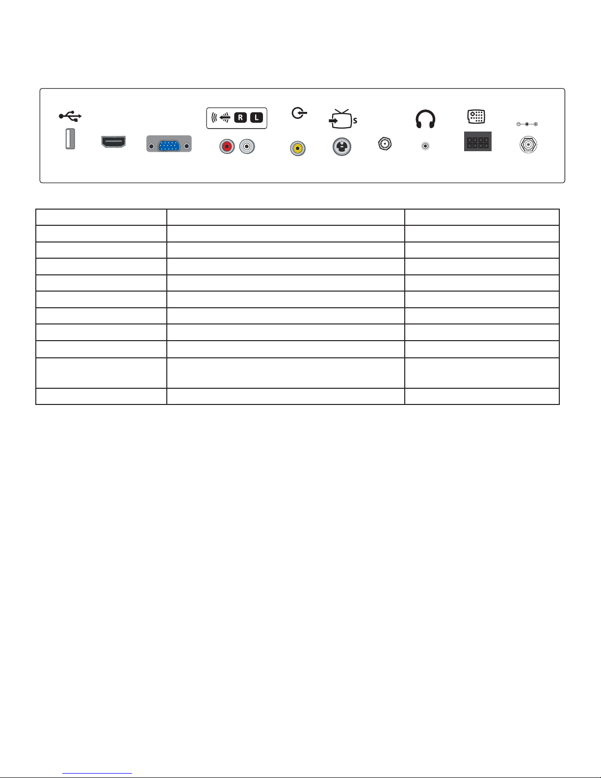
MEDIA CONNECTIONS: PAL / SECAM / DVB-T2
12VDC
Hi-Def
VGA In
CVBS
CATV
Power In
USB
High
Definition
Input
Video In
Audio In
Right
Left
S-Video In
RF
Coaxial
Wired Remote/
Media Cable
Audio Out
Description Connector Type
Power In 12 Volt DC Power In Power Jack
USB USB Flash Drive USB Type A
High-Defi nition Input High-Defi nition Audio & Video Connection High-Defi nition
VGA In PC-Video Connection VGA
Video In Video In RCA (yellow)
Audio In Stereo Line In RCA (red and white)
S-Video In S-Video Signal In S-Video
RF Coaxial Antenna / Cable Connection RF F-Type
Wired Remote /
Wired Remote Control Connection Remote Control
Media Cable
Audio Out Headphone Connection 3.5mm stereo jack, 0.3W
10
INSTALLATION
Models: 95T Elevation Inspire & 95T Elevation Discover SI
Tools Required: Phillips Screwdriver, Metric Allen Set, M16 & M17 Wrench
Parts Not Used From Kit: (1) Main Bracket Cap, (1) Grommet
1. Turn off the treadmill and unplug it from the power outlet.
For 95T Elevation Inspire Units Only:
1a. Remove the six screws securing the motor cover. Remove the motor
cover and set it and the screws aside.
1b. Remove the protective liner from one of the provided fastener strips.
Attach the fastener strip to the bottom of the POWER BLOCK (1).
Interlock the remaining fastener strip to the installed fastener strip.
Remove the remaining protective liner from fastener strip and secure
the power block to the frame as shown.
2
2
1c. Plug the POWER CORDS (2) leading from the motor compartment
and left upright into their respective ends of the POWER BLOCK (1).
Feed excess cable into the left upright.
1d. Re-install the motor cover using the six previously removed screws.
2. Attach the LOWER MOUNTING BRACKET (3) to the MAIN BRACKET (4) as shown using four SCREWS (5) and
WASHERS (6) each. Tighten the screws securely (8-10 ft. lbs.).
3. Slide the NEW BRACKET COVER (7) over the top end of the MAIN BRACKET (4) and down to meet the LOWER
MOUNTING BRACKET (3) as shown.
4. Attach the TV BRACKET (with bent tab) (8) to the MAIN BRACKET (4) as shown using four SCREWS (5) and
WASHERS (6). Tighten the screws securely (8-10 ft. lbs.).
1
7
8
6
5
4
5
6
3
11
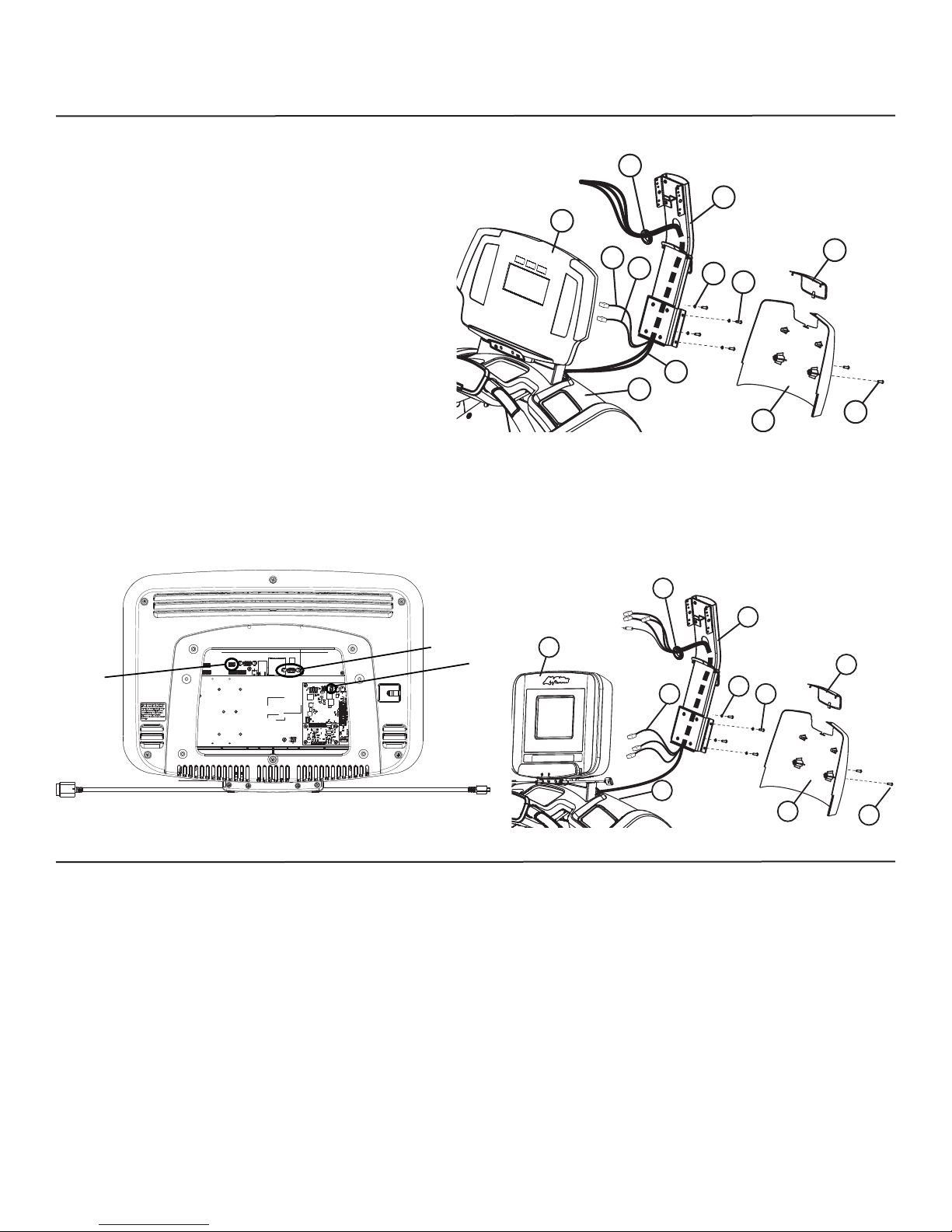
5. Remove the two SCREWS (9) securing the REAR CONSOLE COVER (10) to the frame. Remove the rear console
cover. Re move the TOP INSERT (11) from the rear console cover and discard. Set the rear console cover aside.
6. Console Cable Connections
For 95T Elevation Inspire Units Only:
6a. Carefully pull the MEDIA CABLE BUNDLE
(12) (Power and Coaxial) from inside the
CONSOLE BRIDGE (13). Un bundle and
straighten the media cables.
6b. Install the coaxial extension coupler and
C
14
4
A
B
6
5
coaxial extension cable.
6c. Connect the I-R REMOTE CONTROL (A)
and VIDEO (B) CABLES to the back of the
DISPLAY CONSOLE (C).
6d. Tape the ends of all CABLES (Power,
12
13
10
Coaxial, I-R Remote Control, Video) together.
For 95T Elevation Discover SI Units Only:
Note: Only the COAXIAL CABLE is inside the CONSOLE BRIDGE.
6a. Attach the three MEDIA CABLES (12) to the back of the Discover SI CONSOLE (C) as shown below.
14
11
9
4
High-Def
Power
Remote
Treadmill Elevation Discover SI Console
C
11
6
12
13
5
10
9
7. Hold the MAIN BRACKET ASSEMBLY (4) close to the CONSOLE BRIDGE (13) as shown. With the holes facing
upward, feed the taped end of the MEDIA CABLES (12) through the bottom of the main bracket assembly and out of
the upper hole as shown. Carefully pull excess media cable through the main bracket assembly.
8. Slide one GROMMET (14) over the taped end of the MEDIA CABLES (12). Install the grommet into the top access
hole.
9. Tilt the MAIN BRACKET ASSEMBLY (4) upward and align the LOWER MOUNTING BRACKET (3) holes with those
in the console bracket posts. Secure the MAIN BRACKET ASSEMBLY using four SCREWS (5) and WASHERS
(6). Tighten the screws securely (8-10 ft. lbs.).
CAUTION: Raise the BRACKET COVER (7) to meet the exiting MEDIA CABLES before mounting the MAIN BRACKET
ASSEMBLY.
12
For Achieve Console Units Only:
a. Remove the two SCREWS (A) and WASHERS (B)
securing the BOTTOM INSERT (C). Remove the
BOTTOM INSERT. Do not discard the SCREWS and
WASHERS.
H
b. Locate the REMOTE CONTROL (D) and REMOTE
BRACKET (E). Feed the REMOTE CABLE (F)
through the large access hole in the REMOTE BRACKET
(E). With the REMOTE CONTROL (D) and REMOTE
BRACKET (E) oriented as shown, secure them together
using one SCREW. (G) Tighten the screw securely.
c. Carefully feed the REMOTE CABLE (F) through the open ing in the bottom of the CONSOLE (H) and through
the back of the console. Position the REMOTE BRACKET
(E) into position replacing the BOTTOM INSERT (C).
Secure the REMOTE BRACKET (E) using the previously
removed SCREWS (A) and WASHERS (B).
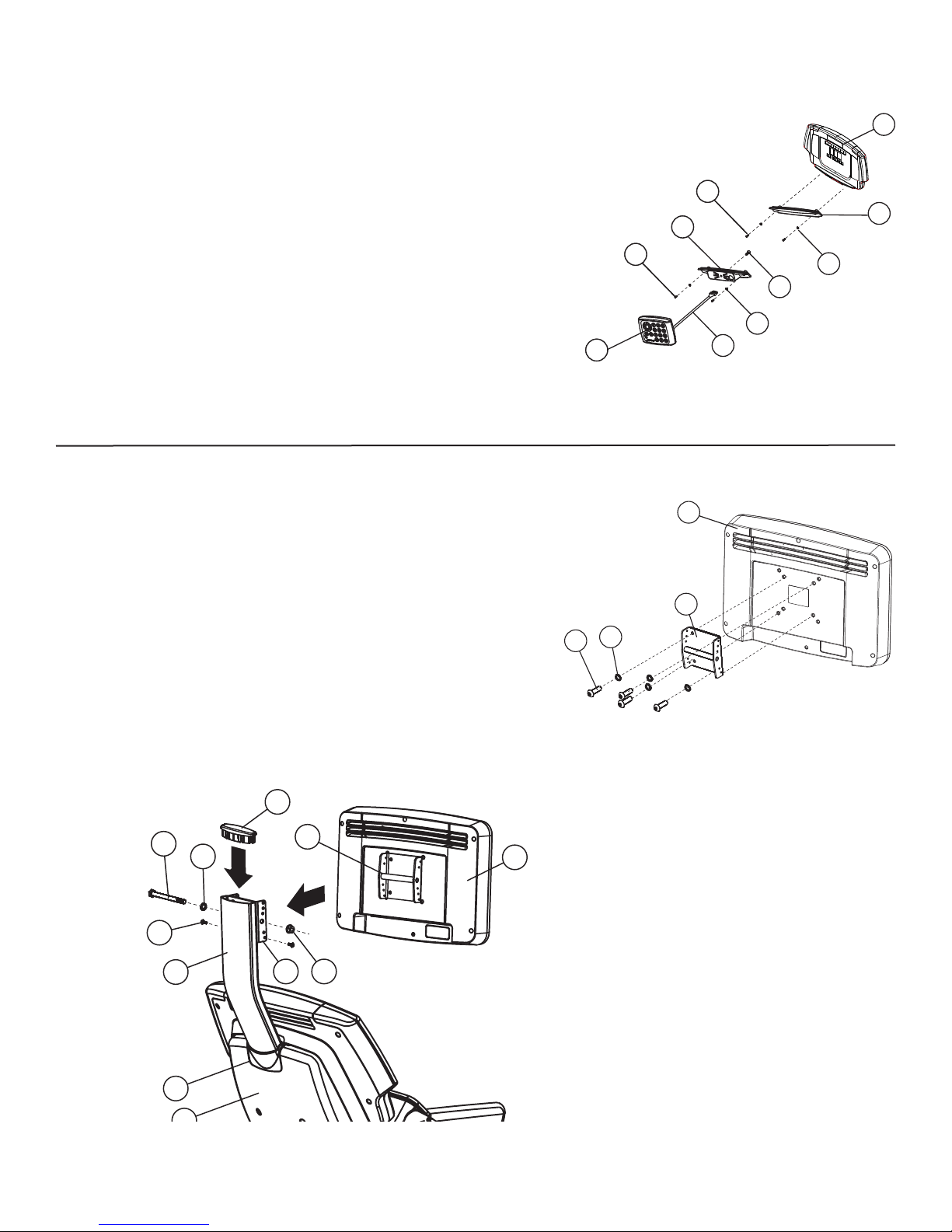
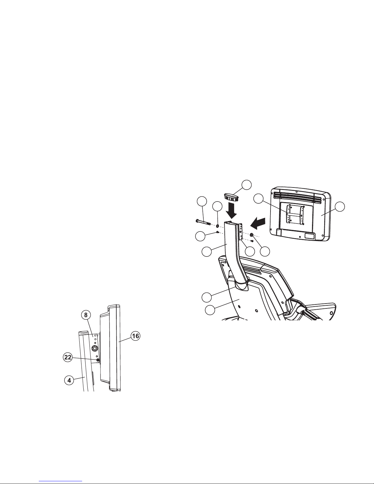
10. With the remaining TV BRACKET (15) oriented as shown, install
it to the back of the ATTACHABLE TV (16) using four SCREWS (17)
and WASHERS (18). Tighten the screws securely (8-10 ft. lbs.).
Note: Be sure the side holes of the TV bracket are oriented as shown.
11. Position the TV BRACKETS (8 & 15) together as shown and secure
them together using one BOLT (18), WASHER (19) and NUT (20).
Leave the bolt and nut loose at this time.
Note: Be sure the PIVOT POST of the TV BRACKET engages onto TV
BRACKET (8).
17
16D
18
AA
16E
AA
G
B
F
16
15
B
C
21
18
19
15
22
4
8
20
7
16
13
12. Connect all cables to their corresponding jacks located on the bottom of the TV (16). Re move the tape from the end
of the MEDIA CABLES (Power, Coaxial, I-R Remote Control, Video).
See the Media Connections pages in this manual for detailed information. Feed any excess media cable into the
MAIN BRACKET (4).
13. Install the TOP MAIN BRACKET CAP (21) to the top of the MAIN BRACKET ASSEMBLY (4).
14. Replace the REAR CONSOLE COVER (10) and secure it using the previously removed two SCREWS (9).
Tighten the screws securely (8-10 ft. lbs.). Do not overtighten the screws.
15. Slide the BRACKET COVER (7) down to meet the REAR CONSOLE COVER (10). Snap the BRACKET COVER
into the REAR CONSOLE COVER.
16. Align the lowest side holes on the TV BRACKETS (8 &15). Secure the TV BRACKET into proper position
using one SCREW (22) on each side.
17. Plug in the treadmill and power on the treadmill and TV. Refer to the ATTACHABLE Operation Manual for
proper TV setup.
21
18
22
4
7
10
19
15
16
8
20
14

Models: CLST & 97T (Integrity Series)
Tools Required: Standard Screwdriver, Phillips Screwdriver, Metric Hex Key Set, Side Cutters
Note: Proceed with the following steps immediately after attaching the DISPLAY CONSOLE as described in the
Integrity Series Assembly Instructions. Do not install the ACCESSORY TRAYS.
1. Insert one end of the AUDIO / VIDEO / I-R CABLE ASSEMBLY (a) into the console connector. Route the other end
through the HOLE (a1) on the right upright and through the GROMMET (a2). Continue routing the cable assembly
through the hole of the TV MOUNTING BRACKET END CAP (a3), through the TV MOUNTING BRACKET TUBE
(g), and exiting through the CENTER HOLE (a4) of the TV MOUNTING BRACKET TUBE (g).
2. Route the POWER SUPPLY CORD (b) and COAXIAL CABLE (c) through the left upright, out the HOLE (b1) on the
left upright and through the GROMMET (b2). Route the cable through the hole of the TV MOUNTING
BRACKET END CAP (b3), through the TV MOUNTING BRACKET TUBE (g), and exiting through the CENTER HOLE
(a4) of the TV MOUNTING BRACKET TUBE (g). Install a GROMMET (a5) onto the CENTER HOLE (a4).
g
a1
a2
To console
connector
a4
a5
b3
b
c
a3
a
b1
b2
3. If through-holes in the four CONSOLE BOSSES (d) are not present, use a 5/16” drill from the top center of the four
console bosses to create through-holes. Note: Be careful not to damage the threads of the brass inserts when
drilling the through-holes in the console bosses (d).
CAUTION: Wear eye safety equipment when drilling the through-holes in the console bosses.
4. Locate the four RETAINING SPACERS (e). Position the RETAINING SPACERS over the CONSOLE BOSSES (d) as
shown. Be sure the RETAINING spacers are fully nested over the structural ribs inside the REAR CONSOLE (f).
5. Position the BRACKET TUBE (g) with the TV MOUNTING BRACKET PLATE (j) facing upward. Position two
SCREWS (h) on either side through the CONSOLE BOSSES (d). Install four NYLOCK NUTS (i) onto the installed
SCREWS (h) securing the RETAINING SPACERS (e) and BRACKET TUBE (g) to the REAR CONSOLE. Tighten the
NYLOCK NUTS securely. Do not overtighten the NYLOCK NUTS.
j
g
h
i
e
f
d
To console
connector
15
 Loading...